EP1584356B1 - Parametermessandordnung für Übungsgerät - Google Patents
Parametermessandordnung für Übungsgerät Download PDFInfo
- Publication number
- EP1584356B1 EP1584356B1 EP04027499A EP04027499A EP1584356B1 EP 1584356 B1 EP1584356 B1 EP 1584356B1 EP 04027499 A EP04027499 A EP 04027499A EP 04027499 A EP04027499 A EP 04027499A EP 1584356 B1 EP1584356 B1 EP 1584356B1
- Authority
- EP
- European Patent Office
- Prior art keywords
- treadmill
- deck
- sensor
- aerial
- user
- Prior art date
- Legal status (The legal status is an assumption and is not a legal conclusion. Google has not performed a legal analysis and makes no representation as to the accuracy of the status listed.)
- Expired - Lifetime
Links
- 238000004804 winding Methods 0.000 claims description 90
- 230000008859 change Effects 0.000 claims description 12
- 238000006073 displacement reaction Methods 0.000 claims description 11
- 239000002184 metal Substances 0.000 claims description 8
- 229910052751 metal Inorganic materials 0.000 claims description 8
- 238000005259 measurement Methods 0.000 claims description 7
- 229910000859 α-Fe Inorganic materials 0.000 claims description 7
- 230000004044 response Effects 0.000 claims description 6
- 210000003423 ankle Anatomy 0.000 claims description 4
- 230000006698 induction Effects 0.000 claims description 2
- 230000001788 irregular Effects 0.000 claims description 2
- 238000000034 method Methods 0.000 claims description 2
- 230000008569 process Effects 0.000 claims description 2
- 238000000926 separation method Methods 0.000 claims 6
- 239000000463 material Substances 0.000 description 6
- 210000002683 foot Anatomy 0.000 description 4
- 210000002414 leg Anatomy 0.000 description 4
- 238000004364 calculation method Methods 0.000 description 3
- 230000005672 electromagnetic field Effects 0.000 description 3
- 230000006870 function Effects 0.000 description 3
- 230000001965 increasing effect Effects 0.000 description 3
- 239000003990 capacitor Substances 0.000 description 2
- 239000011094 fiberboard Substances 0.000 description 2
- 210000003127 knee Anatomy 0.000 description 2
- 239000010410 layer Substances 0.000 description 2
- 238000012544 monitoring process Methods 0.000 description 2
- 238000012549 training Methods 0.000 description 2
- RYGMFSIKBFXOCR-UHFFFAOYSA-N Copper Chemical compound [Cu] RYGMFSIKBFXOCR-UHFFFAOYSA-N 0.000 description 1
- 230000005355 Hall effect Effects 0.000 description 1
- 229910000831 Steel Inorganic materials 0.000 description 1
- 230000009471 action Effects 0.000 description 1
- 230000003213 activating effect Effects 0.000 description 1
- 239000000853 adhesive Substances 0.000 description 1
- 230000001070 adhesive effect Effects 0.000 description 1
- 230000000712 assembly Effects 0.000 description 1
- 238000000429 assembly Methods 0.000 description 1
- 230000004888 barrier function Effects 0.000 description 1
- 238000005452 bending Methods 0.000 description 1
- 230000008901 benefit Effects 0.000 description 1
- 230000009194 climbing Effects 0.000 description 1
- 239000011248 coating agent Substances 0.000 description 1
- 238000000576 coating method Methods 0.000 description 1
- 239000002131 composite material Substances 0.000 description 1
- 229910052802 copper Inorganic materials 0.000 description 1
- 239000010949 copper Substances 0.000 description 1
- 230000008878 coupling Effects 0.000 description 1
- 238000010168 coupling process Methods 0.000 description 1
- 238000005859 coupling reaction Methods 0.000 description 1
- 239000013078 crystal Substances 0.000 description 1
- 230000001351 cycling effect Effects 0.000 description 1
- 238000013461 design Methods 0.000 description 1
- 238000003745 diagnosis Methods 0.000 description 1
- 238000010586 diagram Methods 0.000 description 1
- 238000005516 engineering process Methods 0.000 description 1
- -1 for example Substances 0.000 description 1
- 230000001939 inductive effect Effects 0.000 description 1
- 239000011229 interlayer Substances 0.000 description 1
- JEIPFZHSYJVQDO-UHFFFAOYSA-N iron(III) oxide Inorganic materials O=[Fe]O[Fe]=O JEIPFZHSYJVQDO-UHFFFAOYSA-N 0.000 description 1
- 238000004519 manufacturing process Methods 0.000 description 1
- 230000007246 mechanism Effects 0.000 description 1
- 150000002739 metals Chemical class 0.000 description 1
- 239000000203 mixture Substances 0.000 description 1
- 230000003287 optical effect Effects 0.000 description 1
- ISWSIDIOOBJBQZ-UHFFFAOYSA-N phenol group Chemical group C1(=CC=CC=C1)O ISWSIDIOOBJBQZ-UHFFFAOYSA-N 0.000 description 1
- 239000011120 plywood Substances 0.000 description 1
- 229920000728 polyester Polymers 0.000 description 1
- 229920000642 polymer Polymers 0.000 description 1
- 239000000843 powder Substances 0.000 description 1
- 230000002265 prevention Effects 0.000 description 1
- 238000012545 processing Methods 0.000 description 1
- 230000009467 reduction Effects 0.000 description 1
- 239000012858 resilient material Substances 0.000 description 1
- 239000010959 steel Substances 0.000 description 1
- 239000000758 substrate Substances 0.000 description 1
- 238000005303 weighing Methods 0.000 description 1
Images


Classifications
-
- A—HUMAN NECESSITIES
- A63—SPORTS; GAMES; AMUSEMENTS
- A63B—APPARATUS FOR PHYSICAL TRAINING, GYMNASTICS, SWIMMING, CLIMBING, OR FENCING; BALL GAMES; TRAINING EQUIPMENT
- A63B22/00—Exercising apparatus specially adapted for conditioning the cardio-vascular system, for training agility or co-ordination of movements
- A63B22/0015—Exercising apparatus specially adapted for conditioning the cardio-vascular system, for training agility or co-ordination of movements with an adjustable movement path of the support elements
- A63B22/0023—Exercising apparatus specially adapted for conditioning the cardio-vascular system, for training agility or co-ordination of movements with an adjustable movement path of the support elements the inclination of the main axis of the movement path being adjustable, e.g. the inclination of an endless band
-
- A—HUMAN NECESSITIES
- A63—SPORTS; GAMES; AMUSEMENTS
- A63B—APPARATUS FOR PHYSICAL TRAINING, GYMNASTICS, SWIMMING, CLIMBING, OR FENCING; BALL GAMES; TRAINING EQUIPMENT
- A63B22/00—Exercising apparatus specially adapted for conditioning the cardio-vascular system, for training agility or co-ordination of movements
- A63B22/02—Exercising apparatus specially adapted for conditioning the cardio-vascular system, for training agility or co-ordination of movements with movable endless bands, e.g. treadmills
- A63B22/0235—Exercising apparatus specially adapted for conditioning the cardio-vascular system, for training agility or co-ordination of movements with movable endless bands, e.g. treadmills driven by a motor
- A63B22/0242—Exercising apparatus specially adapted for conditioning the cardio-vascular system, for training agility or co-ordination of movements with movable endless bands, e.g. treadmills driven by a motor with speed variation
-
- A—HUMAN NECESSITIES
- A63—SPORTS; GAMES; AMUSEMENTS
- A63B—APPARATUS FOR PHYSICAL TRAINING, GYMNASTICS, SWIMMING, CLIMBING, OR FENCING; BALL GAMES; TRAINING EQUIPMENT
- A63B24/00—Electric or electronic controls for exercising apparatus of preceding groups; Controlling or monitoring of exercises, sportive games, training or athletic performances
- A63B24/0087—Electric or electronic controls for exercising apparatus of groups A63B21/00 - A63B23/00, e.g. controlling load
- A63B2024/0093—Electric or electronic controls for exercising apparatus of groups A63B21/00 - A63B23/00, e.g. controlling load the load of the exercise apparatus being controlled by performance parameters, e.g. distance or speed
-
- A—HUMAN NECESSITIES
- A63—SPORTS; GAMES; AMUSEMENTS
- A63B—APPARATUS FOR PHYSICAL TRAINING, GYMNASTICS, SWIMMING, CLIMBING, OR FENCING; BALL GAMES; TRAINING EQUIPMENT
- A63B22/00—Exercising apparatus specially adapted for conditioning the cardio-vascular system, for training agility or co-ordination of movements
- A63B22/02—Exercising apparatus specially adapted for conditioning the cardio-vascular system, for training agility or co-ordination of movements with movable endless bands, e.g. treadmills
- A63B22/0285—Physical characteristics of the belt, e.g. material, surface, indicia
-
- A—HUMAN NECESSITIES
- A63—SPORTS; GAMES; AMUSEMENTS
- A63B—APPARATUS FOR PHYSICAL TRAINING, GYMNASTICS, SWIMMING, CLIMBING, OR FENCING; BALL GAMES; TRAINING EQUIPMENT
- A63B2220/00—Measuring of physical parameters relating to sporting activity
- A63B2220/10—Positions
- A63B2220/13—Relative positions
-
- A—HUMAN NECESSITIES
- A63—SPORTS; GAMES; AMUSEMENTS
- A63B—APPARATUS FOR PHYSICAL TRAINING, GYMNASTICS, SWIMMING, CLIMBING, OR FENCING; BALL GAMES; TRAINING EQUIPMENT
- A63B2220/00—Measuring of physical parameters relating to sporting activity
- A63B2220/50—Force related parameters
- A63B2220/51—Force
-
- A—HUMAN NECESSITIES
- A63—SPORTS; GAMES; AMUSEMENTS
- A63B—APPARATUS FOR PHYSICAL TRAINING, GYMNASTICS, SWIMMING, CLIMBING, OR FENCING; BALL GAMES; TRAINING EQUIPMENT
- A63B2230/00—Measuring physiological parameters of the user
- A63B2230/01—User's weight
Definitions
- This invention relates to instrumentation and electronic control systems for fitness equipment.
- the invention relates to a parameter sensing system for exercise equipment.
- the parameters can include a user's presence and/or a user's position on an exercise device, and the speed and/or angle of inclination, of an exercise device.
- Treadmills or running machines
- Treadmills typically include a support frame, a deck, an endless belt, a drive mechanism and a user interface.
- the endless belt typically extends over the deck and rotates around the deck and a pair of substantially parallel rollers to simulate the ground moving beneath a user as he or she walks or runs.
- the user interface associated with recently existing treadmills typically include a digital electronic control system with embedded software routines. Given the increasing functionality offered by digital electronics it is possible for the control system to store programs for different exercise routines, calorie-burning settings, timings, incline settings, speeds, etc. Users of such machines typically step on to the machine, enter their weight, choice of running program, desired speed or incline etc., and then begin to walk or run with the commencement of the belt's motion.
- the belt motion typically ceases when the duration of the selected running program comes to an end, or when the user manually stops the belt by actuating one or more pushbuttons on the control panel.
- a tether is used to releasably connect the user with the control system of the treadmill.
- the tether typically a cord, string or cable, is often connected at a first end to the user and at a second end to the control panel of the treadmill.
- the length of the tether determines the distance the user can move away from the control panel. If the user moves away from the control panel beyond the predetermined distance, the second end of the tether disconnects from the control panel and the belt motion ceases.
- LVDTs Linearly Variable Differential Transformers
- strain gauges can be incorporated into a treadmill design in order to detect the presence of a user on the treadmill, or to measure the impact of the user's gate as they run or walk on a machine.
- LVDTs Linearly Variable Differential Transformers
- strain gauges strain gauges
- typically exercise machines such as treadmills
- Such manual action of the user's hand(s) and arm(s) is ergonomically awkward and inconvenient for the user.
- the monitoring of the speed and incline of exercise machines can be difficult due to the repeated loading of the machine by the user and the vibration generated in response to the operation of the machine by a user.
- Many existing devices used to monitor speed and incline of exercise machines are expensive, and often exhibit poor durability and reliability.
- EP-A-0 403 924 discloses the use of a Hall effect sensor in a treadmill to provide a measurement of the relative impact force of the user's feet on the deck.
- an exercise machine such as a treadmill
- an exercise machine which can automatically measure the weight of the user without requiring the user to navigate and manually enter his or her weight into the control system of the machine.
- an exercise machine which quickly and automatically shuts down when the user leaves the machine.
- an exercise machine that can readily distinguish between a grown user and a small child and adjust its operation accordingly.
- sensors which can be used to reliably, effectively and cost-efficiently monitor the speed and/or incline of exercise machines, such as treadmills.
- a treadmill as claimed in claim 1 is disclosed.
- a treadmill includes a frame, a deck assembly, at least one deck deflection sensor, a drive assembly, and a control system.
- the deck assembly is supported by the frame.
- the deck assembly includes a longitudinally extending deck, at least first and second rollers, and a belt positioned about the deck and the first and second rollers.
- the deck deflection sensor is coupled to the deck.
- the deck deflection sensor is configured to produce a signal representative of a weight applied to the deck.
- the drive assembly is coupled to one or both of the first and second rollers.
- the control system is operably coupled to the drive assembly and the deck deflection sensor. The control system configured to prevent the treadmill from operating until the signal received from the at least one deck deflection sensor exceeds a predetermined magnitude.
- a treadmill is configured to detect a user's weight.
- the treadmill includes a frame, a deck assembly, at least one deck deflection sensor, and a control system.
- the deck assembly is supported by the frame.
- the deck assembly includes a longitudinally extending deck, and a belt operably supported by the deck.
- the deck deflection sensor is coupled to the deck.
- the deck deflection sensor includes at least one transmit winding, at least one receive winding, and an electrical intermediate device. Wherein the application of the user's weight to the deck assembly causes displacement of the electrical intermediate device, which produces a change in mutual inductance between the transmit and receive windings.
- the control system is operably coupled to the at least one deck deflection sensor.
- the control system is configured to electrically measure and correlate the change in mutual inductance between the transmit and receive windings into a deck displacement measurement.
- a treadmill is configured for operation by a user.
- the treadmill includes a frame, a deck assembly, at least one aerial, a control system, and first and second electrical intermediate devices.
- the deck assembly is supported by the frame and includes a longitudinally extending deck, at least first and second rollers, and a belt positioned about the deck and the first and second rollers.
- the aerial is positioned proximate the deck and includes a set of transmit and receive windings.
- the control system is operably coupled to the transmit and receive windings.
- the control system is configured to supply an alternating electrical signal to the transmit windings.
- the first and second electrical intermediate devices are secured to the right and left legs of the user, respectively. Each intermediate device is configured to produce a variation in the mutual inductance existing between the transmit and receive windings in response to a change in the relative position of the intermediate device to the windings.
- a treadmill includes a frame, a deck assembly, a drive assembly, at least one aerial and a control system.
- the deck assembly is supported by the frame and includes a longitudinally extending deck, at least first and second rollers, and a belt positioned about the deck and the first and second rollers.
- the drive assembly is coupled to one of the first and second rollers.
- the drive assembly includes a plurality of components configured to rotate about a common axis during use.
- the aerial is coupled to the frame and positioned adjacent to at least one of the components of the drive assembly.
- the aerial includes a non-cylindrical arrangement of transmit and receive windings.
- the control system is operably coupled to the speed sensor.
- the at least one component of the drive assembly is configured to produce a variation in the mutual inductance of the transmit and receive windings during use as the components moves relative to the aerial.
- the variation in mutual induction produced by the relative movement of the component to the aerial correlates to the speed of the treadmill.
- a treadmill includes a frame, a deck assembly, at least one aerial, a control system, and an electrical intermediate device.
- the deck assembly is supported by the frame and has a forward end.
- the deck assembly includes a longitudinally extending deck, at least first and second rollers, and a belt positioned about the deck and the first and second rollers.
- the aerial is positioned proximate the forward end of the deck assembly.
- the aerial includes a set of transmit and receive windings.
- the lift assembly is coupled to the frame and includes an incline actuator and an actuating arm.
- the actuating arm is coupled to the forward end of the deck assembly.
- the control system is operably connected to the lift assembly and to the transmit and receive windings.
- the control system is configured to supply an alternating electrical signal to the transmit windings.
- the electrical intermediate device is coupled to the forward end of the deck assembly.
- the intermediate device is configured to produce a variation in the mutual inductance existing between the transmit and receive windings in response to a change in the relative position of the intermediate device to the windings.
- FIGURE 1 is a side, rear perspective view of a treadmill in accordance with a preferred embodiment of the present invention.
- FIGURE 2 is a longitudinal cross-sectional view of the treadmill taken along line 2 - 2 of FIG. 1 .
- FIGURE 3 is a representative arrangement of a deck deflection sensor of the treadmill of FIG. 1 .
- FIGURE 4 is a representative arrangement of transmit and receive windings and an electrical intermediate device of the deck deflection sensor of FIG. 3 and a block diagram of a control system coupled to the deck deflection sensor.
- FIGURE 5 is a representative graph of deck deflection patterns resulting from four deck deflection sensors in spaced apart locations adjacent a deck of a treadmill in accordance with an alternative preferred embodiment of the present invention.
- FIGURE 6 is a side, rear perspective view of a user on the treadmill in accordance with an alternative preferred embodiment of the present invention.
- FIGURE 7 is a perspective of the deck of the deck assembly of the treadmill of FIG. 6 including an aerial.
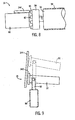
- FIGURE 8 is a side view of the drive assembly of a treadmill in accordance with an alternative preferred embodiment of the present invention.
- FIGURE 9 is a side view of the lift assembly of a treadmill in accordance with an alternative preferred embodiment of the present invention.
- an exercise machine specifically a treadmill
- the present invention is also applicable to other types of exercise machines, such as, for example, an elliptical exercise machine, a stair stepper and a cycling machine.
- the treadmill 10 includes a frame 12, operably supporting a deck assembly 14, a drive assembly 16, a lift assembly 18 and a control system 20.
- the frame 12 preferably includes first and second longitudinally extending sides 22 and 24, at least a pair of upwardly extending posts 26 interconnected at an upper end to a support plate 28, which generally spans the width of the deck assembly 14 and supports the control system 20, or a portion thereof.
- the frame 12 further includes a cross bar 30 upwardly extending from each side of the deck assembly 14 and extending across the deck assembly 14 adjacent the support plate 28.
- the frame 12 is formed of a tough, rigid, durable material, preferably steel with a rust-resistant, multi-layered powder coating.
- the frame can be formed of other materials, such as, for example, other metals, composite materials, and combinations thereof.
- the frame 12 can be configured with or without one or more upwardly extending posts, and with or without one or more upwardly extending cross bars.
- the deck assembly 14 includes a deck 32, at least first and second substantially parallel rollers 34 and 36 and an endless belt 38 extending around the first and second rollers 34 and 36 and over the deck 32.
- the deck 32 is a generally rectangular, longitudinally extending planar structure disposed between the first and second sides 22 and 24 of the frame 12, and adjacent to the first and second rollers 34 and 36.
- the deck 32 provides a running or walking surface beneath, and supporting, the portion of the belt 38 extending over the upper surface of the deck 32.
- the deck 32 is formed of a durable, generally resilient material, preferably a high density fiberboard core laminated with a phenolic laminate. Alternatively, the deck can be formed of other materials, such as, for example, plywood, and other fiberboard compositions.
- the deck 32 is configured to deflect as the user moves and transfers his or her weight to different parts of the deck. For example, if the user is running and plants his or her left foot down at the top left corner of the deck, maximum deflection will occur there and to a lesser extent elsewhere.
- the first and second rollers 34 and 36 extend between and rotatably couple to the first and second sides 22 and 24 of the frame 12 at front and rear portions of the frame 12, respectively.
- the endless belt 38 longitudinally extends along the upper surface of the deck 32 around a portion of the first roller 34, back through the frame 12, and around a portion of the second roller 36 to form a closed endless loop.
- the width of the belt 38 is preferably generally equal to, or slightly less than, the width of the deck 32.
- the belt 38 is formed of a resilient, durable material, preferably a multi-weave polyester.
- the belt can be formed of other materials, such as, for example, other elastomeric materials and other polymers.
- the shape of the deck assembly when viewed along a vertical longitudinal plane, is generally arcuate.
- the deck assembly 14 further includes at least one deck deflection sensor 40 positioned adjacent to the lower surface of the deck 32.
- the deck assembly 14 preferably includes six deck deflection sensors 40 positioned in spaced about locations adjacent to the lower surface of the deck 32. In alternative preferred embodiments, other numbers of deck deflection sensors in spaced apart locations on, about, or beneath, the deck 32 can be used.
- the deck deflection sensor 40 is a displacement sensor configured to measure deck deflection in a contactless or contact-free manner.
- the deck deflection sensor 40 is configured to measure the movement or deflection of the deck 32 caused by application of a user's foot during walking, running or standing on the treadmill 10.
- the deflections resulting from walking or running on the treadmill 10 form a unique pattern according to the engineer's plate bending theory for a given amount of loading at a particular point.
- the deck deflection sensor 40 includes an electrical intermediate device 42 and an aerial 44.
- the intermediate device 42 is an indicating element or target, whose displacement alters the electrical inductance between the windings of the aerial 44.
- the intermediate device 42 includes a passive resonant circuit.
- the intermediate device 42 comprises a resonant "LC" circuit including an inductance (L) 46 in the form of a coil of conductive tracks or wires, and a capacitor (C) 48, in series.
- the coil of the inductance 46 is formed as a series of spiralled tracks on a printed circuit board 50 and the capacitor 48 soldered in series with the tracks.
- the intermediate device 42 is preferably removably connected to the lower surface of the deck 32, and positioned adjacent to the aerial 44, preferably within 0.1 to 100 mm of the aerial 44.
- the intermediate device 42 can be fixedly secured to the deck, coupled to the deck, or placed directly adjacent to the deck.
- the sensor is substantially similar to the sensing apparatus described in UK Patent Application No. GB 2374424 filed on July 31, 2002 .
- the LC circuit of the intermediate device 42 has a natural resonant frequency in the range 100kHz to 10MHz for good levels of signal coupling without the requirement for expensive, high frequency electronics.
- the intermediate device 42 can be formed with other natural resonant frequency ranges.
- the intermediate device can be a conductive metal target or ferrite slug.
- An LC resonant circuit is preferred however due to the resultant increased signal amplitude, signal quality factor and signal to noise ratio associated with the LC resonant circuit.
- the previously described electrically passive intermediate device 42 can be an electrically active component powered by a power supply such as a battery. Such an electrically active embodiment is preferable if the distance between the intermediate device and the aerial exceeds 100 mm.
- the aerial 44 is a sensing unit, which includes an arrangement of transmit windings 52 and receive windings 54.
- the aerial 44 is has a generally planar shape.
- the aerial 44 can be formed in other shapes to suit the specific mechanical geometry of the it's location and, in particular, the location and motion of the intermediate device 42, such as, for example, a cylindrical shape, a curved shape forming part of a cylinder, a hemi-spherical shape and an arcuate shape.
- the transmit and receive windings 52 and 54 are preferably formed as tracks on a multi-layer printed circuit board 56.
- Each aerial 44 preferably has a separate, single intermediate device 42 corresponding to it during operation. Alternatively, two or more intermediate devices 42 of substantially differing resonant frequencies can be used with a single aerial 44.
- the aerials 44 are operably coupled to the control system 20, and mechanically coupled to the frame 12 at locations adjacent to the intermediate device 42.
- the aerials 44 can be connected to the frame 12 through mechanical fasteners, adhesives, or other conventional fastening means.
- the aerial 44 is preferably positioned within 0.1 to 100 mm from the intermediate device 42. In other preferred embodiments the distance between the aerial 44 and the intermediate device 42 can be greater than 100 mm.
- the transmit windings 52 are energised with an alternating electrical signal supplied through the control system 20, so as to produce a local alternating electromagnetic field 58.
- deflection of the deck 32 causes the intermediate device 42 to move downward relative to the aerial 44 and within the limits of minimum and maximum deck deflection.
- the alternating magnetic field 58 is preferably at substantially the same frequency as the resonant frequency of the intermediate device 42.
- the intermediate device 42 moves along the alternating electromagnetic field causing the mutual inductance between the transmit windings 52 and receive winding 54 to vary in relation to the deck deflection.
- the accuracy of the signal produced by the receive windings 54, and corresponding to the deck deflection, is generally not negatively affected by variations in the stand-off distance within the allowed range of 0.1 to 100 mm.
- the stand-off distance is the 0.1 to 100 mm distance separating the intermediate device 42 from the aerial 44. Accordingly, referring to FIG. 3 , as the intermediate device 42 moves relative to the aerial 44 in a direction, y, along the aerial 44, variation in the stand-off distance, x, between 0.1 to 100 mm, does not negatively affect the deck deflection measurement taken along the direction, y.
- the intermediate device can be coupled to the frame and the aerial can be coupled to the deck such that upon application of a load onto the deck, the aerial moves downward relative to the intermediate device.
- FIG. 4 illustrates the intermediate device 42, as a resonant circuit, cooperating with an arrangement of the transmit and receive windings 52 and 54.
- the transmit windings 52 are arranged as a first and second electrically separate generally sinusoidal and cosinusoidally or 90 degree phase shifted wound circuits 52a and 52b which are formed on two layers of the printed circuit board 56 over a pitch or wavelength L.
- the transmit windings can be configured in other phased intersecting arrangements.
- the printed circuit board 56 is conductively plated through holes to form the inter-layer electrical connections for each winding.
- the printed circuit board 56 of the transmit and receive windings 52 and 54 and the printed circuit board 50 of the intermediate device 42 include photo-etched copper tracks or printed conductive tracks on an insulating substrate.
- simple windings of conductive wire or cable with an insulated cover are also feasible.
- printed circuit boards are preferable due to their ease and low cost of manufacture relative to high accuracy.
- the receive windings 54 are formed as a simple loop extending along and around the transmit windings 52.
- the shape of the loop formed by the receive windings 54 is preferably generally rectangular.
- the shape of the loop can be generally oval, circular, polygonal and irregular. It will be obvious to those skilled in the art that yet other arrangements are also feasible.
- the intermediate device 42 is preferably positioned to be substantially parallel to, and within 0.1 to 100 mm of, the transmit and receive windings 52 and 54 of the aerial 44. Alternatively, the intermediate device 42 may move normally to the transmit and receive windings 52 and 54. In such arrangements an alternative sensing algorithm to that previously described is required. For example, an alternative algorithm would be to correlate the variation in received signal amplitude to relative displacement.
- the control system 20 is shown in greater detail.
- the control system 20 is operably coupled to the deck deflection sensors 40, the drive assembly 16 (see FIG. 2 ), and the incline assembly 18 (see FIG. 2 ), and controls the operation of the drive and incline assemblies 16 and 18.
- a power supply is electrically coupled to, and energizes, the control system 20, the deck deflection sensors 40, the drive assembly 16 and the incline assembly 18.
- the control system 20 includes a frequency generator 60, a set of receive electronics 62, a micro-controller 64, and a display panel 66.
- the components of the control system 20 are preferably positioned at multiple locations about the frame 12.
- the display panel 66 is positioned on the support plate 28 (see FIG.
- the control system 20 has a single micro-controller 64 (or microprocessor), a single frequency generator 60, a single set of receive electronics 62, and a single display panel 66. If a single micro-controller or microprocessor is used, sufficient bandwidth must be available for the micro-controller or microprocessor to carry out frequent deck deflection measurements without interrupting the operation of other control system functions performed by the miccro-controller or microprocessor.
- each deck deflection sensor 40 has its own dedicated micro-controller or microprocessor, or any combination of one or more frequency generators, sets of receive electronics, micro-controllers, and displays.
- the frequency generator 60 provides an alternating electrical signal to the transmit windings 52 to produce the local alternating electromagnetic field 58, which is substantially the same frequency as the resonant frequency of the intermediate device 52.
- the alternating transmit signals energizing the transmit windings 52 are generated using an oscillating circuit source, preferably a 16 or 32 MHz crystal oscillating circuit source, reduced down to suit the resonant frequency of the intermediate device 42, and fed in to the transmit windings 52 via the control system 20. Power sources of other sizes and types can also be used.
- the frequency generator 60 produces first and second phase shifted signals 68 and 70 to the first and second wound circuits 52a and 52b of the transmit windings 52.
- the electric signals of the frequency generator 60 produce a mutual inductance between the transmit and receive windings 52 and 54.
- the intermediate device 42 moves relative to the aerial 44, due to the deflection of the deck 32, the mutual inductance between the transmit and receive windings 52 and 54 varies in relation to the amount of deck deflection.
- the control system 20, including the set of receive electronics 62 and the micro-controller 64, is preferably also capable of comparing the combined received signals from the receive windings 54, with the voltage and phase of the transmitted signals of the transmit windings 52, such that the variation according to the actual position of the intermediate device 42 can be calculated against a preset or theoretical variation of mutual inductance.
- the set of receive electronics 62 includes a phase detector 72 and a position calculator 74.
- the output of the set of receive electronics 62, in particular the output of the position calculator 74, is operably coupled to the microcontroller 64 and the display 66.
- the control system 20 is configured to process the signals of the deck deflection sensors 40 and to utilize the deck deflection information in a variety of useful ways.
- the deck deflection sensor(s) 40 can be used to automatically measure the weight of a user positioned on the deck of the treadmill.
- the automatic weight calculation eliminates the need for the user to manually enter his or her estimated weight into the control system 20 of the treadmill before commencing operation of the treadmill.
- the automatic calculation of user weight also eliminates the error associated with the user's estimate of his or her own weight.
- the user weight information can then be used for calculating information relating to the user's workout or for use in setting other machine parameters such as resistance level.
- control system 20 can include a first predetermined deflection or weight setpoint.
- the control system 20 is then configured to prevent the treadmill 10 from operating unless the weight of the user meet or exceeds the first predetermined setpoint.
- the first predetermined setpoint can be a fixed value, or a value that can be adjusted as necessary.
- the first predetermined setpoint is configured to correlate to a minimum weight of a user. Accordingly, the first predetermined setpoint can be set at any predetermined weight value to accomplish the desired inadvertent start prevention feature.
- the first predetermined setpoint corresponds to a user weight of 30 pounds.
- the predetermined setpoint can be set to correspond to other weight settings, such as, for example, 40 pounds, 50 pounds, and 60 pounds. The first predetermined setpoint, therefore, prevents the inadvertent actuation of the machine by a small child, and virtually eliminates the risk of a small child climbing onto a treadmill deck and activating the treadmill.
- control system 20 can include a second predetermined deflection or weight setpoint.
- the second predetermined setpoint is configured to cease or terminate operation of the treadmill if the weight of the user on the treadmill drops below the second predetermined setpoint for a first predetermined amount of time.
- the second predetermined setpoint can be set to correspond to a weight below that of a typical user. In one particularly preferred embodiment, the second predetermined setpoint corresponds to a user weight of 70 pounds. In alternative particularly preferred embodiments, the second predetermined setpoint can be set to correspond to other weight settings, such as, for example, 60 pounds, 50 pounds, and 40 pounds.
- the second predetermined setpoint can be set as a percentage of the particular user's weight, such as, for example, 80 percent of the user's weight, 70 percent of the user's weight, etc. As an example, if the second predetermined setpoint is set at 70 percent of the user's weight, if a user weighing 200 pounds leaves an operating machine, if the weight on the deck 32 of the treadmill remains less than 140 pounds for the duration of first predetermined time period, the control system 20 will cease the operation of the treadmill 10.
- the first predetermined time period can be fixed or adjusted as necessary. In one particularly preferred embodiment, the first predetermined time period is five seconds. In other particularly preferred embodiments, other time periods can be used, such as, for example, 2 seconds, 3 seconds, and 10 seconds.
- This automatic shutdown feature will automatically shutdown the treadmill 10, in the event the user falls from the treadmill, or leaves the treadmill without shutting the treadmill down. Thus, if the user leaves the treadmill 10 without shutting the treadmill down, the deflection sensors 40 will detect the reduction, or absence of, deck deflection (or user weight) and produce a corresponding signal to the control system 20.
- the control system will automatically shutdown the treadmill 10, or simply stop the movement of the belt 32 of the treadmill 10 and place the controls in a standby mode.
- control system 20 can be configured to differentiate between the deck deflection sensors 40 and to determine the impact pattern of the user's feet on the deck 32. Such information can be used to adjust the speed or incline of the machine, or to warn the user that user is operating the treadmill at a location too close to either side edge of the belt of the treadmill. Such impact pattern information can also be used to perform stride length calculations and diagnostics.
- FIG. 6 shows a schematic of an example trace from 4 deck deflection sensors showing deflection (X) over time (t).
- the vertical offset of the various traces is shown for reasons of clarity.
- the four sensors are arranged at four locations around or under the deck - front left, front right, rear left and rear right.
- Such an arrangement is only one of many possible arrangements, which may be deployed for maximum data with more sensors or maximum economy with fewer sensors. From the example arrangement it is possible to differentiate between impacts made by the user's left and right leg; left leg produces greater deflection on the front left sensor compared to smaller but concurrent deflection of the front right sensor and vice versa. Further, it is also possible to infer the user's lateral or longitudinal position by comparing impacts or deflections from each of the various sensors. Such longitudinal information is particularly valuable as it provides data to enable automatic motor speed control; speeding up as the user nears the front of the machine or slowing down as the user nears the back of the belt.
- the number of impacts over a given time can be calculated and compared with the distance travelled by the belt and hence data on stride length or stride pattern compared to the speed and incline of the machine can usefully be generated for diagnosis of the user's performance.
- the deck deflection sensors of the present invention enable deck deflection of the treadmill to be measured in an accurate, reliable, a relatively inexpensive and non-complex manner.
- the deck deflection sensors of the present invention are significantly less expensive than other commonly used instruments, such as, linear differential transformers, ultrasonic sensors, and optical sensors. Because the non-contact deflection sensors of the present invention are not negatively affected by variations in the stand-off distance within 0.1 to 100 mm, the tolerances of the components supporting the intermediate device and aerial of the deflection sensor do not have to be as tightly maintained as required by many existing conventional sensors.
- the position of a user on the treadmill 10 is sensed using at least one aerial 144 and at least one electrical intermediate device 142.
- the aerial 144 is substantially the same as the aerial 44.
- the aerial 144 is coupled to the deck 32, preferably in a position that is substantially coplanar with the deck 32.
- the aerial 144 also preferably extends over substantially the entire usable portion of the deck 32.
- the aerial 144 is mounted to the lower surface of the deck 32.
- the aerial can be disposed within the deck or in a position adjacent to and substantially parallel with, the deck.
- multiple aerials can be employed in a spaced apart arrangements about the deck.
- the aerial 144 like the aerial 44 includes an arrangement of transmit and receive windings 152 and 154, which are substantially similar to the windings 52 and 54.
- the aerial 144 is operably coupled to the control system 20.
- the electrical intermediate device 142 is substantially the same as the intermediate device 42. Referring to FIG. 6 , in one particularly preferred embodiment, a separate electrical intermediate device 142 is coupled to each leg of the user.
- the intermediate device 142 can be attached to the user's shoe, ankle (such as through an ankle strap), lower leg, or knee (such as through a knee strap).
- the intermediate device 142 causes the mutual inductance between the transmit windings 152 and the receive windings 154 to vary in relation to the location of the intermediate device 142 on the deck 32.
- the control system 20 monitors the mutual inductance from the windings 152 and 154 of the aerial 144 to identify the position of the user on the treadmill. Based upon these signals, or variations in the mutual inductance, the control system can determine the user's position, including fore and aft as well as right and left.
- the control system 20 can be configured to emit audible warning signals to the user based upon the user's position.
- the audible signals can be generated directly from the control system 20 or from one or more speakers (not shown), or other sound generating device, mounted in the treadmill. For example, if the user drifts too far to the right of the treadmill during use, the treadmill 10 can emit a first audible warning signal to alert the user to change his or her position. Similarly, if the user drifts too far to the left of the treadmill during use, the treadmill 10 can emit a second audible warning signal. Likewise, if the user is too forward or rearward on the deck the treadmill can emit third and/or fourth audible warning signals to alert the user.
- the audible warning signals can be specific tones, or specific voice warnings. Such a configuration, would be of particular benefit to blind users who can rely on the audible warning signals to maintain proper position on the treadmill.
- the fore and aft positions of the user on the deck 32 can be used to adjust the speed the treadmill 10.
- the control system 20, which is coupled to the drive assembly 16, can cause the speed to increase if the user is in a forward position on the deck, and decrease if the user is in a rearward position on the deck 32.
- the user's position on the treadmill 10 can be used to automatically control the speed of the treadmill 10.
- the control system 20 can be configured to increase the speed of the treadmill 10, if the user takes a position toward the right side of the deck 32, or decrease the speed, if the user takes a position toward the left side of the deck 32 during use. This right/left speed adjustment configuration may be more suited for shorter length treadmills.
- the aerial 144 and intermediate devices 142 can also be used to enable the user to automatically adjust or control the incline of the deck 32 by varying the user's position on the treadmill 10 during use.
- the control system 20 can be configured to induce the lift assembly 18 raise the forward portion of the deck 32, or increase the angle of incline of the deck 32, if the user takes a forward position on the deck 32.
- the control system 20 cause the lift assembly 18 to automatically lower the incline of the deck 32, if the user takes a rearward position on the deck 32.
- the present invention using inductive position sensing, provides a reliable, cost effective means of automatically controlling or adjusting the operation of a treadmill. Further, the present invention doesn't require additional mounting of equipment onto handrails or displays of the treadmill.
- An aerial 244 is supported by the frame or other structure of the treadmill, and is positioned adjacent to a rotating component of the treadmill 10, to function as a contactless speed sensor.
- the aerial 244 is substantially the same as the aerial 44 and includes an arrangement of transmit and receive windings, which are substantially the same as the windings 52 and 54.
- the aerial 244 is positioned adjacent to the drive assembly 16, which includes a motor 80, an output shaft 82, and a flywheel 84.
- the motor 80 is electrically coupled to the control system 20 and to a power supply, and directly connected to the output shaft 82.
- the output shaft 82 is coupled to the flywheel 84 and to one of the rollers 34.
- the motor 80 causes the output shaft 82, as well as the flywheel 84 and the roller 34 to rotate, thereby driving the belt 38 of the treadmill 10.
- the flywheel 84 includes at least one outwardly projecting constellation 86, and preferably a plurality of constellations 86.
- the flywheel 84 is positioned adjacent the aerial 244 such that the constellations 86 act as one or more electrical intermediate devices.
- the rotational movement of the constellations about the aerial 244 causes a variation in the mutual inductance of the transmit and receive windings 252 and 254 of the aerial 244.
- the control system 20 monitors this variation of mutual inductance to determine the rotational speed of the flywheel 84 and the shaft 82.
- the aerial can be positioned to other rotational members of the treadmill including the rotor of the motor, the output shaft, or one of the rollers.
- the electrical intermediate device can be other conductive metal targets, a ferrite slug, a resonant LC circuit, or an electrically active component powered by a battery.
- the contactless configuration of this speed sensing aerial provides a low cost, reliably and accurate means of monitoring the speed of the treadmill without producing undesirable drag or resistance on the drive assembly.
- An aerial 344 is supported by the frame or other structure of the treadmill, and is positioned adjacent to a forward end 90 of the deck assembly 14, to function as a contactless incline sensor.
- the aerial 344 is substantially the same as the aerial 44 and includes an arrangement of transmit and receive windings, which are substantially the same as the windings 52 and 54.
- the aerial 244 is positioned adjacent to the lift assembly 18, which includes a lift actuator 92 and an actuating arm 94.
- the lift actuator 92 is electrically coupled to the control system 20 and to a power supply.
- the actuating arm 94 is coupled to the forward end 90 of the deck assembly 14. In operation, the lift actuator 92 causes displacement of the actuating arm 94 which raises or lowers the height of the forward end 90, thereby varying the incline, of the deck assembly 14.
- An electrical indicating device 342 is coupled to the forward end 90. Like the intermediate device 42, the intermediate device 342 causes the mutual inductance between the transmit and receive windings to vary in relation to the location of the intermediate device 342 relative to the frame 12.
- the control system 20 monitors the mutual inductance from the windings of the aerial 344 to identify the position of the forward end 90 of the deck assembly 14. Based upon these signals, or variations in the mutual inductance, the control system 20 can determine the incline of the deck assembly 14.
- the control system 20 can be configured with a single micro-controller 64 (or microprocessor), a single frequency generator 60, a single set of receive electronics 62 for processing the signals or variation in inductance in the winding of one, two or all of the aerials 44, 144, 244 and 344 of the treadmill 10.
- each aerial 44, 144, 244 or 344, or group of 2 or more aerials can have its own dedicated micro-controller or microprocessor, or any combination of one or more frequency generators, sets of receive electronics, micro-controllers, and displays.
Landscapes
- Health & Medical Sciences (AREA)
- Cardiology (AREA)
- Vascular Medicine (AREA)
- General Health & Medical Sciences (AREA)
- Physical Education & Sports Medicine (AREA)
- Rehabilitation Tools (AREA)
Claims (76)
- Laufband mit einem Rahmen (12); einem Laufflächenaufbau (14), welcher durch den Rahmen (12) getragen wird, wobei der Laufflächenaufbau (14) eine sich in Längsrichtung erstreckende Lauffläche (32), wenigstens eine erste und eine zweite Walze (34, 36) und ein Band (38), das über der Lauffläche (32) und der ersten und zweiten Walze (34, 36) positioniert ist, umfasst, wobei das Laufband gekennzeichnet ist durch:wenigstens einen Sensor, welcher mit der Lauffläche (32) gekoppelt ist, wobei der Sensor ein kontaktloser Verschiebungssensor ist, der ein elektrisches Übertragungsglied (42) und eine nichtzylindrische Anordnung von Übertragungs- und Empfangswicklungen (52, 54) umfasst, wobei relative Bewegung zwischen dem Übertragungsglied (42) und der Anordnung eine Veränderung in der gegenseitigen Induktivität zwischen den Übertragungs- und Empfangswicklungen (52, 54) erzeugt; undein Steuersystem (20), welches betriebsfähig mit dem wenigstens einen Sensor gekoppelt ist, wobei das Steuersystem (20) konfiguriert ist, um elektrisch die Veränderung in der gegenseitigen Induktivität der Übertragungs- und Empfangswicklungen (52, 54) zu messen und in eine Verschiebungsmessung zu wandeln.
- Laufband gemäß Anspruch 1, wobei der wenigstens eine Laufflächensensor (40) aus wenigstens zwei Laufflächensensoren besteht, welche an beabstandeten Stellen um die Lauffläche (32) herum positioniert sind.
- Laufband gemäß Anspruch 1, wobei der wenigstens eine Laufflächensensor (40) aus wenigstens vier Laufflächensensoren besteht, welche an beabstandeten Stellen um die Lauffläche (32) herum positioniert sind.
- Laufband gemäß Anspruch 1, wobei der wenigstens eine Laufflächensensor (40) aus wenigstens sechs Laufflächensensoren besteht, welche an beabstandeten Stellen um die Lauffläche (32) herum positioniert sind.
- Laufband gemäß Anspruch 1, wobei das elektrische Übertragungsglied (42) aus der Gruppe ausgewählt ist, bestehend aus: einem passiven elektrischen Schwingkreis, einem mit Energie versorgten elektrischen Schwingkreis, einem LC-Schwingkreis, einem leitenden Metallkörperchen und einem leitenden Ferritkörperchen.
- Laufband gemäß Anspruch 1, wobei die nichtzylindrische Anordnung der Übertragungs- und Empfangswicklungen (52, 54) eben ist.
- Laufband gemäß Anspruch 1, wobei die nichtzylindrische Anordnung der Übertragungs- und Empfangswicklungen (52, 54) eine Antenne ist und wobei die Gestalt der Antenne aus der Gruppe ausgewählt ist, bestehend aus einer gebogenen Form, welche einen Teil eines Zylinders aufweist, einer halbkugeligen Form und einer gekrümmten Form.
- Laufband gemäß Anspruch 1, wobei das elektrische Übertragungsglied (42) einen LC-Schwingkreis umfasst und wobei der Abstand, welcher die Vorrichtung und die Anordnung der Übertragungs- und Empfangswicklungen (52, 54) trennt, im Bereich von 0,1 bis 100 mm liegt.
- Laufband gemäß Anspruch 8, wobei die Trennung zwischen dem elektrischen Übertragungsglied (42) und der Antenne entlang einer ersten Richtung gemessen wird und wobei, wenn sich das elektrische Übertragungsglied (42) in Bezug auf die Antenne in eine zweite Richtung bewegt, die unterschiedlich zur ersten Richtung ist, die Genauigkeit des Laufflächensensors (40) nicht bedeutsam negativ durch Veränderungen im Trennungsabstand zwischen 0,1 und 100 mm beeinflusst wird.
- Laufband gemäß Anspruch 1, wobei das Steuersystem (20) so konfiguriert ist, um das Laufband automatisch abzuschalten, wenn das Signal, welches durch den Laufflächensensor (40) erzeugt wird, unter einen vorbestimmten Wert für einen vorbestimmten Zeitraum fällt.
- Laufband gemäß Anspruch 10, wobei der vorbestimmte Wert des Signals, welches durch den Laufflächensensor (40) erzeugt wird, einem Gewicht von weniger als 31,8 kg (70 lbs) entspricht.
- Laufband gemäß Anspruch 10, wobei der vorbestimmte Wert des Signals, welches durch den Laufflächensensor (40) erzeugt wird, einem Gewicht von weniger als 27,3 kg (60 lbs) entspricht.
- Laufband gemäß Anspruch 10, wobei der vorbestimmte Wert des Signals, welches durch den Laufflächensensor (40) erzeugt wird, einem Gewicht von weniger als 22,7 kg (50 lbs) entspricht.
- Laufband gemäß Anspruch 10, wobei der vorbestimmte Zeitraum kleiner als oder gleich fünf Sekunden ist.
- Laufband gemäß Anspruch 1, wobei der wenigstens eine Laufflächensensor (40) eine Mehrzahl von beabstandeten Laufflächendurchbiegungssensoren ist, wobei jeder Laufflächendurchbiegungssensor ein Signal erzeugt, welches für die Durchbiegung eines getrennten Bereichs der Lauffläche (32) steht, und wobei das Steuersystem (20) konfiguriert ist, um die Signale von den Laufflächensensoren zu verarbeiten und um zwischen den Laufflächensensoren zu unterscheiden.
- Laufband gemäß Anspruch 15, wobei das Steuersystem (20) konfiguriert ist, um besondere Betriebsmerkmale eines Benützers des Laufbandes auf der Grundlage der Signale von den Laufflächensensoren von getrennten Bereichen der Lauffläche (32) zu bestimmen.
- Laufband gemäß Anspruch 16, wobei die Betriebsmerkmale aus der Gruppe ausgewählt sind, bestehend aus der Schrittlänge, der Geschwindigkeit des Benützers, des Auftrittmusters auf der Lauffläche des Benützers, schrittdiagnostischen Merkmalen, der seitlichen Position des Benützers, der Position in Längsrichtung des Benützers und der Verbindung derselben.
- Laufband gemäß Anspruch 16, des Weiteren umfassend einen Antriebsaufbau, welcher mit einer der Walzen (34, 36) und dem Steuersystem (20) gekoppelt ist, wobei das Steuersystem (20) ein Geschwindigkeitssignal an den Antriebsaufbau ausgibt, um die Geschwindigkeit des Bandes (38) anzupassen, welches auf wenigstens einem Betriebsmerkmal des Benützers basiert.
- Laufband gemäß Anspruch 1, wobei das Steuersystem (20) automatisch das Gewicht des Benützers auf Grundlage der Durchbiegung des wenigstens einen Sensors (40) berechnet.
- Laufband gemäß Anspruch 1, wobei das Steuersystem (20) so konfiguriert ist, um das Laufband daran zu hindern betrieben zu werden, bis das Signal, welches von dem wenigstens einen Laufflächensensor (40) empfangen wird, eine vorbestimmte Größenordnung übersteigt.
- Laufband gemäß Anspruch 20, wobei die vorbestimmte Größenordnung des Signals einem Gewicht von wenigstens 13,6 kg (30 lbs) entspricht.
- Laufband gemäß Anspruch 20, wobei die vorbestimmte Größenordnung des Signals einem Gewicht von wenigstens 18,2 kg (40 lbs) entspricht.
- Laufband gemäß Anspruch 20, wobei die vorbestimmte Größenordnung des Signals einem Gewicht von wenigstens 22,7 kg (50 lbs) entspricht.
- Laufband gemäß Anspruch 20, wobei der wenigstens eine Laufflächensensor (40) aus wenigstens zwei Laufflächensensoren besteht, welche an beabstandeten Stellen um die Lauffläche (32) herum positioniert sind.
- Laufband gemäß Anspruch 20, wobei der wenigstens eine Laufflächensensor (40) aus wenigstens vier Laufflächensensoren besteht, welche an beabstandeten Stellen um die Lauffläche (32) herum positioniert sind.
- Laufband gemäß Anspruch 20, wobei der wenigstens eine Laufflächensensor (40) aus wenigstens sechs Laufflächensensoren besteht, welche an beabstandeten Stellen um die Lauffläche (32) herum positioniert sind.
- Laufband gemäß Anspruch 20, wobei der Laufflächensensor (40) ein kontaktloser Verschiebungssensor ist, welcher ein elektrisches Übertragungsglied (42) und eine Antenne umfasst.
- Laufband gemäß Anspruch 27, wobei das elektrische Übertragungsglied (42) aus der Gruppe ausgewählt ist, bestehend aus: einem passiven elektrischen Schwingkreis, einem mit Energie versorgten elektrischen Schwingkreis, einem LC-Schwingkreis, einem leitenden Metallkörperchen und einem leitenden Ferritkörperchen.
- Laufband gemäß Anspruch 27, wobei die Antenne eine Übertragungswicklung und eine Empfangswicklung umfasst.
- Laufband gemäß Anspruch 27, wobei die Gestalt der Antenne aus der Gruppe ausgewählt ist, bestehend aus einer im Wesentlichen ebenen Form, einer gebogenen Form, welche einen Teil eines Zylinders aufweist, einer halbkugeligen Form und einer gekrümmten Form.
- Laufband gemäß Anspruch 27, wobei das elektrische Übertragungsglied (42) einen LC-Schwingkreis umfasst und wobei der Abstand, welcher die Vorrichtung und die Antenne trennt, im Bereich von 0,1 bis 100 mm liegt.
- Laufband gemäß Anspruch 31, wobei die Trennung zwischen dem elektrischen Übertragungsglied (42) und der Antenne entlang einer ersten Richtung gemessen wird und wobei, wenn sich das elektrische Übertragungsglied (42) in Bezug auf die Antenne in eine zweite Richtung bewegt, die unterschiedlich zur ersten Richtung ist, die Genauigkeit des Laufflächensensors (40) nicht bedeutsam negativ durch Veränderungen im Trennungsabstand zwischen 0,1 und 100 mm beeinflusst wird.
- Laufband gemäß Anspruch 1, dadurch gekennzeichnet, dass das Laufband so konfiguriert ist, um das Gewicht eines Benützers zu bestimmen und wobei wenigstens ein Sensor (40) mit der Lauffläche (32) gekoppelt ist, so dass das Anlegen des Gewichts des Benützers auf den Laufflächenaufbau (14) die Veränderung in der gegenseitigen Induktivität zwischen den Übertragungs- und Empfangswicklungen (52, 54) erzeugt.
- Laufband gemäß Anspruch 33, wobei der wenigstens eine Laufflächensensor (40) aus wenigstens vier Laufflächensensoren besteht, welche an beabstandeten Stellen um die Lauffläche (32) herum positioniert sind.
- Laufband gemäß Anspruch 33, wobei der wenigstens eine Laufflächensensor (40) aus wenigstens sechs Laufflächensensoren besteht, welche an beabstandeten Stellen um die Lauffläche (32) herum positioniert sind.
- Laufband gemäß Anspruch 33, wobei der wenigstens eine Laufflächensensor (40) des Weiteren ein elektrisches Übertragungsglied (42) umfasst, welches aus der Gruppe ausgewählt ist, bestehend aus: einem passiven elektrischen Schwingkreis, einem aktiven elektrischen Schwingkreis, einem LC-Schwingkreis, einem leitenden Metallkörperchen und einem leitenden Ferritkörperchen.
- Laufband gemäß Anspruch 33, wobei die Übertragungs- und Empfangswicklungen (52, 54) des Laufflächensensors (40) als eine Antenne ausgebildet sind und wobei die Gestalt der Antenne aus der Gruppe ausgewählt ist, bestehend aus einer im Wesentlichen ebenen Form und einer gebogenen Form, welche einen Teil eines Zylinders aufweist.
- Laufband gemäß Anspruch 36, wobei das elektrische Übertragungsglied (42) einen passiven elektrischen Schwingkreis umfasst und wobei der Abstand, welcher die Vorrichtung und die Antenne trennt, im Bereich von 0,1 bis 100 mm liegt.
- Laufband gemäß Anspruch 38, wobei die Trennung zwischen dem elektrischen Übertragungsglied (42) und der Antenne entlang einer ersten Richtung gemessen wird und wobei, wenn sich das elektrische Übertragungsglied (42) in Bezug auf die Antenne in eine zweite Richtung bewegt, die unterschiedlich zur ersten Richtung ist, die Genauigkeit des Laufflächensensors (40) nicht bedeutsam negativ durch Veränderungen im Trennungsabstand zwischen 0,1 und 100 mm beeinflusst wird.
- Laufband gemäß Anspruch 33, wobei das Steuersystem (20) konfiguriert ist, um das Laufband automatisch abzuschalten, wenn die Laufflächenverschiebungsmessung, welche durch den Laufflächensensor (40) erzeugt wird, unter einen ersten vorbestimmten Wert für einen vorbestimmten Zeitraum fällt.
- Laufband gemäß Anspruch 40, wobei der erste vorbestimmte Wert einem Gewicht von weniger als 31,8 kg (70 lbs) entspricht.
- Laufband gemäß Anspruch 40, wobei der erste vorbestimmte Wert einem Gewicht von weniger als 22,7 kg (50 lbs) entspricht.
- Laufband gemäß Anspruch 40, wobei der vorbestimmte Zeitraum weniger oder gleich fünf Sekunden beträgt.
- Laufband gemäß Anspruch 33, wobei das Steuersystem (20) so konfiguriert ist, um das Laufband daran zu hindern betrieben zu werden, bis die Laufflächenverschiebungsmessung, welche vom Laufflächensensor (40) erzeugt wird, einen zweiten vorbestimmten Wert übersteigt.
- Laufband gemäß Anspruch 44, wobei der zweite vorbestimmte Wert einem Gewicht von wenigstens 13,6 kg (30 lbs) entspricht.
- Laufband gemäß Anspruch 44, wobei der zweite vorbestimmte Wert einem Gewicht von wenigstens 22,7 kg (50 lbs) entspricht.
- Laufband gemäß Anspruch 33, wobei die Übertragungs- und Empfangswicklungen (52, 54) auf einer Leiterplatte ausgebildet sind.
- Laufband gemäß Anspruch 47, wobei die Übertragungswicklungen ein Paar elektrisch getrennter Kreise umfasst, welche in einer Anordnung ausgebildet sind, die aus der Gruppe ausgewählt ist, bestehend aus einer allgemeinen Sinus- und allgemeinen Cosinusanordnung, einer Schnittstellenanordnung und aus Kombinationen daraus.
- Laufband gemäß Anspruch 48, wobei die Empfangswicklungen eine allgemein geschlossene Schleife um die Übertragungswicklungen herum ausbilden und wobei die Gestalt der Schleife aus der Gruppe ausgewählt ist, bestehend aus rechteckig, oval, kreisförmig, polygonal und unregelmäßig.
- Laufband gemäß Anspruch 1, wobei die Übertragungswicklung konfiguriert ist, um sich unabhängig von den Empfangswicklungen bei Durchbiegung des Laufflächenaufbaus (14) zu bewegen.
- Laufband gemäß Anspruch 50, wobei der wenigstens eine Laufflächensensor (40) aus wenigstens zwei Laufflächensensoren besteht, welche an beabstandeten Stellen um die Lauffläche (32) herum positioniert sind.
- Laufband gemäß Anspruch 50, wobei der wenigstens eine Laufflächensensor (40) aus wenigstens vier Laufflächensensoren besteht, welche an beabstandeten Stellen um die Lauffläche (32) herum positioniert sind.
- Laufband gemäß Anspruch 50, wobei wenigstens eine der Übertragungswicklung und der Empfangswicklungen eben ist.
- Laufband gemäß Anspruch 50, wobei das Steuersystem (20) konfiguriert ist, um das Laufband automatisch abzuschalten, wenn das Signal, welches durch den Laufflächensensor (40) erzeugt wird, unter einen vorbestimmten Wert für einen vorbestimmten Zeitraum fällt.
- Laufband gemäß Anspruch 54, wobei der vorbestimmte Wert des Signals, welches durch den Laufflächensensor (40) erzeugt wird, einem Gewicht von weniger als 31,8 kg (70 lbs) entspricht.
- Laufband gemäß Anspruch 54, wobei der vorbestimmte Wert des Signals, welches durch den Laufflächensensor (40) erzeugt wird, einem Gewicht von weniger als 27,3 kg (60 lbs) entspricht.
- Laufband gemäß Anspruch 54, wobei der vorbestimmte Wert des Signals, welches durch den Laufflächensensor (40) erzeugt wird, einem Gewicht von weniger als 22,7 kg (50 lbs) entspricht.
- Laufband gemäß Anspruch 54, wobei der vorbestimmte Zeitraum weniger oder gleich fünf Sekunden beträgt.
- Laufband gemäß Anspruch 1, wobei das Steuersystem (20) konfiguriert ist, um ein alternierendes elektrisches Wahlsignal für die Übertragungswicklung bereit zu stellen, und wobei das Laufband des Weiteren durch Umfassen erster und zweiter Übertragungsglieder gekennzeichnet ist, welche jeweils an dem rechten und dem linken Bein des Benützers befestigt sind, wobei jedes Übertragungsglied (42) konfiguriert ist, um eine Veränderung in der gegenseitigen Induktivität zwischen den Übertragungs- und Empfangswicklungen (52, 54) als Reaktion auf eine Veränderung in der relativen Position des Übertragungsgliedes (42) zu den Wicklungen zu erzeugen.
- Laufband gemäß Anspruch 59, wobei die wenigstens eine Antenne direkt auf der Lauffläche (32) angebracht ist.
- Laufband gemäß Anspruch 59, wobei die wenigstens eine Antenne in der Lauffläche (32) positioniert ist.
- Laufband gemäß Anspruch 59, wobei jedes erste und zweite Übertragungsglied am Benützer an einer Stelle befestigt ist, welche aus der Gruppe ausgewählt ist, bestehend aus dem Schuh des Benützers, dem Knöchelbereich des Benützers, dem Unterschenkel des Benützers und dem Knöchel des Benützers.
- Laufband gemäß Anspruch 59, wobei die wenigstens eine Antenne aus wenigstens vier Antennen besteht, welche an beabstandeten Stellen um die Lauffläche (32) herum positioniert sind.
- Laufband gemäß Anspruch 59, wobei das erste und das zweite elektrische Übertragungsglied aus der Gruppe ausgewählt ist, bestehend aus: einem passiven elektrischen Schwingkreis, einem mit Energie versorgten elektrischen Schwingkreis, einem LC-Schwingkreis, einem leitenden Metallkörperchen und einem leitenden Ferritkörperchen.
- Laufband gemäß Anspruch 59, wobei das Steuersystem (20) konfiguriert ist, um die Auftrittsstellen des Fußes des Benützers auf der Lauffläche (32) auf der Grundlage der Veränderung der gegenseitigen Induktivität, welche zwischen der Übertragungs- und den Empfangswicklungen (52, 54) besteht, als Reaktion auf eine Veränderung in der relativen Position des Übertragungsgliedes (42) zu den Wicklungen zu bestimmen.
- Laufband gemäß Anspruch 65, des Weiteren umfassend einen Hebeaufbau und einen Antriebsaufbau, wobei sowohl der Hebeaufbau als auch der Antriebsaufbau betriebsbereit an das Steuersystem (20) gekoppelt sind.
- Laufband gemäß Anspruch 66, wobei das Steuersystem (20) konfiguriert ist, um eine Veränderung in der Geschwindigkeit des Laufbandes auf der Grundlage der Position des Benützers auf dem Laufband zu veranlassen.
- Laufband gemäß Anspruch 66, wobei das Steuersystem (20) konfiguriert ist, um eine Veränderung in der Steigung des Laufbandes auf der Grundlage der Position des Benützers auf dem Laufband zu veranlassen.
- Laufband gemäß Anspruch 65, wobei das Steuersystem (20) konfiguriert ist, um wenigstens ein hörbares Warnsignal auf der Grundlage der Position des Benützers auf dem Laufband zu erzeugen.
- Laufband gemäß Anspruch 59, wobei die Übertragungswicklungen ein Paar elektrisch getrennter Kreise umfassen, welche in einer Anordnung ausgebildet sind, die aus der Gruppe ausgewählt ist, bestehend aus einer allgemeinen Sinus- und allgemeinen Cosinusanordnung, einer Schnittstellenanordnung und aus Kombinationen daraus.
- Laufband gemäß Anspruch 1, dadurch gekennzeichnet, dass das Laufband des Weiteren umfasst:einen Antriebsaufbau, welcher an eine der beiden Walzen, erste und zweite Walze (34, 36) gekoppelt ist, wobei der Antriebsaufbau eine Mehrzahl von Komponenten umfasst, welche konfiguriert sind, um eine gemeinsame Achse während des Betriebs zu rotieren;wenigstens eine Antenne, welche an den Rahmen (12) gekoppelt ist und benachbart zu wenigstens einer der Komponenten des Antriebsaufbaus positioniert ist, wobei die Antenne eine nichtzylindrische Anordnung von Übertragungs- und Empfangswicklungen (52, 54) umfasst, wobei wenigstens eine der Komponenten konfiguriert ist, eine Veränderung in der gegenseitigen Induktivität zwischen den Übertragungs- und Empfangswicklungen (52, 54) während des Betriebs zu erzeugen, wenn die wenigstens eine Komponente relativ zur Antenne bewegt wird, wobei die Veränderung der gegenseitigen Induktivität, welche durch die relative Bewegung der wenigstens einen Komponente zur Antenne erzeugt wird, der Geschwindigkeit des Laufbandes entspricht.
- Laufband gemäß Anspruch 71, wobei die Komponenten des Antriebsaufbaus aus der Gruppe ausgewählt sind, bestehend aus einem Rotor, einer Abtriebswelle, einem Schwungrad und Kombinationen derselben.
- Laufband gemäß Anspruch 72, wobei das Schwungrad wenigstens eine nach außen ragende Anordnung aufweist und wobei die wenigstens eine Anordnung ein elektrisches Übertragungsglied (42) ist, welches konfiguriert ist, um eine Veränderung in der gegenseitigen Induktivität der Anordnung der Übertragungs- und Empfangswicklungen (52, 54) zu erzeugen.
- Laufband gemäß Anspruch 71, wobei die Gestalt der nichtzylindrischen Anordnung der Übertragungs- und Empfangswicklungen (52, 54) aus der Gruppe ausgewählt ist, bestehend aus einer im Wesentlichen ebenen Form, einer gebogenen Form, welche einen Teil eines Zylinders bildet, einer halbkugeligen Form und einer gekrümmten Form.
- Laufband gemäß Anspruch 1, wobei der Laufflächenaufbau (14) ein vorderes Ende und wenigstens eine erste und eine zweite Walze (34, 36) aufweist;
und wobei das Laufband des Weiteren gekennzeichnet ist, indem es weiter umfasst:einen Hebeaufbau, welcher mit dem Rahmen (12) gekoppelt ist, wobei der Hebeaufbau ein Steigungsbetätigungsglied und einen Betätigungsarm umfasst, wobei der Betätigungsarm mit dem vorderen Ende des Laufflächenaufbaus (14) gekoppelt ist;und wenigstens eine Antenne, welche nahe dem vorderen Ende der Lauffläche (32) positioniert ist, wobei die Antenne die Übertragungswicklung und die Empfangswicklungen umfasst, wobei das Steuersystem (20) konfiguriert ist, um ein alternierendes elektrisches Signal für die Übertragungswicklung bereit zu stellen, wobei das elektrische Übertragungsglied (42) mit dem vorderen Ende der Lauffläche (32) gekoppelt ist, wobei das Übertragungsglied (42) konfiguriert ist, um die Veränderung in der gegenseitigen Induktivität zwischen den Übertragungs- und Empfangswicklungen (52, 54) als Reaktion auf Veränderung in der relativen Position des Übertragungsglieds (42) zu den Wicklungen zu erzeugen. - Laufband gemäß Anspruch 75, wobei das elektrische Übertragungsglied (42) aus der Gruppe ausgewählt ist, bestehend aus: einem passiven elektrischen Schwingkreis, einem mit Energie versorgten elektrischen Schwingkreis, einem LC-Schwingkreis, einem leitenden Metallkörperchen und einem leitenden Ferritkörperchen.
Applications Claiming Priority (2)
| Application Number | Priority Date | Filing Date | Title |
|---|---|---|---|
| US10/818,719 US7507187B2 (en) | 2004-04-06 | 2004-04-06 | Parameter sensing system for an exercise device |
| US818719 | 2004-04-06 |
Publications (3)
| Publication Number | Publication Date |
|---|---|
| EP1584356A2 EP1584356A2 (de) | 2005-10-12 |
| EP1584356A3 EP1584356A3 (de) | 2006-05-10 |
| EP1584356B1 true EP1584356B1 (de) | 2008-04-16 |
Family
ID=34912689
Family Applications (1)
| Application Number | Title | Priority Date | Filing Date |
|---|---|---|---|
| EP04027499A Expired - Lifetime EP1584356B1 (de) | 2004-04-06 | 2004-11-19 | Parametermessandordnung für Übungsgerät |
Country Status (4)
| Country | Link |
|---|---|
| US (1) | US7507187B2 (de) |
| EP (1) | EP1584356B1 (de) |
| JP (1) | JP2005296649A (de) |
| DE (1) | DE602004013121T2 (de) |
Cited By (2)
| Publication number | Priority date | Publication date | Assignee | Title |
|---|---|---|---|---|
| US10369449B2 (en) | 2016-09-02 | 2019-08-06 | True Fitness Technology, Inc. | Braking systems for exercise machines |
| US11338188B2 (en) | 2018-01-18 | 2022-05-24 | True Fitness Technology, Inc. | Braking mechanism for a self-powered treadmill |
Families Citing this family (66)
| Publication number | Priority date | Publication date | Assignee | Title |
|---|---|---|---|---|
| US7691069B2 (en) * | 2005-08-23 | 2010-04-06 | Joshua Adams | Method, system and computer program product for performance monitoring and planning |
| DE102007054358B4 (de) | 2007-11-14 | 2018-12-27 | Zebris Medical Gmbh | Vorrichtung zur Ganganalyse zu Trainings- oder Rehabilitationszwecken |
| US7713172B2 (en) * | 2008-10-14 | 2010-05-11 | Icon Ip, Inc. | Exercise device with proximity sensor |
| US20100279822A1 (en) * | 2008-11-01 | 2010-11-04 | Ford John Hajime | Systems and methods for optimizing one or more audio tracks to a video stream |
| WO2010065503A2 (en) | 2008-12-01 | 2010-06-10 | University Of Massachusetts Lowell | Conductive formulations for use in electrical, electronic and rf applications |
| US20100160115A1 (en) * | 2008-12-19 | 2010-06-24 | Unisen, Inc., Dba Star Trac | User detection for exercise equipment |
| US8480541B1 (en) * | 2009-06-23 | 2013-07-09 | Randall Thomas Brunts | User footfall sensing control system for treadmill exercise machines |
| US9038483B2 (en) | 2009-09-08 | 2015-05-26 | University Of Massachusetts | Wireless passive radio-frequency strain and displacement sensors |
| DE102010003342B4 (de) * | 2010-03-26 | 2015-11-26 | Franz Harrer | Laufbandgerät |
| SE536064C2 (sv) * | 2011-09-29 | 2013-04-23 | Tommy Lindvall | Djurhållningsanläggning |
| US9339691B2 (en) | 2012-01-05 | 2016-05-17 | Icon Health & Fitness, Inc. | System and method for controlling an exercise device |
| TWM431720U (en) * | 2012-02-24 | 2012-06-21 | Tonic Fitness Technology Inc | Energy-saving control module for body training machine |
| US9186549B2 (en) * | 2012-04-04 | 2015-11-17 | Icon Health & Fitness, Inc. | Systems, methods, and devices for gathering and transmitting exercise related data |
| US9254409B2 (en) | 2013-03-14 | 2016-02-09 | Icon Health & Fitness, Inc. | Strength training apparatus with flywheel and related methods |
| CN105164506A (zh) * | 2013-03-15 | 2015-12-16 | 艾肯运动与健康公司 | 用于确定跑步机使用者的体重的设备和方法 |
| DE102013212764A1 (de) * | 2013-06-28 | 2014-12-31 | Schmidhauser Ag | Stromrichter |
| KR101850225B1 (ko) | 2013-10-14 | 2018-04-18 | 나이키 이노베이트 씨.브이. | 복수의 디바이스들로부터의 에너지 소비량 계산결과들을 병합하는 신체단련 훈련 시스템 |
| EP3623020B1 (de) | 2013-12-26 | 2024-05-01 | iFIT Inc. | Mechanismus des magnetischen widerstands in einer kabelmaschine |
| WO2015138339A1 (en) | 2014-03-10 | 2015-09-17 | Icon Health & Fitness, Inc. | Pressure sensor to quantify work |
| US9922528B2 (en) | 2014-03-12 | 2018-03-20 | Precor Incorporation | Fitness equipment unit service condition notification system |
| US10426989B2 (en) | 2014-06-09 | 2019-10-01 | Icon Health & Fitness, Inc. | Cable system incorporated into a treadmill |
| WO2015195965A1 (en) | 2014-06-20 | 2015-12-23 | Icon Health & Fitness, Inc. | Post workout massage device |
| US10058730B2 (en) | 2014-10-23 | 2018-08-28 | Corepact, Llc | Cordless treadmill |
| JP6075365B2 (ja) * | 2014-12-09 | 2017-02-08 | トヨタ自動車株式会社 | 歩行訓練システム |
| US11995725B2 (en) | 2014-12-30 | 2024-05-28 | Johnson Health Tech Co., Ltd. | Exercise apparatus with exercise use verification function and verifying method |
| US10258828B2 (en) | 2015-01-16 | 2019-04-16 | Icon Health & Fitness, Inc. | Controls for an exercise device |
| US10391361B2 (en) | 2015-02-27 | 2019-08-27 | Icon Health & Fitness, Inc. | Simulating real-world terrain on an exercise device |
| SE540573C2 (sv) | 2015-07-08 | 2018-10-02 | Lindvalls Patentbolag Ab | Matta till ett djurhållningsgolv, ett golv samt en djurhållningsanläggning |
| US10953305B2 (en) | 2015-08-26 | 2021-03-23 | Icon Health & Fitness, Inc. | Strength exercise mechanisms |
| US10561894B2 (en) | 2016-03-18 | 2020-02-18 | Icon Health & Fitness, Inc. | Treadmill with removable supports |
| US10293211B2 (en) | 2016-03-18 | 2019-05-21 | Icon Health & Fitness, Inc. | Coordinated weight selection |
| US10272317B2 (en) | 2016-03-18 | 2019-04-30 | Icon Health & Fitness, Inc. | Lighted pace feature in a treadmill |
| US10625137B2 (en) | 2016-03-18 | 2020-04-21 | Icon Health & Fitness, Inc. | Coordinated displays in an exercise device |
| US10493349B2 (en) | 2016-03-18 | 2019-12-03 | Icon Health & Fitness, Inc. | Display on exercise device |
| US10252109B2 (en) | 2016-05-13 | 2019-04-09 | Icon Health & Fitness, Inc. | Weight platform treadmill |
| US10471299B2 (en) | 2016-07-01 | 2019-11-12 | Icon Health & Fitness, Inc. | Systems and methods for cooling internal exercise equipment components |
| US10441844B2 (en) | 2016-07-01 | 2019-10-15 | Icon Health & Fitness, Inc. | Cooling systems and methods for exercise equipment |
| SE543538C2 (sv) | 2016-09-15 | 2021-03-23 | Lindvalls Patentbolag Ab | Avskrapare för ett ändlöst, rörligt djurhållningsgolv |
| US10671705B2 (en) | 2016-09-28 | 2020-06-02 | Icon Health & Fitness, Inc. | Customizing recipe recommendations |
| US10500473B2 (en) | 2016-10-10 | 2019-12-10 | Icon Health & Fitness, Inc. | Console positioning |
| US10376736B2 (en) | 2016-10-12 | 2019-08-13 | Icon Health & Fitness, Inc. | Cooling an exercise device during a dive motor runway condition |
| IT201600106425A1 (it) * | 2016-10-21 | 2018-04-21 | Technogym Spa | Metodo di controllo adattativo di un tappeto rotante, tappeto rotante con controllo adattativo e relativo prodotto programma. |
| TWI646997B (zh) | 2016-11-01 | 2019-01-11 | 美商愛康運動與健康公司 | 用於控制台定位的距離感測器 |
| US10661114B2 (en) | 2016-11-01 | 2020-05-26 | Icon Health & Fitness, Inc. | Body weight lift mechanism on treadmill |
| TWI680782B (zh) | 2016-12-05 | 2020-01-01 | 美商愛康運動與健康公司 | 於操作期間抵銷跑步機的平台之重量 |
| US10918904B2 (en) | 2017-05-31 | 2021-02-16 | Nike, Inc. | Treadmill with vertically displaceable platform |
| US10857421B2 (en) | 2017-05-31 | 2020-12-08 | Nike, Inc. | Treadmill with dynamic belt tensioning mechanism |
| TWI722450B (zh) | 2017-08-16 | 2021-03-21 | 美商愛康運動與健康公司 | 用於抗馬達中之軸向衝擊載荷的系統 |
| IT201700109107A1 (it) * | 2017-09-28 | 2019-03-28 | Andrea Scalinci | Tapis roulant, in particolare per soggetti ipovedenti/non vedenti |
| US10729965B2 (en) | 2017-12-22 | 2020-08-04 | Icon Health & Fitness, Inc. | Audible belt guide in a treadmill |
| US10617331B1 (en) | 2018-04-11 | 2020-04-14 | Life Fitness, Llc | Systems and methods for detecting if a treadmill user is running or walking |
| US11510394B2 (en) | 2019-11-22 | 2022-11-29 | Lg Electronics Inc. | Portable and storable treadmill having handle |
| US11565146B2 (en) * | 2019-11-21 | 2023-01-31 | Lg Electronics Inc. | Treadmill having adjustable inclination |
| US11503807B2 (en) | 2019-11-21 | 2022-11-22 | Lg Electronics Inc. | Treadmill having fragrance assembly |
| US11559041B2 (en) | 2019-11-22 | 2023-01-24 | Lg Electronics Inc. | Treadmill having sensors |
| US11576352B2 (en) | 2019-11-21 | 2023-02-14 | Lg Electronics Inc. | Treadmill having sterilizer |
| US11412709B2 (en) | 2019-11-21 | 2022-08-16 | Lg Electronics Inc. | Treadmill having deodorizer |
| US11576351B2 (en) | 2019-11-21 | 2023-02-14 | Lg Electronics Inc. | Treadmill |
| US11691046B2 (en) | 2019-11-21 | 2023-07-04 | Lg Electronics Inc. | Treadmill having two belts |
| US11503808B2 (en) | 2019-11-22 | 2022-11-22 | Lg Electronics Inc. | Control method for treadmill based on sensors |
| US11510395B2 (en) | 2019-11-22 | 2022-11-29 | Lg Electronics Inc. | Control method for treadmill |
| WO2021188662A1 (en) * | 2020-03-18 | 2021-09-23 | Icon Health & Fitness, Inc. | Systems and methods for treadmill drift avoidance |
| US11883729B2 (en) | 2021-05-12 | 2024-01-30 | Technogym S.P.A. | Devices and system for protecting users from a treadmill conveyor |
| CN115645861B (zh) * | 2022-10-20 | 2025-08-29 | 深圳市今视通数码科技有限公司 | 一种健身器材智能管理方法、系统、终端及存储介质 |
| CN116603209B (zh) * | 2023-05-09 | 2025-08-15 | 协创数据技术股份有限公司 | 一种大健康动平衡自动修正跑步装置 |
| DE102024102497A1 (de) * | 2024-01-29 | 2025-07-31 | Eric Söhngen | Laufband, Laufbandvorrichtung, Laufbandlamelle und Verfahren zum Herstellen eines Laufbandes |
Family Cites Families (77)
| Publication number | Priority date | Publication date | Assignee | Title |
|---|---|---|---|---|
| FR1316167A (fr) | 1962-02-26 | 1963-01-25 | Appareil pour examens cardiologiques | |
| US4643418A (en) * | 1985-03-04 | 1987-02-17 | Battle Creek Equipment Company | Exercise treadmill |
| US4720789A (en) | 1985-10-31 | 1988-01-19 | Bally Manufacturing Corporation | Video exercise or game floor controller with position indicating foot pads |
| GB2184361B (en) | 1985-12-20 | 1989-10-11 | Ind Tech Res Inst | Automatic treadmill |
| US4828257A (en) | 1986-05-20 | 1989-05-09 | Powercise International Corporation | Electronically controlled exercise system |
| US4865313A (en) * | 1988-04-15 | 1989-09-12 | Hai Pin Kuo | Running exerciser |
| US4955602A (en) | 1988-04-25 | 1990-09-11 | Gerard Rastelli | Method and apparatus for training in the martial arts |
| US5007630A (en) * | 1988-10-07 | 1991-04-16 | Precor Incorporated | Exercise treadmill |
| US5067710A (en) | 1989-02-03 | 1991-11-26 | Proform Fitness Products, Inc. | Computerized exercise machine |
| US4998725A (en) | 1989-02-03 | 1991-03-12 | Proform Fitness Products, Inc. | Exercise machine controller |
| US5062632A (en) | 1989-12-22 | 1991-11-05 | Proform Fitness Products, Inc. | User programmable exercise machine |
| US5512025A (en) | 1989-02-03 | 1996-04-30 | Icon Health & Fitness, Inc. | User-programmable computerized console for exercise machines |
| US5104120A (en) | 1989-02-03 | 1992-04-14 | Proform Fitness Products, Inc. | Exercise machine control system |
| CA2018219C (en) | 1989-06-19 | 1998-03-24 | Richard E. Skowronski | Exercise treadmill |
| US4974831A (en) * | 1990-01-10 | 1990-12-04 | Precor Incorporated | Exercise treadmill |
| US5062626A (en) | 1990-02-20 | 1991-11-05 | Proform Fitness Products, Inc. | Treadmill speed adjustment |
| US5149084A (en) | 1990-02-20 | 1992-09-22 | Proform Fitness Products, Inc. | Exercise machine with motivational display |
| US5213555A (en) | 1990-02-27 | 1993-05-25 | Hood Robert L | Exercise equipment information, communication and display system |
| EP0528025B1 (de) * | 1991-03-05 | 1996-06-12 | Commissariat A L'energie Atomique | Kontinuierlicher schmelzofen für oxidgemenge, direkte hoch-frequenz-induktion verwendend, mit sehr kurzen raffinierzeiten und niedrigem energieverbrauch |
| US5489249A (en) | 1991-07-02 | 1996-02-06 | Proform Fitness Products, Inc. | Video exercise control system |
| US5645509A (en) | 1991-07-02 | 1997-07-08 | Icon Health & Fitness, Inc. | Remote exercise control system |
| WO1993006779A1 (en) * | 1991-10-10 | 1993-04-15 | Neurocom International, Inc. | Apparatus and method for characterizing gait |
| US5830162A (en) * | 1992-01-23 | 1998-11-03 | Giovannetti; Giovanni Battista | Apparatus for the antigravity modification of the myotensions adapting the human posture in all of the planes of space |
| US5314391A (en) * | 1992-06-11 | 1994-05-24 | Computer Sports Medicine, Inc. | Adaptive treadmill |
| US5383826A (en) | 1992-10-13 | 1995-01-24 | Diversified Products Corporation | User interface console for exercise equipment |
| US5466200A (en) | 1993-02-02 | 1995-11-14 | Cybergear, Inc. | Interactive exercise apparatus |
| US5890995A (en) | 1993-02-02 | 1999-04-06 | Tectrix Fitness Equipment, Inc. | Interactive exercise apparatus |
| US5368532A (en) | 1993-02-03 | 1994-11-29 | Diversified Products Corporation | Treadmill having an automatic speed control system |
| US5888172A (en) | 1993-04-26 | 1999-03-30 | Brunswick Corporation | Physical exercise video system |
| US5554033A (en) | 1994-07-01 | 1996-09-10 | Massachusetts Institute Of Technology | System for human trajectory learning in virtual environments |
| US5655997A (en) | 1994-07-07 | 1997-08-12 | Integrated Fitness Corporation | Fitness feedback system for weight stack machines |
| IT1274053B (it) | 1994-10-07 | 1997-07-14 | Technogym Srl | Sistema per la programmazione di allenamenti su attrezzi e macchine ginniche. |
| US5476430A (en) * | 1994-10-28 | 1995-12-19 | Lumex, Inc. | Exercise treadmill with variable response to foot impact induced speed variation |
| WO1996024286A1 (fr) | 1995-02-08 | 1996-08-15 | Centre Stephanois De Recherches Mecaniques Hydromecanique Et Frottement S.A. | Dispositif de mesure des efforts exerces lors de la marche |
| JPH0946441A (ja) | 1995-05-19 | 1997-02-14 | Sanyo Electric Co Ltd | 遠隔管理システム |
| US6171218B1 (en) | 1995-06-22 | 2001-01-09 | Michael J. Shea | Exercise apparatus |
| US5702323A (en) | 1995-07-26 | 1997-12-30 | Poulton; Craig K. | Electronic exercise enhancer |
| JP3153744B2 (ja) * | 1995-09-26 | 2001-04-09 | 日立テクノエンジニアリング株式会社 | 走者応答運動装置 |
| US5931763A (en) | 1995-10-05 | 1999-08-03 | Technogym S.R.L. | System for programming training on exercise apparatus or machines and related method |
| GB9525367D0 (en) | 1995-12-12 | 1996-02-14 | Sport Engineering Limited | Exercise machine |
| US6059692A (en) | 1996-12-13 | 2000-05-09 | Hickman; Paul L. | Apparatus for remote interactive exercise and health equipment |
| US5706822A (en) | 1996-03-29 | 1998-01-13 | Kozz Incorporated | Method and computer program for creating individualized exercise protocols |
| US5820525A (en) | 1996-04-12 | 1998-10-13 | Riley; Ronald J. | Treadmill control |
| EP0958002A4 (de) | 1996-05-08 | 2001-03-28 | Real Vision Corp | Echtzeit-simulation mit positionerkennung |
| US6152854A (en) * | 1996-08-27 | 2000-11-28 | Carmein; David E. E. | Omni-directional treadmill |
| WO1999036129A1 (en) * | 1998-01-20 | 1999-07-22 | Precor Incorporated | Exercise treadmill |
| US5993358A (en) * | 1997-03-05 | 1999-11-30 | Lord Corporation | Controllable platform suspension system for treadmill decks and the like and devices therefor |
| US6135924A (en) * | 1997-04-11 | 2000-10-24 | Unisen, Inc. | Treadmill with optical position sensing |
| US6336891B1 (en) | 1997-12-08 | 2002-01-08 | Real Vision Corporation | Interactive exercise pad system |
| US6132343A (en) * | 1998-01-30 | 2000-10-17 | Eze; Obi Walter | Physical conditioning apparatus |
| DE19810914A1 (de) | 1998-03-13 | 1999-09-16 | Guenther Coen | Geregeltes Laufgerät |
| JP3003851B1 (ja) | 1998-07-24 | 2000-01-31 | コナミ株式会社 | ダンスゲーム装置 |
| US6053844A (en) | 1998-09-18 | 2000-04-25 | Clem; William | Interactive programmable fitness interface system |
| ITBO990179A1 (it) | 1999-04-16 | 2000-10-16 | Technogym Srl | Sistema di telecomunicazioni per lo scambio di informazioni di stato fisiologico tra una persona fisica ed un sistema informativo . |
| US6997852B2 (en) | 1999-07-08 | 2006-02-14 | Icon Ip, Inc. | Methods and systems for controlling an exercise apparatus using a portable remote device |
| US7166064B2 (en) | 1999-07-08 | 2007-01-23 | Icon Ip, Inc. | Systems and methods for enabling two-way communication between one or more exercise devices and computer devices and for enabling users of the one or more exercise devices to competitively exercise |
| US7166062B1 (en) | 1999-07-08 | 2007-01-23 | Icon Ip, Inc. | System for interaction with exercise device |
| US6447424B1 (en) | 2000-02-02 | 2002-09-10 | Icon Health & Fitness Inc | System and method for selective adjustment of exercise apparatus |
| US6918858B2 (en) | 1999-07-08 | 2005-07-19 | Icon Ip, Inc. | Systems and methods for providing an improved exercise device with access to motivational programming over telephone communication connection lines |
| US7060006B1 (en) | 1999-07-08 | 2006-06-13 | Icon Ip, Inc. | Computer systems and methods for interaction with exercise device |
| US6458060B1 (en) | 1999-07-08 | 2002-10-01 | Icon Ip, Inc. | Systems and methods for interaction with exercise device |
| US6312363B1 (en) | 1999-07-08 | 2001-11-06 | Icon Health & Fitness, Inc. | Systems and methods for providing an improved exercise device with motivational programming |
| US6159131A (en) | 1999-07-26 | 2000-12-12 | Aerobics And Fitness Association Of America | Fitnesstriage system and method |
| US6783482B2 (en) * | 2000-08-30 | 2004-08-31 | Brunswick Corporation | Treadmill control system |
| ITBO990700A1 (it) | 1999-12-21 | 2001-06-21 | Technogym Srl | Sistema di collegamento telematico tra postazioni ginniche per lo scambio di comunicazioni dei relativi utenti . |
| KR100373599B1 (ko) * | 2000-01-20 | 2003-02-26 | 임정수 | 워킹벨트의 구동속도가 자동으로 조정되는 런닝머신 |
| US20020055383A1 (en) | 2000-02-24 | 2002-05-09 | Namco Ltd. | Game system and program |
| US8103517B2 (en) | 2000-04-12 | 2012-01-24 | Michael Hinnebusch | System and method to improve fitness training |
| US6702719B1 (en) | 2000-04-28 | 2004-03-09 | International Business Machines Corporation | Exercise machine |
| US6601016B1 (en) | 2000-04-28 | 2003-07-29 | International Business Machines Corporation | Monitoring fitness activity across diverse exercise machines utilizing a universally accessible server system |
| US6746371B1 (en) | 2000-04-28 | 2004-06-08 | International Business Machines Corporation | Managing fitness activity across diverse exercise machines utilizing a portable computer system |
| US6554706B2 (en) | 2000-05-31 | 2003-04-29 | Gerard Jounghyun Kim | Methods and apparatus of displaying and evaluating motion data in a motion game apparatus |
| US7196604B2 (en) * | 2001-05-30 | 2007-03-27 | Tt Electronics Technology Limited | Sensing apparatus and method |
| GB2374424B (en) | 2001-10-30 | 2003-05-14 | Gentech Invest Group Ag | Sensing apparatus and method |
| US20030091966A1 (en) * | 2001-11-14 | 2003-05-15 | Collodi David J. | Excercise/simulation device |
| US7070542B2 (en) * | 2002-07-26 | 2006-07-04 | Unisen, Inc. | Exercise machine including weight measurement system |
| US6991586B2 (en) | 2002-10-09 | 2006-01-31 | Clubcom, Inc. | Data storage and communication network for use with exercise units |
-
2004
- 2004-04-06 US US10/818,719 patent/US7507187B2/en not_active Expired - Fee Related
- 2004-11-19 DE DE602004013121T patent/DE602004013121T2/de not_active Expired - Lifetime
- 2004-11-19 EP EP04027499A patent/EP1584356B1/de not_active Expired - Lifetime
-
2005
- 2005-04-06 JP JP2005109805A patent/JP2005296649A/ja active Pending
Cited By (3)
| Publication number | Priority date | Publication date | Assignee | Title |
|---|---|---|---|---|
| US10369449B2 (en) | 2016-09-02 | 2019-08-06 | True Fitness Technology, Inc. | Braking systems for exercise machines |
| US11065526B2 (en) | 2016-09-02 | 2021-07-20 | True Fitness Technology, Inc. | Braking systems for exercise machines |
| US11338188B2 (en) | 2018-01-18 | 2022-05-24 | True Fitness Technology, Inc. | Braking mechanism for a self-powered treadmill |
Also Published As
| Publication number | Publication date |
|---|---|
| EP1584356A2 (de) | 2005-10-12 |
| US7507187B2 (en) | 2009-03-24 |
| DE602004013121D1 (de) | 2008-05-29 |
| EP1584356A3 (de) | 2006-05-10 |
| JP2005296649A (ja) | 2005-10-27 |
| US20050227820A1 (en) | 2005-10-13 |
| DE602004013121T2 (de) | 2008-12-24 |
Similar Documents
| Publication | Publication Date | Title |
|---|---|---|
| EP1584356B1 (de) | Parametermessandordnung für Übungsgerät | |
| US5476430A (en) | Exercise treadmill with variable response to foot impact induced speed variation | |
| CA2481201C (en) | Stride adjustment program | |
| KR101020459B1 (ko) | 러닝머신, 헬스기구, 그 제어방법 및 그 제어모듈 | |
| KR100829774B1 (ko) | 웨이트 운동이 가능한 트레드밀 및 제어방법 | |
| CN108136249B (zh) | 电动式运动辅助装置 | |
| US5260870A (en) | Apparatus for measuring instantaneous power by leg-stretching power | |
| EP1145682A2 (de) | Gangrehabilitationsvorrichtung eines Patienten | |
| KR101219419B1 (ko) | 타동 운동 기기 | |
| US20020128127A1 (en) | Dumbbell with means to detect and show physical conditions of the operator | |
| US20050209056A1 (en) | Elliptical step distance measurement | |
| JP2003505217A (ja) | リハビリ用装置 | |
| KR20100004967A (ko) | 보행 능력 진단 시스템 | |
| US20150065303A1 (en) | Exercise apparatus capable of calculating stride length | |
| KR100701456B1 (ko) | 다기능 런닝머신 및 그 제어방법 | |
| US20210331031A1 (en) | Exercising apparatus with a limb support, and method for determining the force acting on a limb support of an exercising apparatus | |
| KR101793679B1 (ko) | 진동형 운동 장치 및 그 제어방법 | |
| KR20040067524A (ko) | 자동 속도 조절 런닝머신 | |
| US7465256B2 (en) | Treadmill arrangement | |
| KR100414044B1 (ko) | 체중자동입력 런닝머신 | |
| JPH1176453A (ja) | ランニングマシンの歩幅・歩数検出装置および安全装置 | |
| JP3475445B2 (ja) | 運動負荷装置 | |
| KR100487660B1 (ko) | 런닝머신 제어방법 | |
| KR100789211B1 (ko) | 위치 센서를 구비한 수직 진동형 운동 장치 | |
| US20240420248A1 (en) | Exercise apparatus with exercise use verification function and verifying method |
Legal Events
| Date | Code | Title | Description |
|---|---|---|---|
| PUAI | Public reference made under article 153(3) epc to a published international application that has entered the european phase |
Free format text: ORIGINAL CODE: 0009012 |
|
| AK | Designated contracting states |
Kind code of ref document: A2 Designated state(s): AT BE BG CH CY CZ DE DK EE ES FI FR GB GR HU IE IS IT LI LU MC NL PL PT RO SE SI SK TR |
|
| AX | Request for extension of the european patent |
Extension state: AL HR LT LV MK YU |
|
| PUAL | Search report despatched |
Free format text: ORIGINAL CODE: 0009013 |
|
| AK | Designated contracting states |
Kind code of ref document: A3 Designated state(s): AT BE BG CH CY CZ DE DK EE ES FI FR GB GR HU IE IS IT LI LU MC NL PL PT RO SE SI SK TR |
|
| AX | Request for extension of the european patent |
Extension state: AL HR LT LV MK YU |
|
| 17P | Request for examination filed |
Effective date: 20060608 |
|
| 17Q | First examination report despatched |
Effective date: 20060731 |
|
| AKX | Designation fees paid |
Designated state(s): DE FR GB IT |
|
| 17Q | First examination report despatched |
Effective date: 20060731 |
|
| GRAP | Despatch of communication of intention to grant a patent |
Free format text: ORIGINAL CODE: EPIDOSNIGR1 |
|
| GRAS | Grant fee paid |
Free format text: ORIGINAL CODE: EPIDOSNIGR3 |
|
| GRAA | (expected) grant |
Free format text: ORIGINAL CODE: 0009210 |
|
| AK | Designated contracting states |
Kind code of ref document: B1 Designated state(s): DE FR GB IT |
|
| REF | Corresponds to: |
Ref document number: 602004013121 Country of ref document: DE Date of ref document: 20080529 Kind code of ref document: P |
|
| PGFP | Annual fee paid to national office [announced via postgrant information from national office to epo] |
Ref country code: FR Payment date: 20080916 Year of fee payment: 5 |
|
| ET | Fr: translation filed | ||
| PLBE | No opposition filed within time limit |
Free format text: ORIGINAL CODE: 0009261 |
|
| STAA | Information on the status of an ep patent application or granted ep patent |
Free format text: STATUS: NO OPPOSITION FILED WITHIN TIME LIMIT |
|
| 26N | No opposition filed |
Effective date: 20090119 |
|
| PGFP | Annual fee paid to national office [announced via postgrant information from national office to epo] |
Ref country code: IT Payment date: 20081120 Year of fee payment: 5 |
|
| REG | Reference to a national code |
Ref country code: FR Ref legal event code: ST Effective date: 20100730 |
|
| PG25 | Lapsed in a contracting state [announced via postgrant information from national office to epo] |
Ref country code: FR Free format text: LAPSE BECAUSE OF NON-PAYMENT OF DUE FEES Effective date: 20091130 |
|
| PGFP | Annual fee paid to national office [announced via postgrant information from national office to epo] |
Ref country code: DE Payment date: 20101117 Year of fee payment: 7 |
|
| PG25 | Lapsed in a contracting state [announced via postgrant information from national office to epo] |
Ref country code: IT Free format text: LAPSE BECAUSE OF NON-PAYMENT OF DUE FEES Effective date: 20091119 |
|
| PGFP | Annual fee paid to national office [announced via postgrant information from national office to epo] |
Ref country code: GB Payment date: 20101117 Year of fee payment: 7 |
|
| GBPC | Gb: european patent ceased through non-payment of renewal fee |
Effective date: 20121119 |
|
| REG | Reference to a national code |
Ref country code: DE Ref legal event code: R119 Ref document number: 602004013121 Country of ref document: DE Effective date: 20130601 |
|
| PG25 | Lapsed in a contracting state [announced via postgrant information from national office to epo] |
Ref country code: DE Free format text: LAPSE BECAUSE OF NON-PAYMENT OF DUE FEES Effective date: 20130601 |
|
| PG25 | Lapsed in a contracting state [announced via postgrant information from national office to epo] |
Ref country code: GB Free format text: LAPSE BECAUSE OF NON-PAYMENT OF DUE FEES Effective date: 20121119 |