EP1583633B1 - Method and device for laser drilling in a process gas atmosphere - Google Patents
Method and device for laser drilling in a process gas atmosphere Download PDFInfo
- Publication number
- EP1583633B1 EP1583633B1 EP03779697A EP03779697A EP1583633B1 EP 1583633 B1 EP1583633 B1 EP 1583633B1 EP 03779697 A EP03779697 A EP 03779697A EP 03779697 A EP03779697 A EP 03779697A EP 1583633 B1 EP1583633 B1 EP 1583633B1
- Authority
- EP
- European Patent Office
- Prior art keywords
- laser beam
- process gas
- workpiece
- outlet opening
- backing
- Prior art date
- Legal status (The legal status is an assumption and is not a legal conclusion. Google has not performed a legal analysis and makes no representation as to the accuracy of the status listed.)
- Expired - Lifetime
Links
- 238000000034 method Methods 0.000 title claims description 75
- 230000008569 process Effects 0.000 title claims description 45
- 238000005553 drilling Methods 0.000 title claims description 15
- 239000007789 gas Substances 0.000 claims description 53
- 239000000463 material Substances 0.000 claims description 16
- 230000003993 interaction Effects 0.000 claims description 11
- RYGMFSIKBFXOCR-UHFFFAOYSA-N Copper Chemical compound [Cu] RYGMFSIKBFXOCR-UHFFFAOYSA-N 0.000 claims description 7
- 229910052802 copper Inorganic materials 0.000 claims description 7
- 239000010949 copper Substances 0.000 claims description 7
- 230000015572 biosynthetic process Effects 0.000 claims description 6
- XKRFYHLGVUSROY-UHFFFAOYSA-N Argon Chemical compound [Ar] XKRFYHLGVUSROY-UHFFFAOYSA-N 0.000 claims description 4
- IJGRMHOSHXDMSA-UHFFFAOYSA-N Atomic nitrogen Chemical compound N#N IJGRMHOSHXDMSA-UHFFFAOYSA-N 0.000 claims description 4
- 239000011261 inert gas Substances 0.000 claims description 3
- 229910052786 argon Inorganic materials 0.000 claims description 2
- 239000001307 helium Substances 0.000 claims description 2
- 229910052734 helium Inorganic materials 0.000 claims description 2
- SWQJXJOGLNCZEY-UHFFFAOYSA-N helium atom Chemical compound [He] SWQJXJOGLNCZEY-UHFFFAOYSA-N 0.000 claims description 2
- 239000007769 metal material Substances 0.000 claims description 2
- 229910052757 nitrogen Inorganic materials 0.000 claims description 2
- 229910052756 noble gas Inorganic materials 0.000 claims description 2
- 150000002835 noble gases Chemical class 0.000 claims description 2
- 230000003287 optical effect Effects 0.000 claims description 2
- 210000002381 plasma Anatomy 0.000 description 13
- 239000000446 fuel Substances 0.000 description 12
- 239000000203 mixture Substances 0.000 description 6
- 230000008901 benefit Effects 0.000 description 5
- 238000002347 injection Methods 0.000 description 5
- 239000007924 injection Substances 0.000 description 5
- 238000004519 manufacturing process Methods 0.000 description 3
- 230000005855 radiation Effects 0.000 description 3
- 229910000831 Steel Inorganic materials 0.000 description 1
- NINIDFKCEFEMDL-UHFFFAOYSA-N Sulfur Chemical compound [S] NINIDFKCEFEMDL-UHFFFAOYSA-N 0.000 description 1
- UCKMPCXJQFINFW-UHFFFAOYSA-N Sulphide Chemical compound [S-2] UCKMPCXJQFINFW-UHFFFAOYSA-N 0.000 description 1
- 238000010521 absorption reaction Methods 0.000 description 1
- 230000009471 action Effects 0.000 description 1
- 230000002411 adverse Effects 0.000 description 1
- 230000002146 bilateral effect Effects 0.000 description 1
- 229910010293 ceramic material Inorganic materials 0.000 description 1
- 238000010276 construction Methods 0.000 description 1
- 230000001419 dependent effect Effects 0.000 description 1
- 239000002283 diesel fuel Substances 0.000 description 1
- 238000000635 electron micrograph Methods 0.000 description 1
- 230000003628 erosive effect Effects 0.000 description 1
- 230000006872 improvement Effects 0.000 description 1
- 238000011031 large-scale manufacturing process Methods 0.000 description 1
- 238000003754 machining Methods 0.000 description 1
- 230000007246 mechanism Effects 0.000 description 1
- 239000000155 melt Substances 0.000 description 1
- 239000002184 metal Substances 0.000 description 1
- 229910052751 metal Inorganic materials 0.000 description 1
- 150000002739 metals Chemical class 0.000 description 1
- 238000005459 micromachining Methods 0.000 description 1
- 230000003647 oxidation Effects 0.000 description 1
- 238000007254 oxidation reaction Methods 0.000 description 1
- 230000010287 polarization Effects 0.000 description 1
- 229920000642 polymer Polymers 0.000 description 1
- 230000009467 reduction Effects 0.000 description 1
- 239000010959 steel Substances 0.000 description 1
- 229910052717 sulfur Inorganic materials 0.000 description 1
- 239000011593 sulfur Substances 0.000 description 1
Images


Classifications
-
- B—PERFORMING OPERATIONS; TRANSPORTING
- B23—MACHINE TOOLS; METAL-WORKING NOT OTHERWISE PROVIDED FOR
- B23K—SOLDERING OR UNSOLDERING; WELDING; CLADDING OR PLATING BY SOLDERING OR WELDING; CUTTING BY APPLYING HEAT LOCALLY, e.g. FLAME CUTTING; WORKING BY LASER BEAM
- B23K26/00—Working by laser beam, e.g. welding, cutting or boring
- B23K26/12—Working by laser beam, e.g. welding, cutting or boring in a special atmosphere, e.g. in an enclosure
- B23K26/123—Working by laser beam, e.g. welding, cutting or boring in a special atmosphere, e.g. in an enclosure in an atmosphere of particular gases
-
- B—PERFORMING OPERATIONS; TRANSPORTING
- B23—MACHINE TOOLS; METAL-WORKING NOT OTHERWISE PROVIDED FOR
- B23K—SOLDERING OR UNSOLDERING; WELDING; CLADDING OR PLATING BY SOLDERING OR WELDING; CUTTING BY APPLYING HEAT LOCALLY, e.g. FLAME CUTTING; WORKING BY LASER BEAM
- B23K26/00—Working by laser beam, e.g. welding, cutting or boring
- B23K26/009—Working by laser beam, e.g. welding, cutting or boring using a non-absorbing, e.g. transparent, reflective or refractive, layer on the workpiece
-
- B—PERFORMING OPERATIONS; TRANSPORTING
- B23—MACHINE TOOLS; METAL-WORKING NOT OTHERWISE PROVIDED FOR
- B23K—SOLDERING OR UNSOLDERING; WELDING; CLADDING OR PLATING BY SOLDERING OR WELDING; CUTTING BY APPLYING HEAT LOCALLY, e.g. FLAME CUTTING; WORKING BY LASER BEAM
- B23K26/00—Working by laser beam, e.g. welding, cutting or boring
- B23K26/14—Working by laser beam, e.g. welding, cutting or boring using a fluid stream, e.g. a jet of gas, in conjunction with the laser beam; Nozzles therefor
- B23K26/1435—Working by laser beam, e.g. welding, cutting or boring using a fluid stream, e.g. a jet of gas, in conjunction with the laser beam; Nozzles therefor involving specially adapted flow control means
- B23K26/1436—Working by laser beam, e.g. welding, cutting or boring using a fluid stream, e.g. a jet of gas, in conjunction with the laser beam; Nozzles therefor involving specially adapted flow control means for pressure control
-
- B—PERFORMING OPERATIONS; TRANSPORTING
- B23—MACHINE TOOLS; METAL-WORKING NOT OTHERWISE PROVIDED FOR
- B23K—SOLDERING OR UNSOLDERING; WELDING; CLADDING OR PLATING BY SOLDERING OR WELDING; CUTTING BY APPLYING HEAT LOCALLY, e.g. FLAME CUTTING; WORKING BY LASER BEAM
- B23K26/00—Working by laser beam, e.g. welding, cutting or boring
- B23K26/14—Working by laser beam, e.g. welding, cutting or boring using a fluid stream, e.g. a jet of gas, in conjunction with the laser beam; Nozzles therefor
- B23K26/1435—Working by laser beam, e.g. welding, cutting or boring using a fluid stream, e.g. a jet of gas, in conjunction with the laser beam; Nozzles therefor involving specially adapted flow control means
- B23K26/1438—Working by laser beam, e.g. welding, cutting or boring using a fluid stream, e.g. a jet of gas, in conjunction with the laser beam; Nozzles therefor involving specially adapted flow control means for directional control
-
- B—PERFORMING OPERATIONS; TRANSPORTING
- B23—MACHINE TOOLS; METAL-WORKING NOT OTHERWISE PROVIDED FOR
- B23K—SOLDERING OR UNSOLDERING; WELDING; CLADDING OR PLATING BY SOLDERING OR WELDING; CUTTING BY APPLYING HEAT LOCALLY, e.g. FLAME CUTTING; WORKING BY LASER BEAM
- B23K26/00—Working by laser beam, e.g. welding, cutting or boring
- B23K26/14—Working by laser beam, e.g. welding, cutting or boring using a fluid stream, e.g. a jet of gas, in conjunction with the laser beam; Nozzles therefor
- B23K26/1462—Nozzles; Features related to nozzles
-
- B—PERFORMING OPERATIONS; TRANSPORTING
- B23—MACHINE TOOLS; METAL-WORKING NOT OTHERWISE PROVIDED FOR
- B23K—SOLDERING OR UNSOLDERING; WELDING; CLADDING OR PLATING BY SOLDERING OR WELDING; CUTTING BY APPLYING HEAT LOCALLY, e.g. FLAME CUTTING; WORKING BY LASER BEAM
- B23K26/00—Working by laser beam, e.g. welding, cutting or boring
- B23K26/18—Working by laser beam, e.g. welding, cutting or boring using absorbing layers on the workpiece, e.g. for marking or protecting purposes
-
- B—PERFORMING OPERATIONS; TRANSPORTING
- B23—MACHINE TOOLS; METAL-WORKING NOT OTHERWISE PROVIDED FOR
- B23K—SOLDERING OR UNSOLDERING; WELDING; CLADDING OR PLATING BY SOLDERING OR WELDING; CUTTING BY APPLYING HEAT LOCALLY, e.g. FLAME CUTTING; WORKING BY LASER BEAM
- B23K26/00—Working by laser beam, e.g. welding, cutting or boring
- B23K26/36—Removing material
- B23K26/38—Removing material by boring or cutting
- B23K26/382—Removing material by boring or cutting by boring
- B23K26/389—Removing material by boring or cutting by boring of fluid openings, e.g. nozzles, jets
-
- B—PERFORMING OPERATIONS; TRANSPORTING
- B23—MACHINE TOOLS; METAL-WORKING NOT OTHERWISE PROVIDED FOR
- B23K—SOLDERING OR UNSOLDERING; WELDING; CLADDING OR PLATING BY SOLDERING OR WELDING; CUTTING BY APPLYING HEAT LOCALLY, e.g. FLAME CUTTING; WORKING BY LASER BEAM
- B23K26/00—Working by laser beam, e.g. welding, cutting or boring
- B23K26/36—Removing material
- B23K26/40—Removing material taking account of the properties of the material involved
-
- B—PERFORMING OPERATIONS; TRANSPORTING
- B23—MACHINE TOOLS; METAL-WORKING NOT OTHERWISE PROVIDED FOR
- B23K—SOLDERING OR UNSOLDERING; WELDING; CLADDING OR PLATING BY SOLDERING OR WELDING; CUTTING BY APPLYING HEAT LOCALLY, e.g. FLAME CUTTING; WORKING BY LASER BEAM
- B23K2103/00—Materials to be soldered, welded or cut
- B23K2103/50—Inorganic material, e.g. metals, not provided for in B23K2103/02 – B23K2103/26
Definitions
- the present invention relates to a method for laser drilling according to the preamble of patent claim 1 and a corresponding device according to the preamble of claim 8 (see, eg. US-A-6 070 813 ).
- precision mini-holes are conventionally introduced by means of erosion processes.
- minimum diameters of about 120 ⁇ m can currently be produced in large series.
- laser drilling enables the production of precision holes with diameters smaller than 120 ⁇ m, but has not yet been introduced as a large-scale production process.
- a laser beam performs a wobbling motion relative to a workpiece. This ensures that a conical surface is traversed within the workpiece. The polarization plane of the laser beam is thereby rotated synchronously with the tumbling motion.
- a method of introducing a microhole into a workpiece by means of a laser beam is disclosed.
- the focus of the laser beam is continuously moved along a concentric circular path to the hole axis, wherein the laser beam is composed of a sequence of short laser pulses.
- HE hydroerosive
- the course of the exit of the bore is to be influenced in a targeted manner.
- a region of a component is exposed to a laser beam, a hole being produced within this region.
- This admission or bore is carried out under an adjustable process gas atmosphere. Due to an interaction between the laser beam used and the selected process gas within the area acted upon by the laser beam or hole plasma is formed by ionization of the process gas.
- the invention provides that a tiltable backing is arranged on an outlet opening of the hole produced by the laser beam.
- the process gas or gas mixture used according to the invention serves primarily to increase the quality of the processing and to optimize the processing time, in particular to shorten the processing time.
- the creation of special process atmospheres indirectly influences the laser beam-matter interaction in the applied area or hole and thus the processing process.
- the type of process gas atmosphere determines the properties of the plasmas forming according to the invention in the interaction with the laser radiation used with the material or material to be processed, wherein the plasma formation is supported by material vapor.
- a laser for example, a solid-state laser (Nd: YAG) is used.
- Different process gases each generate plasmas, which are z. B. can differ in their temperature and expansion.
- the process time of HE rounding can be significantly reduced, or that HE rounds is no longer necessary.
- fuel inlets can be designed in a way that does not allow HE rounding.
- asymmetrical fillets can be introduced by the method according to the invention or symmetrical or asymmetrical bulges can be generated shortly after the fuel inlet. Fillets have the advantage of improved inflow behavior while bulges can be used to prevent turbulence, which may occur at the fuel inlet, or to produce targeted.
- the plasma state shortly before and during the re-emergence of the laser beam from the material.
- fillets, bulges and / or sharp exit edges may form, which may be rotationally symmetric uniform over the entire borehole exit, or the phenomena may occur only on one side.
- backings have the task of preventing free propagation of the laser beam after its re-emergence from the material or material. This may conventionally serve to protect another workpiece or parts or areas of the same workpiece from damage. In addition, such backings may maintain the condition of a closed well for a certain time and thus help to create an exit orifice as desired.
- Backing can influence the formation of a borehole outlet by reflecting the incoming laser radiation back towards the material or by influencing the plasma ionized from the process gas in its propagation, thus leading to further material removal.
- Another influence can be a plasma, which may be caused by the removal of the backing.
- an inert gas such as nitrogen is suitably used as the process gas, in particular with the addition of noble gases such as helium, argon and the like.
- the use of such a process gas has the advantage that a region to be acted becomes inert, so that oxidation of this region is avoided.
- by such a composition of the process gas ensures that sufficient bore surface qualities and melt film thicknesses are ensured.
- the process gas is pressurized, wherein the pressure is preferably set below about 1.5 bar. This promotes the formation of bulges in the holes produced. It is also possible to choose higher pressures, which can suppress bulges.
- the pressures used according to the invention lead to bulging phenomena in the vicinity of the edge region of the workpiece to be machined. The higher the pressure used, the deeper a Ausbauchom moves into the interior of the workpiece.
- the angle of tilting can in this case in particular be between 0 ° and 15 °.
- the ionization of the process gas can, apart from the prevailing conditions of introduction of the process gas (composition, pressure, direction), in particular be influenced by properties of the laser beam such as wavelength and power.
- a backing used in this case can have thermal or optical properties which influence the shape or design of the outlet opening.
- it is provided here to provide suitable metallic materials, in particular copper. These material properties are particularly important for the degree of expansion of the outlet opening of importance. For example, at laser wavelengths of 1064 .mu.m and a backing made of copper arranged at a suitable distance from the outlet opening, relatively large expansions are formed, whereas in the case of a backing made of steel relatively small widenings occur.
- the geometry of the backing can influence the shape or design of the outlet opening. According to the invention, the use of copper as backing material is particularly preferred.
- the backing in an influencing the shape of the outlet opening distance to arrange the outlet opening.
- Such a distance is preferably selected between 20 ⁇ m to 200 ⁇ m.
- the geometry of the expansion of the borehole outlet can be influenced in a simple manner.
- the backing is, according to the invention, arranged by tilting relative to the outlet opening at a predetermined angle. Differently strongly selected tiltings in this case produce differently asymmetrical widening of the outlet opening of the borehole. Preferred angles used here are between 0 ° and 20 °.
- asymmetric rounding be introduced in a region of the outlet opening of a hole in a simple manner, which has the advantage that a subsequent HE rounding is no longer required or only to a limited extent.
- the device according to the invention is characterized in that it comprises a laser beam, a holding device for a component to be processed and means for adjusting a process gas atmosphere.
- As means for adjusting the process gas atmosphere may preferably be provided at least one gas nozzle. This allows flowing process gas of suitable composition to be controlled in a manner which is easy to control under suitable pressure and at a suitable angle directing area of a workpiece directable.
- a suitable composition of the process gas may be provided by a gas mixer.
- a backing is positioned on an outlet opening produced on the component by the action of the laser beam.
- FIG. 1 the illustrated embodiment of the device according to the invention is generally designated 100.
- a laser beam 30 generated by a laser 31 The laser beam 30 is partially reflected or switched on a shutter 34, in which case scattered or excess residual radiation is absorbed by a jet sump 33.
- the direction of the laser beam 30 is deflected within its beam path by one or more mirrors 37.
- a trephining optics 35 is also arranged within the beam path, and the device for focusing the laser beam also has a focusing lens 36.
- the beam path of the laser beam 30 passes through a gas nozzle 12 and strikes a workpiece 40 to be machined.
- the process gas required for carrying out the method according to the invention is provided by a gas mixer 11 and added to a gas nozzle 12 via a line 11a.
- the process gas is blown directly onto the workpiece 40 with the aid of the gas nozzle 12.
- the workpiece 40 is mounted in a handle 50.
- This handling 50 can be moved by suitable measures in all three spatial directions x, y or z, so that a suitable for carrying out the method positioning of the workpiece 40 is adjustable.
- the laser beam 30 can be varied in its focus position.
- the gas nozzle 12 can be positioned relative to the direction of the beam path of the laser beam 30 passing through the gas nozzle 12 or to the workpiece 40. In this case, a movement takes place along the direction x or y.
- a rotation of the gas nozzle 12 can be realized by means of a suitable mechanism, wherein such pivotability in FIG. 1 is symbolized with ⁇ .
- the method according to the invention for laser drilling can be realized in a simple manner.
- the laser beam 30, after its beam path has passed through the gas nozzle 12, strikes the workpiece 40.
- the ionization of process gas to plasma by the interaction between the process gas and the laser beam 30 within the Beauftschungs Kunststoffes favored hereby.
- FIG. 2 is a detail from FIG. 1 shown.
- the workpiece 40 is according to the invention via a holder 51 relative to the handling 50 fixed positionable, wherein a suitable position of the workpiece 40 relative to the handling 50 via the holder 51 is adjustable by movement.
- a backing 20 is fixedly positionable relative to the handle 50 by means of a holder 52, wherein a suitable position of the backing 20 relative to the handling 50 can be adjusted via the holder 52 by movement.
- the backing 20 and the workpiece 40 can be spatially positioned relative to one another in a desired manner, but this can also be achieved before during the described method.
- a hole 44 to be produced in the workpiece 40 by means of the laser drilling method is formed at the location of the workpiece 40 at which the laser beam 30 impinges on the workpiece 40, the laser beam being incident on an exit opening 43 of the hole 44 on the workpiece Backing 20 facing side of the workpiece 40 exits.
- the process gas blown onto the workpiece 40 at a suitable angle from a suitable gas nozzle, not shown, is ionized by interaction with the laser beam 30 in the region of the hole 44 or a region of the outlet opening 43 by interaction with plasma.
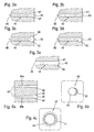
- FIGS. 3a to 3e show detailed views of holes 44 within the workpiece 40 in a cross-sectional view parallel to a bore center axis 46 of the hole 44.
- An unillustrated laser beam 30 was directed from the left parallel to the wellbore center axis 46 on the workpiece 40, piercing the region of its impact the laser beam 30, the workpiece 40, wherein the place of entry into the FIGS. 3a to 3e not shown.
- the respective outlet openings 43 of the holes 44 are in the FIGS. 3a to 3e recognizable.
- a region of the outlet opening 43 of the borehole 44 has a symmetrical expansion 41 or rounding, which by preferably symmetrical arrangement of a backing, not shown.
- the Bohrungsstoffachse 46 within a range behind, in the illustration of FIGS. 3a to 3e right next to, the exit opening 43 was caused.
- the extent of this widening 41 or rounding can be influenced by suitable spacing of the backing relative to the outlet opening 43.
- the widening 41 of a region of the outlet opening 43 of the borehole 44 is asymmetrical or only rounded on one side.
- the method according to the invention was carried out such that the backing was arranged under tilting at a suitable angle to the borehole center axis 46 in a region behind the outlet opening 43.
- Drill hole 44 off Figure 3c see page 12 has symmetrical or bilateral bulges 42 in a region of the outlet opening 43 of the hole 44.
- Such a bulge 42 can be realized, for example, by the described interaction between laser beam and formed plasma.
- Hole 12 shown on page 12 has an asymmetrical bulge 42.
- Such asymmetrical formation of the bulge 42 is facilitated by tilting a nozzle introducing the process gas at a suitable angle relative to the borehole center axis 46 and the laser beam, respectively.
- the borehole 44 is designed such that it has a combination of expansion 41 and bulge 42 in a region of the outlet opening 43.
- Such a design can be achieved by combining the measures described above (tilting of the backing and process gas at an angle).
- FIGS. 4a to 4c Further embodiments of holes 44 produced within a workpiece 40 and produced outlet openings 43 are shown in longitudinal section and in plan view, respectively.
- FIG. 4a see page 12 shows two different shapes of bulges 42 in longitudinal section. Furthermore, by applying the workpiece by a laser beam incident from the left entrance openings 45 are shown, which have a smaller diameter than the outlet openings 43 right.
- the bulge 42 is analogous to 3d figure asymmetric, in the lower hole 44b, however, are analogous to Figure 3c two symmetrical bulges 42 shown.
- outlet opening 43 has an asymmetrical widening 41 or rounding. This was done with appropriate measures, as described with reference to FIG. 3b described, realized. From the same perspective as FIG. 4b shows Figure 4c see page 12 an outlet opening 43 with symmetrical expansion 41 or rounding, which by analogous implementation of the method according to the invention, as with reference to FIG. 3a described, realized.
Description
Die vorliegende Erfindung betrifft ein Verfahren zum Laserbohren nach dem Oberbegriff des Patentanspruchs 1 und eine entsprechende Vorrichtung nach dem Oberbegriff des Patentanspruchs 8 (siche, z.B.,
In Düsen von Kraftstoffeinspritzsystemen werden herkömmlicherweise Präzisionskleinstlöcher mittels Erodierverfahren eingebracht. Mittels dieser Technik können derzeit in Großserien minimale Durchmesser von etwa 120 µm hergestellt werden. Das Laserbohren ermöglicht darüber hinaus auch die Herstellung von Präzisionslöchern mit Durchmessern kleiner als 120 µm, ist aber als Großserienverfahren bisher noch nicht eingeführt.In nozzles of fuel injection systems, precision mini-holes are conventionally introduced by means of erosion processes. By means of this technique, minimum diameters of about 120 μm can currently be produced in large series. In addition, laser drilling enables the production of precision holes with diameters smaller than 120 μm, but has not yet been introduced as a large-scale production process.
Auf dem Gebiet der Kraftstoffeinspritzung werden in zunehmendem Maße konische Löcher dahingehend gefordert, dass eine Kraftstoffaustrittsöffnung einen kleineren Durchmesser besitzt als eine Kraftstoffeintrittsöffnung. Derartige Präzisions-Kleinstlöcher kommen bereits in Systemen für Dieselkraftstoffe (Direkteinspritzung) oder für Benzinkraftstoffe (Saugrohr- und Direkteinspritzung) zur Anwendung.In the field of fuel injection conical holes are increasingly required in that a fuel outlet opening has a smaller diameter than a fuel inlet opening. Such precision micro-holes are already used in systems for diesel fuels (direct injection) or for gasoline fuels (intake manifold and direct injection).
In der
In der
Grundsätzlich ist es beim Laserbohren eines Werkstückes auch bekannt, ein sogenanntes Backing als Rückraumschutzmaterial einzusetzen. So wird beispielsweise in
Die Möglichkeit, ein Werkstück mittels eines plasmaunterstützten Laserverfahrens zu bearbeiten, wird in der
Bei allen bisherigen Bohrprozessen muss die erzeugte Bohrung durch hydroerosives (HE) Runden nachbehandelt werden. Dies dient beispielsweise bei Kraftstoffeinspritzsystemen (neben der Verbesserung der Bohrwandoberfläche und der Verringerung der Streuung zwischen den hydraulischen Durchsätzen der einzelnen Bohrlöcher einer Düse) vor allem der Verrundung der Kante des Kraftstoffeinlaufs. Dies führt zu einer deutlichen Verminderung des Strömungswiderstandes an dieser Stelle und vermindert außerdem unerwünschte Kavitationserscheinungen.In all previous drilling processes, the generated hole must be aftertreated by hydroerosive (HE) rounding become. This is useful, for example, in fuel injection systems (in addition to improving the bore wall surface and reducing the spread between the hydraulic flow rates of the individual wells of a nozzle), especially the rounding of the edge of the fuel inlet. This leads to a significant reduction of the flow resistance at this point and also reduces unwanted cavitation phenomena.
Eine weitere deutliche Verbesserung in dieser Richtung wird durch die Kombination von Konizität und ausgeprägter HE-Verrundung erreicht.A further significant improvement in this direction is achieved by the combination of taper and pronounced HE rounding.
Mit der Erfindung soll während des Bohrprozesses mit Kurzpuls- (ns) oder Ultrakurzpuls- (ps/fs) Lasern gezielt der Verlauf des Austritts der Bohrung (Kraftstoffeinlauf) beeinflusst werden. Insbesondere soll eine einfache und unaufwendige Bereitstellung verschiedener symmetrischer und asymmetrischer Austrittsverläufe, beispielsweise mit Ausweitungen und Ausbauchungen realisiert werden.With the invention, during the drilling process with short-pulse (ns) or ultra-short-pulse (ps / fs) lasers, the course of the exit of the bore (fuel inlet) is to be influenced in a targeted manner. In particular, a simple and inexpensive provision of different symmetrical and asymmetrical exit curves, for example, with extensions and bulges to be realized.
Dieses Ziel wird erreicht mit einem Verfahren zum Laserbohren mit den Merkmalen des Patentanspruchs 1 sowie einer entsprechenden Vorrichtung mit den Merkmalen des Patentanspruchs 8.This object is achieved with a method for laser drilling with the features of patent claim 1 and a corresponding device with the features of patent claim 8.
Bei dem erfindungsgemäß vorgesehenen Verfahren zum Laserbohren wird ein Bereich eines Bauteils mit einem Laserstrahl beaufschlagt, wobei innerhalb dieses Bereiches ein Loch erzeugt wird. Diese Beaufschlagung bzw. Bohrung wird unter einer einstellbaren Prozessgasatmosphäre durchgeführt. Aufgrund einer Wechselwirkung zwischen dem verwendeten Laserstrahl und dem gewählten Prozessgas innerhalb des von dem Laserstrahl beaufschlagten Bereiches bzw. Loches wird dabei durch Ionisierung des Prozessgases Plasma gebildet. Zusätzlich ist erfindungsgemäß vorgesehen, dass an einer durch den Laserstrahl erzeugten Austrittsöffnung des Loches ein verkippbares Backing angeordnet wird.In the method according to the invention for laser drilling, a region of a component is exposed to a laser beam, a hole being produced within this region. This admission or bore is carried out under an adjustable process gas atmosphere. Due to an interaction between the laser beam used and the selected process gas within the area acted upon by the laser beam or hole plasma is formed by ionization of the process gas. In addition, the invention provides that a tiltable backing is arranged on an outlet opening of the hole produced by the laser beam.
Das erfindungsgemäß verwendete Prozessgas bzw. Gasgemisch dient primär der Steigerung der Bearbeitungsqualität sowie einer Optimierung der Bearbeitungszeit, insbesondere einer Verkürzung der Bearbeitungszeit. Hierbei wird durch die Schaffung spezieller Prozessgastmosphären indirekt Einfluss auf die Laserstrahl-Materie-Wechselwirkung im beaufschlagten Bereich bzw. Loch und somit auf den Bearbeitungsprozess genommen. Die Art der Prozessgasatmosphäre bestimmt die Eigenschaften der sich erfindungsgemäß bildenden Plasmen bei der Wechselwirkung mit der eingesetzten Laserstrahlung mit dem zu bearbeitenden Material bzw. Werkstoff, wobei die Plasmabildung durch Materialdampf unterstützt wird. Als Laser kommt beispielsweise ein Festkörperlaser (Nd:YAG) zum Einsatz. Verschiedene Prozessgase erzeugen jeweils Plasmen, die sich z. B. in ihrer Temperatur und Expansion unterscheiden können.The process gas or gas mixture used according to the invention serves primarily to increase the quality of the processing and to optimize the processing time, in particular to shorten the processing time. The creation of special process atmospheres indirectly influences the laser beam-matter interaction in the applied area or hole and thus the processing process. The type of process gas atmosphere determines the properties of the plasmas forming according to the invention in the interaction with the laser radiation used with the material or material to be processed, wherein the plasma formation is supported by material vapor. As a laser, for example, a solid-state laser (Nd: YAG) is used. Different process gases each generate plasmas, which are z. B. can differ in their temperature and expansion.
Als Vorteil des erfindungsgemäßen Verfahrens ist insbesondere zu erwähnen, dass für die Herstellung von Verrundungen die Prozesszeit des HE-Rundens deutlich herabgesetzt werden kann, bzw. dass HE-Runden gar nicht mehr erforderlich ist. Außerdem können durch das erfindungsgemäße Verfahren Kraftstoffeintritte in einer Art gestaltet werden, wie dies das HE-Runden nicht erlaubt. Insbesondere können durch das erfindungsgemäße Verfahren asymmetrische Verrundungen eingebracht werden oder symmetrische respektive asymmetrische Ausbauchungen kurz hinter dem Kraftstoffeintritt erzeugt werden. Verrundungen haben den Vorteil eines verbesserten Einströmverhaltens während Ausbauchungen dazu dienen können, Verwirbelungen, die am Kraftstoffeintritt entstehen können, zu verhindern oder auch gezielt zu erzeugen.As an advantage of the method according to the invention is to mention in particular that for the production of fillets, the process time of HE rounding can be significantly reduced, or that HE rounds is no longer necessary. In addition, by the method according to the invention fuel inlets can be designed in a way that does not allow HE rounding. In particular, asymmetrical fillets can be introduced by the method according to the invention or symmetrical or asymmetrical bulges can be generated shortly after the fuel inlet. Fillets have the advantage of improved inflow behavior while bulges can be used to prevent turbulence, which may occur at the fuel inlet, or to produce targeted.
Bedeutsam für die gezielte Gestaltung des Austritts ist insbesondere der Plasmazustand kurz vor und während des Wiederaustritts des Laserstrahls aus dem Material. Je nach den gewählten Parametern wie Gaszusammensetzung, Gasdruck und/oder Gasströmungsrichtung können sich Verrundungen, Ausbauchungen und/oder scharfe Austrittskanten ausbilden, wobei dies rotationssymmetrisch gleichmäßig über den gesamten Bohrlochaustritt erfolgen kann, oder die Phänomene nur auf einer Seite auftreten können.Significant for the targeted design of the exit is in particular the plasma state shortly before and during the re-emergence of the laser beam from the material. Depending on the selected parameters such as gas composition, gas pressure and / or gas flow direction, fillets, bulges and / or sharp exit edges may form, which may be rotationally symmetric uniform over the entire borehole exit, or the phenomena may occur only on one side.
Rückraumschutzmaterialien, sogenannte Backings haben die Aufgabe, eine freie Propagation des Laserstrahls nach seinem Wiederaustritt aus dem Werkstoff bzw. Material zu verhindern. Dies kann herkömmlicherweise dazu dienen, ein anderes Werkstück bzw. Bauteil oder Bereiche desselben Werkstücks vor Beschädigung zu schützen. Außerdem können derartige Backings den Zustand eines geschlossenen Bohrlochs für eine bestimmte Zeit aufrechterhalten und somit dazu beitragen, dass eine Austrittsöffnung bzw. ein Bohrungsaustritt wie gewünscht entstehen kann.Backspace protection materials, so-called backings have the task of preventing free propagation of the laser beam after its re-emergence from the material or material. This may conventionally serve to protect another workpiece or parts or areas of the same workpiece from damage. In addition, such backings may maintain the condition of a closed well for a certain time and thus help to create an exit orifice as desired.
Backings bestehen je nach Anwendungsfall aus verschiedensten Materialien, wie z. B. Polymeren, Metallen oder keramischen Werkstoffen.Backings exist depending on the application of different materials, such. As polymers, metals or ceramic materials.
Ein Backing kann die Ausbildung eines Bohrlochaustrittes beeinflussen, indem es die ankommende Laserstrahlung zurück in Richtung Werkstoff reflektiert oder indem es das aus dem Prozessgas ionisierte Plasma in seiner Ausbreitung beeinflusst und somit zu einem weiteren Materialabtrag führt. Einen weiteren Einfluss kann ein Plasma haben, das gegebenenfalls durch den Abtrag des Backings entsteht.Backing can influence the formation of a borehole outlet by reflecting the incoming laser radiation back towards the material or by influencing the plasma ionized from the process gas in its propagation, thus leading to further material removal. Another influence can be a plasma, which may be caused by the removal of the backing.
Vorteilhafte Ausgestaltungen des erfindungsgemäßen Verfahrens bzw. der erfindungsgemäßen Vorrichtung sind Gegenstand der Unteransprüche.Advantageous embodiments of the method and the device according to the invention are the subject of the dependent claims.
Bei dem Verfahren wird als Prozessgas zweckmäßigerweise ein inertes Gas, wie Stickstoff, insbesondere unter Zusatz von Edelgasen wie Helium, Argon und dergleichen verwendet. Der Einsatz eines derartigen Prozessgases hat zum Vorteil, dass ein zu beaufschlagender Bereich inert wird, so dass eine Oxidation dieses Bereiches vermieden wird. Außerdem wird durch eine derartige Zusammensetzung des Prozessgases erreicht, dass hinreichende Bohrwandoberflächenqualitäten und Schmelzfilmdicken gewährleistet sind.In the method, an inert gas such as nitrogen is suitably used as the process gas, in particular with the addition of noble gases such as helium, argon and the like. The use of such a process gas has the advantage that a region to be acted becomes inert, so that oxidation of this region is avoided. In addition, by such a composition of the process gas ensures that sufficient bore surface qualities and melt film thicknesses are ensured.
Desweiteren ist bevorzugt vorgesehen, dass das Prozessgas unter Druck gesetzt ist, wobei der Druck bevorzugt unter etwa 1,5 bar eingestellt ist. Hierdurch wird die Entstehung von Ausbauchungen in den hergestellten Löchern begünstigt. Es ist ebenfalls möglich, höhere Drücke zu wählen, wodurch Ausbauchungen unterdrückt werden können. Allgemein ist festzustellen, dass die erfindungsgemäß verwendeten Drücke zu Ausbauchomen in der Nähe des Randbereiches des zu bearbeitenden Werkstücks führen. Je höher der verwendete Druck, desto tiefer verlagert sich eine Ausbauchom in das Innere des Werkstücks.Furthermore, it is preferably provided that the process gas is pressurized, wherein the pressure is preferably set below about 1.5 bar. This promotes the formation of bulges in the holes produced. It is also possible to choose higher pressures, which can suppress bulges. In general, it can be stated that the pressures used according to the invention lead to bulging phenomena in the vicinity of the edge region of the workpiece to be machined. The higher the pressure used, the deeper a Ausbauchom moves into the interior of the workpiece.
Desweiteren kann bevorzugt vorgesehen sein, die Beaufschlagungsrichtung des Prozessgases durch Verkippung relativ zur Richtung des Laserstrahles einzustellen. Der Winkel der Verkippung kann hierbei insbesondere zwischen 0° und 15° liegen. Durch geeignete Wahl eines Verkippungswinkels wird gewährleistet, dass Lochformen, insbesondere Ausbauchungen oder Aufweitungen, verschieden stark asymmetrisch ausgebildet werden können.Furthermore, it can preferably be provided to adjust the loading direction of the process gas by tilting relative to the direction of the laser beam. The angle of tilting can in this case in particular be between 0 ° and 15 °. By a suitable choice of a tilt angle ensures that hole shapes, in particular bulges or widening, can be designed differently strong asymmetric.
Durch die bei der Durchführung des erfindungsgemäßen Verfahrens gebildeten Plasmen können errechnete Drücke in der Größenordnung einiger 100 bar und Strömungsgeschwindigkeiten von mehreren 10 km/s in dem beaufschlagten Bereich bzw. Loch entstehen. Dies hat vorteilhafterweise zur Folge, dass unter anderem durch ein beschleunigtes Ausbringen einer dadurch entstehenden Schmelze zu einem höheren Materialabtrag aktiv beigetragen wird.By the plasmas formed when carrying out the method according to the invention, calculated pressures of the order of magnitude of a few 100 bar and flow velocities of several 10 km / s can arise in the area or hole acted upon. This advantageously has the consequence that, inter alia, an accelerated discharge of a melt resulting thereby actively contributes to higher material removal.
Die Ionisation des Prozessgases kann, außer von den herrschenden Einbringungsbedingungen des Prozessgases (Zusammensetzung, Druck, Richtung), insbesondere auch durch Eigenschaften des Laserstrahls wie Wellenlänge und Leistung beeinflusst sein.The ionization of the process gas can, apart from the prevailing conditions of introduction of the process gas (composition, pressure, direction), in particular be influenced by properties of the laser beam such as wavelength and power.
Ein hierbei zum Einsatz kommendes Backing kann thermische bzw. optische Eigenschaften aufweisen, die die Form bzw. Ausgestaltung der Austrittsöffnung beeinflussen. Insbesondere ist hierbei vorgesehen, geeignete metallische Werkstoffe, insbesondere Kupfer, vorzusehen. Diese Materialeigenschaften sind insbesondere für das Maß der Aufweitung der Austrittsöffnung von Bedeutung. So entstehen beispielsweise bei Laserwellenlängen von 1064 µm und einem in geeignetem Abstand zur Austrittsöffnung angeordneten Backing aus Kupfer relativ große, hingegen bei einem Backing aus Stahl relativ kleine Aufweitungen. Desweiteren kann die Geometrie des Backings die Form bzw. Ausgestaltung der Austrittsöffnung beeinflussen. Erfindungsgemäß wird insbesondere die Verwendung von Kupfer als Backingmaterial bevorzugt. Es sei darauf hingewiesen, dass Kupfer in der Regel im Bereich des Motorenbaus ungern verwendet wird, da es im Falle von Kupferablagerungen im Motorbereich aufgrund von Wechselwirkungen mit im verwendeten Kraftstoff vorhandenen Schwefel zur Sulfidbildung kommen kann, wodurch die Langlebigkeit des Motors negativ beeinflusst wird. Die im Rahmen der vorliegenden Erfindung ausnutzbaren Eigenschaften des Kupfers im Zusammenhang mit der Erzeugung von speziell ausgebildeten Löchern in Werkstücken überwiegen diese Nachteile jedoch deutlich.A backing used in this case can have thermal or optical properties which influence the shape or design of the outlet opening. In particular, it is provided here to provide suitable metallic materials, in particular copper. These material properties are particularly important for the degree of expansion of the outlet opening of importance. For example, at laser wavelengths of 1064 .mu.m and a backing made of copper arranged at a suitable distance from the outlet opening, relatively large expansions are formed, whereas in the case of a backing made of steel relatively small widenings occur. Furthermore, the geometry of the backing can influence the shape or design of the outlet opening. According to the invention, the use of copper as backing material is particularly preferred. It should be noted that copper is generally reluctant to be used in the field of engine construction because, in the case of copper deposits in the engine area, sulfide formation may occur due to interactions with sulfur present in the fuel being used, thereby adversely affecting the longevity of the engine. However, the exploitable in the context of the present invention properties of copper in connection with the production of specially formed holes in workpieces outweigh these disadvantages clearly.
Desweiteren kann bevorzugt vorgesehen sein, das Backing in einem die Form der Austrittsöffnung beeinflussenden Abstand zur Austrittsöffnung anzuordnen. Ein solcher Abstand wird bevorzugt zwischen 20 µm bis 200 µm gewählt.Furthermore, it can preferably be provided, the backing in an influencing the shape of the outlet opening distance to arrange the outlet opening. Such a distance is preferably selected between 20 μm to 200 μm.
Durch eine geeignete Wahl eines solchen Abstandes lässt sich die Geometrie der Aufweitung des Bohrlochaustritts in einfacher Weise beeinflussen.By a suitable choice of such a distance, the geometry of the expansion of the borehole outlet can be influenced in a simple manner.
Das Backing ist, gemäß der Erfindung, durch Verkippung relativ zur Austrittsöffnung unter einem vorgegebenen Winkel angeordnet. Unterschiedlich stark gewählte Verkippungen erzeugen hierbei unterschiedlich stark asymmetrische Aufweitungen der Austrittsöffnung des Bohrlochs. Hierbei bevorzugt zur Anwendung kommende Winkel bewegen sich zwischen 0° und 20°.The backing is, according to the invention, arranged by tilting relative to the outlet opening at a predetermined angle. Differently strongly selected tiltings in this case produce differently asymmetrical widening of the outlet opening of the borehole. Preferred angles used here are between 0 ° and 20 °.
Durch eine geeignete Anordnung des Backings relativ zur Austrittsöffnung werden in einem Bereich der Austrittsöffnung eines Loches in einfacher Weise asymmetrische Verrundungen eingebracht, was zum Vorteil hat, dass ein nachträgliches HE-Runden gar nicht mehr oder nur in begrenztem Umfang erforderlich ist.By a suitable arrangement of the backing relative to the outlet opening asymmetric rounding be introduced in a region of the outlet opening of a hole in a simple manner, which has the advantage that a subsequent HE rounding is no longer required or only to a limited extent.
Die erfindungsgemäße Vorrichtung, mit welcher insbesondere das erfindungsgemäße Verfahren durchführbar ist, zeichnet sich dadurch aus, dass sie einen Laserstrahl, eine Haltevorrichtung für ein zu bearbeitendes Bauteil und Mittel zur Einstellung einer Prozessgasatmosphäre aufweist.The device according to the invention, with which in particular the method according to the invention can be carried out, is characterized in that it comprises a laser beam, a holding device for a component to be processed and means for adjusting a process gas atmosphere.
Als Mittel zur Einstellung der Prozessgasatmosphäre kann bevorzugt wenigstens eine Gasdüse vorgesehen sein. Hiermit ist strömendes Prozessgas geeigneter Zusammensetzung in einfach zu steuernder bzw. regelnder Weise unter geeignetem Druck sowie einem geeigneten Winkel auf den zu beaufschlagenden Bereich eines Werkstücks richtbar. Eine geeignete Zusammensetzung des Prozessgases kann durch einen Gasmischer bereitgestellt werden.As means for adjusting the process gas atmosphere may preferably be provided at least one gas nozzle. This allows flowing process gas of suitable composition to be controlled in a manner which is easy to control under suitable pressure and at a suitable angle directing area of a workpiece directable. A suitable composition of the process gas may be provided by a gas mixer.
Gemäß der Erfindung, ist an einer am Bauteil durch Einwirkung des Laserstrahls erzeugten Austrittsöffnung ein Backing positioniert.According to the invention, a backing is positioned on an outlet opening produced on the component by the action of the laser beam.
Die vorliegende Erfindung wird nun anhand der beigefügten Zeichnung weiter erläutert. In dieser zeigt bzw. zeigen
-
Figur 1 eine schematische Darstellung einer bevorzugten Ausführungsform der erfindungsgemäßen Vorrichtung zur Durchführung des erfindungsgemäßen Laserbohrverfahrens, -
Figur 2 ein Detail der Vorrichtung gemäßFigur 1 in vergrößerter Darstellung, -
Figur 3a bis Figur 3e schematische Darstellungen von erfindungsgemäß und nicht erfindungsgemäß hergestellten Bohrlöchern in seitlicher Schnittansicht, und -
Figuren 4a bis 4c schematische Darstellungen von erfindungsgemäß hergestellten und nicht erfindungsgemäß Bohrlöchern in seitlicher Schnittansicht bzw. in Draufsicht auf der Grundlage elektronenmikroskopischer Aufnahmen.
-
FIG. 1 a schematic representation of a preferred embodiment of the device according to the invention for carrying out the laser drilling method according to the invention, -
FIG. 2 a detail of the device according toFIG. 1 in an enlarged view, -
Figure 3a to Figure 3e schematic representations of inventively and not inventively produced boreholes in a side sectional view, and -
FIGS. 4a to 4c schematic representations of inventively prepared and not according to the invention boreholes in lateral sectional view or in plan view on the basis of electron micrographs.
In
Das zur Durchführung des erfindungsgemäßen Verfahrens benötigte Prozessgas wird durch einen Gasmischer 11 bereitgestellt und über eine Leitung 11a auf eine Gasdüse 12 gegeben. Das Prozessgas wird mit Hilfe der Gasdüse 12 unmittelbar auf das Werkstück 40 geblasen.The process gas required for carrying out the method according to the invention is provided by a
Das Werkstück 40 ist in einer Handhabung 50 befestigt. Diese Handhabung 50 kann durch geeignete Maßnahmen in alle drei Raumrichtungen x, y bzw. z bewegt werden, so dass eine für die Durchführung des Verfahrens geeignete Positionierung des Werkstückes 40 einstellbar ist. Durch Positionierung der Fokussierlinse 36 entlang der Achse z kann der Laserstrahl 30 in seiner Fokuslage variiert werden. Ebenso lässt sich die Gasdüse 12 relativ zu der Richtung des durch die Gasdüse 12 gehenden Strahlenganges des Laserstrahls 30 bzw. zum Werkstück 40 positionieren. Dabei erfolgt eine Bewegung entlang der Richtung x bzw. y. Auch eine Verdrehung der Gasdüse 12 ist mittels eines geeigneten Mechanismus realisierbar, wobei eine derartige Verschwenkbarkeit in
Mit dieser Ausführungsform der erfindungsgemäßen Vorrichtung 100 ist das erfindungsgemäße Verfahren zum Laserbohren in einfacher Weise realisierbar. Innerhalb eines zu beaufschlagenden Bereiches trifft der Laserstrahl 30, nachdem sein Strahlengang die Gasdüse 12 durchquert hat, auf das Werkstück 40. Ein gewähltes bzw. eingestelltes Prozessgas strömt, mittels des Gasmischers 11 bereitgestellt, aus einer einstellbaren Richtung, unter Druck aus der Düse 12 auf den zu beaufschlagenden Bereich des Werkstücks 40. Insbesondere wird hiermit die Ionisation von Prozessgas zu Plasma durch Wechselwirkung zwischen Prozessgas und Laserstrahl 30 innerhalb des Beaufschlagungsbereiches begünstigt.With this embodiment of the
In
Ein mittels des Laserbohrverfahrens in dem Werkstück 40 zu erzeugendes Loch 44 entsteht an der Stelle des Werkstückes 40, an der der Laserstrahl 30 auf dem Werkstück 40 auftrifft bzw. dieses beaufschlagt, wobei der Laserstrahl an einer Austrittsöffnung 43 des Loches 44 an der dem Backing 20 zugewandeten Seite des Werkstücks 40 austritt. Das in einem geeigneten Winkel aus einem geeigneten Abstand aus einer nicht dargestellten Gasdüse auf das Werkstück 40 geblasene Prozessgas wird durch Wechselwirkung mit dem Laserstrahl 30 im Bereich des Lochs 44 bzw. einem Bereich der Austrittsöffnung 43 durch Wechselwirkung zu Plasma ionisiert.A
Hierdurch entstehen gezielt geometrische Ausgestaltungen im Bereich des Loches 44 bzw. der Austrittsöffnung 43, wie nun anhand nachfolgender Figuren beispielhaft dargestellt wird.This results in targeted geometrical configurations in the region of the
Die
In
In
Bohrloch 44 aus
Das in
In
In den
Die in
Claims (9)
- Method for laser drilling, in which a region of a workpiece (40) is exposed to a laser beam (30), so that a hole (44) is produced in this region, characterized in that- the method is carried out in an adjustable process gas atmosphere in such a way that, as a result of an interaction between the laser beam and the process gas, plasma is formed in the region or hole (44) that is exposed to the laser beam (30),- a backing (20) is arranged at an outlet opening (43) of the hole (44) that is produced by the laser beam (40), and- the backing (20) is arranged such that it is tilted in relation to the outlet opening and/or the workpiece (40) at a specific angle, influencing the form of the outlet opening (43).
- Method according to Claim 1, characterized in that an inert gas, in particular nitrogen, in particular with the addition of noble gases such as helium, argon and the like, is used as the process gas.
- Method according to either of Claims 1 and 2, characterized in that the process gas is subjected to pressure, the process gas being subjected in particular to a pressure of at most 1.5 bar.
- Method according to one of Claims 1 to 3, characterized in that the direction of exposure of the process gas is adjusted by tilting in relation to the direction of the laser beam (30), the angle of the tilting being in particular up to 15°.
- Method according to one of Claims 1 to 4, characterized in that a material used for the backing (20) is selected with thermal and/or optical properties (4) that influence the form of the outlet opening (43), in particular a metallic material, in particular a copper-containing material.
- Method according to one of Claims 1 to 5, characterized in that the backing (20) is arranged at a distance from the outlet opening (43) and/or the workpiece (40) that influences the form of the outlet opening (43), the distance preferably being between 20 µm and 200 µm.
- Method according to one of Claims 1 to 6, characterized in that the angle of the tilting of the backing (20) is up to 20°.
- Device for laser drilling, with a laser (31), which exposes a region of a workpiece (40) to a laser beam (30) to produce a hole (44), characterized in that the device has the following features:- means (11, 12) for adjusting a process gas atmosphere in the region and/or hole (44) that is exposed to the laser beam (30) in such a way that, as a result of an interaction between the laser beam (30) and the process gas, there is a formation of plasma in the region or hole (44) that is exposed to the laser beam,- a backing (20), which can be positioned at an outlet opening (43) of a produced hole (44) and can be tilted in relation to the outlet opening (43) and/or the workpiece (40), is provided for forming the outlet opening (43),- wherein a mount (51) for the relative positioning of the workpiece in relation to a handling fixture (50), and a further mount (52) for the relative positioning of the backing (20) in relation to the handling fixture (50) and a controller are provided, so that, by controlling the mounts (51, 52), the backing (20) and the workpiece (40) can be spatially positioned in relation to each other in a desired way before or during the laser drilling of the workpiece (40).
- Device according to Claim 8, characterized in that the means (11, 12) for adjusting a process gas atmosphere have at least one gas nozzle (12).
Applications Claiming Priority (3)
| Application Number | Priority Date | Filing Date | Title |
|---|---|---|---|
| DE10300134A DE10300134A1 (en) | 2003-01-07 | 2003-01-07 | Method and device for laser drilling |
| DE10300134 | 2003-01-07 | ||
| PCT/DE2003/003801 WO2004060603A1 (en) | 2003-01-07 | 2003-11-17 | Method and device for laser drilling in a process gas atmosphere |
Publications (2)
| Publication Number | Publication Date |
|---|---|
| EP1583633A1 EP1583633A1 (en) | 2005-10-12 |
| EP1583633B1 true EP1583633B1 (en) | 2008-02-27 |
Family
ID=32519628
Family Applications (1)
| Application Number | Title | Priority Date | Filing Date |
|---|---|---|---|
| EP03779697A Expired - Lifetime EP1583633B1 (en) | 2003-01-07 | 2003-11-17 | Method and device for laser drilling in a process gas atmosphere |
Country Status (5)
| Country | Link |
|---|---|
| US (1) | US7301121B2 (en) |
| EP (1) | EP1583633B1 (en) |
| JP (1) | JP4741243B2 (en) |
| DE (2) | DE10300134A1 (en) |
| WO (1) | WO2004060603A1 (en) |
Families Citing this family (14)
| Publication number | Priority date | Publication date | Assignee | Title |
|---|---|---|---|---|
| DE502004003169D1 (en) * | 2004-11-30 | 2007-04-19 | Delphi Tech Inc | Device for producing a bore by means of laser radiation |
| DE102005042270B4 (en) * | 2005-09-06 | 2015-11-19 | MTU Aero Engines AG | Method for producing bores and manufacturing arrangement therefor |
| US7719676B2 (en) * | 2007-02-15 | 2010-05-18 | Baker Hughes Incorporated | Downhole laser measurement system and method of use therefor |
| JP5249520B2 (en) * | 2007-03-28 | 2013-07-31 | 本田技研工業株式会社 | Laser nozzle processing apparatus and laser processing method |
| US20090057282A1 (en) * | 2007-08-15 | 2009-03-05 | Chunfu Huang | Laser machining method utilizing variable inclination angle |
| US8242408B2 (en) * | 2007-08-15 | 2012-08-14 | Caterpillar Inc. | Masking device for laser machining system and method |
| DE102009015401A1 (en) * | 2009-03-27 | 2010-09-30 | Mtu Aero Engines Gmbh | Covering device for a workpiece to be machined by means of a laser |
| US8664563B2 (en) * | 2011-01-11 | 2014-03-04 | Gas Technology Institute | Purging and debris removal from holes |
| DE102011079815A1 (en) * | 2011-07-26 | 2013-01-31 | Robert Bosch Gmbh | Protective device for laser processing of holes in components |
| DE102012110971A1 (en) * | 2012-11-14 | 2014-05-15 | Schott Ag | Separating transparent workpieces |
| JP6365365B2 (en) * | 2015-03-17 | 2018-08-01 | 株式会社デンソー | Laser processing equipment |
| CN107671435A (en) | 2017-11-08 | 2018-02-09 | 钦成科技有限公司 | Rear wall protection device and its application method for atomizer punching |
| DE102020201530A1 (en) * | 2020-02-07 | 2021-08-12 | Robert Bosch Gesellschaft mit beschränkter Haftung | Laser drilling or laser cutting with improved back space protection |
| DE102021202671A1 (en) | 2021-03-18 | 2022-09-22 | Vitesco Technologies GmbH | Mixing tube blank, mixing tube, mixing tube holder, ejector pump and method for their manufacture |
Family Cites Families (23)
| Publication number | Priority date | Publication date | Assignee | Title |
|---|---|---|---|---|
| DE2740755A1 (en) * | 1976-10-07 | 1978-04-13 | Lasag Ag | METHOD OF REMOVING MATERIAL FROM A METALLIC WORKPIECE, IN PARTICULAR FOR DRILLING, USING A FOCUSED LASER BEAM IMPULSE |
| CH605010A5 (en) * | 1976-10-07 | 1978-09-29 | Lasag Sa | |
| EP0299143A1 (en) | 1987-06-12 | 1989-01-18 | Raycon Textron Inc. | Laser/EDM drilling manufacturing cell |
| FR2699844B1 (en) * | 1992-12-30 | 1995-02-03 | Snecma | Method and device for laser beam machining. |
| JP3526964B2 (en) * | 1995-05-29 | 2004-05-17 | 株式会社アマダ | Laser welding method for high reflectivity materials |
| US5744780A (en) * | 1995-09-05 | 1998-04-28 | The United States Of America As Represented By The United States Department Of Energy | Apparatus for precision micromachining with lasers |
| JPH09136183A (en) * | 1995-11-10 | 1997-05-27 | Matsushita Electric Ind Co Ltd | Laser beam machine and its processing torch |
| JPH09168877A (en) * | 1995-12-21 | 1997-06-30 | Mitsubishi Electric Corp | Method and device for machining wiring board |
| JP3694979B2 (en) * | 1996-06-05 | 2005-09-14 | Jfeスチール株式会社 | Laser welding method |
| JPH10277747A (en) * | 1997-04-08 | 1998-10-20 | Toshiba Corp | Method and device for working object to be worked |
| JP3707914B2 (en) * | 1997-09-25 | 2005-10-19 | 株式会社東芝 | Drilling method and protective material |
| JP3401425B2 (en) * | 1998-01-21 | 2003-04-28 | 理化学研究所 | Laser processing method and laser processing apparatus |
| JPH11284312A (en) * | 1998-03-30 | 1999-10-15 | Ibiden Co Ltd | Method and device for boring via hole |
| JPH11320171A (en) * | 1998-05-13 | 1999-11-24 | Matsushita Electric Ind Co Ltd | Method and device for boring by laser irradiation |
| US6070813A (en) * | 1998-08-11 | 2000-06-06 | Caterpillar Inc. | Laser drilled nozzle in a tip of a fuel injector |
| DE19905571C1 (en) | 1999-02-11 | 2000-11-16 | Bosch Gmbh Robert | Process for creating conical holes using a laser beam |
| DE19908630A1 (en) | 1999-02-27 | 2000-08-31 | Bosch Gmbh Robert | Shielding against laser beams |
| JP2001018082A (en) * | 1999-07-05 | 2001-01-23 | Amada Co Ltd | Laser beam machining method |
| DE19960797C1 (en) * | 1999-12-16 | 2001-09-13 | Mtu Aero Engines Gmbh | Method for producing an opening in a metallic component |
| JP2002001569A (en) * | 2000-06-15 | 2002-01-08 | Kawasaki Heavy Ind Ltd | Laser beam machining device |
| JP2002050849A (en) * | 2000-08-07 | 2002-02-15 | Matsushita Electric Ind Co Ltd | Method and device for laser beam machining |
| DE10054853A1 (en) | 2000-11-06 | 2002-08-01 | Bosch Gmbh Robert | Making cleanly-cut fuel injector micro-perforation by circumscribing with laser focus, employs nanosecond-pulsed laser beam |
| DE10138866B4 (en) * | 2001-08-08 | 2007-05-16 | Bosch Gmbh Robert | Method for drilling a hole in a workpiece by means of a laser beam |
-
2003
- 2003-01-07 DE DE10300134A patent/DE10300134A1/en not_active Withdrawn
- 2003-11-17 JP JP2004564154A patent/JP4741243B2/en not_active Expired - Fee Related
- 2003-11-17 US US10/532,851 patent/US7301121B2/en not_active Expired - Lifetime
- 2003-11-17 WO PCT/DE2003/003801 patent/WO2004060603A1/en active IP Right Grant
- 2003-11-17 EP EP03779697A patent/EP1583633B1/en not_active Expired - Lifetime
- 2003-11-17 DE DE50309281T patent/DE50309281D1/en not_active Expired - Lifetime
Also Published As
| Publication number | Publication date |
|---|---|
| JP2006513036A (en) | 2006-04-20 |
| JP4741243B2 (en) | 2011-08-03 |
| DE50309281D1 (en) | 2008-04-10 |
| DE10300134A1 (en) | 2004-07-15 |
| EP1583633A1 (en) | 2005-10-12 |
| WO2004060603A1 (en) | 2004-07-22 |
| US7301121B2 (en) | 2007-11-27 |
| US20060086700A1 (en) | 2006-04-27 |
Similar Documents
| Publication | Publication Date | Title |
|---|---|---|
| EP1417072B1 (en) | Method and device for drilling holes in workpieces by means of laser beams | |
| EP1583633B1 (en) | Method and device for laser drilling in a process gas atmosphere | |
| EP2207641B1 (en) | Method for boring bottle-like holes having a defined geometry by means of pulsed laser radiation | |
| EP3150328B1 (en) | Method of and processing machine for perforating, drilling or cutting of metallic sheets, with direction a secondary gas beam when a spontaneous ablation occurs | |
| DE102005027800A1 (en) | Device for multiple separation of a flat workpiece from a brittle material by means of laser | |
| DE3822097C2 (en) | ||
| DE3934587A1 (en) | METHOD FOR PRODUCING HIGH-PRECISION THROUGH HOLES IN WORKPIECES BY LASER RADIATION | |
| DE3933448A1 (en) | METHOD AND DEVICE FOR DRILLING A SPECIFICALLY SHAPED BORE IN A WORKPIECE | |
| DE102011000005A1 (en) | Apparatus and method for processing a workpiece with a laser beam | |
| EP4017674B1 (en) | Method for flame cutting by means of a laser beam | |
| DE60122634T2 (en) | One using a high density energy beam machining method and apparatus for this method | |
| DE102014203576A1 (en) | Laser processing head with a crossjet nozzle close to the workpiece | |
| EP2106305B1 (en) | Device for flame straightening | |
| DE10340931A1 (en) | Method and device for drilling the finest holes | |
| DE10321123A1 (en) | Device and working method for laser processing | |
| DE102014206358A1 (en) | Method and laser cutting machine for laser cutting small openings | |
| DE102007032231A1 (en) | Laser micro-machining system hole cutter has beam source and an optical unit that sets up rotation and oscillation | |
| DE10226359A1 (en) | Laser processing head, especially for cutting workpiece using laser beam, has device near outlet opening between housing and laser nozzle for producing gas flow transverse to laser beam | |
| DE102013210845A1 (en) | Method for piercing into metallic workpieces by means of a laser beam | |
| WO2020253930A1 (en) | Method and device for drilling components | |
| DE102010010337A1 (en) | Marking device for eyeglass lenses made of plastic, comprises a laser with an exit lens present inside an optical axis for the laser beam to be delivered, and a deflector provided in a beam path after the exit lens | |
| DE10140533A1 (en) | Method and device for micromachining a workpiece with laser radiation | |
| WO2010121767A1 (en) | Nozzle having at least one spray hole for vaporizing fluids | |
| DE10256262B4 (en) | Method for process control in the laser processing of components, apparatus for laser processing and computer program and computer program product for carrying out the method | |
| EP4217141A1 (en) | Method for laser cutting |
Legal Events
| Date | Code | Title | Description |
|---|---|---|---|
| PUAI | Public reference made under article 153(3) epc to a published international application that has entered the european phase |
Free format text: ORIGINAL CODE: 0009012 |
|
| 17P | Request for examination filed |
Effective date: 20050808 |
|
| AK | Designated contracting states |
Kind code of ref document: A1 Designated state(s): AT BE BG CH CY CZ DE DK EE ES FI FR GB GR HU IE IT LI LU MC NL PT RO SE SI SK TR |
|
| RBV | Designated contracting states (corrected) |
Designated state(s): AT BE BG CH CY CZ DE DK EE ES FI FR GB GR HU IE IT LI LU MC NL PT RO SE SI SK TR |
|
| RBV | Designated contracting states (corrected) |
Designated state(s): DE FR GB IT |
|
| 17Q | First examination report despatched |
Effective date: 20051212 |
|
| GRAP | Despatch of communication of intention to grant a patent |
Free format text: ORIGINAL CODE: EPIDOSNIGR1 |
|
| GRAS | Grant fee paid |
Free format text: ORIGINAL CODE: EPIDOSNIGR3 |
|
| GRAA | (expected) grant |
Free format text: ORIGINAL CODE: 0009210 |
|
| AK | Designated contracting states |
Kind code of ref document: B1 Designated state(s): DE FR GB IT |
|
| REG | Reference to a national code |
Ref country code: GB Ref legal event code: FG4D Free format text: NOT ENGLISH |
|
| REF | Corresponds to: |
Ref document number: 50309281 Country of ref document: DE Date of ref document: 20080410 Kind code of ref document: P |
|
| ET | Fr: translation filed | ||
| PLBE | No opposition filed within time limit |
Free format text: ORIGINAL CODE: 0009261 |
|
| STAA | Information on the status of an ep patent application or granted ep patent |
Free format text: STATUS: NO OPPOSITION FILED WITHIN TIME LIMIT |
|
| 26N | No opposition filed |
Effective date: 20081128 |
|
| PGFP | Annual fee paid to national office [announced via postgrant information from national office to epo] |
Ref country code: GB Payment date: 20131122 Year of fee payment: 11 |
|
| PGFP | Annual fee paid to national office [announced via postgrant information from national office to epo] |
Ref country code: IT Payment date: 20131125 Year of fee payment: 11 |
|
| GBPC | Gb: european patent ceased through non-payment of renewal fee |
Effective date: 20141117 |
|
| PG25 | Lapsed in a contracting state [announced via postgrant information from national office to epo] |
Ref country code: GB Free format text: LAPSE BECAUSE OF NON-PAYMENT OF DUE FEES Effective date: 20141117 |
|
| REG | Reference to a national code |
Ref country code: FR Ref legal event code: PLFP Year of fee payment: 13 |
|
| PG25 | Lapsed in a contracting state [announced via postgrant information from national office to epo] |
Ref country code: IT Free format text: LAPSE BECAUSE OF NON-PAYMENT OF DUE FEES Effective date: 20141117 |
|
| PGFP | Annual fee paid to national office [announced via postgrant information from national office to epo] |
Ref country code: FR Payment date: 20151124 Year of fee payment: 13 |
|
| REG | Reference to a national code |
Ref country code: FR Ref legal event code: ST Effective date: 20170731 |
|
| PG25 | Lapsed in a contracting state [announced via postgrant information from national office to epo] |
Ref country code: FR Free format text: LAPSE BECAUSE OF NON-PAYMENT OF DUE FEES Effective date: 20161130 |
|
| PGFP | Annual fee paid to national office [announced via postgrant information from national office to epo] |
Ref country code: DE Payment date: 20200124 Year of fee payment: 17 |
|
| REG | Reference to a national code |
Ref country code: DE Ref legal event code: R119 Ref document number: 50309281 Country of ref document: DE |
|
| PG25 | Lapsed in a contracting state [announced via postgrant information from national office to epo] |
Ref country code: DE Free format text: LAPSE BECAUSE OF NON-PAYMENT OF DUE FEES Effective date: 20210601 |