EP1582955A2 - Robot teaching apparatus - Google Patents
Robot teaching apparatus Download PDFInfo
- Publication number
- EP1582955A2 EP1582955A2 EP05006910A EP05006910A EP1582955A2 EP 1582955 A2 EP1582955 A2 EP 1582955A2 EP 05006910 A EP05006910 A EP 05006910A EP 05006910 A EP05006910 A EP 05006910A EP 1582955 A2 EP1582955 A2 EP 1582955A2
- Authority
- EP
- European Patent Office
- Prior art keywords
- robot
- teaching
- copying control
- external force
- copying
- Prior art date
- Legal status (The legal status is an assumption and is not a legal conclusion. Google has not performed a legal analysis and makes no representation as to the accuracy of the status listed.)
- Withdrawn
Links
Images

Classifications
-
- G—PHYSICS
- G05—CONTROLLING; REGULATING
- G05B—CONTROL OR REGULATING SYSTEMS IN GENERAL; FUNCTIONAL ELEMENTS OF SUCH SYSTEMS; MONITORING OR TESTING ARRANGEMENTS FOR SUCH SYSTEMS OR ELEMENTS
- G05B19/00—Program-control systems
- G05B19/02—Program-control systems electric
- G05B19/42—Recording and playback systems, i.e. in which the program is recorded from a cycle of operations, e.g. the cycle of operations being manually controlled, after which this record is played back on the same machine
- G05B19/423—Teaching successive positions by walk-through, i.e. the tool head or end effector being grasped and guided directly, with or without servo-assistance, to follow a path
-
- G—PHYSICS
- G05—CONTROLLING; REGULATING
- G05B—CONTROL OR REGULATING SYSTEMS IN GENERAL; FUNCTIONAL ELEMENTS OF SUCH SYSTEMS; MONITORING OR TESTING ARRANGEMENTS FOR SUCH SYSTEMS OR ELEMENTS
- G05B19/00—Program-control systems
- G05B19/02—Program-control systems electric
- G05B19/18—Numerical control [NC], i.e. automatically operating machines, in particular machine tools, e.g. in a manufacturing environment, so as to execute positioning, movement or co-ordinated operations by means of program data in numerical form
- G05B19/19—Numerical control [NC], i.e. automatically operating machines, in particular machine tools, e.g. in a manufacturing environment, so as to execute positioning, movement or co-ordinated operations by means of program data in numerical form characterised by positioning or contouring control systems, e.g. to control position from one programmed point to another or to control movement along a programmed continuous path
-
- G—PHYSICS
- G05—CONTROLLING; REGULATING
- G05B—CONTROL OR REGULATING SYSTEMS IN GENERAL; FUNCTIONAL ELEMENTS OF SUCH SYSTEMS; MONITORING OR TESTING ARRANGEMENTS FOR SUCH SYSTEMS OR ELEMENTS
- G05B2219/00—Program-control systems
- G05B2219/30—Nc systems
- G05B2219/39—Robotics, robotics to robotics hand
- G05B2219/39298—Trajectory learning
Definitions
- the present invention relates to a robot teaching apparatus for teaching an operation to an industrial robot, and, more particularly, to for example a robot teaching apparatus suitable for teaching an operation to a robot used in an application for taking a shaped article out of a mold.
- One of the typical techniques for teaching a position and an orientation to a robot is the method of operating the robot by manual operation to make the robot take a desired position and orientation and thereby teaching the position and orientation at that time to the robot (teaching playback method).
- the conventionally most generally used method for manually operating a robot in this way is to operate operation keys (jog movement keys) provided in a teaching operation panel connected to a robot control unit.
- an object of the present invention is to solve the above-mentioned defects of the related art and provide a robot teaching apparatus provided with a simple means enabling an operator to manually operate a robot to teach a position and orientation to the robot which enables the operator to teach the robot by making it move by manual operation by an easily understandable manner and which reliably prevents the robot from colliding with a nearby object or the operator at the time of movement of the robot by the manual operation.
- the present invention introduces to movement of a robot by manual operation a robot control technique enabling an operator to easily obtain an intuitive grasp of the direction of movement of the robot by "movement by copying control", that is, by “moving the robot in accordance with external force applied to the robot", and thereby enables learning of the precise robot operation in a short time and, at the same time, limits the region in which the robot can be moved by such copying control to thereby make it possible to easily avoid interference with a nearby object or the operator. Furthermore, it enables movement by copying control to be allowed in only a predetermined direction so as to more reliably prevent mistaken operation. Note that the reason for the usage of copying control is that movement of a robot by just the small external force given by an operator is difficult.
- the present invention is applied to a robot teaching apparatus for making a robot move according to an external force so as to obtain a desired position and orientation and teaching the position and orientation of the robot after the movement.
- copying control in the present application means control of the operation of a robot by using external force given by an operator etc. as input in place of operation along contours of a master workpiece in general copying control.
- position and orientation of the robot means the position and orientation of a point representing the position and orientation of the robot and typically can be made the position and orientation of the front end point of a tool (tool coordinate system), but may be the position and orientation of a mechanical interface (mechanical interface coordinate system) affixed to the front end of an arm as well.
- a robot teaching apparatus for moving a robot so as to obtain desired position and orientation and teaching the position and orientation of the robot after the movement, which includes a copying control means for detecting or estimating an external force applied to the robot and moving the robot based on the detected or estimated external force; an enabling region setting means for setting an enabling region in which movement of the robot by the copying control means is enabled; and a means for enabling the copying control by the copying control means when the robot is located in the set enabling region.
- the robot teaching apparatus further includes a copying control setting means for setting a restriction that the copying control be carried out in the enabling region for only one or both of movement in a predetermined direction and a change in orientation around a predetermined axis, and the copying control means executes the copying control according to the set restriction.
- a copying control setting means for setting a restriction that the copying control be carried out in the enabling region for only one or both of movement in a predetermined direction and a change in orientation around a predetermined axis, and the copying control means executes the copying control according to the set restriction.
- the enabling region setting means sets the enabling region based on positions of teaching points defined in a previously prepared model teaching program or positions of previously designated teaching points and an index representing the size of the region.
- the copying control means executes the copying control only in a direction of a line segment connecting adjoining teaching points defined in the model teaching program when a control point of the robot is located at any teaching point defined in the model teaching program or on the line segment connecting adjoining teaching points, so that the copying control means guides the movement of the robot between adjoining teaching points along the line segment.
- the robot teaching apparatus further includes a means for making the operator recognize that the robot has approached one of the teaching points by once stopping the copying control when the robot approaches within a predetermined distance of one of the teaching points while executing the copying control in only the direction of the line segment connecting adjoining teaching points, and by then automatically restarting the copying control.
- the robot teaching apparatus may further include a means for displaying a block in the model teaching program corresponding to one of the teaching points which the robot is heading toward or one of the teaching points approached within the predetermined distance, while executing the copying control in only the direction of the line segment connecting adjoining teaching points.
- the corrected teaching program can be used as a new model teaching program.
- the copying control by the copying control means may be performed by estimating an external force based on torques and/or speeds of motors for driving axes of the robot and automatically moving the robot in a direction where the estimated external force becomes smaller or may be performed by detecting an external force by a force sensor attached to the robot and automatically moving the robot move in a direction where the detected external force becomes smaller.
- the copying control by the copying control means may be performed by measuring an acceleration by an acceleration sensor attached to the robot, estimating an external force applied to the robot based on the measured acceleration and dynamic parameters including a mass and inertia moment, and automatically moving the robot in a direction where the estimated external force becomes smaller.
- a teaching handle having a deadman's switch and a position teaching key may be attached to the robot, and the operator may apply an external force to the teaching handle.
- the present invention by introducing the technique of copying control for making a robot operate in accordance with external force in the manual operation for teaching the position and orientation, easily intuitively understandable robot operation consisting of applying external force to move the robot becomes possible. Further, by restricting the region in which robot movement by copying control is enabled or allowing copying movement in only a predetermined direction, mistaken operation can be reliably prevented. As a result, the load of the teaching work of the robot is reduced, and protection of the molds and other nearby objects and simplification of program adjustment, etc. become possible.
- FIG. 1 is a schematic diagram for explaining a teaching apparatus according to an embodiment of the present invention.
- a robot manually operated utilizing copying control is indicated by reference numeral 1
- an operator manually operating and teaching the robot 1 is indicated by reference numeral 4.
- the robot 1 is controlled by a robot control unit 2 connected to the robot 1.
- a tool (here, a hand) 3 is mounted on the front end of an arm of the robot 1, and the front end point 31 of the tool is set as the point representing the robot position.
- the front end point 31 of the tool represents the position and orientation of the tool 3.
- a manual operation handle 5 for the operator 4 to apply external force (translational force and/or rotational moment) to the robot 1 is detachably attached to the robot 1.
- the handle 5 has a deadman's switch 6 and a position teaching key 7. These are connected to the robot control unit 2 via a circuit (not shown) built in the operation handle 5.
- the handle may be provided with keys having other functions, which may also be connected to the robot control unit.
- the handle may be provided with a jogging movement key, jogging movement lever, enable switch, alarm release key, DO output key, and/or coordinate system switching key, which may be connected to the robot control unit.
- the function of the deadman's switch 6 per se is known. Namely, the operator 4 depresses the deadman's switch 6 to first set the robot 1 in the operation enable state. If the operator 4 releases the deadman's switch 6, the robot 1 immediately stops and the robot 1 will no longer move even if force is applied to the handle 5 and the arm of the robot 1. Note that, as will be described later, even when the deadman's switch 6 is depressed, movement of the robot 1 in response to external force is inhibited except when the position of the robot (the position of the front end point 31 of the tool in the present example, but also any other point representing the robot's position and orientation) is within a region defined so as to enable copying control.
- the position teaching key 7 is used when teaching the present position and orientation of the robot 1 to the robot control unit 2. Namely, by making the robot 1 move by the copying control in a manner described later and depressing the position teaching key 7 when the robot 1 assumes the desired position and orientation, the position and orientation are taught to the robot control unit 2.
- a force sensor 30 or an acceleration sensor 40 may be attached near the front end of the arm of the robot 1 and connected to the robot control unit 2. Further, the robot control unit 2 may have connected to it a teaching interface 11 provided with a display means 12 (for example an LCD) and an input means 13 (for example a group of n input keys).
- a display means 12 for example an LCD
- an input means 13 for example a group of n input keys.
- the robot control unit 2 is provided with a copying control means 8 and has blocks of copying control settings 9, a model program 19, and enabling region settings 10 which are associated with the copying controlling means 8.
- the block of the copying control settings 9 functions for storing conditions of the copying control described below, displaying information of such conditions on the display means 12 of the teaching interface 11, correcting these conditions according to instructions manually input from the teaching interface 11, etc.
- the conditions of the copying control preset in the block of the copying control settings 9 include a "direction of the copying movement" and a "copying orientation" which are set for every enabling region described later.
- the conditions of the copying control may also include a setting that the direction of the copying control be limited to a direction in a preset plane and the robot be moved by a jogging movement key in a direction vertical to that preset plane. Further, the conditions of the copying control may include a setting that the direction in which the copying control is enabled not be predetermined and that components of the external force acting upon the front end of the robot arm be compared in directions of predetermined coordinate axes to thereby enable the copying control in the direction of the coordinate axis in which the component of the external force is largest or to enable the copying control in the direction of the coordinate axis in which the component of the speed of the front end of the robot arm is largest.
- the block of the model program 19 functions for example for storing various data (particularly the positional data) of a model program prepared by off-line programming, displaying information of such data on the display means 12 of the teaching interface 11, and correcting these data according to instructions manually input from the teaching interface 11, etc.
- the block of the enabling region settings 10 functions for storing the content of the settings of the enabling region corresponding to each teaching position in the model program and the related data thereof, correcting these data according to instructions manually input from the teaching interface 11, etc.
- FIG. 1 as an example, two adjoining teaching points 14 and 17 (the positional data are given in the model program) are shown. Further, in relation to these teaching points 14 and 17, a spherical region 15 having a radius d1 centered about the teaching point 14 and a cubic region 18 having sides d2 centered about the teaching point 17 (geometric center of gravity) are set as the copying control enabling regions.
- the enabling regions can be defined by descriptions using positions of the teaching points and the geometric parameters (d1 and d2 are examples thereof).
- a line segment 16 heading from the teaching point 14 to the adjoining teaching point 17 is set.
- a region treated in a manner similar to the copying control enabling region is defined.
- this will be referred to as a "enabling line segment" for convenience.
- the copying control enabling region settings and the enabling line segment settings may be determined by acquiring positional information of the nearby apparatus such as the closed position and opened position of a mold of the molding machine by communication with the nearby apparatus and by automatically computation using the positional information.
- the copying control means 8 performs the copying control of the robot 1 by any method of for example the following (1) to (4). Note that as these methods of copying control performed by the copying control means 8 are known, a detailed description thereof will be omitted.
- the operator 4 can operate the teaching handle 5 having the deadman's switch 6 and the position teaching key 7 and the teaching interface 11 having the display means 12 and the input means 13.
- the teaching interface 11 may also be given a usual jog feed operation function for operating the robot when the copying control is not carried out.
- the operator 4 can display the contents of the blocks of the copying control settings 9, the enabling region settings 10, and the model program 19 or change the data such as the set contents of the blocks. Further, the operator 4 can grasp and move the teaching handle 5 to impart force and moment to the robot 1.
- the information of the external force is transferred to the robot control unit 2 by any method among the above (1) to (4), and the data of the external force (data of the 6-axis force (force and/or moment) expressed in the tool coordinate system) applied upon the front end of the robot arm represented by the front end point 31 of the tool is acquired.
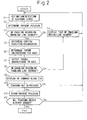
- FIG. 2 is a schematic flow chart of the processing steps carried out after the above estimation/detection of the external force performed inside the robot control unit 2. In the steps, the following processing steps are carried out.
- Step S1 The external force acting upon the front end of the arm of the robot 1 is estimated or detected.
- Step S2 The position of the front end of the robot (front end point 31 of tool) is determined from the positional information of the axes of the robot.
- Step S3 The determined position of the front end of the robot is compared with the copying control enabling regions and enabling line segments set in the block 10 of the enabling region settings, and it is decided whether or not the present robot position belongs to any enabling region or enabling line segment. If NO (the present robot position does not belong to any enabling region or enabling segment), the processing proceeds to step S4, while if YES, the processing proceeds to step S5. In the example shown in FIG. 1, when the front end of the robot belongs to any of the spherical region 15 around the teaching point 14, the cubic region 18 around the teaching point 17, or the region on the line segment 16 (error ⁇ within the previously set range is permitted), the processing proceeds to step S5.
- Step S4 The copying control is not carried out, and "out of enabling region/line segment" is displayed on the displaying means 12 and the processing routine returns to step S1. Further, according to need, the robot is jogged to near the desired teaching point (a position at which YES may be output at step S3) by using the teaching interface 11. Alternatively, the teaching interface 11 is used to move the robot to the desired teaching point (that is, partial execution of the model program). If moving to a position at which YES will be output at step S3, YES is output at step S3 immediately after that, then the processing proceeds to step S5. Note that, while copying control is not carried out, it is also possible not to detect or estimate the external force.
- Step S5 In order to perform the copying control, first, the content of the copying control settings in the region where the robot is currently located is referred to from the content defined in the block 9 of the copying control settings, and the copying direction and orientation (that is, the direction of movement and the direction of change of orientation for following the external force) are determined.
- the content of the copying control settings includes for example "the copying movement is limited to only translation in a direction parallel to the line segment 16 (also the orientation is designated: for example, the orientation from the teaching point 14 toward the teaching point 17), and the rotational movement around the line segment 16", "the copying movement is limited to only translation in a direction parallel to the X-axis of the robot coordinate system (also the orientation is designated: for example +-direction along X-axis) and rotational movement around the X-axis”, etc.
- Step S6 The torque instructions required for performing copying control for only the movement and change of orientation in that direction are determined for the motors of the robot 1.
- the method for following only movement and change of orientation in a specific direction includes a rigidity control of the robot in which a processing using a control loop for controlling the drive of the motors is performed for example for the orthogonal coordinate position of the front end of the robot (front end point 31 of tool) so as to reduce the gain of the result of the processing for only the directions of the movement and the change of orientation to be followed.
- Step S7 The motors of the robot 1 are operated according to the torque instructions to the motors of the robot 1 determined by the copying control means 8. Due to this, the front end of the robot (the front end point 31 of the tool here) operates so as to minimize the external force given by the operator 4 under a condition where the degrees of freedom of motion are limited only to a movement in a specific direction and a change in orientation around a specific axis (change in orientation of the front end point of the tool).
- Step S8 A check similar to that at step S3 is carried out. Namely, it is decided whether or not the robot position after the movement performed by step S7 belongs to any of the copying control enabling regions and enabling line segments defined in the block 10 of the enabling region settings. If NO (it belongs to none of the enabling regions or enabling line segments), the processing returns to step S4, while if YES, the processing proceeds to step S9. Note that when the copying control is normally carried out, usually the output of NO is not issued.
- Step S9 The block (block of command sentences) corresponding to a enabling region in which the robot is currently located or a region or line segment which the robot is approaching among the contents of the model program 19 is displayed on the display means 12 by the block display means 20 (for example, the cursor display). Due to this, the operator 4 can learn which block in the program is being taught at present.
- Step S10 It is checked whether or not the position teaching key 7 was depressed. When it was not depressed, the processing returns to step S1. When it was depressed, the processing proceeds to step S11.
- Step S11 The present position of the robot 1 is taught. Namely, the content of the positional data of the teaching point to which the robot is now heading in the model program is rewritten by the content of the present positional data of the robot.
- Step S12 When the rewriting of the content of the positional data of all teaching points has not been completed, the processing returns to step S1.
- the processing is completed when the rewriting of the content of the positional data of all teaching points has been completed. Note that when re-teaching is necessary, for example the input means 13 is operated, and the processing is started again from step S1.
- the content of the positional data of the teaching points in the model program is sequentially amended whereby the teaching of the robot proceeds. If the deadman's switch 6 is released, the robot 1 is stopped any time by interruption processing and the processing is once ended. However, if the deadman's switch 6 is depressed again, the state immediately before the end of the processing is desirably reproduced by a resume function.
- the display means 12 uses the block display means 20 (for example the cursor display) to display the block (block of command sentences) corresponding to the enabling region in which the robot is currently located or the enabling region or line segment which the robot is approaching among the content of the model program 19 (the newest display content is displayed whenever step S9 comes), therefore the operator 4 can learn which block in the program is being taught at present by viewing that.
- the block display means 20 for example the cursor display
- the robot control unit 2 may be provided with a function by which the copying control is once stopped and then automatically restarted when the present position of the robot approaches within a predetermined distance of a teaching point defined in the model program 19 while performing copying control along a line segment. In this case, it is possible to make the operator 4 sense the resistance and inform him of the approach to the teaching point.
- copying control direction and the block being taught can be freely changed by operation from the input means 13.
- a traditional method of teaching by instructing the direction of operation to the robot by a direction key can be carried out by operation from the input means 13 of the teaching interface 11.
Landscapes
- Engineering & Computer Science (AREA)
- Physics & Mathematics (AREA)
- General Physics & Mathematics (AREA)
- Automation & Control Theory (AREA)
- Robotics (AREA)
- Human Computer Interaction (AREA)
- Manufacturing & Machinery (AREA)
- Numerical Control (AREA)
- Manipulator (AREA)
Abstract
When an operator (4) applies an external force to a
robot (1) via a handle (5) attached to an end portion of
an arm of the robot (1), the external force is estimated
or detected by a force sensor (30) or an acceleration
sensor (40). A copying control means (8) of a robot
control unit (2) determines the position of the tool top
point (31). When the robot (1) is located in a copying
control enabling region (15, 18) or a copying control
enabling line segment (16) defined in a block (10) of
enabling region settings, the copying control is carried
out. The directions of the movement and change of
orientation to be followed are determined with reference
to the content of the copying control settings in the
region where the robot is located at present in the block
(9) of the copying control settings, and the copying
control is carried out for only the movement and change
of orientation in the determined directions, to thereby
move the robot (1).
Description
The present invention relates to a robot
teaching apparatus for teaching an operation to an
industrial robot, and, more particularly, to for example
a robot teaching apparatus suitable for teaching an
operation to a robot used in an application for taking a
shaped article out of a mold.
One of the typical techniques for teaching a
position and an orientation to a robot is the method of
operating the robot by manual operation to make the robot
take a desired position and orientation and thereby
teaching the position and orientation at that time to the
robot (teaching playback method). The conventionally most
generally used method for manually operating a robot in
this way is to operate operation keys (jog movement keys)
provided in a teaching operation panel connected to a
robot control unit.
With this method, however, it is necessary to
designate a direction of movement of the robot by
selectively using a plurality of operation keys
corresponding to the coordinate axes (for example, the X-axis,
Y-axis, and Z-axis of a robot base coordinate
system) and robot axes (for example, J1-axis, J2-axis,...,
and J6-axis). A long time is required for
remembering the correspondence between the operation of
keys and operation directions of the robot. Especially,
when an operator is unfamiliar with the operation, there
is a risk that the robot will end up being made to
collide with a nearby object or the operator himself due
to mistaken operation.
Up to now, no document has been found solving
the above-mentioned defects of the related art and
disclosing a robot teaching apparatus provided with a
simple means enabling an operator to manually operate a
robot to teach a position and orientation to the robot
which enables the operator to teach the robot by making
it move by manual operation in an easily understandable
manner and which reliably prevents the robot from
colliding with a nearby object or the operator at the
time of movement of the robot by the manual operation.
Accordingly, an object of the present invention is
to solve the above-mentioned defects of the related art
and provide a robot teaching apparatus provided with a
simple means enabling an operator to manually operate a
robot to teach a position and orientation to the robot
which enables the operator to teach the robot by making
it move by manual operation by an easily understandable
manner and which reliably prevents the robot from
colliding with a nearby object or the operator at the
time of movement of the robot by the manual operation.
The present invention introduces to movement of a
robot by manual operation a robot control technique
enabling an operator to easily obtain an intuitive grasp
of the direction of movement of the robot by "movement by
copying control", that is, by "moving the robot in
accordance with external force applied to the robot", and
thereby enables learning of the precise robot operation
in a short time and, at the same time, limits the region
in which the robot can be moved by such copying control
to thereby make it possible to easily avoid interference
with a nearby object or the operator. Furthermore, it
enables movement by copying control to be allowed in only
a predetermined direction so as to more reliably prevent
mistaken operation. Note that the reason for the usage of
copying control is that movement of a robot by just the
small external force given by an operator is difficult.
More specifically, the present invention is applied
to a robot teaching apparatus for making a robot move
according to an external force so as to obtain a desired
position and orientation and teaching the position and
orientation of the robot after the movement. Note that
the term "copying control" in the present application
means control of the operation of a robot by using
external force given by an operator etc. as input in
place of operation along contours of a master workpiece
in general copying control. Further, the "position and
orientation of the robot" means the position and
orientation of a point representing the position and
orientation of the robot and typically can be made the
position and orientation of the front end point of a tool
(tool coordinate system), but may be the position and
orientation of a mechanical interface (mechanical
interface coordinate system) affixed to the front end of
an arm as well.
According to the present invention, there is
provided a robot teaching apparatus for moving a robot so
as to obtain desired position and orientation and
teaching the position and orientation of the robot after
the movement, which includes a copying control means for
detecting or estimating an external force applied to the
robot and moving the robot based on the detected or
estimated external force; an enabling region setting
means for setting an enabling region in which movement of
the robot by the copying control means is enabled; and a
means for enabling the copying control by the copying
control means when the robot is located in the set
enabling region.
Preferably, the robot teaching apparatus further
includes a copying control setting means for setting a
restriction that the copying control be carried out in
the enabling region for only one or both of movement in a
predetermined direction and a change in orientation
around a predetermined axis, and the copying control
means executes the copying control according to the set
restriction.
Preferably, the enabling region setting means sets
the enabling region based on positions of teaching points
defined in a previously prepared model teaching program
or positions of previously designated teaching points and
an index representing the size of the region.
Further, the copying control means executes the
copying control only in a direction of a line segment
connecting adjoining teaching points defined in the model
teaching program when a control point of the robot is
located at any teaching point defined in the model
teaching program or on the line segment connecting
adjoining teaching points, so that the copying control
means guides the movement of the robot between adjoining
teaching points along the line segment.
Particularly preferably, the robot teaching
apparatus further includes a means for making the
operator recognize that the robot has approached one of
the teaching points by once stopping the copying control
when the robot approaches within a predetermined distance
of one of the teaching points while executing the copying
control in only the direction of the line segment
connecting adjoining teaching points, and by then
automatically restarting the copying control.
Further, the robot teaching apparatus may further
include a means for displaying a block in the model
teaching program corresponding to one of the teaching
points which the robot is heading toward or one of the
teaching points approached within the predetermined
distance, while executing the copying control in only the
direction of the line segment connecting adjoining
teaching points.
When correcting the positions of the teaching points
defined in the model teaching program, the corrected
teaching program can be used as a new model teaching
program.
The copying control by the copying control means may
be performed by estimating an external force based on
torques and/or speeds of motors for driving axes of the
robot and automatically moving the robot in a direction
where the estimated external force becomes smaller or may
be performed by detecting an external force by a force
sensor attached to the robot and automatically moving the
robot move in a direction where the detected external
force becomes smaller. Alternatively, the copying control
by the copying control means may be performed by
measuring an acceleration by an acceleration sensor
attached to the robot, estimating an external force
applied to the robot based on the measured acceleration
and dynamic parameters including a mass and inertia
moment, and automatically moving the robot in a direction
where the estimated external force becomes smaller.
In each of the above aspects of the invention, a
teaching handle having a deadman's switch and a position
teaching key may be attached to the robot, and the
operator may apply an external force to the teaching
handle.
According to the present invention, by introducing
the technique of copying control for making a robot
operate in accordance with external force in the manual
operation for teaching the position and orientation,
easily intuitively understandable robot operation
consisting of applying external force to move the robot
becomes possible. Further, by restricting the region in
which robot movement by copying control is enabled or
allowing copying movement in only a predetermined
direction, mistaken operation can be reliably prevented.
As a result, the load of the teaching work of the robot
is reduced, and protection of the molds and other nearby
objects and simplification of program adjustment, etc.
become possible.
The above and other objects, features and advantages
of the present invention will be described in more detail
below based on a preferred embodiment of the present
invention with reference to the accompanying drawings, in
which:
An embodiment of the present invention will be
described below with reference to the drawings.
FIG. 1 is a schematic diagram for explaining a
teaching apparatus according to an embodiment of the
present invention. In FIG. 1, a robot manually operated
utilizing copying control is indicated by reference
numeral 1, while an operator manually operating and
teaching the robot 1 is indicated by reference numeral 4.
The robot 1 is controlled by a robot control unit 2
connected to the robot 1.
A tool (here, a hand) 3 is mounted on the front end
of an arm of the robot 1, and the front end point 31 of
the tool is set as the point representing the robot
position. The front end point 31 of the tool represents
the position and orientation of the tool 3. Near the
front end of the arm of the robot 1, a manual operation
handle 5 for the operator 4 to apply external force
(translational force and/or rotational moment) to the
robot 1 is detachably attached to the robot 1. The handle
5 has a deadman's switch 6 and a position teaching key 7.
These are connected to the robot control unit 2 via a
circuit (not shown) built in the operation handle 5.
In addition to the deadman's switch and the position
teaching key, the handle may be provided with keys having
other functions, which may also be connected to the robot
control unit. For example, the handle may be provided
with a jogging movement key, jogging movement lever,
enable switch, alarm release key, DO output key, and/or
coordinate system switching key, which may be connected
to the robot control unit.
The function of the deadman's switch 6 per se is
known. Namely, the operator 4 depresses the deadman's
switch 6 to first set the robot 1 in the operation enable
state. If the operator 4 releases the deadman's switch 6,
the robot 1 immediately stops and the robot 1 will no
longer move even if force is applied to the handle 5 and
the arm of the robot 1. Note that, as will be described
later, even when the deadman's switch 6 is depressed,
movement of the robot 1 in response to external force is
inhibited except when the position of the robot (the
position of the front end point 31 of the tool in the
present example, but also any other point representing
the robot's position and orientation) is within a region
defined so as to enable copying control.
Further, the position teaching key 7 is used when
teaching the present position and orientation of the
robot 1 to the robot control unit 2. Namely, by making
the robot 1 move by the copying control in a manner
described later and depressing the position teaching key
7 when the robot 1 assumes the desired position and
orientation, the position and orientation are taught to
the robot control unit 2.
It is also possible to graphically display the
taught positions and orientations and the path connecting
the teaching points on a display means of the teaching
interface.
Further, it is also possible to add, to the teaching
points, comments, the DO outputs, the copying control
regions and/or other additional information from an input
means of the teaching interface. Here, for the additional
information of teaching points, default values may be
automatically set if selecting the meaning of the
teaching points such as the origin position or standby
position from several options.
Further, if calibrating the coordinates of a molding
machine or other nearby apparatus and the robot in
advance, it is possible to perform the copying control of
the robot and the display and/or editing of the teaching
positions on the coordinate system of the nearby
apparatus.
As will be described below, in some cases, a force
sensor 30 or an acceleration sensor 40 may be attached
near the front end of the arm of the robot 1 and
connected to the robot control unit 2. Further, the robot
control unit 2 may have connected to it a teaching
interface 11 provided with a display means 12 (for
example an LCD) and an input means 13 (for example a
group of n input keys).
The robot control unit 2 is provided with a copying
control means 8 and has blocks of copying control
settings 9, a model program 19, and enabling region
settings 10 which are associated with the copying
controlling means 8. The block of the copying control
settings 9 functions for storing conditions of the
copying control described below, displaying information
of such conditions on the display means 12 of the
teaching interface 11, correcting these conditions
according to instructions manually input from the
teaching interface 11, etc. Note that the conditions of
the copying control preset in the block of the copying
control settings 9 include a "direction of the copying
movement" and a "copying orientation" which are set for
every enabling region described later.
The conditions of the copying control may also
include a setting that the direction of the copying
control be limited to a direction in a preset plane and
the robot be moved by a jogging movement key in a
direction vertical to that preset plane. Further, the
conditions of the copying control may include a setting
that the direction in which the copying control is
enabled not be predetermined and that components of the
external force acting upon the front end of the robot arm
be compared in directions of predetermined coordinate
axes to thereby enable the copying control in the
direction of the coordinate axis in which the component
of the external force is largest or to enable the copying
control in the direction of the coordinate axis in which
the component of the speed of the front end of the robot
arm is largest.
The block of the model program 19 functions for
example for storing various data (particularly the
positional data) of a model program prepared by off-line
programming, displaying information of such data on the
display means 12 of the teaching interface 11, and
correcting these data according to instructions manually
input from the teaching interface 11, etc. Further, the
block of the enabling region settings 10 functions for
storing the content of the settings of the enabling
region corresponding to each teaching position in the
model program and the related data thereof, correcting
these data according to instructions manually input from
the teaching interface 11, etc.
In FIG. 1, as an example, two adjoining teaching
points 14 and 17 (the positional data are given in the
model program) are shown. Further, in relation to these
teaching points 14 and 17, a spherical region 15 having a
radius d1 centered about the teaching point 14 and a
cubic region 18 having sides d2 centered about the
teaching point 17 (geometric center of gravity) are set
as the copying control enabling regions. In general, the
enabling regions can be defined by descriptions using
positions of the teaching points and the geometric
parameters (d1 and d2 are examples thereof).
Further, in relation to these copying control
enabling regions, a line segment 16 heading from the
teaching point 14 to the adjoining teaching point 17 is
set. For this line segment 16 as well, a region treated
in a manner similar to the copying control enabling
region (correctly, a region deemed as if on the line
segment 16 within a range of an error δ) is defined.
Hereinafter, this will be referred to as a "enabling line
segment" for convenience.
The copying control enabling region settings and the
enabling line segment settings may be determined by
acquiring positional information of the nearby apparatus
such as the closed position and opened position of a mold
of the molding machine by communication with the nearby
apparatus and by automatically computation using the
positional information.
The copying control means 8 performs the copying
control of the robot 1 by any method of for example the
following (1) to (4). Note that as these methods of
copying control performed by the copying control means 8
are known, a detailed description thereof will be
omitted.
As described above, the operator 4 can operate the
teaching handle 5 having the deadman's switch 6 and the
position teaching key 7 and the teaching interface 11
having the display means 12 and the input means 13. Note
that the teaching interface 11 may also be given a usual
jog feed operation function for operating the robot when
the copying control is not carried out.
Also, by operating the input means 13 of the
teaching interface 11, the operator 4 can display the
contents of the blocks of the copying control settings 9,
the enabling region settings 10, and the model program 19
or change the data such as the set contents of the
blocks. Further, the operator 4 can grasp and move the
teaching handle 5 to impart force and moment to the robot
1.
Then, when the operator 4 applies force
(translational force and/or moment (the same for the
following description)) to the robot 1 by the handle
operation, the information of the external force is
transferred to the robot control unit 2 by any method
among the above (1) to (4), and the data of the external
force (data of the 6-axis force (force and/or moment)
expressed in the tool coordinate system) applied upon the
front end of the robot arm represented by the front end
point 31 of the tool is acquired.
FIG. 2 is a schematic flow chart of the processing
steps carried out after the above estimation/detection of
the external force performed inside the robot control
unit 2. In the steps, the following processing steps are
carried out.
Step S1: The external force acting upon the front
end of the arm of the robot 1 is estimated or detected.
Step S2: The position of the front end of the robot
(front end point 31 of tool) is determined from the
positional information of the axes of the robot.
Step S3: The determined position of the front end of
the robot is compared with the copying control enabling
regions and enabling line segments set in the block 10 of
the enabling region settings, and it is decided whether
or not the present robot position belongs to any enabling
region or enabling line segment. If NO (the present robot
position does not belong to any enabling region or
enabling segment), the processing proceeds to step S4,
while if YES, the processing proceeds to step S5. In the
example shown in FIG. 1, when the front end of the robot
belongs to any of the spherical region 15 around the
teaching point 14, the cubic region 18 around the
teaching point 17, or the region on the line segment 16
(error δ within the previously set range is permitted),
the processing proceeds to step S5.
Step S4: The copying control is not carried out, and
"out of enabling region/line segment" is displayed on the
displaying means 12 and the processing routine returns to
step S1. Further, according to need, the robot is jogged
to near the desired teaching point (a position at which
YES may be output at step S3) by using the teaching
interface 11. Alternatively, the teaching interface 11 is
used to move the robot to the desired teaching point
(that is, partial execution of the model program). If
moving to a position at which YES will be output at step
S3, YES is output at step S3 immediately after that, then
the processing proceeds to step S5. Note that, while
copying control is not carried out, it is also possible
not to detect or estimate the external force.
Step S5: In order to perform the copying control,
first, the content of the copying control settings in the
region where the robot is currently located is referred
to from the content defined in the block 9 of the copying
control settings, and the copying direction and
orientation (that is, the direction of movement and the
direction of change of orientation for following the
external force) are determined. The content of the
copying control settings includes for example "the
copying movement is limited to only translation in a
direction parallel to the line segment 16 (also the
orientation is designated: for example, the orientation
from the teaching point 14 toward the teaching point 17),
and the rotational movement around the line segment 16",
"the copying movement is limited to only translation in a
direction parallel to the X-axis of the robot coordinate
system (also the orientation is designated: for example
+-direction along X-axis) and rotational movement around
the X-axis", etc.
Step S6: The torque instructions required for
performing copying control for only the movement and
change of orientation in that direction are determined
for the motors of the robot 1.
Note that the method for following only movement and
change of orientation in a specific direction includes a
rigidity control of the robot in which a processing using
a control loop for controlling the drive of the motors is
performed for example for the orthogonal coordinate
position of the front end of the robot (front end point
31 of tool) so as to reduce the gain of the result of the
processing for only the directions of the movement and
the change of orientation to be followed.
Step S7: The motors of the robot 1 are operated
according to the torque instructions to the motors of the
robot 1 determined by the copying control means 8. Due to
this, the front end of the robot (the front end point 31
of the tool here) operates so as to minimize the external
force given by the operator 4 under a condition where the
degrees of freedom of motion are limited only to a
movement in a specific direction and a change in
orientation around a specific axis (change in orientation
of the front end point of the tool).
Step S8: A check similar to that at step S3 is
carried out. Namely, it is decided whether or not the
robot position after the movement performed by step S7
belongs to any of the copying control enabling regions
and enabling line segments defined in the block 10 of the
enabling region settings. If NO (it belongs to none of
the enabling regions or enabling line segments), the
processing returns to step S4, while if YES, the
processing proceeds to step S9. Note that when the
copying control is normally carried out, usually the
output of NO is not issued.
Step S9: The block (block of command sentences)
corresponding to a enabling region in which the robot is
currently located or a region or line segment which the
robot is approaching among the contents of the model
program 19 is displayed on the display means 12 by the
block display means 20 (for example, the cursor display).
Due to this, the operator 4 can learn which block in the
program is being taught at present.
Step S10: It is checked whether or not the position
teaching key 7 was depressed. When it was not depressed,
the processing returns to step S1. When it was depressed,
the processing proceeds to step S11.
Step S11: The present position of the robot 1 is
taught. Namely, the content of the positional data of the
teaching point to which the robot is now heading in the
model program is rewritten by the content of the present
positional data of the robot.
Step S12: When the rewriting of the content of the
positional data of all teaching points has not been
completed, the processing returns to step S1. The
processing is completed when the rewriting of the content
of the positional data of all teaching points has been
completed. Note that when re-teaching is necessary, for
example the input means 13 is operated, and the
processing is started again from step S1.
By repeating such a process, the content of the
positional data of the teaching points in the model
program is sequentially amended whereby the teaching of
the robot proceeds. If the deadman's switch 6 is
released, the robot 1 is stopped any time by interruption
processing and the processing is once ended. However, if
the deadman's switch 6 is depressed again, the state
immediately before the end of the processing is desirably
reproduced by a resume function.
Further, while the robot operation and teaching are
proceeding, the display means 12 uses the block display
means 20 (for example the cursor display) to display the
block (block of command sentences) corresponding to the
enabling region in which the robot is currently located
or the enabling region or line segment which the robot is
approaching among the content of the model program 19
(the newest display content is displayed whenever step S9
comes), therefore the operator 4 can learn which block in
the program is being taught at present by viewing that.
Further, the robot control unit 2 may be provided
with a function by which the copying control is once
stopped and then automatically restarted when the present
position of the robot approaches within a predetermined
distance of a teaching point defined in the model program
19 while performing copying control along a line segment.
In this case, it is possible to make the operator 4 sense
the resistance and inform him of the approach to the
teaching point.
Further, the copying control direction and the block
being taught can be freely changed by operation from the
input means 13. Also, a traditional method of teaching by
instructing the direction of operation to the robot by a
direction key can be carried out by operation from the
input means 13 of the teaching interface 11.
While the present invention has been described with
reference to specific embodiments shown in the
accompanying drawings, these embodiments are for
explanatory and are not limitative. Therefore, the scope
of the present invention is only restricted by the
claims. The preferred embodiments of the present
invention may be modified or changed in any way without
departing from the scope of the claims.
Claims (11)
- A robot teaching apparatus for moving a robot (1) so as to obtain desired position and orientation and teaching the position and orientation of said robot after the movement, said robot teaching apparatus characterized in that said robot teaching apparatus comprising:a copying control means (8) for detecting or estimating an external force applied to said robot (1) and moving said robot (1) based on the detected or estimated external force;an enabling region setting means (10) for setting an enabling region (15; 18) in which movement of said robot (1) by said copying control means (8) is enabled; anda means for enabling the copying control by said copying control means (8) when said robot (1) is located in the set enabling region (15; 18).
- The robot teaching apparatus according to claim 1, wherein said robot teaching apparatus further comprises a copying control setting means (9) for setting a restriction that the copying control be carried out in the enabling region (15; 18) for only one or both of movement in a predetermined direction and a change in orientation around a predetermined axis, and said copying control means (8) executes the copying control according to the set restriction.
- The robot teaching apparatus according to claim 1 or 2, wherein said enabling region setting means (10) sets the enabling region (15; 18) based on positions of teaching points (14; 17) defined in a previously prepared model teaching program (19) or positions of previously designated teaching points (14; 17) and an index representing the size of the region.
- The robot teaching apparatus according to claim 3, wherein said copying control means (8) executes the copying control only in a direction of a line segment (16) connecting adjoining teaching points (14; 17) defined in said model teaching program (19) when a control point of said robot (1) is located at any teaching point (14; 17) defined in said model teaching program (19) or on said line segment (16) connecting said adjoining teaching points (14; 17), so that said copying control means guides the movement of said robot (1) between said adjoining teaching points (14; 17) along said line segment (16).
- The robot teaching apparatus according to claim 4, further comprising a means for making the operator recognize that said robot (1) has approached one of said teaching points (14; 17) by once stopping the copying control when said robot approaches within a predetermined distance of said one of said teaching points (14; 17) while executing the copying control in only the direction of said line segment (16) connecting adjoining teaching points (14; 17), and by then automatically restarting the copying control.
- The robot teaching apparatus according to claim 4 or 5, further comprising a means (20) for displaying a block in said model teaching program (19) corresponding to one of said teaching points (14; 17) which said robot is heading toward or one of said teaching points (14; 17) approached within a predetermined distance, while executing the copying control in only the direction of said line segment (16) connecting adjoining teaching points (14; 17).
- The robot teaching apparatus according to any one of claims 3 to 6, wherein the positions of said teaching points (14; 17) defined in said model teaching program (19) is corrected to prepare a corrected teaching program which is used as a new model teaching program.
- The robot teaching apparatus according to any one of claims 1 to 7, wherein said copying control means (8) estimates an external force based on one or both of torques and speeds of motors for driving axes of said robot (1) and automatically move said robot in a direction where the estimated external force becomes smaller.
- The robot teaching apparatus according to any one of claims 1 to 7, wherein said copying control means (8) detects an external force by a force sensor (30) attached to said robot (1) and automatically moves said robot (1) in a direction where the detected external force becomes smaller.
- The robot teaching apparatus according to any one of claims 1 to 7, wherein said copying control means (8) measures an acceleration by an acceleration sensor (40) attached to said robot (1), estimates an external force applied to said robot (1) based on the measured acceleration and dynamic parameters including a mass and inertia moment, and automatically moves said robot (1) in a direction where the estimated external force becomes smaller.
- The robot teaching apparatus according to any one of claims 1 to 10, wherein a teaching handle (5) having a deadman's switch (6) and a position teaching key (7) is attached to said robot (1), and the operator applies an external force to said teaching handle (5).
Applications Claiming Priority (2)
| Application Number | Priority Date | Filing Date | Title |
|---|---|---|---|
| JP2004105791 | 2004-03-31 | ||
| JP2004105791A JP3923053B2 (en) | 2004-03-31 | 2004-03-31 | Robot teaching device |
Publications (1)
| Publication Number | Publication Date |
|---|---|
| EP1582955A2 true EP1582955A2 (en) | 2005-10-05 |
Family
ID=34880078
Family Applications (1)
| Application Number | Title | Priority Date | Filing Date |
|---|---|---|---|
| EP05006910A Withdrawn EP1582955A2 (en) | 2004-03-31 | 2005-03-30 | Robot teaching apparatus |
Country Status (6)
| Country | Link |
|---|---|
| US (1) | US20050222714A1 (en) |
| EP (1) | EP1582955A2 (en) |
| JP (1) | JP3923053B2 (en) |
| KR (1) | KR100741618B1 (en) |
| CN (1) | CN100336637C (en) |
| TW (1) | TWI276933B (en) |
Cited By (4)
| Publication number | Priority date | Publication date | Assignee | Title |
|---|---|---|---|---|
| EP2131257A1 (en) * | 2008-06-06 | 2009-12-09 | KUKA Roboter GmbH | Method and device for controlling a manipulator |
| EP2431138A4 (en) * | 2009-01-09 | 2014-06-04 | Panasonic Corp | CONTROL APPARATUS AND CONTROL METHOD FOR ROBOTIC ARM, ROBOT, CONTROL PROGRAM FOR ROBOTIC ARM, AND INTEGRATED ELECTRONIC CIRCUIT |
| WO2017036520A1 (en) * | 2015-09-02 | 2017-03-09 | Abb Schweiz Ag | System and method for generating a robot program with a hand-held teaching device |
| US10478965B2 (en) | 2017-03-31 | 2019-11-19 | Fanuc Corporation | Robot system |
Families Citing this family (86)
| Publication number | Priority date | Publication date | Assignee | Title |
|---|---|---|---|---|
| JP4553203B2 (en) * | 2005-08-01 | 2010-09-29 | 国立大学法人 名古屋工業大学 | Work assistance device |
| JP2007038059A (en) * | 2005-08-01 | 2007-02-15 | Nagoya Institute Of Technology | Work assistance device |
| JP4171488B2 (en) * | 2005-12-16 | 2008-10-22 | ファナック株式会社 | Offline programming device |
| JP4873253B2 (en) * | 2007-09-18 | 2012-02-08 | 株式会社安川電機 | Robot direct teaching device |
| CN101425149B (en) * | 2007-11-02 | 2010-10-13 | 阿丹电子企业股份有限公司 | Device and method for monitoring personal action safety by using electronic tag tape |
| CN101909829B (en) | 2008-02-28 | 2012-08-29 | 松下电器产业株式会社 | Robot arm control device and control method, robot, robot arm control program, and integrated electronic circuit for robot arm control |
| JP5163299B2 (en) * | 2008-06-04 | 2013-03-13 | 株式会社Ihi | Robot controller |
| WO2009157733A1 (en) * | 2008-06-27 | 2009-12-30 | Yujin Robot Co., Ltd. | Interactive learning system using robot and method of operating the same in child education |
| JP5293039B2 (en) * | 2008-09-19 | 2013-09-18 | 株式会社安川電機 | Robot system and robot control method |
| EP2194434B1 (en) * | 2008-12-05 | 2012-05-30 | COMAU SpA | Robot system |
| JP5509673B2 (en) * | 2009-05-22 | 2014-06-04 | 株式会社Ihi | Robot control apparatus and control method thereof |
| KR101100108B1 (en) | 2010-02-26 | 2011-12-29 | 주식회사 엔티리서치 | Teaching apparatus and direct teaching apparatus provided with the same |
| US20120078415A1 (en) * | 2010-03-17 | 2012-03-29 | Hiroyasu Kubo | Parallel link robot, and method of teaching parallel link robot |
| CN101833892A (en) * | 2010-04-30 | 2010-09-15 | 东南大学 | Embedded teaching programming device and method for welding robot |
| AT509927B1 (en) * | 2010-06-08 | 2015-05-15 | Keba Ag | METHOD FOR PROGRAMMING OR PRESENTING MOVEMENTS OR RUNS OF AN INDUSTRIAL ROBOT |
| CN102725109B (en) * | 2010-07-27 | 2015-03-18 | 松下电器产业株式会社 | Moving route searching device and moving route searching method |
| CN102568269A (en) * | 2010-12-30 | 2012-07-11 | 沈阳新松机器人自动化股份有限公司 | Control system with teach box function |
| CN102950596B (en) * | 2011-08-23 | 2015-11-11 | 松下电器产业株式会社 | Parallel link robot and action teaching method thereof |
| KR101305819B1 (en) * | 2012-01-04 | 2013-09-06 | 현대자동차주식회사 | Manipulating intention torque extracting method of wearable robot |
| CN102622937A (en) * | 2012-03-08 | 2012-08-01 | 南京埃斯顿机器人工程有限公司 | Robot demonstrator |
| CN102658549A (en) * | 2012-05-10 | 2012-09-12 | 上海理工大学 | Six-axis industrial robot control system with PLC (programmable logic control) function |
| WO2014110682A1 (en) | 2013-01-18 | 2014-07-24 | Robotiq Inc. | Force/torque sensor, apparatus and method for robot teaching and operation |
| CN103085071A (en) * | 2013-02-04 | 2013-05-08 | 惠州市东扬科技有限公司 | Visualized robot program compiling method |
| CN118717295A (en) | 2013-03-15 | 2024-10-01 | 史赛克公司 | End effector of surgical robot arm |
| JP5673717B2 (en) * | 2013-03-19 | 2015-02-18 | 株式会社安川電機 | Robot system and method of manufacturing workpiece |
| US9980785B2 (en) | 2013-10-24 | 2018-05-29 | Auris Health, Inc. | Instrument device manipulator with surgical tool de-articulation |
| CN105939647B (en) | 2013-10-24 | 2020-01-21 | 奥瑞斯健康公司 | Robot-assisted endovascular surgery system and related methods |
| JP5893665B2 (en) * | 2014-04-14 | 2016-03-23 | ファナック株式会社 | Robot control device for controlling a robot to be moved according to an applied force |
| JP5893666B2 (en) | 2014-04-14 | 2016-03-23 | ファナック株式会社 | Robot control device and robot system for robots that move according to force |
| JP5893664B2 (en) | 2014-04-14 | 2016-03-23 | ファナック株式会社 | Robot control device for controlling a robot to be moved according to an applied force |
| JP6193816B2 (en) | 2014-06-20 | 2017-09-06 | ファナック株式会社 | Articulated robot with arm retracting function |
| US9788910B2 (en) | 2014-07-01 | 2017-10-17 | Auris Surgical Robotics, Inc. | Instrument-mounted tension sensing mechanism for robotically-driven medical instruments |
| US10792464B2 (en) | 2014-07-01 | 2020-10-06 | Auris Health, Inc. | Tool and method for using surgical endoscope with spiral lumens |
| EP3182951A1 (en) * | 2014-08-18 | 2017-06-28 | Ondal Medical Systems GmbH | Force- or movement-reactive stand device, controller, and method for positioning the stand device |
| TWI502296B (en) * | 2014-08-27 | 2015-10-01 | Hiwin Tech Corp | Teaching device for robot |
| JP6660102B2 (en) * | 2014-08-27 | 2020-03-04 | キヤノン株式会社 | Robot teaching device and control method thereof, robot system, program |
| JP6416560B2 (en) | 2014-09-11 | 2018-10-31 | 株式会社デンソー | Positioning control device |
| US9737371B2 (en) | 2014-09-30 | 2017-08-22 | Auris Surgical Robotics, Inc. | Configurable robotic surgical system with virtual rail and flexible endoscope |
| CN104308850B (en) * | 2014-10-09 | 2015-12-23 | 南京工业职业技术学院 | A kind of manipulator teaching 3D sensing handle |
| US9804593B1 (en) * | 2014-12-12 | 2017-10-31 | X Development Llc | Methods and systems for teaching positions to components of devices |
| US9592608B1 (en) * | 2014-12-15 | 2017-03-14 | X Development Llc | Methods and systems for providing feedback during teach mode |
| JP6081981B2 (en) * | 2014-12-19 | 2017-02-15 | ファナック株式会社 | Numerical control device having automatic display means of teaching program |
| DK3277467T3 (en) * | 2015-03-31 | 2020-07-27 | Abb Schweiz Ag | PROCEDURE TO CONTROL AN INDUSTRIAL ROBOT BY TOUCH |
| WO2016161444A1 (en) * | 2015-04-03 | 2016-10-06 | Think Surgical, Inc. | Robotic system with intuitive motion control |
| JP6088583B2 (en) | 2015-06-08 | 2017-03-01 | ファナック株式会社 | Robot controller with robot and force display function |
| DE102015009151A1 (en) * | 2015-07-14 | 2017-01-19 | Kuka Roboter Gmbh | Determining an input command for a robot that is input to the robot by manually applying a force |
| AU2016321332B2 (en) | 2015-09-09 | 2020-10-08 | Auris Health, Inc. | Instrument device manipulator for a surgical robotics system |
| JP6489991B2 (en) | 2015-10-02 | 2019-03-27 | ファナック株式会社 | Robot operating device having a handle for operating the robot |
| DE102015012959B4 (en) * | 2015-10-08 | 2019-01-17 | Franka Emika Gmbh | Robot system and method for controlling a robot system |
| CN108025439B (en) * | 2015-10-14 | 2021-04-27 | 川崎重工业株式会社 | Robot teaching method and robot arm control device |
| FR3043004B1 (en) * | 2015-10-29 | 2017-12-22 | Airbus Group Sas | METHOD FOR ORIENTATION OF AN EFFECTOR WITH AN ASSEMBLY TOOL IN RELATION TO A SURFACE |
| JP6706489B2 (en) * | 2015-11-24 | 2020-06-10 | 川崎重工業株式会社 | Robot direct teaching method |
| US9919422B1 (en) | 2016-01-06 | 2018-03-20 | X Development Llc | Methods and systems to provide mechanical feedback during movement of a robotic system |
| AT518481B1 (en) * | 2016-03-07 | 2018-09-15 | Keba Ag | System and method for the spatial movement of an object |
| JP6733239B2 (en) * | 2016-03-18 | 2020-07-29 | セイコーエプソン株式会社 | Controller and robot system |
| JP6746990B2 (en) * | 2016-03-18 | 2020-08-26 | セイコーエプソン株式会社 | Robot controller and robot system |
| TWI805545B (en) * | 2016-04-12 | 2023-06-21 | 丹麥商環球機器人公司 | Method and computer program product for programming a robot by demonstration |
| CN105690421A (en) * | 2016-04-21 | 2016-06-22 | 奇弩(北京)科技有限公司 | Universal mechanical arm capable of automatically memorizing trajectory |
| KR102048820B1 (en) * | 2016-11-28 | 2019-11-26 | 한국기계연구원 | Assembly teaching method using passive compliance gripper |
| CN108115711A (en) * | 2016-11-29 | 2018-06-05 | 沈阳新松机器人自动化股份有限公司 | A kind of teaching system of robot |
| CN106737691A (en) * | 2017-02-07 | 2017-05-31 | 珠海金萝卜智动科技有限公司 | The method and apparatus of manual teaching robot |
| CN110612181B (en) * | 2017-02-17 | 2023-05-23 | Abb瑞士股份有限公司 | Method for controlling an industrial robot during robot guidance through programming and the industrial robot |
| CN108621155B (en) * | 2017-03-21 | 2023-04-07 | 精工爱普生株式会社 | Control devices, teaching devices and robot systems |
| JP7106874B2 (en) * | 2017-03-21 | 2022-07-27 | セイコーエプソン株式会社 | Control device, teaching device, and robot system |
| JP2018176288A (en) * | 2017-04-03 | 2018-11-15 | ファナック株式会社 | Teaching device of robot |
| WO2019102562A1 (en) * | 2017-11-22 | 2019-05-31 | 三菱電機株式会社 | Display actuator and cobot |
| CN109986238B (en) * | 2017-12-29 | 2021-02-26 | 深圳中集智能科技有限公司 | Robot linear flexible operation vision fuzzy profiling control method |
| JP7091777B2 (en) * | 2018-03-30 | 2022-06-28 | 株式会社安川電機 | Robot system and control method |
| JP7048176B2 (en) * | 2018-05-23 | 2022-04-05 | アズビル株式会社 | Robot direct teaching device and direct teaching method |
| JP7263724B2 (en) * | 2018-09-27 | 2023-04-25 | 株式会社デンソーウェーブ | Robot control method |
| EP3646839A1 (en) | 2018-11-05 | 2020-05-06 | Ondal Medical Systems GmbH | Support arm system for a medical device, method for operating a support arm system and a method for forming a support arm system |
| JP7053443B2 (en) * | 2018-12-07 | 2022-04-12 | ファナック株式会社 | Control device for robots that perform manual operations with the operating device |
| CN111300433A (en) * | 2018-12-11 | 2020-06-19 | 沈阳新松机器人自动化股份有限公司 | Robot dragging teaching device based on six-dimensional force sensor |
| EP3747604B1 (en) * | 2019-06-07 | 2022-01-26 | Robert Bosch GmbH | Robot device controller, robot device arrangement and method for controlling a robot device |
| CN110653801B (en) * | 2019-09-30 | 2022-06-17 | 哈尔滨工业大学 | Guide control system of robot operating arm and flexible control and teaching learning method thereof |
| JP7388870B2 (en) * | 2019-10-18 | 2023-11-29 | ファナック株式会社 | Robot systems and control equipment |
| TWI725630B (en) | 2019-11-21 | 2021-04-21 | 財團法人工業技術研究院 | Processing path generating device and method thereof |
| TWI805978B (en) * | 2020-12-22 | 2023-06-21 | 達明機器人股份有限公司 | Two loops torque sensing system and sensing method thereof |
| CN112846737A (en) * | 2021-01-07 | 2021-05-28 | 深圳市驰速自动化设备有限公司 | Software control system for dragging demonstration automatic screw locking machine |
| EP4295200A4 (en) * | 2021-02-17 | 2024-12-25 | Avridh Technologies, Inc. | System and method of controlling navigation of robot in dynamic environment based on heuristic learning |
| DE112022000541B4 (en) | 2021-03-17 | 2026-04-30 | Fanuc Corporation | Robot actuation device and robot |
| KR102513381B1 (en) * | 2021-04-15 | 2023-03-22 | 충남대학교산학협력단 | Torque and posture-based robot teaching method using multimodal sensing |
| JP7108761B1 (en) * | 2021-07-26 | 2022-07-28 | 日鉄エンジニアリング株式会社 | Control system, control method and program |
| KR102682481B1 (en) * | 2022-08-30 | 2024-07-04 | 한국로봇융합연구원 | Master arm device for remotely manipulating the manipulator in the vacuum chamber |
| CN116810772A (en) * | 2023-03-13 | 2023-09-29 | 常州精控电机电器有限公司 | A servo motor control method to realize linear motion of the end of a robotic arm |
| WO2025163746A1 (en) * | 2024-01-30 | 2025-08-07 | ファナック株式会社 | Robot control device |
Family Cites Families (14)
| Publication number | Priority date | Publication date | Assignee | Title |
|---|---|---|---|---|
| DE3240251A1 (en) * | 1982-10-30 | 1984-05-03 | Deutsche Forschungs- und Versuchsanstalt für Luft- und Raumfahrt e.V., 5000 Köln | METHOD FOR PROGRAMMING MOVEMENTS AND, IF REQUIRED, MACHINING FORCES OR -MOMENTS OF A ROBOT OR MANIPULATOR AND DEVICE FOR CARRYING OUT THIS |
| US4462812A (en) * | 1982-12-08 | 1984-07-31 | General Motors Corporation | Ceramic monolith particulate trap including filter support |
| JPS59115149A (en) * | 1982-12-22 | 1984-07-03 | Fanuc Ltd | Control method for traced machining |
| GB2229296B (en) * | 1989-03-03 | 1993-08-11 | Mitsubishi Heavy Ind Ltd | Teaching playback type robot |
| JP2895672B2 (en) * | 1992-01-28 | 1999-05-24 | ファナック株式会社 | Multiple robot control method |
| US5495410A (en) * | 1994-08-12 | 1996-02-27 | Minnesota Mining And Manufacturing Company | Lead-through robot programming system |
| KR0151017B1 (en) * | 1994-12-28 | 1999-01-15 | 김광호 | Robot teaching device & method |
| US5980082A (en) * | 1995-07-05 | 1999-11-09 | Fanuc Limited | Robot movement control device and movement control method |
| KR100449429B1 (en) * | 1995-09-14 | 2004-12-13 | 가부시키가이샤 야스가와덴끼 | Robot teaching device |
| JPH09141580A (en) * | 1995-11-22 | 1997-06-03 | Yaskawa Electric Corp | Direct teaching robot movement range limiting device |
| IL120889A (en) * | 1997-05-22 | 1998-10-30 | Eshed Robotec 1982 Ltd | Method and apparatus for the direct teaching of automatic machines |
| DE19814630B4 (en) * | 1998-03-26 | 2011-09-29 | Carl Zeiss | Method and apparatus for manually controlled guiding a tool in a predetermined range of motion |
| US6385508B1 (en) * | 2000-10-31 | 2002-05-07 | Fanuc Robotics North America, Inc. | Lead-through teach handle assembly and method of teaching a robot assembly |
| CA2633137C (en) * | 2002-08-13 | 2012-10-23 | The Governors Of The University Of Calgary | Microsurgical robot system |
-
2004
- 2004-03-31 JP JP2004105791A patent/JP3923053B2/en not_active Expired - Fee Related
-
2005
- 2005-03-28 CN CNB2005100588071A patent/CN100336637C/en not_active Expired - Fee Related
- 2005-03-30 KR KR1020050026250A patent/KR100741618B1/en not_active Expired - Fee Related
- 2005-03-30 TW TW094109963A patent/TWI276933B/en not_active IP Right Cessation
- 2005-03-30 EP EP05006910A patent/EP1582955A2/en not_active Withdrawn
- 2005-03-31 US US11/094,688 patent/US20050222714A1/en not_active Abandoned
Cited By (5)
| Publication number | Priority date | Publication date | Assignee | Title |
|---|---|---|---|---|
| EP2131257A1 (en) * | 2008-06-06 | 2009-12-09 | KUKA Roboter GmbH | Method and device for controlling a manipulator |
| EP2431138A4 (en) * | 2009-01-09 | 2014-06-04 | Panasonic Corp | CONTROL APPARATUS AND CONTROL METHOD FOR ROBOTIC ARM, ROBOT, CONTROL PROGRAM FOR ROBOTIC ARM, AND INTEGRATED ELECTRONIC CIRCUIT |
| WO2017036520A1 (en) * | 2015-09-02 | 2017-03-09 | Abb Schweiz Ag | System and method for generating a robot program with a hand-held teaching device |
| US10478965B2 (en) | 2017-03-31 | 2019-11-19 | Fanuc Corporation | Robot system |
| DE102018107069B4 (en) | 2017-03-31 | 2020-08-06 | Fanuc Corporation | Robot system |
Also Published As
| Publication number | Publication date |
|---|---|
| TWI276933B (en) | 2007-03-21 |
| TW200602829A (en) | 2006-01-16 |
| US20050222714A1 (en) | 2005-10-06 |
| CN100336637C (en) | 2007-09-12 |
| CN1676287A (en) | 2005-10-05 |
| KR100741618B1 (en) | 2007-07-23 |
| KR20060044963A (en) | 2006-05-16 |
| JP3923053B2 (en) | 2007-05-30 |
| JP2005293098A (en) | 2005-10-20 |
Similar Documents
| Publication | Publication Date | Title |
|---|---|---|
| US20050222714A1 (en) | Robot teaching apparatus | |
| US6124693A (en) | Robot controller | |
| US10259118B2 (en) | Robot system having function of simplifying teaching operation and improving operating performance by learning | |
| JP4122652B2 (en) | Robot control device | |
| US10118295B2 (en) | Manual feed apparatus of robot for calculating operable range of robot | |
| JP3708083B2 (en) | Robot teaching device | |
| CN107336244B (en) | Intuitive force guiding method and device for robot | |
| US10773349B2 (en) | Machine tool and control method for machine tool | |
| JP2013136123A (en) | Assisting device and assisting method for teaching operation for robot | |
| CN118269089A (en) | Method for motion simulation of manipulator | |
| JPH10207519A (en) | Robot control system | |
| CN108687758B (en) | Moving speed control device and method for robot | |
| JPH0337701A (en) | Method and device for robot control | |
| JP2739354B2 (en) | Teaching method in three-dimensional laser beam machine | |
| US20250135638A1 (en) | Work robot system | |
| JP2003015713A (en) | Numerical control unit | |
| JPH1177572A (en) | Robot control device | |
| JP2635106B2 (en) | Robot work area limiting device | |
| JPH08161025A (en) | Teaching device | |
| JP2507957B2 (en) | Movement control device for industrial robot | |
| JP2025008168A (en) | Robot control device and robot control method | |
| JPH03113512A (en) | Teaching method for industrial robots | |
| JP5547601B2 (en) | Numerical controller | |
| JPH1177574A (en) | Robot control device | |
| JPH0887329A (en) | Positioning control unit |
Legal Events
| Date | Code | Title | Description |
|---|---|---|---|
| PUAI | Public reference made under article 153(3) epc to a published international application that has entered the european phase |
Free format text: ORIGINAL CODE: 0009012 |
|
| AK | Designated contracting states |
Kind code of ref document: A2 Designated state(s): AT BE BG CH CY CZ DE DK EE ES FI FR GB GR HU IE IS IT LI LT LU MC NL PL PT RO SE SI SK TR |
|
| AX | Request for extension of the european patent |
Extension state: AL BA HR LV MK YU |
|
| STAA | Information on the status of an ep patent application or granted ep patent |
Free format text: STATUS: THE APPLICATION HAS BEEN WITHDRAWN |
|
| 18W | Application withdrawn |
Effective date: 20090821 |