EP1582852A2 - Pressure sensor - Google Patents
Pressure sensor Download PDFInfo
- Publication number
- EP1582852A2 EP1582852A2 EP05006428A EP05006428A EP1582852A2 EP 1582852 A2 EP1582852 A2 EP 1582852A2 EP 05006428 A EP05006428 A EP 05006428A EP 05006428 A EP05006428 A EP 05006428A EP 1582852 A2 EP1582852 A2 EP 1582852A2
- Authority
- EP
- European Patent Office
- Prior art keywords
- diaphragm
- sensor
- pressure
- displacement
- monitor
- Prior art date
- Legal status (The legal status is an assumption and is not a legal conclusion. Google has not performed a legal analysis and makes no representation as to the accuracy of the status listed.)
- Withdrawn
Links
Images



Classifications
-
- G—PHYSICS
- G01—MEASURING; TESTING
- G01L—MEASURING FORCE, STRESS, TORQUE, WORK, MECHANICAL POWER, MECHANICAL EFFICIENCY, OR FLUID PRESSURE
- G01L11/00—Measuring steady or quasi-steady pressure of a fluid or a fluent solid material by means not provided for in group G01L7/00 or G01L9/00
- G01L11/02—Measuring steady or quasi-steady pressure of a fluid or a fluent solid material by means not provided for in group G01L7/00 or G01L9/00 by optical means
-
- G—PHYSICS
- G01—MEASURING; TESTING
- G01L—MEASURING FORCE, STRESS, TORQUE, WORK, MECHANICAL POWER, MECHANICAL EFFICIENCY, OR FLUID PRESSURE
- G01L9/00—Measuring steady of quasi-steady pressure of fluid or fluent solid material by electric or magnetic pressure-sensitive elements; Transmitting or indicating the displacement of mechanical pressure-sensitive elements, used to measure the steady or quasi-steady pressure of a fluid or fluent solid material, by electric or magnetic means
- G01L9/0041—Transmitting or indicating the displacement of flexible diaphragms
- G01L9/0072—Transmitting or indicating the displacement of flexible diaphragms using variations in capacitance
-
- G—PHYSICS
- G01—MEASURING; TESTING
- G01L—MEASURING FORCE, STRESS, TORQUE, WORK, MECHANICAL POWER, MECHANICAL EFFICIENCY, OR FLUID PRESSURE
- G01L9/00—Measuring steady of quasi-steady pressure of fluid or fluent solid material by electric or magnetic pressure-sensitive elements; Transmitting or indicating the displacement of mechanical pressure-sensitive elements, used to measure the steady or quasi-steady pressure of a fluid or fluent solid material, by electric or magnetic means
- G01L9/0041—Transmitting or indicating the displacement of flexible diaphragms
- G01L9/0076—Transmitting or indicating the displacement of flexible diaphragms using photoelectric means
- G01L9/0077—Transmitting or indicating the displacement of flexible diaphragms using photoelectric means for measuring reflected light
Definitions
- the invention relates to high sensitivity, high bandwidth, low pressure sensors and, more particularly, to the application of these devices in air gauges for use in, for example, lithography devices.
- the present invention is directed to high sensitivity, low pressure air gauges having higher bandwidths than are presently available.
- a pressure sensor in accordance with the invention includes a diaphragm having a substantially rigid outer portion and a displaceable inner portion that displaces in response to a pressure difference between first and second sides of the diaphragm.
- the pressure gauge further includes a sensor located proximate to the diaphragm and adapted to sense the displacement of the diaphragm inner portion.
- the pressure gauge further includes a monitor and control systems coupled to the sensor (wired or wireless), and adapted to determine the pressure difference from the displacement of the diaphragm.
- the present invention provides a variety of optional sensing designs including, without limitation, optical sensing designs and capacitive sensing designs.
- the operational pressure range of the sensor is approximately 0.1 to 0.5 inches of water.
- the diaphragm and sensor have a relatively high bandwidth and can thus be implemented in relatively high speed applications.
- the invention can be implemented in, for example, lithography proximity sensing equipment and lithography topographical mapping equipment.
- FIG. 1 is a side plan view of a pressure sensor 100, including a diaphragm 102 and a sensor 104.
- FIG. 2A is a front plan view of the diaphragm 102.
- FIG. 2B is a side plan view of a substantially rigid outer portion 202 of the diaphragm 102.
- FIG. 2C is a side plan view of the diaphragm 102, including the substantially rigid outer portion 202, an inner portion 204, and a proximity sensor surface 206 shown distended as if under a differential pressure condition.
- FIG. 3 is a side perspective view of the pressure sensor 100, wherein the sensor 104 and a monitor and control system 106 are implemented with a white-light interferometer.
- FIG. 4 is a side plan view of the pressure sensor 100, wherein the sensor 104 and the monitor and control system 106 are implemented with an optical grazing angle sensor.
- FIG. 5 is a side plan view of the pressure sensor 100, wherein the sensor 104 includes a capacitive sensor 502, and the proximity surface 206 includes a grounded plate 504.
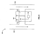
- FIG. 6 is a side plan view of an air system 600, including a first leg 602 and a second leg 604, and the pressure sensor 100 positioned in a bridge therebetween.
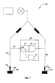
- FIG. 7 is a side plan view of the pressure sensor 100 implemented in a proximity sensor 700 used in, for example, lithography.
- FIG. 8 is a side plan view of the pressure sensor 100 implemented in a proximity sensor 800.
- the present invention is directed to low pressure air gauges having higher bandwidths than are presently available.
- the present invention can be used in, for example, and without limitation, lithography proximity sensing and lithography topographical mapping.
- FIG. 1 is a side plan view of a pressure sensor 100 including a flexing plate or diaphragm 102, a diaphragm displacement sensor 104 (hereinafter “sensor” 104) located proximate to the diaphragm 102, and a monitor and control system 106 electrically coupled (wired or wireless) to the sensor 104.
- the sensor 104 is proximate to the diaphragm, but not necessarily in physical contact with the diaphragm.
- the diaphragm 102 and the sensor 104 are positioned within a body 108, between a first area 110 and a second area 112.
- the pressure sensor 100 determines a pressure difference between the first area 110 and the second area 112.
- FIG. 2A is a front plan view of the diaphragm 102.
- the diaphragm 102 includes a substantially rigid outer portion 202, for coupling the diaphragm 102 to an inner wall 114 (FIG. 1) of the body 108.
- FIG. 2B is a side plan view of the substantially rigid outer portion 202.
- the substantially rigid outer portion 202 is made from metal, plastic, or other suitable substantially rigid material, or combinations thereof.
- the diaphragm 102 further includes a displaceable inner portion 204 that displaces in response to a pressure difference between the first and second areas 110 and 112 (FIG. 1).
- the inner portion 204 is a flexing-plate, membrane-based portion constructed of a semi-elastic material, such as, for example and without limitation, mylar, kapton, rubber, and/or combinations thereof.
- the inner portion 204 expands in the direction of low pressure.
- the inner portion 204 is designed to respond to ultra low differential pressure in the range of, for example, and without limitation, approximately 0.1 to 0.5 inches of water. Alternatively, the inner portion 204 is designed to respond to other pressure differential ranges.
- the inner portion 204 is attached to the substantially rigid outer portion 202 in one or more of a variety of manners including, without limitation, glue, integrally forming, heat sealing, chemical bonding, and the like.
- the inner portion 204 optionally includes a proximity sensor surface 206, wherein the sensor 104 (FIG. 1) is sensitive to movement of the proximity sensor surface 206.
- the proximity sensor surface 206 can be the inner portion 204 or a coating or impregnation thereof. Example coatings and impregnations are disclosed in one or more sections below.
- FIG. 2C is a side plan view of the diaphragm 102, including the substantially rigid outer portion 202, the inner portion 204, and the proximity sensor surface 206 shown distended as if under a differential pressure condition.
- the body 108 has a cylindrical shape, thus the outer portion 202 has a complementary circular shape.
- the invention is not, however, limited to the example circular shape illustrated herein.
- One skilled in the relevant art(s) will understand that other shapes can be utilized as well, including, without limitation, oval, elliptical, and polygon.
- the sensor 104 and the proximity sensor surface 206 can be implemented with one or more of a variety of technologies. Example implementations of the sensor 104 and the proximity sensor surface 206 are disclosed below. The invention is not, however, limited to these example implementations. Based on the teachings herein, one skilled in the relevant art(s) will understand that the sensor 104 and the proximity sensor surface 206 can be implemented with other technologies as well, which are within the scope of the present invention.
- the pressure sensor 100 is a relatively high bandwidth device. Depending upon the materials and circuitry employed, the pressure sensor can have a bandwidth in the several thousands of Hz.
- the present invention is thus useful in both relatively low speed applications, such as, for example, lithography proximity sensing, and in relatively higher speed applications, such as, for example, lithography topography mapping.
- FIG. 3 is a side perspective view of the pressure sensor 100, wherein the sensor 104 and the monitor and control system 106 are implemented with an interferometer.
- the interferometer utilizes the proximity surface 206 as a reflecting target. Changes in the deflection of the proximity surface 206 result in corresponding changes to reflected light patterns received by the sensor 104.
- a decoder within the monitor and control system 106 determines the relative deflection of the proximity surface 206. The monitor and control system 106 then converts the deflection measurement of the proximity surface 206 to a pressure difference between the first and second areas 110 and 112.
- the interferometer can be implemented with an off-the-shelf interferometer, including, but not limited to, a white light interferometer.
- FIG. 4 is a side plan view of the pressure sensor 100, wherein the sensor 104 and the monitor and control system 106 are implemented with an optical grazing angle sensor as taught in, for example, T. Qui, "Fiber Optics Focus Sensors: Theoretical Model," MIT Report, 2000, incorporated herein by reference in its entirety.
- first and second optical paths 402 and 404 are formed between transmitting and receiving fibers 406 and 408, respectively.
- the first optical path 402 is between the transmitting fiber 406 and the receiving fiber 408.
- the second optical path 404 is output from the transmitting fiber 406 and reflects off the proximity surface 206 before being received by the receiving fiber 408.
- the pattern is a function of the relative position of the proximity surface 206.
- the receiving fiber 408 receives intensity-modulated light from the second path 404.
- a decoder in the monitor and control system 106 decodes the modulation and determines a relative deflection of the proximity surface 206.
- the monitor and control system 106 then converts the deflection measurement of the proximity surface 206 (i.e., diaphragm deflection" 410) to a pressure difference between the first and second areas 110 and 112.
- the transmitting fiber 406 includes optics that split a light from a light source into the first and second paths 402 and 404.
- two transmitting fibers are used with acoustically shifted wavelengths.
- the resulting interference pattern at the receiving fiber 408 constantly shifts or moves.
- the proximity surface 206 is motionless, the interference pattern moves with a constant speed.
- the proximity surface 206 moves, the speed of the corresponding shifting interference pattern changes.
- a counter in the monitor and control system 106 decodes the relative deflection of the diaphragm based on the pattern changes.
- the monitor and control system 106 then converts the deflection measurement of the proximity surface 206 to a pressure difference between the first and second areas 110 and 112.
- FIG. 5 is a side plan view of the pressure sensor 100, wherein the sensor 104 includes a capacitive sensor 502, and the proximity surface 206 includes a grounded plate 504.
- the grounded plate 504 is made, at least in part, from conductive material such as metal.
- the capacitive sensor 502 is optionally located approximately 300 to 500 micrometers from the grounded plate 504. Gas, such as air, acts as a dielectric between the capacitive sensor 502 and the grounded plate 504, thus forming a capacitor.
- the capacitance is a function of the distance of the grounded plate 504 from the capacitive sensor 502. Changes in the deflection of the diaphragm 102 result in changes to the capacitance.
- the monitor and control system 106 include circuitry, such as a tank circuit, for example, which generate an oscillation or modulation corresponding to the capacitive changes. The oscillation or modulation is then converted to a relative deflection measurement for the grounded plate 504. The monitor and control system 106 then converts the deflection measurement of the grounded plate 504 to a pressure difference between the first and second areas 110 and 112.
- Capacitive sensors are well known and commercially available, although they are not known by the present inventors to have been used in conjunction with pressure sensors.
- the pressure sensor 100 is optionally implemented as an air gauge that measures pressure changes caused by air flow.
- an air gauge is useful in, for example and without limitation, proximity sensors for lithography and topographical mapping for lithography.
- FIG. 6 is a front plan view of an air system 600, including a first leg 602 and a second leg 604.
- the pressure sensor 100 is positioned in the body 108, which forms a bridge between the first and second legs 602 and 604.
- the bridge 108 is coupled to the first and second legs by respective T-connections.
- the T-connections are essentially right angle T-connections.
- the invention is not, however, limited to right angle T-connections. Based on the description herein, one skilled in the relevant art(s) will understand that other angle connections can be used.
- Air flow through the first and second legs 602 and 604 are illustrated with arrows.
- the air flow results in reduced pressure in areas 110 and 112.
- the monitor and control system 106 determines relative differences in air flow between the first and second legs 602 and 604.
- the relative difference in air flow can be used, for example, in lithography proximity sensing, as described below.
- FIG. 7 is a front plan view of a proximity sensor 700 used in, for example, lithography.
- Lithography proximity sensors are described in, for example, U.S. Patent Application Serial No. 10/322,768, titled, "High-Resolution Gas Gauge Proximity Sensor,” filed December 19, 2002, incorporated herein by reference in its entirety.
- An air gauge sensor is also taught in U.S. Patent No. 4,953,388, titled, "Air Gauge Sensor," issued September, 4, 1990, to Barada, incorporated herein by reference in its entirety.
- the proximity sensor 700 includes the first and second legs 602 and 604.
- the first leg 602 is coupled to a measurement probe 702.
- the second leg 604 is coupled to a reference probe 708.
- the first leg 602 is a measurement leg
- the second leg 604 is a reference leg.
- the measurement probe is adjacent to a wafer or other work surface 704, with a measurement gap 706 therebetween.
- the reference probe is adjacent to a reference surface 704, with a reference gap 712 therebetween.
- the air flow in the first and second legs 602 and 604 are initially balanced, resulting in no air pressure difference between areas 110 and 112.
- the air flow in the first leg 602 changes relative to the air flow in the second leg 604, causing a corresponding pressure change in area 110 relative to the area 112.
- the pressure change is sensed by the pressure sensor 100, as described in sections above.
- FIG. 8 is a side plan view of a proximity sensor 800, in which the reference leg 604 is replaced with a reference pressure 802.
- the reference pressure 802 can be an ambient pressure or a controlled pressure.
Landscapes
- Physics & Mathematics (AREA)
- General Physics & Mathematics (AREA)
- Measuring Fluid Pressure (AREA)
- Switches Operated By Changes In Physical Conditions (AREA)
Abstract
Description
Claims (13)
- A pressure gauge, comprising:a diaphragm having a rigid outer portion and a displacable inner portion that displaces in response to a pressure difference between first and second sides of the diaphragm;a sensor located proximate to the diaphragm and adapted to sense the displacement of the diaphragm inner portion; anda monitor and control system coupled to the sensor and adapted to determine the pressure difference from the displacement of the diaphragm.
- The pressure gauge according to claim 1, wherein the diaphragm is sensitive to pressure changes in a range of approximately 0.1 to 0.5 inches of water.
- The pressure gauge according to claim 1, further comprising an optically reflective coating on a first side of the diaphragm inner portion, wherein the sensor includes an optical transmitter and receiver optically aligned with the optically reflective coating.
- The pressure gauge according to claim 3, wherein the sensor comprises an interferometer.
- The pressure gauge according to claim 3, wherein the sensor comprises a white light interferometer.
- The pressure gauge according to claim 3, wherein the sensor comprises:wherein the monitor and control system calculates the displacement of the diaphragm from an interference pattern generated from the first and second lights.a light transmitting module; anda light sensing module adapted to directly receive a first light beam transmitted from the light transmitting module, and to receive a second light beam transmitted from the light transmitting module and reflected from the diaphragm;
- The pressure gauge according to claim 6, wherein the light transmitting module comprises a transmitting fiber having an output coupled to a diffraction device that separates a source light into the first and second lights, wherein changes in the diaphragm displacement cause the interference pattern to include intensity modulated light, wherein the monitor and control system calculates the diaphragm displacement from the intensity modulated light.
- The pressure gauge according to claim 6, wherein the light transmitting module comprises first and second transmitting fibers, the first transmitting fiber outputting the first light at a first wavelength, the second transmitting fiber outputting the second light at a second wavelength, wherein the second wavelength is phase shifted relative to the first wavelength, wherein changes in the diaphragm displacement cause the interference pattern to change with a substantially constant speed, wherein the monitor and control system comprises a counter that decodes the diaphragm displacement from the substantially constant speed.
- The pressure gauge according to claim 1, wherein the inner portion of the diaphragm includes a grounded metallic surface, wherein the sensor includes a capacitive sensing device positioned adjacent to the grounded metallic surface, and wherein the monitor and control system determines the displacement based on capacitive changes in the capacitive sensing device.
- A proximity sensor for lithography, comprising:a measurement leg having a measurement probe coupled thereto;a reference leg having a reference probe coupled thereto;a bridge portion coupled between the measurement leg and the reference leg; anda pressure sensor disposed within the bridge portion.
- The proximity sensor according to claim 10, wherein the pressure sensor comprises:a diaphragm having a rigid outer portion and a displacable inner portion that displaces in response to a pressure difference between the measurement leg and the reference leg;a sensor located proximate to the diaphragm and adapted to sense the displacement of the diaphragm inner portion; anda monitor and control system coupled to the sensor and adapted to determine the displacement of the diaphragm and adapted to determine the pressure difference from the displacement.
- A proximity sensor for lithography, comprising:a measurement leg having a measurement probe coupled thereto;a reference pressure;a bridge portion coupled between the measurement leg and the reference pressure;a diaphragm disposed within the bridge portion, the diaphragm including a rigid outer portion and a displacable inner portion that displaces in response to a pressure difference between the measurement leg and the reference pressure;a sensor located proximate to the diaphragm and adapted to sense the displacement of the diaphragm inner portion; anda monitor and control system coupled to the sensor and adapted to determine the displacement of the diaphragm and to determine the pressure difference from the displacement.
- A lithography topography mapping device, comprising:a measurement leg having a measurement probe coupled thereto;a reference pressure;a bridge portion coupled between the measurement leg and the reference pressure;a diaphragm disposed within the bridge portion, the diaphragm including a rigid outer portion and a displacable inner portion that displaces in response to a pressure difference between the measurement leg and the reference pressure;a sensor located proximate to the diaphragm and adapted to sense the displacement of the diaphragm inner portion; anda monitor and control system coupled to the sensor and adapted to determine the displacement of the diaphragm and to determine the pressure difference from the displacement.
Applications Claiming Priority (2)
| Application Number | Priority Date | Filing Date | Title |
|---|---|---|---|
| US812098 | 1985-12-23 | ||
| US10/812,098 US7272976B2 (en) | 2004-03-30 | 2004-03-30 | Pressure sensor |
Publications (2)
| Publication Number | Publication Date |
|---|---|
| EP1582852A2 true EP1582852A2 (en) | 2005-10-05 |
| EP1582852A3 EP1582852A3 (en) | 2008-02-27 |
Family
ID=34887676
Family Applications (1)
| Application Number | Title | Priority Date | Filing Date |
|---|---|---|---|
| EP05006428A Withdrawn EP1582852A3 (en) | 2004-03-30 | 2005-03-23 | Pressure sensor |
Country Status (7)
| Country | Link |
|---|---|
| US (2) | US7272976B2 (en) |
| EP (1) | EP1582852A3 (en) |
| JP (2) | JP2005283588A (en) |
| KR (2) | KR20060044896A (en) |
| CN (2) | CN101398336A (en) |
| SG (2) | SG146616A1 (en) |
| TW (1) | TWI276791B (en) |
Cited By (2)
| Publication number | Priority date | Publication date | Assignee | Title |
|---|---|---|---|---|
| WO2020190635A1 (en) | 2019-03-15 | 2020-09-24 | Nxstage Medical, Inc. | Pressure measurement devices, methods, and systems |
| US12171926B2 (en) | 2011-05-31 | 2024-12-24 | Nxstage Medical, Inc. | Pressure measurement devices, methods, and systems |
Families Citing this family (22)
| Publication number | Priority date | Publication date | Assignee | Title |
|---|---|---|---|---|
| US7272976B2 (en) * | 2004-03-30 | 2007-09-25 | Asml Holdings N.V. | Pressure sensor |
| US7134321B2 (en) | 2004-07-20 | 2006-11-14 | Asml Holding N.V. | Fluid gauge proximity sensor and method of operating same using a modulated fluid flow |
| US7437938B2 (en) * | 2007-03-21 | 2008-10-21 | Rosemount Inc. | Sensor with composite diaphragm containing carbon nanotubes or semiconducting nanowires |
| US7775118B2 (en) * | 2008-04-24 | 2010-08-17 | Custom Sensors & Technologies, Inc. | Sensor element assembly and method |
| NL2003266A1 (en) * | 2008-08-11 | 2010-02-15 | Asml Holding Nv | Multi nozzle proximity sensor employing common sensing and nozzle shaping. |
| JP5349997B2 (en) * | 2009-02-10 | 2013-11-20 | 株式会社ケネック | Optical displacement meter |
| NL2004889A (en) * | 2009-07-31 | 2011-02-02 | Asml Holding Nv | Low and high pressure proximity sensors. |
| US20110069291A1 (en) * | 2009-09-11 | 2011-03-24 | Sogard Michael R | Physical sensor for autofocus system |
| KR101045006B1 (en) * | 2009-09-17 | 2011-06-29 | 군산대학교산학협력단 | Calibration system and calibration method of porous pressure probe |
| CN102062665A (en) * | 2009-11-17 | 2011-05-18 | 刘保龙 | Mirror reflection type vacuum measurement device |
| CN102824274A (en) * | 2012-08-30 | 2012-12-19 | 谭和平 | Automatic drinking bottle |
| EP2901121B1 (en) * | 2012-09-28 | 2017-03-29 | BioFluidix GmbH | Capacitive pressure sensor |
| EP2931334B1 (en) | 2012-12-14 | 2017-08-09 | Gambro Lundia AB | Diaphragm repositioning for pressure pod using position sensing |
| NO20130884A1 (en) | 2013-06-21 | 2014-12-22 | Sinvent As | Optical offset sensor element |
| CN105092110A (en) * | 2014-05-06 | 2015-11-25 | 无锡华润上华半导体有限公司 | Pressure sensor and manufacturing method thereof |
| US10406033B2 (en) | 2016-09-01 | 2019-09-10 | Novartis Ag | Systems and methods for non-invasive measurement of cassette pressure |
| CN109414200B (en) * | 2017-12-25 | 2019-12-24 | 深圳市得道健康管理有限公司 | Surface strain detection device and its surface strain sensor |
| KR102039426B1 (en) * | 2018-06-22 | 2019-11-27 | 한국표준과학연구원 | Air Floating Thin Film Thickness Measuring Apparatus |
| CN108663157B (en) * | 2018-08-01 | 2024-05-28 | 桂林电子科技大学 | Michelson white light interferometer fiber optic hydraulic sensor and measurement system |
| EP3629598A1 (en) * | 2018-09-26 | 2020-04-01 | ams AG | Integrated optical transducer and method for fabricating an integrated optical transducer |
| CN110082026B (en) * | 2019-03-26 | 2021-01-01 | 中山大学 | Air pressure detection equipment and its production method, air pressure detection method |
| DE102021212018B3 (en) | 2021-10-25 | 2022-11-10 | Carl Zeiss Smt Gmbh | Projection exposure system, method for operating the projection exposure system |
Family Cites Families (43)
| Publication number | Priority date | Publication date | Assignee | Title |
|---|---|---|---|---|
| DE1129317B (en) | 1960-10-14 | 1962-05-10 | Schenck Gmbh Carl | Load cell |
| FR87526E (en) * | 1964-03-06 | 1966-06-24 | Onera (Off Nat Aerospatiale) | Subminiature pressure sensor |
| FR1551179A (en) * | 1967-11-15 | 1968-12-27 | ||
| US3625616A (en) * | 1969-06-25 | 1971-12-07 | Bendix Corp | Interferometric pressure sensor |
| GB1374775A (en) | 1971-10-11 | 1974-11-20 | Bowles Fluidics Corp | Fluidic porximity sensor |
| JPS4911356A (en) * | 1972-05-31 | 1974-01-31 | ||
| US4158310A (en) * | 1978-01-30 | 1979-06-19 | University Of Southern California | Optical pressure transducer of randomly distributed fiber optics |
| DE2937485A1 (en) * | 1979-09-17 | 1981-06-19 | Siemens AG, 1000 Berlin und 8000 München | OPTICAL DEVICE FOR MEASURING LOW PRESSURE DIFFERENCES BY MEANS OF LIGHT INTENSITY CHANGE |
| US4270560A (en) * | 1979-11-19 | 1981-06-02 | Kearney John G | Photo-electric burst disc indicator |
| DE3142164A1 (en) * | 1980-10-27 | 1982-06-16 | Rosemount Engineering Co. Ltd., Bognor Regis, Sussex | DEVICE FOR MEASURING PRESSURE DIFFERENCES |
| US4521683A (en) * | 1981-03-20 | 1985-06-04 | The Boeing Company | Pressure-actuated optical switch |
| GB2102941A (en) * | 1981-06-09 | 1983-02-09 | Rosemount Eng Co Ltd | Differential pressure sensing |
| DE3206720A1 (en) * | 1982-02-25 | 1983-09-01 | Philips Patentverwaltung Gmbh, 2000 Hamburg | OPTICAL SENSOR |
| US4550592A (en) * | 1984-05-07 | 1985-11-05 | Dechape Michel L | Pneumatic gauging circuit |
| US4648082A (en) * | 1985-03-04 | 1987-03-03 | Western Geophysical Company Of America | Marine acoustic gradient sensor |
| US4665747A (en) * | 1985-04-19 | 1987-05-19 | Muscatell Ralph P | Flight instrument using light interference for pressure sensing |
| US4655086A (en) * | 1985-04-30 | 1987-04-07 | Iowa State University Research Foundation, Inc. | Method and means for measuring sound intensity |
| US4933545A (en) * | 1985-12-30 | 1990-06-12 | Metricor, Inc. | Optical pressure-sensing system using optical resonator cavity |
| JPS62168415U (en) * | 1986-04-17 | 1987-10-26 | ||
| JPS639805A (en) * | 1986-06-30 | 1988-01-16 | Hitachi Electronics Eng Co Ltd | Positioning device by liquid injection |
| JPS6421330A (en) * | 1987-07-16 | 1989-01-24 | Teijin Ltd | Pressure detector |
| US4869282A (en) * | 1988-12-09 | 1989-09-26 | Rosemount Inc. | Micromachined valve with polyimide film diaphragm |
| US4953388A (en) * | 1989-01-25 | 1990-09-04 | The Perkin-Elmer Corporation | Air gauge sensor |
| US5252826A (en) * | 1991-12-30 | 1993-10-12 | Honeywell Inc. | Differential pressure utilizing opto-reflective sensor |
| US5281782A (en) * | 1992-04-28 | 1994-01-25 | Campbell Hausfeld | Diaphragm pressure switch |
| CA2078727A1 (en) * | 1992-09-21 | 1994-03-22 | Karoly G. Nemeth | Method and apparatus for detecting thickness variations in sheet material |
| US6052613A (en) * | 1993-06-18 | 2000-04-18 | Terumo Cardiovascular Systems Corporation | Blood pressure transducer |
| US5570428A (en) * | 1994-09-27 | 1996-10-29 | Tibbetts Industries, Inc. | Transducer assembly |
| US5880841A (en) * | 1997-09-08 | 1999-03-09 | Erim International, Inc. | Method and apparatus for three-dimensional imaging using laser illumination interferometry |
| US6014239C1 (en) * | 1997-12-12 | 2002-04-09 | Brookhaven Science Ass Llc | Optical microphone |
| JP2000121323A (en) * | 1998-10-14 | 2000-04-28 | Hitachi Ltd | Surface height inspection method and its inspection apparatus, color filter substrate, its inspection method and its manufacturing method |
| US6105436A (en) * | 1999-07-23 | 2000-08-22 | Mks Instruments, Inc. | Capacitive pressure transducer with improved electrode support |
| US6496265B1 (en) * | 2000-02-16 | 2002-12-17 | Airak, Inc. | Fiber optic sensors and methods therefor |
| JP2001255225A (en) * | 2000-03-10 | 2001-09-21 | Anelva Corp | Capacitive vacuum sensor |
| US6738145B2 (en) * | 2000-04-14 | 2004-05-18 | Shipley Company, L.L.C. | Micromachined, etalon-based optical fiber pressure sensor |
| CN2475015Y (en) * | 2001-03-02 | 2002-01-30 | 段祥照 | Capacitance differential pressure/pressure sensor |
| AU2002256193A1 (en) * | 2001-04-11 | 2002-10-28 | Modern Optical Technologies Llc. | Method and apparatus for measuring pressure |
| WO2003038388A1 (en) * | 2001-10-31 | 2003-05-08 | Rheosense, Inc. | Pressure sensing device for rheometers |
| CN2537970Y (en) * | 2002-05-09 | 2003-02-26 | 奥诚喜 | Optical fibre pressure sensor |
| US20040099060A1 (en) * | 2002-11-23 | 2004-05-27 | Johan Kijlstra | Device and method for characterizing a capillary system |
| US7010958B2 (en) * | 2002-12-19 | 2006-03-14 | Asml Holding N.V. | High-resolution gas gauge proximity sensor |
| US7272976B2 (en) * | 2004-03-30 | 2007-09-25 | Asml Holdings N.V. | Pressure sensor |
| ITMI20061000A1 (en) * | 2006-05-22 | 2007-11-23 | Milano Politecnico | ELASTIC COUPLING WITH SPHERICAL HINGE TRANSLATOR AND SENSOR OF FORCES AND MOMENTS PERFECTED WITH THIS JOINT |
-
2004
- 2004-03-30 US US10/812,098 patent/US7272976B2/en not_active Expired - Fee Related
-
2005
- 2005-03-23 EP EP05006428A patent/EP1582852A3/en not_active Withdrawn
- 2005-03-28 TW TW094109658A patent/TWI276791B/en not_active IP Right Cessation
- 2005-03-29 KR KR1020050025821A patent/KR20060044896A/en not_active Ceased
- 2005-03-30 SG SG200806575-7A patent/SG146616A1/en unknown
- 2005-03-30 JP JP2005099342A patent/JP2005283588A/en active Pending
- 2005-03-30 CN CNA2008101609721A patent/CN101398336A/en active Pending
- 2005-03-30 CN CNB2005100627663A patent/CN100430707C/en not_active Expired - Fee Related
- 2005-03-30 SG SG200501991A patent/SG115819A1/en unknown
-
2007
- 2007-09-24 US US11/860,289 patent/US20080087094A1/en not_active Abandoned
-
2008
- 2008-07-02 KR KR1020080063725A patent/KR20080077057A/en not_active Ceased
- 2008-12-10 JP JP2008314267A patent/JP5033780B2/en not_active Expired - Fee Related
Cited By (5)
| Publication number | Priority date | Publication date | Assignee | Title |
|---|---|---|---|---|
| US12171926B2 (en) | 2011-05-31 | 2024-12-24 | Nxstage Medical, Inc. | Pressure measurement devices, methods, and systems |
| WO2020190635A1 (en) | 2019-03-15 | 2020-09-24 | Nxstage Medical, Inc. | Pressure measurement devices, methods, and systems |
| EP3937765A4 (en) * | 2019-03-15 | 2023-03-22 | NxStage Medical, Inc. | PRESSURE MEASUREMENT DEVICES, METHODS AND SYSTEMS |
| US11920997B2 (en) | 2019-03-15 | 2024-03-05 | Nxstage Medical, Inc. | Optical pressure measurement devices, methods, and systems |
| US12590856B2 (en) | 2019-03-15 | 2026-03-31 | Nxstage Medical, Inc. | Optical pressure measurement devices, methods, and systems |
Also Published As
| Publication number | Publication date |
|---|---|
| JP5033780B2 (en) | 2012-09-26 |
| CN1680794A (en) | 2005-10-12 |
| SG146616A1 (en) | 2008-10-30 |
| US20050217384A1 (en) | 2005-10-06 |
| EP1582852A3 (en) | 2008-02-27 |
| US20080087094A1 (en) | 2008-04-17 |
| JP2005283588A (en) | 2005-10-13 |
| JP2009085968A (en) | 2009-04-23 |
| TW200535406A (en) | 2005-11-01 |
| CN100430707C (en) | 2008-11-05 |
| KR20080077057A (en) | 2008-08-21 |
| KR20060044896A (en) | 2006-05-16 |
| US7272976B2 (en) | 2007-09-25 |
| TWI276791B (en) | 2007-03-21 |
| CN101398336A (en) | 2009-04-01 |
| SG115819A1 (en) | 2005-10-28 |
Similar Documents
| Publication | Publication Date | Title |
|---|---|---|
| US20080087094A1 (en) | Pressure Sensor | |
| US7440117B2 (en) | Highly-sensitive displacement-measuring optical device | |
| US7518737B2 (en) | Displacement-measuring optical device with orifice | |
| US7116430B2 (en) | Highly-sensitive displacement-measuring optical device | |
| US4926696A (en) | Optical micropressure transducer | |
| US7164479B2 (en) | Optical displacement sensor | |
| US4976268A (en) | Pressure-pulse-wave detecting apparatus | |
| US20020039463A1 (en) | Optical displacement sensor | |
| JP2009085968A5 (en) | ||
| CN101308054B (en) | Pressure transmitter for detection of a variable relative to a process fluid | |
| US6713743B2 (en) | Fabry-perot resonator and system for measuring and calibrating displacement of a cantilever tip using the same in atomic force microscope | |
| EP0981725B1 (en) | High temperature resonant integrated microstructure sensor | |
| JP2005536287A (en) | Razor system with razor sensor | |
| JPH06201331A (en) | Height sensor and air spring | |
| JP2016156818A (en) | Phase-front-modulation sensor and method of fabrication | |
| US7096737B2 (en) | Pressure sensing apparatus | |
| JPS62273424A (en) | Remote pressure sensor system | |
| EP0672897B1 (en) | Vibrating element transducer | |
| US5481919A (en) | Force multiplying pressure transmitter diaphragm and method employing flexible force transmitting column | |
| RU2180100C2 (en) | Amplitude fiber-optical converter of mechanical quantities | |
| US5311014A (en) | Optical transducer for measuring pressure | |
| CN2193993Y (en) | Feedback laser interferometer | |
| JPH08247871A (en) | Micro pressure gauge |
Legal Events
| Date | Code | Title | Description |
|---|---|---|---|
| PUAI | Public reference made under article 153(3) epc to a published international application that has entered the european phase |
Free format text: ORIGINAL CODE: 0009012 |
|
| AK | Designated contracting states |
Kind code of ref document: A2 Designated state(s): AT BE BG CH CY CZ DE DK EE ES FI FR GB GR HU IE IS IT LI LT LU MC NL PL PT RO SE SI SK TR |
|
| AX | Request for extension of the european patent |
Extension state: AL BA HR LV MK YU |
|
| PUAL | Search report despatched |
Free format text: ORIGINAL CODE: 0009013 |
|
| AK | Designated contracting states |
Kind code of ref document: A3 Designated state(s): AT BE BG CH CY CZ DE DK EE ES FI FR GB GR HU IE IS IT LI LT LU MC NL PL PT RO SE SI SK TR |
|
| AX | Request for extension of the european patent |
Extension state: AL BA HR LV MK YU |
|
| 17P | Request for examination filed |
Effective date: 20080826 |
|
| AKX | Designation fees paid |
Designated state(s): DE FR GB IT NL |
|
| 17Q | First examination report despatched |
Effective date: 20081028 |
|
| STAA | Information on the status of an ep patent application or granted ep patent |
Free format text: STATUS: THE APPLICATION IS DEEMED TO BE WITHDRAWN |
|
| 18D | Application deemed to be withdrawn |
Effective date: 20101001 |