EP1582780A2 - Schalteinrichtung für ein Wechselgetriebe sowie Verfahren zum Betreiben einer Schalteinrichtung - Google Patents
Schalteinrichtung für ein Wechselgetriebe sowie Verfahren zum Betreiben einer Schalteinrichtung Download PDFInfo
- Publication number
- EP1582780A2 EP1582780A2 EP05005074A EP05005074A EP1582780A2 EP 1582780 A2 EP1582780 A2 EP 1582780A2 EP 05005074 A EP05005074 A EP 05005074A EP 05005074 A EP05005074 A EP 05005074A EP 1582780 A2 EP1582780 A2 EP 1582780A2
- Authority
- EP
- European Patent Office
- Prior art keywords
- shift
- shift fork
- electric motor
- switching device
- adjusting
- Prior art date
- Legal status (The legal status is an assumption and is not a legal conclusion. Google has not performed a legal analysis and makes no representation as to the accuracy of the status listed.)
- Granted
Links
Images


Classifications
-
- F—MECHANICAL ENGINEERING; LIGHTING; HEATING; WEAPONS; BLASTING
- F16—ENGINEERING ELEMENTS AND UNITS; GENERAL MEASURES FOR PRODUCING AND MAINTAINING EFFECTIVE FUNCTIONING OF MACHINES OR INSTALLATIONS; THERMAL INSULATION IN GENERAL
- F16H—GEARING
- F16H61/00—Control functions within control units of change-speed- or reversing-gearings for conveying rotary motion ; Control of exclusively fluid gearing, friction gearing, gearings with endless flexible members or other particular types of gearing
- F16H61/26—Generation or transmission of movements for final actuating mechanisms
- F16H61/28—Generation or transmission of movements for final actuating mechanisms with at least one movement of the final actuating mechanism being caused by a non-mechanical force, e.g. power-assisted
- F16H61/30—Hydraulic or pneumatic motors or related fluid control means therefor
-
- F—MECHANICAL ENGINEERING; LIGHTING; HEATING; WEAPONS; BLASTING
- F16—ENGINEERING ELEMENTS AND UNITS; GENERAL MEASURES FOR PRODUCING AND MAINTAINING EFFECTIVE FUNCTIONING OF MACHINES OR INSTALLATIONS; THERMAL INSULATION IN GENERAL
- F16H—GEARING
- F16H61/00—Control functions within control units of change-speed- or reversing-gearings for conveying rotary motion ; Control of exclusively fluid gearing, friction gearing, gearings with endless flexible members or other particular types of gearing
- F16H61/26—Generation or transmission of movements for final actuating mechanisms
- F16H61/28—Generation or transmission of movements for final actuating mechanisms with at least one movement of the final actuating mechanism being caused by a non-mechanical force, e.g. power-assisted
- F16H61/32—Electric motors , actuators or related electrical control means therefor
-
- F—MECHANICAL ENGINEERING; LIGHTING; HEATING; WEAPONS; BLASTING
- F16—ENGINEERING ELEMENTS AND UNITS; GENERAL MEASURES FOR PRODUCING AND MAINTAINING EFFECTIVE FUNCTIONING OF MACHINES OR INSTALLATIONS; THERMAL INSULATION IN GENERAL
- F16H—GEARING
- F16H63/00—Control outputs from the control unit to change-speed- or reversing-gearings for conveying rotary motion or to other devices than the final output mechanism
- F16H63/02—Final output mechanisms therefor; Actuating means for the final output mechanisms
- F16H63/30—Constructional features of the final output mechanisms
- F16H63/3023—Constructional features of the final output mechanisms the final output mechanisms comprising elements moved by fluid pressure
-
- F—MECHANICAL ENGINEERING; LIGHTING; HEATING; WEAPONS; BLASTING
- F16—ENGINEERING ELEMENTS AND UNITS; GENERAL MEASURES FOR PRODUCING AND MAINTAINING EFFECTIVE FUNCTIONING OF MACHINES OR INSTALLATIONS; THERMAL INSULATION IN GENERAL
- F16H—GEARING
- F16H63/00—Control outputs from the control unit to change-speed- or reversing-gearings for conveying rotary motion or to other devices than the final output mechanism
- F16H63/02—Final output mechanisms therefor; Actuating means for the final output mechanisms
- F16H63/30—Constructional features of the final output mechanisms
- F16H63/304—Constructional features of the final output mechanisms the final output mechanisms comprising elements moved by electrical or magnetic force
-
- F—MECHANICAL ENGINEERING; LIGHTING; HEATING; WEAPONS; BLASTING
- F16—ENGINEERING ELEMENTS AND UNITS; GENERAL MEASURES FOR PRODUCING AND MAINTAINING EFFECTIVE FUNCTIONING OF MACHINES OR INSTALLATIONS; THERMAL INSULATION IN GENERAL
- F16H—GEARING
- F16H63/00—Control outputs from the control unit to change-speed- or reversing-gearings for conveying rotary motion or to other devices than the final output mechanism
- F16H63/02—Final output mechanisms therefor; Actuating means for the final output mechanisms
- F16H63/30—Constructional features of the final output mechanisms
- F16H63/304—Constructional features of the final output mechanisms the final output mechanisms comprising elements moved by electrical or magnetic force
- F16H2063/3063—Constructional features of the final output mechanisms the final output mechanisms comprising elements moved by electrical or magnetic force using screw devices
Definitions
- the invention relates to a switching device for a change gear and a method for operating such a switching device according to the features of the preambles of claims 1 and 4.
- the switching speed is slow at high power, so for the Gear selection according to necessarily sized electric motors a large space exhibit.
- the advantage of the hydraulic actuators lies in a fast Switching speed at high power, while the precise positioning of the Switching elements, i. the shift forks only by a considerable control or Regulatory effort is feasible.
- the object of the invention is the auxiliary power operated adjusting for the To improve gear change a particular automated transmission.
- the auxiliary power device consists of an electric motor and a via a Switch valve activatable hydraulic cylinder, with both components with their Actuators attack on a shift carriage of the shift fork.
- the shift carriage of the shift fork is doing on the one hand via a spindle of the Electric motor guided longitudinally displaceable; the hydraulic cylinder has two pressure chambers on, which are separated by an actuating piston. On the actuator piston is a Piston rod attached, which also acts on the shift carriage of the shift fork and ensures an adjustment of the shift fork.
- the operation of the adjustment takes place according to a kind of "power steering principle", in which after starting the electric motor or after a first by the Electric motor operated travel via a switching valve in addition to the hydraulic cylinder supports the adjustment movement of the shift fork.
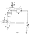
- a shift fork 2 is on a shift rod 4 by means of a shift carriage. 6 guided longitudinally displaceable.
- the shift fork 2 engages in a known manner in one Shift sleeve, the rotationally fixed and arranged longitudinally displaceable on a gear shaft is.
- a control arm 8 is fixed, by a driven by an electric motor 10 spindle 12 is adjustable.
- the adjusting or switching device works in the following way:
- the circuit device 30 of the electric motor 10 is started, wherein the spindle 12th the shift carriage 6 and the shift fork 2 on the shift rod 4 to the left or after is moved to the right. Simultaneously with the starting of the electric motor 10 or alternatively to, after a first operated by the electric motor 10 adjustment, is about the circuit device 30 activates the switching valve 28 and one of the two Pressure chambers 20 and 22 of the hydraulic cylinder 16 supplied hydraulic oil, so that the Piston rod 14 and thus the shift carriage 6 and the shift fork 2, through the electromotive drive supported, is moved to the left or right.
- Fig. 2 is while the switching position of the switching valve 28 for an adjustment of the shift fork 2 after shown on the left, while in Fig. 3, the switching position of the switching valve 28 for a Adjustment of the shift fork 2 is shown to the right.
Landscapes
- Engineering & Computer Science (AREA)
- General Engineering & Computer Science (AREA)
- Mechanical Engineering (AREA)
- Physics & Mathematics (AREA)
- Fluid Mechanics (AREA)
- Gear-Shifting Mechanisms (AREA)
Abstract
Description
- Fig. 1
- einen schematischen Aufbau einer Schalteinrichtung für ein Wechselgetriebe,
- Fig. 2
- eine erste Schaltposition der Schalteinrichtung und
- Fig. 3
- eine zweite Schaltposition der Schalteinrichtung.
Claims (4)
- Schalteinrichtung für ein Wechselgetriebe, insbesondere automatisiertes Schaltgetriebe für ein Kraftfahrzeug, mit einer Schaltstange (4), auf der mindestens eine Schaltgabel (2) längsverschieblich gelagert ist, wobei die Schaltgabel in ein Verbindungsorgan (Schaltmuffe) einer Synchronisiereinheit eingreift, die auf einer Getriebewelle angeordnet ist, und dass zur Verstellung der Schaltgabel (2) ein Hilfskraft betätigbarer Antrieb (16, 10) vorgesehen ist, dadurch gekennzeichnet, dass der Antrieb aus einer kombinierten elektro- hydraulischen Verstelleinrichtung (10, 16) besteht.
- Schalteinrichtung nach Anspruch 1, dadurch gekennzeichnet, dass die Verstelleinrichtung aus einem Elektromotor (10) und einem über ein Schaltventil (28) aktivierbaren Hydraulikzylinder (16) besteht, die beide zur Verstellung der Schaltgabel (2) mit ihren Stellorganen (12, 14) an einem Schaltschlitten (6) der Schaltgabel (2) angreifen.
- Schalteinrichtung nach Anspruch 2, dadurch gekennzeichnet, dass der Elektromotor (10) den Schaltschlitten (6) über eine Spindel (12) antreibt, während der Hydraulikzylinder (16) zwei Druckräume (20, 22) aufweist, die durch einen Stellkolben (18) voneinander getrennt sind.
- Verfahren zum Betreiben einer Schalteinrichtung gemäß den Merkmalen einer der Ansprüche 1 bis 3, dadurch gekennzeichnet, dass nach dem Starten des Elektromotors (10) oder nach einem ersten durch den Elektromotor (10) betriebenen Stellweg über ein Schaltventil (16) der Hydraulikzylinder (16) aktiviert wird.
Applications Claiming Priority (2)
| Application Number | Priority Date | Filing Date | Title |
|---|---|---|---|
| DE200410015756 DE102004015756A1 (de) | 2004-03-31 | 2004-03-31 | Schalteinrichtung für ein Wechselgetriebe sowie Verfahren zum Betreiben einer Schalteinrichtung |
| DE102004015756 | 2004-03-31 |
Publications (3)
| Publication Number | Publication Date |
|---|---|
| EP1582780A2 true EP1582780A2 (de) | 2005-10-05 |
| EP1582780A3 EP1582780A3 (de) | 2007-03-21 |
| EP1582780B1 EP1582780B1 (de) | 2008-12-10 |
Family
ID=34877664
Family Applications (1)
| Application Number | Title | Priority Date | Filing Date |
|---|---|---|---|
| EP20050005074 Expired - Lifetime EP1582780B1 (de) | 2004-03-31 | 2005-03-09 | Schalteinrichtung für ein Wechselgetriebe sowie Verfahren zum Betreiben einer Schalteinrichtung |
Country Status (2)
| Country | Link |
|---|---|
| EP (1) | EP1582780B1 (de) |
| DE (2) | DE102004015756A1 (de) |
Families Citing this family (1)
| Publication number | Priority date | Publication date | Assignee | Title |
|---|---|---|---|---|
| DE102011117486A1 (de) | 2011-10-26 | 2013-05-02 | Getrag Getriebe- Und Zahnradfabrik Hermann Hagenmeyer Gmbh & Cie Kg | Schaltanordnung für ein Kraftfahrzeuggetriebe |
Family Cites Families (5)
| Publication number | Priority date | Publication date | Assignee | Title |
|---|---|---|---|---|
| DE1101177B (de) * | 1958-02-06 | 1961-03-02 | Carl F W Borgward G M B H | Synchronisier- und Schalteinrichtung fuer durch Druckmittel automatisch geschaltete Wechselgetriebe, insbesondere von Kraftfahrzeugen |
| SU1093575A1 (ru) * | 1983-02-08 | 1984-05-23 | Предприятие П/Я Г-4695 | Система автоматического управлени ступенчатой коробкой передач со сдвоенным сцеплением |
| US5205179A (en) * | 1990-07-21 | 1993-04-27 | Ina Walzlager Schaeffler Kg | Speed changing device |
| DE19756637A1 (de) * | 1997-12-19 | 1999-06-24 | Zahnradfabrik Friedrichshafen | Schalteinrichtung |
| FR2789743A1 (fr) * | 1999-02-17 | 2000-08-18 | Mannesmann Sachs Ag | Boite de vitesses automatique |
-
2004
- 2004-03-31 DE DE200410015756 patent/DE102004015756A1/de not_active Withdrawn
-
2005
- 2005-03-09 DE DE200550006180 patent/DE502005006180D1/de not_active Expired - Lifetime
- 2005-03-09 EP EP20050005074 patent/EP1582780B1/de not_active Expired - Lifetime
Non-Patent Citations (1)
| Title |
|---|
| None |
Also Published As
| Publication number | Publication date |
|---|---|
| EP1582780B1 (de) | 2008-12-10 |
| EP1582780A3 (de) | 2007-03-21 |
| DE102004015756A1 (de) | 2005-10-20 |
| DE502005006180D1 (de) | 2009-01-22 |
Similar Documents
| Publication | Publication Date | Title |
|---|---|---|
| DE19961532A1 (de) | Ergonomische elektronische Handsteuerung für einen Motorgrader | |
| DE102010009338A1 (de) | Getriebesteller | |
| DE19635866C2 (de) | Schaltvorrichtung für ein Zahnräderwechselgetriebe | |
| EP1040289B1 (de) | Schalteinrichtung für ein getriebe | |
| EP0180111A2 (de) | Gangschaltautomat | |
| EP1836421B1 (de) | Vorrichtung zur betätigung von schaltgabeln | |
| DE19800880A1 (de) | Schaltvorrichtung für ein mehrgängiges Wechselgetriebe | |
| EP2918877A1 (de) | Schaltanordnung für ein Kraftfahrzeuggetriebe und Schaltverfahren | |
| EP1836419B1 (de) | Schalteinrichtung für ein getriebe und verwendung einer solchen schalteinrichtung | |
| DE3315221C2 (de) | ||
| EP1870617B1 (de) | Betätigungseinrichtung für ein Getriebe eines Fahrzeugs | |
| EP1520127B1 (de) | Getriebeschaltung | |
| EP1291560B1 (de) | Hilfskraftunterstützte Getriebeschaltvorrichtung | |
| EP1582780B1 (de) | Schalteinrichtung für ein Wechselgetriebe sowie Verfahren zum Betreiben einer Schalteinrichtung | |
| DE102006005249A1 (de) | Getriebestellvorrichtung, Schaltgetriebe und Verfahren zur Durchführung einer Schaltbewegung | |
| WO2010089224A1 (de) | Schaltvorrichtung für ein getriebe eines kraftfahrzeugs | |
| EP1917462B1 (de) | Schaltanordnung zum verschieben einer schaltgabel | |
| EP1302706B1 (de) | Schaltgetriebe | |
| DE202005018390U1 (de) | Ventilvorrichtung für eine hydraulische Servolenkung | |
| WO2015149798A1 (de) | Schaltwalzenaktorik mit durch spannungserhöhung dynamikgesteigerter ausführung | |
| WO2009015995A1 (de) | Getriebesteller zum betätigen einer schalteinrichtung eines getriebes | |
| DE102004046730A1 (de) | Schalteinrichtung für ein mehrgängiges Schaltgetriebe | |
| WO2017080720A1 (de) | Anordnung zum betätigen zumindest eines schaltelementes | |
| EP2767740A1 (de) | Schalteinrichtung mit einer Schalt- und Wählwelle für ein Fahrzeuggetriebe | |
| WO2005038309A1 (de) | Schalteinrichtung |
Legal Events
| Date | Code | Title | Description |
|---|---|---|---|
| PUAI | Public reference made under article 153(3) epc to a published international application that has entered the european phase |
Free format text: ORIGINAL CODE: 0009012 |
|
| AK | Designated contracting states |
Kind code of ref document: A2 Designated state(s): AT BE BG CH CY CZ DE DK EE ES FI FR GB GR HU IE IS IT LI LT LU MC NL PL PT RO SE SI SK TR |
|
| AX | Request for extension of the european patent |
Extension state: AL BA HR LV MK YU |
|
| PUAL | Search report despatched |
Free format text: ORIGINAL CODE: 0009013 |
|
| AK | Designated contracting states |
Kind code of ref document: A3 Designated state(s): AT BE BG CH CY CZ DE DK EE ES FI FR GB GR HU IE IS IT LI LT LU MC NL PL PT RO SE SI SK TR |
|
| AX | Request for extension of the european patent |
Extension state: AL BA HR LV MK YU |
|
| RIC1 | Information provided on ipc code assigned before grant |
Ipc: F16H 61/30 20060101ALI20070213BHEP Ipc: F16H 61/32 20060101ALI20070213BHEP Ipc: F16H 61/28 20060101AFI20050720BHEP Ipc: F16H 63/30 20060101ALI20070213BHEP |
|
| 17P | Request for examination filed |
Effective date: 20070921 |
|
| AKX | Designation fees paid |
Designated state(s): DE FR GB IT |
|
| 17Q | First examination report despatched |
Effective date: 20071105 |
|
| RAP1 | Party data changed (applicant data changed or rights of an application transferred) |
Owner name: DR. ING. H.C. F. PORSCHE AKTIENGESELLSCHAFT |
|
| RAP1 | Party data changed (applicant data changed or rights of an application transferred) |
Owner name: DR. ING. H.C. F. PORSCHE AKTIENGESELLSCHAFT |
|
| GRAP | Despatch of communication of intention to grant a patent |
Free format text: ORIGINAL CODE: EPIDOSNIGR1 |
|
| GRAS | Grant fee paid |
Free format text: ORIGINAL CODE: EPIDOSNIGR3 |
|
| GRAA | (expected) grant |
Free format text: ORIGINAL CODE: 0009210 |
|
| AK | Designated contracting states |
Kind code of ref document: B1 Designated state(s): DE FR GB IT |
|
| REG | Reference to a national code |
Ref country code: GB Ref legal event code: FG4D Free format text: NOT ENGLISH |
|
| REF | Corresponds to: |
Ref document number: 502005006180 Country of ref document: DE Date of ref document: 20090122 Kind code of ref document: P |
|
| PLBE | No opposition filed within time limit |
Free format text: ORIGINAL CODE: 0009261 |
|
| STAA | Information on the status of an ep patent application or granted ep patent |
Free format text: STATUS: NO OPPOSITION FILED WITHIN TIME LIMIT |
|
| 26N | No opposition filed |
Effective date: 20090911 |
|
| REG | Reference to a national code |
Ref country code: FR Ref legal event code: TP |
|
| REG | Reference to a national code |
Ref country code: GB Ref legal event code: 732E Free format text: REGISTERED BETWEEN 20110310 AND 20110316 |
|
| REG | Reference to a national code |
Ref country code: GB Ref legal event code: 732E Free format text: REGISTERED BETWEEN 20110331 AND 20110406 |
|
| PGFP | Annual fee paid to national office [announced via postgrant information from national office to epo] |
Ref country code: FR Payment date: 20110404 Year of fee payment: 7 |
|
| PGFP | Annual fee paid to national office [announced via postgrant information from national office to epo] |
Ref country code: GB Payment date: 20110321 Year of fee payment: 7 |
|
| GBPC | Gb: european patent ceased through non-payment of renewal fee |
Effective date: 20120309 |
|
| REG | Reference to a national code |
Ref country code: FR Ref legal event code: ST Effective date: 20121130 |
|
| PG25 | Lapsed in a contracting state [announced via postgrant information from national office to epo] |
Ref country code: GB Free format text: LAPSE BECAUSE OF NON-PAYMENT OF DUE FEES Effective date: 20120309 Ref country code: FR Free format text: LAPSE BECAUSE OF NON-PAYMENT OF DUE FEES Effective date: 20120402 |
|
| PGFP | Annual fee paid to national office [announced via postgrant information from national office to epo] |
Ref country code: IT Payment date: 20190325 Year of fee payment: 15 Ref country code: DE Payment date: 20190304 Year of fee payment: 15 |
|
| REG | Reference to a national code |
Ref country code: DE Ref legal event code: R119 Ref document number: 502005006180 Country of ref document: DE |
|
| PG25 | Lapsed in a contracting state [announced via postgrant information from national office to epo] |
Ref country code: DE Free format text: LAPSE BECAUSE OF NON-PAYMENT OF DUE FEES Effective date: 20201001 |
|
| PG25 | Lapsed in a contracting state [announced via postgrant information from national office to epo] |
Ref country code: IT Free format text: LAPSE BECAUSE OF NON-PAYMENT OF DUE FEES Effective date: 20200309 |