EP1582751B1 - Pump unit - Google Patents
Pump unit Download PDFInfo
- Publication number
- EP1582751B1 EP1582751B1 EP04008040A EP04008040A EP1582751B1 EP 1582751 B1 EP1582751 B1 EP 1582751B1 EP 04008040 A EP04008040 A EP 04008040A EP 04008040 A EP04008040 A EP 04008040A EP 1582751 B1 EP1582751 B1 EP 1582751B1
- Authority
- EP
- European Patent Office
- Prior art keywords
- terminal box
- stator housing
- pump unit
- heat distributor
- heat
- Prior art date
- Legal status (The legal status is an assumption and is not a legal conclusion. Google has not performed a legal analysis and makes no representation as to the accuracy of the status listed.)
- Expired - Lifetime
Links
- 238000001816 cooling Methods 0.000 claims description 26
- 230000002093 peripheral effect Effects 0.000 claims description 20
- 238000009423 ventilation Methods 0.000 claims description 12
- 238000007789 sealing Methods 0.000 claims description 9
- 238000010438 heat treatment Methods 0.000 abstract description 3
- 239000012080 ambient air Substances 0.000 description 9
- 239000003570 air Substances 0.000 description 4
- 239000000654 additive Substances 0.000 description 2
- 230000000295 complement effect Effects 0.000 description 2
- 238000009434 installation Methods 0.000 description 2
- 239000002918 waste heat Substances 0.000 description 2
- 230000001419 dependent effect Effects 0.000 description 1
- 238000011161 development Methods 0.000 description 1
- 230000018109 developmental process Effects 0.000 description 1
- 239000000428 dust Substances 0.000 description 1
- 238000005516 engineering process Methods 0.000 description 1
- 238000002347 injection Methods 0.000 description 1
- 239000007924 injection Substances 0.000 description 1
- 229910052500 inorganic mineral Inorganic materials 0.000 description 1
- 238000004519 manufacturing process Methods 0.000 description 1
- 239000007769 metal material Substances 0.000 description 1
- 239000011707 mineral Substances 0.000 description 1
- 238000012806 monitoring device Methods 0.000 description 1
- 238000013021 overheating Methods 0.000 description 1
- 230000000149 penetrating effect Effects 0.000 description 1
- 230000035515 penetration Effects 0.000 description 1
Images
Classifications
-
- F—MECHANICAL ENGINEERING; LIGHTING; HEATING; WEAPONS; BLASTING
- F04—POSITIVE - DISPLACEMENT MACHINES FOR LIQUIDS; PUMPS FOR LIQUIDS OR ELASTIC FLUIDS
- F04D—NON-POSITIVE-DISPLACEMENT PUMPS
- F04D13/00—Pumping installations or systems
- F04D13/02—Units comprising pumps and their driving means
- F04D13/06—Units comprising pumps and their driving means the pump being electrically driven
- F04D13/0686—Mechanical details of the pump control unit
-
- F—MECHANICAL ENGINEERING; LIGHTING; HEATING; WEAPONS; BLASTING
- F04—POSITIVE - DISPLACEMENT MACHINES FOR LIQUIDS; PUMPS FOR LIQUIDS OR ELASTIC FLUIDS
- F04D—NON-POSITIVE-DISPLACEMENT PUMPS
- F04D29/00—Details, component parts, or accessories
- F04D29/58—Cooling; Heating; Diminishing heat transfer
- F04D29/5813—Cooling the control unit
-
- H—ELECTRICITY
- H02—GENERATION; CONVERSION OR DISTRIBUTION OF ELECTRIC POWER
- H02K—DYNAMO-ELECTRIC MACHINES
- H02K11/00—Structural association of dynamo-electric machines with electric components or with devices for shielding, monitoring or protection
- H02K11/30—Structural association with control circuits or drive circuits
- H02K11/33—Drive circuits, e.g. power electronics
-
- H—ELECTRICITY
- H02—GENERATION; CONVERSION OR DISTRIBUTION OF ELECTRIC POWER
- H02K—DYNAMO-ELECTRIC MACHINES
- H02K5/00—Casings; Enclosures; Supports
- H02K5/04—Casings or enclosures characterised by the shape, form or construction thereof
- H02K5/06—Cast metal casings
-
- H—ELECTRICITY
- H02—GENERATION; CONVERSION OR DISTRIBUTION OF ELECTRIC POWER
- H02K—DYNAMO-ELECTRIC MACHINES
- H02K5/00—Casings; Enclosures; Supports
- H02K5/04—Casings or enclosures characterised by the shape, form or construction thereof
- H02K5/22—Auxiliary parts of casings not covered by groups H02K5/06-H02K5/20, e.g. shaped to form connection boxes or terminal boxes
- H02K5/225—Terminal boxes or connection arrangements
Definitions
- the invention relates to a pump unit, in particular a heating circulation pump, having the features specified in the preamble of claim 1.
- Such electrically operated pump units usually have terminal boxes that connect the pump units to a power supply and their power and control electronics and controls include.
- the terminal boxes are usually arranged shell-shaped on the outer lateral surfaces of the motor housing of the pump units.
- the terminal boxes have heat sinks or heat exchangers which release the waste heat of the electronic components through the housing wall into the ambient air.
- EP-A-0 854 560 describes an electric drive system with an electric motor and arranged on a front side of the motor housing, in which a converter and the drive electronics of the motor are arranged. At the side facing away from the motor of the housing, a housing part adjoins, in which a fan driven by a separate fan motor and a heat exchanger are arranged for cooling the electronic components.
- a motor-driven fan requires a great deal of design and control engineering effort and leads to a relatively large range of the motor in the direction of the stator.
- the present invention seeks to provide a compact pump unit, in which the waste heat of the power and control electronics can be sufficiently dissipated and the production of the pump unit can be realized in a simple manner.
- the pump unit has a stator housing and a terminal box attached to the outside of the stator housing. At least a first area of the terminal box covers an end face of the stator housing. In this area of the terminal box, a heat spreader for cooling electronic components is arranged. At least a second area of the terminal box is arranged on a peripheral portion of the stator housing.
- the power supply of the pump unit and components of the power and control electronics are arranged in the terminal box, for example. Among them are electronic components that develop such a large amount of self-heat that they have to be removed from the terminal box.
- the terminal box is attached to the stator housing of an electric drive motor of the pump unit. At least a first region of the terminal box covers the front side of the stator housing. At least a second area of the terminal box is arranged on a peripheral portion of the stator housing.
- the terminal box expediently has complementary connecting elements to these terminals, which produce a direct electrical connection of the drive motor with the power supply and the power and control electronics.
- the connecting elements are preferably formed on a circuit board on which at least parts of the power and control electronics of the pump unit are arranged and which is arranged in the terminal box advantageously in a plane parallel to the end face of the stator housing.
- a heat spreader is arranged in the region of the terminal box, which covers the end face of the stator housing, through which the heat is discharged from the terminal box to the ambient air.
- the arrangement of the heat spreader on the end face of the stator housing makes it possible to provide a large heat delivery surface, which is easily accessible from all sides, so that a sufficient cooling air supply is ensured in each installation position of the pump.
- the shape of the heat spreader is advantageously adapted to the end face of the stator housing.
- at least one base surface of the heat spreader extends over a surface which, in terms of its dimensions and shape, substantially corresponds to the entire surface of the end face of the stator housing.
- the heat spreader can be made so large that it can dissipate the heat of heat-generating electronic components sufficiently.
- the size of the heat spreader allows the use of non-metallic materials, eg. B. plastic optionally with the thermal conductivity improving additives.
- the heat spreader is disposed completely inside the terminal box.
- the housing wall of the terminal box covers the area of the end face of the stator housing so that the heat distributor arranged there is completely surrounded by the terminal box. Users of the pump set are thus protected from any contact with the hot heat spreader.
- Ventilation openings are formed in an outer wall of the terminal box in the vicinity of the heat spreader.
- the ventilation openings are expediently designed so large that it can be dissipated by them the largest possible heat flow from the interior of the terminal box, on the other hand accidental contact of a person with the located in the terminal box heat spreader is prevented.
- the ventilation openings are formed in an outer wall of the terminal box circumferentially surrounding the heat distributor, preferably distributed over the entire circumference, while an outer wall of the terminal box covering the heat distributor on its side facing away from the stator housing is designed to be closed.
- the ventilation openings may be slit-shaped or openings may be arranged so that they form a grid-like structure. If very large heat flows have to be dissipated, at least a portion of the outer wall of the terminal box, which covers the heat distributor on its side facing away from the stator housing, can also have ventilation openings.
- the distribution of the ventilation openings over the entire circumference has the advantage cooling air can flow from all sides through the area of the terminal box in which the heat spreader is located. Thus, in each installation position of the pump sufficient air circulation for cooling the heat spreader is possible.
- the terminal box has a second area, which is arranged on a peripheral portion of the stator housing.
- This region of the terminal box is preferably bounded by a circumferential surface of the stator housing spaced lateral surface and two extending in the radial direction of the stator housing end faces on the pump side and the heat exchanger end of the lateral surface to the outside and provides a further space for electronic components.
- the second region of the terminal box is at least partially integral with the first region of the terminal box, for example formed as a plastic injection-molded rope.
- the self-heat generating components can optionally via an additional heat exchanger, which can be arranged on an inner wall of the terminal box in this area, preferably on the lateral surface, are cooled.
- an additional heat exchanger which can be arranged on an inner wall of the terminal box in this area, preferably on the lateral surface, are cooled.
- operating and / or display elements are arranged on an end face of the stator housing facing away from the end face of the second region of the terminal box.
- the operating and display elements are thus located on the heat exchanger side end face of the second region of the terminal box, ie on the pump facing away with the pipe connections free end face so that they are very accessible to a person standing in front of the pump unit.
- the end face, on which the operating and / or display elements are arranged, is preferably offset from the outer wall of the terminal box, which covers the heat distributor on its side facing away from the stator housing, in the direction of the stator housing. This ensures that the outer wall surrounding the heat exchanger circumferentially of the terminal box and thus arranged on this outer wall ventilation openings are completely exposed and so the heat exchange of the heat spreader with the ambient air in all radial directions is not hindered.
- the heat spreader advantageously has a plurality of cooling ribs and / or cooling pins, which preferably extend on the side of the heat distributor facing away from the front side of the stator housing normal to the end side of the stator housing.
- the heat exchange surface of the heat spreader can be significantly increased compared to a newly formed heat spreader so that correspondingly larger heat flows can be discharged from the heat spreader to the ambient air.
- the cooling fins and / or cooling pins are preferably arranged such that between you in each diameter direction of the heat spreader flow paths for cooling air are formed.
- the cooling fins and cooling pins can be arranged on a base of the heat spreader so that they form rows that extend in a star shape outward from the center of the base.
- ambient air can flow through the heat spreader in all directions radially to the stator axis.
- cooling pins are particularly preferred to arrange cooling pins on the base of the heat spreader so that they spaced apart, preferably evenly distributed over the base of the heat spreader. In this way, each cooling pin is completely surrounded by sufficiently large flow paths, so that it can be flowed from all directions radially to the stator axis and can emit its heat load to the ambient air.
- a sealing element is arranged between the peripheral region of the heat distributor and an adjacent wall of the terminal box.
- the area of the terminal box which is located behind the heat spreader and which contains the electronics of the pump set, is sealed off from the area of the terminal box formed by the heat spreader and the housing area of the terminal box covering the heat spreader.
- the sealing element prevents the penetration of moisture into the region of the terminal box in which the power and control electronics are arranged. In this way, the electrical or electronic equipment of the terminal box is protected from moisture.
- the heat spreader is made of plastic and is advantageously designed as an injection molded part. In this way, the heat spreader can be easily and inexpensively manufactured. Because of the low weight of the plastic, the heat spreader can be easily mounted in the terminal box. To improve the thermal conductivity, the plastic can be added, for example, mineral additives.
- stator housing 2 of a drive motor of a pump unit and arranged on this stator housing 2 terminal box consisting of a first terminal box part 4 and a second terminal box part 6.
- the stator housing 2 is provided with a surface 3 to a pump not shown in the drawings flanged
- the first terminal box part 4 is a one-piece plastic injection-molded part and consists of a hollow circular cylindrical portion 8 and a peripherally connected to the outer wall portion 10, which has the shape of a hollow cylindrical ring segment and the pump-side end face region 12 is closed by an outer wall.
- the two areas 8 and 10 of the first terminal box part 4 are connected to one another in such a way that together they form an open end face of the first terminal box part 4 facing away from the pump.
- This has the shape of two approximately semicircular circular sections with different diameters, which are connected to each other at their cutting edges, wherein the circular sections are concentric with each other.
- the length of the cylindrical annular region 10 in the direction of the stator longitudinal axis is greater than the length of the circular cylindrical region 8 of the terminal box 4, so that the region 10 with respect to the area 8 in the direction of the pump, a projection 11 is formed.
- the first terminal box part 4 is fixed to the stator housing 2 so that the stator housing 2 facing outer wall of the projection 11 of the area 10 abuts the peripheral surface of the stator housing 2 and the outer wall of the area 8 covers a portion of the peripheral surface and an end face 14 of the stator housing 2 ie the stator housing 2 engages in the circular-cylindrical or cup-shaped region 8 of the terminal box 4.
- the inner diameter of the region 8 corresponds to the outer diameter of the stator housing 2.
- a board 16 is fitted in a spaced apart from the end face 14 parallel plane in the terminal box part 4, the board 16 a complementary to the end face or the inner cross section of the terminal box part 4 Having outer contour.
- At least part of a power and control electronics of the pump unit is mounted on the circuit board 16, in particular on the side of the circuit board 16 facing the stator housing 2.
- connection sockets 20 of the board 16 plug contacts 18 are arranged at the end face 14 of the stator housing 2 at the end face 14 of the stator housing 2 . These plug contacts 18 are distributed in the vicinity of the peripheral surface of the stator housing 2 around the circumference of the end face 14.
- the circuit board 16 has on its side facing the stator housing 2 connecting sockets 20 whose orientation corresponds to the positions of the plug contacts 18 on the end face 14 of the stator housing 2, so that the plug contacts 18 of the stator housing 2 in the assembled state in the connection sockets 20 of the board 16 engage ,
- the engaging in the connection sockets 20 of the board 16 plug contacts 18 provide an electrical connection between the drive motor of the pump set and a power supply and the power and control electronics ago, which are arranged on the circuit board 16.
- a flat contact surface 22 of a heat-generating component 24 is arranged on the circuit board 16 within the circular-cylindrical region 8 of the first terminal box part 4.
- a heat spreader 26 On this contact surface 22 is in the assembled state of the terminal box, a heat spreader 26 with a flat base plate 28.
- the base plate 28 of the heat spreader 26 is circular and has a diameter which is adapted to the inner diameter of the circular cylindrical portion 8 of the first terminal box part 4.
- a plurality of cooling pins 30 are arranged, which is evenly distributed over the base plate 28 each in a direction normal to this, i. parallel to the stator longitudinal axis, extend.
- the heat spreader 26 is enveloped by the second terminal box part 6.
- the second terminal box part 6 forms the cover of the first terminal box part 4. Accordingly, the second terminal box part 6 circumferentially the same outer contour as the first terminal box part 4.
- the second terminal box part 6 has a circular cylindrical base body 32, which corresponds to the circular cylindrical portion 8 of the first terminal box part 4 and a outside of the main body 32 arranged cylinder ring segment 34 whose outer contour of the outer contour of the region 10 of the first terminal box part 4 is adjusted.
- the cylinder ring segment 34 is arranged on the base body 32 or integrally formed therewith, that the base body 32 and the cylinder ring segment 34 statorally form a common open end face of the second terminal box part 6.
- the peripheral edge 33 of this open end face is in the closed state of the terminal box at the peripheral edge 35 of the first terminal box part 4 in the region of the board 16, wherein the contact area between the first and second terminal box part is sealed by a sealing element, not shown, or sealing means.
- the longitudinal extent of the cylinder ring segment 34 of the second terminal box part 6 is smaller than that of the cylindrical base body 32 of the second terminal box part 6. In this way, the base body 32 projects prominently with respect to the cylinder ring segment 34 in a direction away from the stator housing 2, so that the main body 32 is circumferentially one having complete peripheral wall.
- the main body 32 of the second terminal box part 6 has at its end facing away from the stator housing 2 a closed end face 38, whereas on its circular cylindrical peripheral surface, which protrudes relative to the cylinder ring segment 34 in the direction of the stator longitudinal axis distributed over the entire circumference ventilation slots 36 are arranged. These vents 36 allow the cooling pins 30 of the heat spreader 26 to be flowed or circulated by ambient air from all radial directions.
- the cylinder ring segment 34 of the first terminal box part 4 has a stator housing 2 facing away from the closed end face 39, which is interrupted by a recess 40. In the area of this recess 40, operating and display elements, not shown, of the terminal box are arranged in FIGS. 1 and 2 and connected to the electronics mounted on the board 16.
- the circular cylindrical base body 32 of the second terminal box part 6 is sealed relative to the heat spreader 26.
- the sealing takes place via a not shown in FIGS. 1 and 2 sealing element, preferably by a sealing ring between a peripheral edge 42 of the base plate 28 of the heat spreader 26 and a peripheral edge 44 in the region of the stator housing 2 facing end face of the cylindrical base body 32 of the second Terminal box part 6 is arranged.
- the circular or annular sealing or contact surface between heat spreader 26 and second terminal box part 6 allows a reliable seal this connection line.
- the above-described design of the terminal box whose largely cylindrical housing forms an axial extension of the stator housing 2, provides a simple electrical connection of the stator, space for a large heat spreader 26, which can sufficiently dissipate the heat generated during operation within the terminal box , and last but not least an attractive form of the entire pump set.
Landscapes
- Engineering & Computer Science (AREA)
- Power Engineering (AREA)
- Mechanical Engineering (AREA)
- General Engineering & Computer Science (AREA)
- Microelectronics & Electronic Packaging (AREA)
- Physics & Mathematics (AREA)
- Thermal Sciences (AREA)
- Eye Examination Apparatus (AREA)
- Structures Of Non-Positive Displacement Pumps (AREA)
- Non-Positive Displacement Air Blowers (AREA)
- Motor Or Generator Cooling System (AREA)
Abstract
Description
Die Erfindung betrifft ein Pumpenaggregat, insbesondere eine Heizungsumwälzpumpe, mit den im Oberbegriff des Anspruchs 1 angegebenen Merkmalen.The invention relates to a pump unit, in particular a heating circulation pump, having the features specified in the preamble of claim 1.
Derartige elektrisch betriebene Pumpenaggregate weisen üblicherweise Klemmenkästen auf, die die Pumpenaggregate mit einer Stromversorgung verbinden und deren Leistungs- und Steuerungselektronik sowie Bedienelemente beinhalten. Die Klemmenkästen sind zumeist schalenförmig an den äußeren Mantelflächen der Motorgehäuse der Pumpenaggregate angeordnet.Such electrically operated pump units usually have terminal boxes that connect the pump units to a power supply and their power and control electronics and controls include. The terminal boxes are usually arranged shell-shaped on the outer lateral surfaces of the motor housing of the pump units.
Da sich einige elektronische Bauteile während des Pumpenbetriebs sehr stark erwärmen, weisen die Klemmenkästen Kühlkörper bzw. Wärmetauscher auf, die die Abwärme der elektronischen Bauteile durch die Gehäusewand an die Umgebungsluft abgeben.Since some electronic components heat up very much during pump operation, the terminal boxes have heat sinks or heat exchangers which release the waste heat of the electronic components through the housing wall into the ambient air.
Mit immer intelligenter werdenden Kontroll- und Steuerungseinrichtungen der Pumpenaggregate, wie sie beispielsweise in der Heiztechnik eingesetzt werden, nimmt auch der Umfang deren elektronischer Ausstattung stetig zu. Entsprechend vergrößert sich in den Klemmenkästen die Anzahl derjeniger Bauteile der Leistungs- und Steuerungselektronik, die während des Betriebs eine so große Eigenwärme erzeugen, dass diese von Wärmetauschern abgeführt werden muss. Bekannte Pumpenaggregate stoßen hier bezüglich der Abfuhr der von der Elektronik erzeugten Wärme an ihre Grenzen.With increasingly intelligent control and monitoring devices of the pump units, as used for example in heating technology, the extent of their electronic equipment is steadily increasing. Correspondingly, the number of those components of the power and control electronics which generate so much self-heat during operation that they must be dissipated by heat exchangers increases in the terminal boxes. Known pump units come here with respect to the removal of the heat generated by the electronics to their limits.
Bei der Anordnung wärmeerzeugender elektronischer Bauteile ist eine effiziente Kühlung häufig nicht nur erforderlich, um diese Bauteile selber vor Überhitzung zu schützen sondern auch, um mögliche benachbarte wärmeempfindliche Bauteile zu schützen.In providing heat-producing electronic components, efficient cooling is often required not only to protect these components themselves from overheating, but also to protect any adjacent heat-sensitive components.
Vor diesem Hintergrund liegt der vorliegenden Erfindung die Aufgabe zugrunde, ein kompaktes Pumpenaggregat zu schaffen, bei dem die Abwärme der Leistungs- und Steuerungselektronik in ausreichendem Maße abgeführt werden kann und die Herstellung des Pumpenaggregats in einfacher Weise realisiert werden kann.Against this background, the present invention seeks to provide a compact pump unit, in which the waste heat of the power and control electronics can be sufficiently dissipated and the production of the pump unit can be realized in a simple manner.
Diese Aufgabe wird erfindungsgemäß durch ein Pumpenaggregat mit den im Anspruch 1 angegebenen Merkmalen gelöst. Vorteilhafte Weiterbildungen der Erfindung ergeben sich aus den Unteransprüchen, der nachfolgenden Beschreibung und der Zeichnung.This object is achieved by a pump unit having the features specified in claim 1. Advantageous developments of the invention will become apparent from the dependent claims, the following description and the drawings.
Das Pumpenaggregat weist ein Statorgehäuse und einen an der Außenseite des Statorgehäuses angebrachten Klemmenkasten auf. Dabei überdeckt zumindest ein erster Bereich des Klemmenkastens eine Stirnseite des Statorgehäuses. In diesem Bereich des Klemmenkastens ist ein Wärmeverteiler zur Kühlung elektronischer Bauelemente angeordnet. Zumindest ein zweiter Bereich des Klemmenkastens ist an einem Umfangsabschnitt des Statorgehäuses angeordnet. Neben Bedienelementen, die in dem Klemmenkasten zweckmäßigerweise so angebracht sind, dass sie an der Außenwand des Klemmenkastens frei zugänglich sind, sind in dem Klemmenkasten beispielsweise die Stromversorgung des Pumpenaggregats sowie Bauteile der Leistungs- und Steuerungselektronik angeordnet. Darunter befinden sich elektronische Bauteile, die strombeaufschlagt eine so große Eigenwärme entwickeln, dass diese aus dem Klemmenkasten abgeführt werden muss.The pump unit has a stator housing and a terminal box attached to the outside of the stator housing. At least a first area of the terminal box covers an end face of the stator housing. In this area of the terminal box, a heat spreader for cooling electronic components is arranged. At least a second area of the terminal box is arranged on a peripheral portion of the stator housing. In addition to controls that are conveniently mounted in the terminal box so that they are freely accessible on the outer wall of the terminal box, the power supply of the pump unit and components of the power and control electronics are arranged in the terminal box, for example. Among them are electronic components that develop such a large amount of self-heat that they have to be removed from the terminal box.
Der Klemmenkasten ist an dem Statorgehäuse eines elektrischen Antriebsmotors des Pumpenaggregats befestigt. Zumindest ein erster Bereich des Klemmenkastens überdeckt dabei die Stirnseite des Statorgehäuses. Zumindest ein zweiter Bereich des Klemmenkastens ist an einem Umfangsabschnitt des Statorgehäuses angeordnet.The terminal box is attached to the stator housing of an electric drive motor of the pump unit. At least a first region of the terminal box covers the front side of the stator housing. At least a second area of the terminal box is arranged on a peripheral portion of the stator housing.
An der Stirnfläche des Statorgehäuses sind bevorzugt elektrische Anschlüsse des Antriebsmotors angeordnet. Daher weist der Klemmenkasten zweckmäßig in dem die Stirnfläche des Statorgehäuses überdeckenden Bereich zu diesen Anschlüssen komplementäre Verbindungselemente auf, die eine direkte elektrische Verbindung des Antriebsmotors mit der Stromversorgung sowie der Leistungs- und Steuerungselektronik herstellen. Die Verbindungselemente sind vorzugsweise an einer Schaltplatine ausgebildet, auf der zumindest Teile der Leistungs- und Steuerungselektronik des Pumpenaggregats angeordnet sind und die in dem Klemmenkasten vorteilhafterweise in einer Ebene parallel zur Stirnfläche des Statorgehäuses angeordnet ist.On the end face of the stator housing electrical connections of the drive motor are preferably arranged. Therefore, in the area covering the end face of the stator housing, the terminal box expediently has complementary connecting elements to these terminals, which produce a direct electrical connection of the drive motor with the power supply and the power and control electronics. The connecting elements are preferably formed on a circuit board on which at least parts of the power and control electronics of the pump unit are arranged and which is arranged in the terminal box advantageously in a plane parallel to the end face of the stator housing.
Um die Eigenwärme der auf dieser Schaltplatine befindlichen wärmeerzeugenden Bauteile abführen zu können, ist in dem Bereich des Klemmenkastens, welcher die Stirnfläche des Statorgehäuses überdeckt, ein Wärmeverteiler angeordnet, über den die Wärme aus dem Klemmenkasten heraus an die Umgebungsluft abgeleitet wird. Die Anordnung des Wärmeverteilers an der Stirnfläche des Statorgehäuses ermöglicht, eine große Wärmeabgabefläche bereitzustellen, welche von allen Seiten gut zugänglich ist, so dass eine ausreichende Kühlluftzufuhr in jeder Einbaulage der Pumpe gewährleistet ist.In order to dissipate the heat of the heat generating components located on this circuit board, a heat spreader is arranged in the region of the terminal box, which covers the end face of the stator housing, through which the heat is discharged from the terminal box to the ambient air. The arrangement of the heat spreader on the end face of the stator housing makes it possible to provide a large heat delivery surface, which is easily accessible from all sides, so that a sufficient cooling air supply is ensured in each installation position of the pump.
Die Form des Wärmeverteilers ist vorteilhaft der Stirnseite des Statorgehäuses angepasst. So erstreckt sich zumindest eine Grundfläche des Wärmeverteilers über eine Fläche, die hinsichtlich ihrer Abmessungen und Gestalt im Wesentlichen der gesamten Fläche der Stirnseite des Statorgehäuses entspricht. Auf diese Weise kann der Wärmeverteiler so groß ausgebildet werden, dass er die Eigenwärme wärmeerzeugender elektronischer Bauteile in ausreichendem Maße ableiten kann. Die Größe des Wärmeverteilers ermöglicht die Verwendung von nicht metallischen Werkstoffen, z. B. Kunststoff gegebenenfalls mit die Wärmeleitfähigkeit verbessernden Zusätzen.The shape of the heat spreader is advantageously adapted to the end face of the stator housing. Thus, at least one base surface of the heat spreader extends over a surface which, in terms of its dimensions and shape, substantially corresponds to the entire surface of the end face of the stator housing. In this way, the heat spreader can be made so large that it can dissipate the heat of heat-generating electronic components sufficiently. The size of the heat spreader allows the use of non-metallic materials, eg. B. plastic optionally with the thermal conductivity improving additives.
Zweckmäßigerweise ist der Wärmeverteiler vollständig im Inneren des Klemmenkastens angeordnet. Die Gehäusewandung des Klemmenkastens überdeckt den Bereich der Stirnfläche des Statorgehäuses so, dass der dort angeordnete Wärmeverteiler völlig von dem Klemmenkasten umgeben ist. Benutzer des Pumpenaggregats werden so vor eventuellen Kontakten mit dem heißen Wärmeverteiler geschützt.Conveniently, the heat spreader is disposed completely inside the terminal box. The housing wall of the terminal box covers the area of the end face of the stator housing so that the heat distributor arranged there is completely surrounded by the terminal box. Users of the pump set are thus protected from any contact with the hot heat spreader.
Um die von dem Wärmeverteiler aufgenommene Wärme besonders effektiv an die Umgebungsluft weiterleiten zu können, d. h. große Wärmeströme an die Umgebung abgeben zu können, ist es von Vorteil, wenn in einer Außenwandung des Klemmenkastens in der Nähe des Wärmeverteilers Lüftungsöffnungen ausgebildet sind. Dabei sind die Lüftungsöffnungen zweckmäßigerweise so groß gestaltet, dass durch sie ein möglichst großer Wärmestrom aus dem Inneren des Klemmenkastens abgeführt werden kann, andererseits aber ein versehentlicher Kontakt einer Person mit dem in dem Klemmenkasten befindlichen Wärmeverteiler verhindert wird.To be able to forward the heat absorbed by the heat spreader particularly effectively to the ambient air, d. H. To be able to deliver large heat flows to the environment, it is advantageous if ventilation openings are formed in an outer wall of the terminal box in the vicinity of the heat spreader. The ventilation openings are expediently designed so large that it can be dissipated by them the largest possible heat flow from the interior of the terminal box, on the other hand accidental contact of a person with the located in the terminal box heat spreader is prevented.
In einer bevorzugten Ausführungsform sind die Lüftungsöffnungen in einer den Wärmeverteiler umfänglich umgebenden Außenwandung des Klemmenkastens, vorzugsweise über den gesamten Umfang verteilt, ausgebildet, während eine den Wärmeverteiler an seiner dem Statorgehäuse abgewandten Seite überdeckende Außenwandung des Klemmenkastens geschlossen ausgebildet ist. Beispielsweise können die Lüftungsöffnungen schlitzförmig ausgebildet sein oder es können Durchbrechungen so angeordnet sein, dass sie eine gitternetzartige Struktur bilden. Müssen sehr große Wärmeströme abgeleitet werden, kann auch zumindest ein Teilbereich der Außenwandung des Klemmenkastens, die den Wärmeverteiler an seiner dem Statorgehäuse abgewanden Seite überdeckt, Lüftungsöffnungen aufweisen. Die Verteilung der Lüftungsöffnungen über den gesamten Umfang hat den Vorteil, dass Kühlluft von allen Seiten durch den Bereich des Klemmenkastens, in dem der Wärmeverteiler angeordnet ist, strömen kann. So wird in jeder Einbaulage der Pumpe eine ausreichende Luftzirkulation zur Kühlung des Wärmeverteilers ermöglicht.In a preferred embodiment, the ventilation openings are formed in an outer wall of the terminal box circumferentially surrounding the heat distributor, preferably distributed over the entire circumference, while an outer wall of the terminal box covering the heat distributor on its side facing away from the stator housing is designed to be closed. For example, the ventilation openings may be slit-shaped or openings may be arranged so that they form a grid-like structure. If very large heat flows have to be dissipated, at least a portion of the outer wall of the terminal box, which covers the heat distributor on its side facing away from the stator housing, can also have ventilation openings. The distribution of the ventilation openings over the entire circumference has the advantage cooling air can flow from all sides through the area of the terminal box in which the heat spreader is located. Thus, in each installation position of the pump sufficient air circulation for cooling the heat spreader is possible.
Erfindungsgemäß weist der Klemmenkasten einen zweiten Bereich auf, der an einem Umfangsabschnitt des Statorgehäuses angeordnet ist. Dieser Bereich des Klemmenkastens wird vorzugsweise durch eine von der Umfangsfläche des Statorgehäuses beabstandeten Mantelfläche sowie zwei in radialer Richtung des Statorgehäuses verlaufende Stirnflächen am pumpenseitigen und am wärmetauscherseitigen Ende der Mantelfläche nach außen begrenzt und bietet einen weiteren Bauraum für elektronische Komponenten. Bevorzugt ist der zweite Bereich des Klemmenkastens zumindest teilweise einstückig mit dem ersten Bereich des Klemmenkastens, beispielsweise als Kunststoff-Spritzgusseil ausgebildet. Im zweiten Bereich des Klemmenkastens befindliche eigenwärmeerzeugende Bauteile können ggf. über einen zusätzlichen Wärmetauscher, der an einer Innenwandung des Klemmenkastens in diesem Bereich, bevorzugt an dessen Mantelfläche, angeordnet sein kann, gekühlt werden. Die Anordnung eines Teils des Klemmenkastens im Umfangsbereich des Statorgehäuses ermöglicht, die Baulänge des Pumpenaggregats klein zu halten.According to the invention, the terminal box has a second area, which is arranged on a peripheral portion of the stator housing. This region of the terminal box is preferably bounded by a circumferential surface of the stator housing spaced lateral surface and two extending in the radial direction of the stator housing end faces on the pump side and the heat exchanger end of the lateral surface to the outside and provides a further space for electronic components. Preferably, the second region of the terminal box is at least partially integral with the first region of the terminal box, for example formed as a plastic injection-molded rope. In the second region of the terminal box located self-heat generating components can optionally via an additional heat exchanger, which can be arranged on an inner wall of the terminal box in this area, preferably on the lateral surface, are cooled. The arrangement of a part of the terminal box in the peripheral region of the stator housing makes it possible to keep the overall length of the pump unit small.
Zweckmäßigerweise sind an einer der Stirnfläche des Statorgehäuses abgewandten Stirnfläche des zweiten Bereichs des Klemmenkastens Bedien- und/oder Anzeigeelemente angeordnet. Die Bedien- und Anzeigeelemente befinden sich somit an der wärmetauscherseitigen Stirnfläche des zweiten Bereichs des Klemmenkastens, d.h. an der der Pumpe mit den Rohranschlüssen abgewandten freien Stirnfläche, so dass sie für eine vor dem Pumpenaggregat stehende Person sehr gut zugänglich sind.Conveniently, operating and / or display elements are arranged on an end face of the stator housing facing away from the end face of the second region of the terminal box. The operating and display elements are thus located on the heat exchanger side end face of the second region of the terminal box, ie on the pump facing away with the pipe connections free end face so that they are very accessible to a person standing in front of the pump unit.
Die Stirnfläche, an welcher die Bedien- und/oder Anzeigeelemente angeordnet sind, ist bevorzugt gegenüber der Außenwandung des Klemmenkastens, welche den Wärmeverteiler an seiner dem Statorgehäuse abgewandten Seite überdeckt, in Richtung des Statorgehäuses zurückversetzt. Hierdurch ist sichergestellt, dass die den Wärmetauscher umfänglich umgebende Außenwandung des Klemmenkastens und damit die an dieser Außenwandung angeordneten Lüftungsöffnungen vollständig frei liegen und so der Wärmeaustausch des Wärmeverteilers mit der Umgebungsluft in alle radialen Richtungen nicht behindert wird.The end face, on which the operating and / or display elements are arranged, is preferably offset from the outer wall of the terminal box, which covers the heat distributor on its side facing away from the stator housing, in the direction of the stator housing. This ensures that the outer wall surrounding the heat exchanger circumferentially of the terminal box and thus arranged on this outer wall ventilation openings are completely exposed and so the heat exchange of the heat spreader with the ambient air in all radial directions is not hindered.
Der Wärmeverteiler weist vorteilhaft eine Vielzahl von Kühlrippen und/oder Kühlstiften auf, welche sich an der der Stirnseite des Statorgehäuses abgewandten Seite des Wärmeverteilers vorzugsweise normal zur Stirnseite des Statorgehäuses erstrecken. Je nach Anzahl und geometrischer Ausbildung dieser Kühlrippen bzw. Kühlstifte kann die Wärmeaustauschfläche des Wärmeverteilers gegenüber der eines eben ausgebildeten Wärmeverteilers erheblich vergrößert werden, so dass entsprechend größere Wärmeströme von dem Wärmeverteiler an die Umgebungsluft abgegeben werden können.The heat spreader advantageously has a plurality of cooling ribs and / or cooling pins, which preferably extend on the side of the heat distributor facing away from the front side of the stator housing normal to the end side of the stator housing. Depending on the number and geometric design of these cooling fins or cooling pins, the heat exchange surface of the heat spreader can be significantly increased compared to a newly formed heat spreader so that correspondingly larger heat flows can be discharged from the heat spreader to the ambient air.
Da die Leistungsfähigkeit des Wärmeverteilers neben der Größe der Wärmeaustauschflächen auch von der Anströmung durch den Wärmetauschpartner, d. h. in diesem Fall der Umgebungsluft abhängig ist, sind die Kühlrippen und/oder die Kühlstifte vorzugsweise derart angeordnet, dass zwischen Ihnen in jeder Durchmesserrichtung des Wärmeverteilers Strömungswege für Kühlluft ausgebildet sind. So können die Kühlrippen und Kühlstifte beispielsweise auf einer Grundfläche des Wärmeverteilers so angeordnet sein, dass sie Aneinanderreihungen bilden, die vom Mittelpunkt der Grundfläche ausgehend sternförmig nach außen verlaufen. So kann Umgebungsluft den Wärmeverteiler in allen Richtungen radial zur Statorachse durchströmen. Besonders bevorzugt ist es, Kühlstifte so auf der Grundfläche des Wärmeverteilers anzuordnen, dass sie voneinander beabstandet, vorzugsweise gleichmäßig über die Grundfläche des Wärmeverteilers verteilt sind. Auf diese Weise ist jeder Kühlstift vollständig von ausreichend großen Strömungswegen umgeben, so dass er aus allen Richtungen radial zur Statorachse angeströmt werden kann und seine Wärmebeladung an die Umgebungsluft abgeben kann.Since the performance of the heat spreader in addition to the size of the heat exchange surfaces and the flow through the heat exchange partner, ie the ambient air depends in this case, the cooling fins and / or cooling pins are preferably arranged such that between you in each diameter direction of the heat spreader flow paths for cooling air are formed. For example, the cooling fins and cooling pins can be arranged on a base of the heat spreader so that they form rows that extend in a star shape outward from the center of the base. Thus, ambient air can flow through the heat spreader in all directions radially to the stator axis. It is particularly preferred to arrange cooling pins on the base of the heat spreader so that they spaced apart, preferably evenly distributed over the base of the heat spreader. In this way, each cooling pin is completely surrounded by sufficiently large flow paths, so that it can be flowed from all directions radially to the stator axis and can emit its heat load to the ambient air.
Vorteilhaft ist zwischen dem Umfangsbereich des Wärmeverteilers und einer angrenzenden Wandung des Klemmenkastens ein Dichtelement angeordnet. Auf diese Weise wird der statorseitig hinter dem Wärmeverteiler liegende Bereich des Klemmenkastens, der die Elektronik des Pumpenaggregats beinhaltet gegenüber dem Bereich des Klemmenkastens, der durch den Wärmeverteiler und den Gehäusebereich des Klemmenkastens, der den Wärmeverteiler überdeckt, gebildet wird, dicht verschlossen. Dies ist besonders wegen der in letztgenanntem Bereich des Klemmenkastens vorgesehenen Lüftungsöffnungen zweckmäßig, durch die Feuchtigkeit in das Innere des Klemmenkastens eindringen kann. Das Dichtungselement verhindert ein Eindringen der Feuchtigkeit in den Bereich des Klemmenkastens, in dem die Leistungs-und Steuerungselektronik angeordnet ist. Auf diese Weise wird die elektrische bzw. elektronische Ausstattung des Klemmenkastens vor der Feuchtigkeit geschützt.Advantageously, a sealing element is arranged between the peripheral region of the heat distributor and an adjacent wall of the terminal box. In this way, the area of the terminal box, which is located behind the heat spreader and which contains the electronics of the pump set, is sealed off from the area of the terminal box formed by the heat spreader and the housing area of the terminal box covering the heat spreader. This is particularly useful because of the ventilation openings provided in the latter area of the terminal box, through which moisture can penetrate into the interior of the terminal box. The sealing element prevents the penetration of moisture into the region of the terminal box in which the power and control electronics are arranged. In this way, the electrical or electronic equipment of the terminal box is protected from moisture.
Bevorzugt besteht der Wärmeverteiler aus Kunststoff und ist vorteilhaft als Spritzgussteil ausgebildet. Auf diese Weise kann der Wärmeverteiler einfach und kostengünstig hergestellt werden. Wegen des geringen Gewichts des Kunststoffes ist der Wärmeverteiler unkompliziert in dem Klemmenkasten montierbar. Zur Verbesserung der Wärmeleitfähigkeit, können dem Kunststoff beispielsweise mineralische Zusätze beigemengt werden.Preferably, the heat spreader is made of plastic and is advantageously designed as an injection molded part. In this way, the heat spreader can be easily and inexpensively manufactured. Because of the low weight of the plastic, the heat spreader can be easily mounted in the terminal box. To improve the thermal conductivity, the plastic can be added, for example, mineral additives.
Die Erfindung ist nachfolgend anhand eines in den Zeichnungen dargestellten Ausführungsbeispiels erläutert. Es zeigen:
- Fig. 1
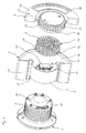
- eine Explosionszeichnung eines Statorgehäuses eines Pumpen-aggregats mit einem daran angeordneten Klemmenkasten und
- Fig. 2
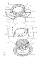
- eine Explosionszeichnung des in Fig. 1 dargestellten Statorgehäuses eines Pumpenaggregats mit dem daran angeordneten Klemmenkasten aus einem anderen Betrachtungswinkel.
- Fig. 1
- an exploded view of a stator housing of a pump unit with a terminal box disposed thereon and
- Fig. 2
- an exploded view of the stator housing of a pump unit shown in Fig. 1 with the terminal box disposed thereon from a different viewing angle.
Die Fig. 1 und 2 zeigen ein Statorgehäuse 2 eines Antriebsmotors eines Pumpenaggregats sowie einen an diesem Statorgehäuse 2 angeordneten Klemmenkasten bestehend aus einem ersten Klemmenkastenteil 4 und einem zweiten Klemmenkastenteil 6. Das Statorgehäuse 2 wird mit einer Fläche 3 an eine in den Zeichnungen nicht dargestellte Pumpe angeflanscht1 and 2 show a
Das erste Klemmenkastenteil 4 ist ein einstückiges Kunststoff-Spritzgussteil und besteht aus einem hohlen kreiszylindrischen Bereich 8 und einem an dessen Außenwand umfänglich angebundenen Bereich 10, der die Form eines hohlen Zylinderringsegments aufweist und dessen pumpenseitiger Stirnflächenbereich 12 durch eine Außenwandung verschlossen ist. Dabei sind die beiden Bereiche 8 und 10 des ersten Klemmenkastenteils 4 so aneinander angebunden, dass sie gemeinsam eine von der Pumpe abgewandte offene Stirnfläche des ersten Klemmenkastenteils 4 ausbilden. Diese weist die Form zweier annähernd halbkreisförmiger Kreisabschnitte mit unterschiedlichen Durchmessern auf, die an ihren Schnittkanten aneinander angebunden sind, wobei die Kreisabschnitte zueinander konzentrisch sind. Die Länge des zylinderringförmigen Bereichs 10 in Richtung der Statorlängsachse ist größer als die Länge des kreiszylindrischen Bereichs 8 des Klemmenkastens 4, so dass der Bereich 10 gegenüber dem Bereich 8 in Richtung Pumpe einen Vorsprung 11 ausbildet.The first
Das erste Klemmenkastenteil 4 ist so an dem Statorgehäuse 2 befestigt, dass die dem Statorgehäuse 2 zugewandte Außenwand des Vorsprungs 11 des Bereichs 10 an der Umfangsfläche des Statorgehäuses 2 anliegt und die Außenwandung des Bereichs 8 einen Teilbereich der Umfangsfläche und eine Stirnfläche 14 des Statorgehäuses 2 überdeckt, d.h. das Statorgehäuse 2 greift in den kreiszylindrischen bzw. topfförmigen Bereich 8 des Klemmenkastens 4 ein. Dazu korrespondiert der Innendurchmesser des Bereichs 8 mit dem Außendurchmesser des Statorgehäuses 2.The first
Von der von der Stirnfläche 14 des Statorgehäuse 2 abgewandten offenen Stirnfläche des ersten Klemmenkastenteils 4 her ist eine Platine 16 in einer zur Stirnfläche 14 beabstandeten parallelen Ebene in das Klemmenkastenteil 4 eingepasst, wobei die Platine 16 eine zur Stirnfläche bzw. zum Innenquerschnitt des Klemmenkastenteils 4 komplementäre Außenkontur aufweist. Auf der Platine 16 ist zumindest ein Teil einer Leistungs- und Steuerungselektronik des Pumpenaggregats angebracht, insbesondere an der dem Statorgehäuse 2 zugewandten Seite der Platine 16.From the
An der Stirnfläche 14 des Statorgehäuses 2 sind elektrische Steckkontakte 18 angeordnet. Diese Steckkontakte 18 sind in der Nähe der Umfangsfläche des Statorgehäuses 2 um den Umfang der Stirnfläche 14 verteilt. Die Platine 16 weist an Ihrer dem Statorgehäuse 2 zugewandten Seite Anschlussbuchsen 20 auf, deren Ausrichtung den Positionen der Steckkontakte 18 an der Stirnfläche 14 des Statorgehäuses 2 entspricht, so dass die Steckkontakte 18 des Statorgehäuses 2 im zusammengebauten Zustand in die Anschlussbuchsen 20 der Platine 16 eingreifen. Die in die Anschlussbuchsen 20 der Platine 16 eingreifenden Steckkontakte 18 stellen eine elektrische Verbindung zwischen dem Antriebsmotor des Pumpenaggregats und einer Stromversorgung sowie der Leistungs- und Steuerungselektronik her, die auf der Platine 16 angeordnet sind.At the
An ihrer dem Statorgehäuse 2 abgewandten Seite ist an der Platine 16 innerhalb des kreiszylindrischen Bereichs 8 des ersten Klemmenkastenteils 4 eine ebene Kontaktfläche 22 eines Eigenwärme erzeugenden Bauteils 24 angeordnet. Auf dieser Kontaktfläche 22 liegt im zusammengebauten Zustand des Klemmenkastens ein Wärmeverteiler 26 mit einer ebenen Grundplatte 28 auf.On its side facing away from the
Die Grundplatte 28 des Wärmeverteilers 26 ist kreisförmig ausgebildet und besitzt einen Durchmesser, der dem Innendurchmesser des kreiszylindrischen Bereichs 8 des ersten Klemmenkastenteils 4 angepasst ist. An der von der Platine 16 abgewandten Seite der Grundfläche 28 des Wärmeverteilers 26 sind eine Vielzahl von Kühlstiften 30 angeordnet, welche sich gleichmäßig über die Grundplatte 28 verteilt jeweils in eine Richtung normal zu dieser, d.h. parallel zur Statorlängsachse, erstrecken.The
Umhüllt wird der Wärmeverteiler 26 durch das zweite Klemmenkastenteil 6. Das zweite Klemmenkastenteil 6 bildet die Abdeckung des ersten Klemmenkastenteils 4. Dementsprechend weist das zweite Klemmenkastenteil 6 umfangsseitig die gleiche Außenkontur wie das erste Klemmenkastenteil 4 auf. So besitzt das zweite Klemmenkastenteil 6 einen kreiszylindrischen Grundkörper 32, der mit dem kreiszylindrischen Bereich 8 des ersten Klemmenkastenteils 4 korrespondiert sowie ein außenseitig an dessen Grundkörper 32 angeordnetes Zylinderringsegment 34, dessen Außenkontur der Außenkontur des Bereichs 10 des ersten Klemmenkastenteils 4 angepasst ist.The
Das Zylinderringsegment 34 ist so an dem Grundkörper 32 angeordnet bzw. einstückig mit diesem ausgebildet, dass der Grundkörper 32 und das Zylinderringsegment 34 statorseitig eine gemeinsame offene Stirnfläche des zweiten Klemmenkastenteils 6 ausbilden. Die Umfangskante 33 dieser offenen Stirnfläche liegt im geschlossenen Zustand des Klemmenkastens an der Umfangskante 35 des ersten Klemmenkastenteils 4 im Bereich der Platine 16 an, wobei der Kontaktbereich zwischen erstem und zweiten Klemmenkastenteil durch ein nicht dargestelltes Dichtelement bzw. Dichtmittel abgedichtet wird.The
Die Längsausdehnung des Zylinderringsegments 34 des zweiten Klemmenkastenteils 6 ist geringer als die des zylindrischen Grundkörpers 32 des zweiten Klemmenkastenteils 6. Auf diese Weise ragt der Grundkörper 32 gegenüber dem Zylinderringsegment 34 in einer Richtung weg vom Statorgehäuse 2 prominent hervor, so dass der Grundkörper 32 umfänglich eine vollständige Umfangswandung aufweist.The longitudinal extent of the
Der Grundkörper 32 des zweiten Klemmenkastenteils 6 weist an seinem vom Statorgehäuse 2 abgewandten Ende eine geschlossene Stirnfläche 38 auf, wohingegen an seiner kreiszylindrischen Umfangsfläche, welche gegenüber dem Zylinderringsegment 34 in Richtung der Statorlängsachse vorsteht, über den gesamten Umfang verteilt Lüftungsschlitze 36 angeordnet sind. Diese Lüftungsschlitze 36 ermöglichen, dass die Kühlstifte 30 des Wärmeverteilers 26 aus allen radialen Richtungen von Umgebungsluft angeströmt bzw. umströmt werden können.The
Das Zylinderringsegment 34 des ersten Klemmenkastenteils 4 weist eine dem Statorgehäuse 2 abgewandte geschlossene Stirnfläche 39 auf, die durch eine Ausnehmung 40 durchbrochen ist. Im Bereich dieser Ausnehmung 40 werden in den Fig. 1 und 2 nicht dargestellte Bedien- und Anzeigeelemente des Klemmenkastens angeordnet und mit der auf der Platine 16 angebrachten Elektronik verbunden.The
Um die in dem Klemmenkasten befindliche Elektronik des Pumpenaggregats vor Feuchtigkeit, Staub und anderen Fremdkörpern zu schützen, ist der kreiszylindrische Grundkörper 32 des zweiten Klemmenkastenteils 6 gegenüber dem Wärmeverteiler 26 abgedichtet. Die Abdichtung erfolgt über ein in den Fig. 1 und 2 nicht dargestelltes Dichtelement, bevorzugt durch einen Dichtring, der zwischen einer Umfangskante 42 der Grundplatte 28 des Wärmeverteilers 26 und einer Umfangskante 44 im Bereich der dem Statorgehäuse 2 zugewandten Stirnfläche des zylindrischen Grundkörpers 32 des zweiten Klemmenkastenteils 6 angeordnet ist. Die kreis- bzw. ringförmige Dicht- bzw. Anlagefläche zwischen Wärmeverteiler 26 und zweitem Klemmenkastenteil 6 ermöglicht dabei eine zuverlässige Abdichtung dieser Verbindungslinie. Hierdurch entsteht in dem Grundkörper 32 ein gegenüber dem übrigen Klemmenkasten feuchtigkeitsdicht abgeschlossener Raum, so dass durch die Lüftungsschlitze 36 eindringende Feuchtigkeit nicht die im Inneren des Klemmenkastens, insbesondere an der dem Statorgehäuse 2 zugewandten Seite des Wärmeverteilers 26, angeordnete Elektronik benetzen und damit eventuell zerstören kann.In order to protect the electronics of the pump set located in the terminal box from moisture, dust and other foreign bodies, the circular
Die oben beschriebene Gestaltung des Klemmenkastens, dessen in großen Teilen zylindrisches Gehäuse eine axiale Verlängerung des Statorgehäuses 2 ausbildet, bietet einen einfachen elektrischen Anschluss des Stators, Raum für einen großen Wärmeverteiler 26, der die im Betrieb anfallende Wärmeentwicklung innerhalb des Klemmenkastens in ausreichendem Maße ableiten kann, und nicht zuletzt eine ansprechende Form des gesamten Pumpenaggregats.The above-described design of the terminal box, whose largely cylindrical housing forms an axial extension of the
- 22
- Statorgehäusestator
- 33
- Flächearea
- 44
- erstes Klemmenkastenteilfirst terminal box part
- 66
- zweites Klemmenkastenteilsecond terminal box part
- 88th
- BereichArea
- 1010
- BereichArea
- 1111
- Vorsprunghead Start
- 1212
- Stirnflächeface
- 1414
- Stirnflächeface
- 1616
- Platinecircuit board
- 1818
- Steckkontaktplug contact
- 2020
- Anschlussbuchsesocket
- 2222
- Kontaktflächecontact area
- 2424
- Bauteilcomponent
- 2626
- Wärmeverteilerheat spreader
- 2828
- Grundplattebaseplate
- 3030
- Kühlstiftcooling pin
- 3232
- Grundkörperbody
- 3333
- Umfangskanteperipheral edge
- 3434
- ZylinderringsegmentCylinder ring segment
- 3535
- Umfangskanteperipheral edge
- 3636
- Lüftungsschlitzevents
- 3838
- Stirnflächeface
- 3939
- Stirnflächeface
- 4040
- Ausnehmungrecess
- 4242
- Umfangskanteperipheral edge
- 4444
- Umfangskanteperipheral edge
Claims (11)
- A pump unit with a stator housing (2) and with a terminal box attached to the outer side of the stator housing (2), characterised in that at least a first region (8, 32) of the terminal box covers an end-side (14) of the stator housing (2), and a heat distributor (26) for cooling electronic components (24) is arranged in this region (8, 32) of the terminal box, and a second region (10) of the terminal box is arranged on a peripheral section of the stator housing (2).
- A pump unit according to claim 1, characterised in that the shape of the heat distributor (26) is adapted to the end-side (14) of the stator housing (2).
- A pump unit according to claim 1 or 2, characterised in that the heat distributor (26) is arranged completely in the inside of the terminal box.
- A pump unit according to one of the preceding claims, characterised in that ventilation openings (36) are formed in an outer wall of the terminal box in the vicinity of the heat distributor (26).
- A pump unit according to one of the preceding claims, characterised in that an outer wall (38) of the terminal box, which covers the heat distributor (26) at the side of heat distributor which is distant to the stator housing (2), is designed in a closed manner, and that ventilation openings (36) are formed in an outer wall of the terminal box which peripherally surrounds the heat distributor (26), preferably distributed over the whole periphery.
- A pump unit according to one of the preceding claims, characterised in that operating- and/or display elements are arranged on an end-face (39) of the second region (34) of the terminal box, said end-face being distant to the end-side (14) of the stator housing (2).
- A pump unit according to claim 6, characterised in that the end-face (39) on which the operating- and/or display elements are arranged, is set back in the direction of the stator hsouing (2), with respect to the outer wall (38) of the terminal box, which covers the heat distributor at its side distant to the stator housing (2).
- A pump unit according to one of the preceding claims, characterised in that the heat distributor (26) comprises a multitude of cooling ribs and/or cooling pins (30) which extend at the side of the heat distributor (26) which is distant to the end-side (14) of the stator housing (2), preferably normally to the end-side (14) of the stator housing (2).
- A pump unit according to claim 8, characterised in that the cooling ribs and/or cooling pins (30) are arranged in a manner such that flow paths for cooling air are formed between them in every diameter direction of the heat distributor.
- A pump unit according to one of the preceding claims, characterised in that a sealing element is arranged between the peripheral region of the heat distributor (26) and an adjacent wall of the terminal box.
- A pump unit according to one of the preceding claims, characterised in that the heat distributor (26) consists of plastic.
Priority Applications (4)
| Application Number | Priority Date | Filing Date | Title |
|---|---|---|---|
| DE502004004636T DE502004004636D1 (en) | 2004-04-02 | 2004-04-02 | pump unit |
| EP04008040A EP1582751B1 (en) | 2004-04-02 | 2004-04-02 | Pump unit |
| AT04008040T ATE370334T1 (en) | 2004-04-02 | 2004-04-02 | PUMP UNIT |
| PL04008040T PL1582751T3 (en) | 2004-04-02 | 2004-04-02 | Pump unit |
Applications Claiming Priority (1)
| Application Number | Priority Date | Filing Date | Title |
|---|---|---|---|
| EP04008040A EP1582751B1 (en) | 2004-04-02 | 2004-04-02 | Pump unit |
Publications (2)
| Publication Number | Publication Date |
|---|---|
| EP1582751A1 EP1582751A1 (en) | 2005-10-05 |
| EP1582751B1 true EP1582751B1 (en) | 2007-08-15 |
Family
ID=34878247
Family Applications (1)
| Application Number | Title | Priority Date | Filing Date |
|---|---|---|---|
| EP04008040A Expired - Lifetime EP1582751B1 (en) | 2004-04-02 | 2004-04-02 | Pump unit |
Country Status (4)
| Country | Link |
|---|---|
| EP (1) | EP1582751B1 (en) |
| AT (1) | ATE370334T1 (en) |
| DE (1) | DE502004004636D1 (en) |
| PL (1) | PL1582751T3 (en) |
Cited By (1)
| Publication number | Priority date | Publication date | Assignee | Title |
|---|---|---|---|---|
| EP3418580A1 (en) | 2017-06-22 | 2018-12-26 | TACO ITALIA S.r.l. | Fluid circulator with heat sink or dissipator |
Families Citing this family (4)
| Publication number | Priority date | Publication date | Assignee | Title |
|---|---|---|---|---|
| EP2166230B1 (en) * | 2008-09-19 | 2018-11-21 | Grundfos Management A/S | Pump power unit |
| EP2608364B1 (en) | 2011-12-23 | 2018-05-09 | Grundfos Holding A/S | Electrical drive motor |
| EP2905472B1 (en) * | 2011-12-23 | 2020-03-04 | Grundfos Holding A/S | Wet running circulation pump |
| EP2607707B2 (en) | 2011-12-23 | 2022-11-23 | Grundfos Holding A/S | Electric motor |
Family Cites Families (5)
| Publication number | Priority date | Publication date | Assignee | Title |
|---|---|---|---|---|
| DE19511114C1 (en) * | 1995-03-25 | 1996-08-29 | Grundfos As | Electric motor |
| US6081056A (en) * | 1996-03-07 | 2000-06-27 | Seiko Epson Corporation | Motor and method for producing the same |
| DE29700643U1 (en) * | 1997-01-15 | 1997-03-13 | Siemens AG, 80333 München | Cooling concept for an electric drive system |
| DE10114923C2 (en) * | 2001-03-26 | 2003-05-08 | Grundfos As | Terminal box for an electric motor |
| DE10239512A1 (en) * | 2002-08-28 | 2004-03-11 | Minebea Co. Ltd., A Japanese Corporation | Power/control application structure for direct current electric motor e.g. in motor vehicles, has first and second printed circuit boards with control/power electronic parts and an electrically insulated substrate to dissipate heat |
-
2004
- 2004-04-02 PL PL04008040T patent/PL1582751T3/en unknown
- 2004-04-02 DE DE502004004636T patent/DE502004004636D1/en not_active Expired - Lifetime
- 2004-04-02 AT AT04008040T patent/ATE370334T1/en not_active IP Right Cessation
- 2004-04-02 EP EP04008040A patent/EP1582751B1/en not_active Expired - Lifetime
Cited By (3)
| Publication number | Priority date | Publication date | Assignee | Title |
|---|---|---|---|---|
| EP3418580A1 (en) | 2017-06-22 | 2018-12-26 | TACO ITALIA S.r.l. | Fluid circulator with heat sink or dissipator |
| EP3418580B1 (en) | 2017-06-22 | 2020-01-29 | TACO ITALIA S.r.l. | Fluid circulator with heat sink or dissipator |
| US11542957B2 (en) | 2017-06-22 | 2023-01-03 | Taco Italia S.R.L. | Fluid circulator with heat sink or dissipator |
Also Published As
| Publication number | Publication date |
|---|---|
| DE502004004636D1 (en) | 2007-09-27 |
| ATE370334T1 (en) | 2007-09-15 |
| EP1582751A1 (en) | 2005-10-05 |
| PL1582751T3 (en) | 2008-01-31 |
Similar Documents
| Publication | Publication Date | Title |
|---|---|---|
| EP3232543B1 (en) | Pump motor having an air-gap shroud | |
| EP0958646B1 (en) | Electric motor with an upstream frequency converter | |
| EP1714375B1 (en) | Brush system for an electric drive unit | |
| DE19828518A1 (en) | Rectifier modular unit on a three-phase alternator | |
| EP2166230A1 (en) | Pump power unit | |
| EP2750265B1 (en) | Pump power unit | |
| DE10313274A1 (en) | Electric motor with high IP protection | |
| DE102005032968A1 (en) | Frequency converter motor for drive application, has frequency converter that is radially arranged on motor, where side of housing of frequency converter facing motor is U-shapely designed and has different high cooling fins | |
| DE10313273A1 (en) | Electronically-commutated external rotor electric motor has motor housing of high IP protection type and annular flange with external cooling ribs integral with bearing sleeve for external rotor | |
| DE112015002495T5 (en) | Electric power converting device | |
| DE102015119560A1 (en) | ELECTRONIC DEVICE AND MOTOR DRIVEN COMPRESSOR PROVIDED IN A VEHICLE | |
| DE102010040399A1 (en) | Housing for receiving an electric drive | |
| WO2014102068A2 (en) | Pump unit | |
| EP1582751B1 (en) | Pump unit | |
| EP2750267B1 (en) | Pump power unit | |
| WO2004013944A1 (en) | Electric motor with a high ip-protective system | |
| EP3182565B1 (en) | Electronics housing with cooling fins | |
| EP3356679A1 (en) | Compact cooling device having a radial fan adhesively bonded to the cooling body | |
| DE102005032970B3 (en) | Converter motor has motor, converter and separately driven fan whereby housing of motor is provided with radially running cooling fins and the converter is radially arranged on motor | |
| EP1460748B1 (en) | Pump unit | |
| DE10133767A1 (en) | Commutator motor with a cylindrical motor housing | |
| DE19956429A1 (en) | Electric motor for a centrifugal pump in particular | |
| EP1796246A1 (en) | Electrical machine and method for cooling the electronic part of an electrical machine | |
| DE19904279A1 (en) | Semiconductor component, especially for an electric motor frequency converter, has an electrically non-conductive housing directly surrounding cooling bodies of a non-insulated power semiconductor housing | |
| DE102015000637A1 (en) | Fan with fan housing |
Legal Events
| Date | Code | Title | Description |
|---|---|---|---|
| PUAI | Public reference made under article 153(3) epc to a published international application that has entered the european phase |
Free format text: ORIGINAL CODE: 0009012 |
|
| AK | Designated contracting states |
Kind code of ref document: A1 Designated state(s): AT BE BG CH CY CZ DE DK EE ES FI FR GB GR HU IE IT LI LU MC NL PL PT RO SE SI SK TR |
|
| AX | Request for extension of the european patent |
Extension state: AL HR LT LV MK |
|
| 17P | Request for examination filed |
Effective date: 20050811 |
|
| AKX | Designation fees paid |
Designated state(s): AT BE BG CH CY CZ DE DK EE ES FI FR GB GR HU IE IT LI LU MC NL PL PT RO SE SI SK TR |
|
| GRAP | Despatch of communication of intention to grant a patent |
Free format text: ORIGINAL CODE: EPIDOSNIGR1 |
|
| GRAS | Grant fee paid |
Free format text: ORIGINAL CODE: EPIDOSNIGR3 |
|
| GRAA | (expected) grant |
Free format text: ORIGINAL CODE: 0009210 |
|
| AK | Designated contracting states |
Kind code of ref document: B1 Designated state(s): AT BE BG CH CY CZ DE DK EE ES FI FR GB GR HU IE IT LI LU MC NL PL PT RO SE SI SK TR |
|
| REG | Reference to a national code |
Ref country code: GB Ref legal event code: FG4D Free format text: NOT ENGLISH |
|
| REG | Reference to a national code |
Ref country code: CH Ref legal event code: EP |
|
| REG | Reference to a national code |
Ref country code: IE Ref legal event code: FG4D Free format text: LANGUAGE OF EP DOCUMENT: GERMAN |
|
| REF | Corresponds to: |
Ref document number: 502004004636 Country of ref document: DE Date of ref document: 20070927 Kind code of ref document: P |
|
| GBT | Gb: translation of ep patent filed (gb section 77(6)(a)/1977) |
Effective date: 20071022 |
|
| PG25 | Lapsed in a contracting state [announced via postgrant information from national office to epo] |
Ref country code: FI Free format text: LAPSE BECAUSE OF FAILURE TO SUBMIT A TRANSLATION OF THE DESCRIPTION OR TO PAY THE FEE WITHIN THE PRESCRIBED TIME-LIMIT Effective date: 20070815 Ref country code: NL Free format text: LAPSE BECAUSE OF FAILURE TO SUBMIT A TRANSLATION OF THE DESCRIPTION OR TO PAY THE FEE WITHIN THE PRESCRIBED TIME-LIMIT Effective date: 20070815 Ref country code: ES Free format text: LAPSE BECAUSE OF FAILURE TO SUBMIT A TRANSLATION OF THE DESCRIPTION OR TO PAY THE FEE WITHIN THE PRESCRIBED TIME-LIMIT Effective date: 20071126 Ref country code: BG Free format text: LAPSE BECAUSE OF FAILURE TO SUBMIT A TRANSLATION OF THE DESCRIPTION OR TO PAY THE FEE WITHIN THE PRESCRIBED TIME-LIMIT Effective date: 20071115 |
|
| REG | Reference to a national code |
Ref country code: PL Ref legal event code: T3 |
|
| NLV1 | Nl: lapsed or annulled due to failure to fulfill the requirements of art. 29p and 29m of the patents act | ||
| ET | Fr: translation filed | ||
| REG | Reference to a national code |
Ref country code: IE Ref legal event code: FD4D |
|
| PG25 | Lapsed in a contracting state [announced via postgrant information from national office to epo] |
Ref country code: GR Free format text: LAPSE BECAUSE OF FAILURE TO SUBMIT A TRANSLATION OF THE DESCRIPTION OR TO PAY THE FEE WITHIN THE PRESCRIBED TIME-LIMIT Effective date: 20071116 Ref country code: DK Free format text: LAPSE BECAUSE OF FAILURE TO SUBMIT A TRANSLATION OF THE DESCRIPTION OR TO PAY THE FEE WITHIN THE PRESCRIBED TIME-LIMIT Effective date: 20070815 |
|
| PG25 | Lapsed in a contracting state [announced via postgrant information from national office to epo] |
Ref country code: SK Free format text: LAPSE BECAUSE OF FAILURE TO SUBMIT A TRANSLATION OF THE DESCRIPTION OR TO PAY THE FEE WITHIN THE PRESCRIBED TIME-LIMIT Effective date: 20070815 Ref country code: CZ Free format text: LAPSE BECAUSE OF FAILURE TO SUBMIT A TRANSLATION OF THE DESCRIPTION OR TO PAY THE FEE WITHIN THE PRESCRIBED TIME-LIMIT Effective date: 20070815 Ref country code: IE Free format text: LAPSE BECAUSE OF FAILURE TO SUBMIT A TRANSLATION OF THE DESCRIPTION OR TO PAY THE FEE WITHIN THE PRESCRIBED TIME-LIMIT Effective date: 20070815 Ref country code: PT Free format text: LAPSE BECAUSE OF FAILURE TO SUBMIT A TRANSLATION OF THE DESCRIPTION OR TO PAY THE FEE WITHIN THE PRESCRIBED TIME-LIMIT Effective date: 20080115 |
|
| PLBE | No opposition filed within time limit |
Free format text: ORIGINAL CODE: 0009261 |
|
| STAA | Information on the status of an ep patent application or granted ep patent |
Free format text: STATUS: NO OPPOSITION FILED WITHIN TIME LIMIT |
|
| PG25 | Lapsed in a contracting state [announced via postgrant information from national office to epo] |
Ref country code: SE Free format text: LAPSE BECAUSE OF FAILURE TO SUBMIT A TRANSLATION OF THE DESCRIPTION OR TO PAY THE FEE WITHIN THE PRESCRIBED TIME-LIMIT Effective date: 20071115 Ref country code: RO Free format text: LAPSE BECAUSE OF FAILURE TO SUBMIT A TRANSLATION OF THE DESCRIPTION OR TO PAY THE FEE WITHIN THE PRESCRIBED TIME-LIMIT Effective date: 20070815 |
|
| 26N | No opposition filed |
Effective date: 20080516 |
|
| BERE | Be: lapsed |
Owner name: RUNDFOS A/S Effective date: 20080430 |
|
| PG25 | Lapsed in a contracting state [announced via postgrant information from national office to epo] |
Ref country code: MC Free format text: LAPSE BECAUSE OF NON-PAYMENT OF DUE FEES Effective date: 20080430 |
|
| REG | Reference to a national code |
Ref country code: CH Ref legal event code: PL |
|
| PG25 | Lapsed in a contracting state [announced via postgrant information from national office to epo] |
Ref country code: LI Free format text: LAPSE BECAUSE OF NON-PAYMENT OF DUE FEES Effective date: 20080430 Ref country code: CH Free format text: LAPSE BECAUSE OF NON-PAYMENT OF DUE FEES Effective date: 20080430 Ref country code: EE Free format text: LAPSE BECAUSE OF FAILURE TO SUBMIT A TRANSLATION OF THE DESCRIPTION OR TO PAY THE FEE WITHIN THE PRESCRIBED TIME-LIMIT Effective date: 20070815 |
|
| PG25 | Lapsed in a contracting state [announced via postgrant information from national office to epo] |
Ref country code: BE Free format text: LAPSE BECAUSE OF NON-PAYMENT OF DUE FEES Effective date: 20080430 |
|
| PG25 | Lapsed in a contracting state [announced via postgrant information from national office to epo] |
Ref country code: SI Free format text: LAPSE BECAUSE OF FAILURE TO SUBMIT A TRANSLATION OF THE DESCRIPTION OR TO PAY THE FEE WITHIN THE PRESCRIBED TIME-LIMIT Effective date: 20070815 |
|
| PG25 | Lapsed in a contracting state [announced via postgrant information from national office to epo] |
Ref country code: CY Free format text: LAPSE BECAUSE OF FAILURE TO SUBMIT A TRANSLATION OF THE DESCRIPTION OR TO PAY THE FEE WITHIN THE PRESCRIBED TIME-LIMIT Effective date: 20070815 |
|
| PG25 | Lapsed in a contracting state [announced via postgrant information from national office to epo] |
Ref country code: AT Free format text: LAPSE BECAUSE OF NON-PAYMENT OF DUE FEES Effective date: 20080402 |
|
| PG25 | Lapsed in a contracting state [announced via postgrant information from national office to epo] |
Ref country code: LU Free format text: LAPSE BECAUSE OF NON-PAYMENT OF DUE FEES Effective date: 20080402 Ref country code: HU Free format text: LAPSE BECAUSE OF FAILURE TO SUBMIT A TRANSLATION OF THE DESCRIPTION OR TO PAY THE FEE WITHIN THE PRESCRIBED TIME-LIMIT Effective date: 20080216 |
|
| PG25 | Lapsed in a contracting state [announced via postgrant information from national office to epo] |
Ref country code: TR Free format text: LAPSE BECAUSE OF FAILURE TO SUBMIT A TRANSLATION OF THE DESCRIPTION OR TO PAY THE FEE WITHIN THE PRESCRIBED TIME-LIMIT Effective date: 20070815 |
|
| REG | Reference to a national code |
Ref country code: FR Ref legal event code: PLFP Year of fee payment: 13 |
|
| REG | Reference to a national code |
Ref country code: FR Ref legal event code: PLFP Year of fee payment: 14 |
|
| REG | Reference to a national code |
Ref country code: FR Ref legal event code: PLFP Year of fee payment: 15 |
|
| PGFP | Annual fee paid to national office [announced via postgrant information from national office to epo] |
Ref country code: PL Payment date: 20220323 Year of fee payment: 19 |
|
| PGFP | Annual fee paid to national office [announced via postgrant information from national office to epo] |
Ref country code: IT Payment date: 20220429 Year of fee payment: 19 Ref country code: GB Payment date: 20220425 Year of fee payment: 19 Ref country code: FR Payment date: 20220420 Year of fee payment: 19 Ref country code: DE Payment date: 20220425 Year of fee payment: 19 |
|
| REG | Reference to a national code |
Ref country code: DE Ref legal event code: R082 Ref document number: 502004004636 Country of ref document: DE |
|
| REG | Reference to a national code |
Ref country code: DE Ref legal event code: R119 Ref document number: 502004004636 Country of ref document: DE |
|
| GBPC | Gb: european patent ceased through non-payment of renewal fee |
Effective date: 20230402 |
|
| PG25 | Lapsed in a contracting state [announced via postgrant information from national office to epo] |
Ref country code: GB Free format text: LAPSE BECAUSE OF NON-PAYMENT OF DUE FEES Effective date: 20230402 |
|
| PG25 | Lapsed in a contracting state [announced via postgrant information from national office to epo] |
Ref country code: GB Free format text: LAPSE BECAUSE OF NON-PAYMENT OF DUE FEES Effective date: 20230402 Ref country code: FR Free format text: LAPSE BECAUSE OF NON-PAYMENT OF DUE FEES Effective date: 20230430 Ref country code: DE Free format text: LAPSE BECAUSE OF NON-PAYMENT OF DUE FEES Effective date: 20231103 |
|
| PG25 | Lapsed in a contracting state [announced via postgrant information from national office to epo] |
Ref country code: IT Free format text: LAPSE BECAUSE OF NON-PAYMENT OF DUE FEES Effective date: 20230402 |
|
| PG25 | Lapsed in a contracting state [announced via postgrant information from national office to epo] |
Ref country code: PL Free format text: LAPSE BECAUSE OF NON-PAYMENT OF DUE FEES Effective date: 20230402 |
|
| PG25 | Lapsed in a contracting state [announced via postgrant information from national office to epo] |
Ref country code: PL Free format text: LAPSE BECAUSE OF NON-PAYMENT OF DUE FEES Effective date: 20230402 |