EP1582697A1 - Cavity on-board injection for leakage flows - Google Patents
Cavity on-board injection for leakage flows Download PDFInfo
- Publication number
- EP1582697A1 EP1582697A1 EP05251997A EP05251997A EP1582697A1 EP 1582697 A1 EP1582697 A1 EP 1582697A1 EP 05251997 A EP05251997 A EP 05251997A EP 05251997 A EP05251997 A EP 05251997A EP 1582697 A1 EP1582697 A1 EP 1582697A1
- Authority
- EP
- European Patent Office
- Prior art keywords
- section
- combustion
- cooling
- turbine section
- turbine engine
- Prior art date
- Legal status (The legal status is an assumption and is not a legal conclusion. Google has not performed a legal analysis and makes no representation as to the accuracy of the status listed.)
- Granted
Links
- 238000002347 injection Methods 0.000 title 1
- 239000007924 injection Substances 0.000 title 1
- 238000001816 cooling Methods 0.000 claims abstract description 45
- 230000003071 parasitic effect Effects 0.000 claims abstract description 42
- 239000011888 foil Substances 0.000 claims abstract description 12
- 239000003570 air Substances 0.000 claims description 57
- 239000007789 gas Substances 0.000 claims description 56
- 238000002485 combustion reaction Methods 0.000 claims description 29
- 239000012530 fluid Substances 0.000 claims description 25
- 239000000567 combustion gas Substances 0.000 claims description 22
- 239000003607 modifier Substances 0.000 claims description 18
- 239000000446 fuel Substances 0.000 claims description 8
- 238000000034 method Methods 0.000 claims description 8
- 239000012080 ambient air Substances 0.000 claims description 3
- 230000000593 degrading effect Effects 0.000 abstract description 5
- 238000010276 construction Methods 0.000 description 4
- 238000010586 diagram Methods 0.000 description 4
- 238000005094 computer simulation Methods 0.000 description 2
- 230000001627 detrimental effect Effects 0.000 description 2
- 238000012986 modification Methods 0.000 description 2
- 230000004048 modification Effects 0.000 description 2
- 230000015556 catabolic process Effects 0.000 description 1
- 238000007796 conventional method Methods 0.000 description 1
- 238000006731 degradation reaction Methods 0.000 description 1
- 238000005553 drilling Methods 0.000 description 1
- 238000010438 heat treatment Methods 0.000 description 1
- 230000004941 influx Effects 0.000 description 1
- 238000003801 milling Methods 0.000 description 1
- 238000005192 partition Methods 0.000 description 1
- 238000010248 power generation Methods 0.000 description 1
- 230000003068 static effect Effects 0.000 description 1
- 238000009423 ventilation Methods 0.000 description 1
Images



Classifications
-
- F—MECHANICAL ENGINEERING; LIGHTING; HEATING; WEAPONS; BLASTING
- F01—MACHINES OR ENGINES IN GENERAL; ENGINE PLANTS IN GENERAL; STEAM ENGINES
- F01D—NON-POSITIVE DISPLACEMENT MACHINES OR ENGINES, e.g. STEAM TURBINES
- F01D25/00—Component parts, details, or accessories, not provided for in, or of interest apart from, other groups
- F01D25/08—Cooling; Heating; Heat-insulation
- F01D25/12—Cooling
-
- F—MECHANICAL ENGINEERING; LIGHTING; HEATING; WEAPONS; BLASTING
- F01—MACHINES OR ENGINES IN GENERAL; ENGINE PLANTS IN GENERAL; STEAM ENGINES
- F01D—NON-POSITIVE DISPLACEMENT MACHINES OR ENGINES, e.g. STEAM TURBINES
- F01D5/00—Blades; Blade-carrying members; Heating, heat-insulating, cooling or antivibration means on the blades or the members
- F01D5/02—Blade-carrying members, e.g. rotors
- F01D5/08—Heating, heat-insulating or cooling means
- F01D5/081—Cooling fluid being directed on the side of the rotor disc or at the roots of the blades
-
- F—MECHANICAL ENGINEERING; LIGHTING; HEATING; WEAPONS; BLASTING
- F02—COMBUSTION ENGINES; HOT-GAS OR COMBUSTION-PRODUCT ENGINE PLANTS
- F02C—GAS-TURBINE PLANTS; AIR INTAKES FOR JET-PROPULSION PLANTS; CONTROLLING FUEL SUPPLY IN AIR-BREATHING JET-PROPULSION PLANTS
- F02C7/00—Features, components parts, details or accessories, not provided for in, or of interest apart form groups F02C1/00 - F02C6/00; Air intakes for jet-propulsion plants
- F02C7/12—Cooling of plants
- F02C7/16—Cooling of plants characterised by cooling medium
- F02C7/18—Cooling of plants characterised by cooling medium the medium being gaseous, e.g. air
-
- F—MECHANICAL ENGINEERING; LIGHTING; HEATING; WEAPONS; BLASTING
- F05—INDEXING SCHEMES RELATING TO ENGINES OR PUMPS IN VARIOUS SUBCLASSES OF CLASSES F01-F04
- F05D—INDEXING SCHEME FOR ASPECTS RELATING TO NON-POSITIVE-DISPLACEMENT MACHINES OR ENGINES, GAS-TURBINES OR JET-PROPULSION PLANTS
- F05D2240/00—Components
- F05D2240/80—Platforms for stationary or moving blades
- F05D2240/81—Cooled platforms
-
- F—MECHANICAL ENGINEERING; LIGHTING; HEATING; WEAPONS; BLASTING
- F05—INDEXING SCHEMES RELATING TO ENGINES OR PUMPS IN VARIOUS SUBCLASSES OF CLASSES F01-F04
- F05D—INDEXING SCHEME FOR ASPECTS RELATING TO NON-POSITIVE-DISPLACEMENT MACHINES OR ENGINES, GAS-TURBINES OR JET-PROPULSION PLANTS
- F05D2260/00—Function
- F05D2260/60—Fluid transfer
-
- F—MECHANICAL ENGINEERING; LIGHTING; HEATING; WEAPONS; BLASTING
- F05—INDEXING SCHEMES RELATING TO ENGINES OR PUMPS IN VARIOUS SUBCLASSES OF CLASSES F01-F04
- F05D—INDEXING SCHEME FOR ASPECTS RELATING TO NON-POSITIVE-DISPLACEMENT MACHINES OR ENGINES, GAS-TURBINES OR JET-PROPULSION PLANTS
- F05D2260/00—Function
- F05D2260/60—Fluid transfer
- F05D2260/602—Drainage
- F05D2260/6022—Drainage of leakage having past a seal
-
- Y—GENERAL TAGGING OF NEW TECHNOLOGICAL DEVELOPMENTS; GENERAL TAGGING OF CROSS-SECTIONAL TECHNOLOGIES SPANNING OVER SEVERAL SECTIONS OF THE IPC; TECHNICAL SUBJECTS COVERED BY FORMER USPC CROSS-REFERENCE ART COLLECTIONS [XRACs] AND DIGESTS
- Y02—TECHNOLOGIES OR APPLICATIONS FOR MITIGATION OR ADAPTATION AGAINST CLIMATE CHANGE
- Y02T—CLIMATE CHANGE MITIGATION TECHNOLOGIES RELATED TO TRANSPORTATION
- Y02T50/00—Aeronautics or air transport
- Y02T50/60—Efficient propulsion technologies, e.g. for aircraft
Definitions
- the present disclosure generally relates to gas turbine engines and, more particularly, relates to the turbine section of gas turbine engines.
- Gas turbine engines are widely applied machines for generating power or thrust. Most typically, they are employed on modem aircraft to provide the propulsion necessary for flight. They may also be used on board such aircraft for power generations or in an APU (Auxiliary Power Unit) capacity to provide for onboard heating, cooling, and ventilation, as well as the operational power and lighting systems onboard the aircraft within the cockpit, passenger cabin, and the like. They may also be used in land-based applications for generation of electrical power or mechanical horsepower in myriad vehicles and pieces of machinery.
- APU Advanced Power Unit
- a compressor section In a typical gas turbine engine, three main sections are provided, namely, a compressor section, a combustion section, and a turbine section.
- a compressor section Within the compressor section, ambient air is ingested, highly compressed, and directed through a downstream diffuser into the combustion section.
- the highly compressed air Within the combustion section, the highly compressed air is mixed with fuel within an annular combustion chamber and burned at extremely high temperatures generating massive levels of heat energy.
- ignition within a gas turbine engine is continuous, thereby increasing the high power levels attainable by the engine.
- the extremely hot combustion gases are directed to the turbine section downstream of the combustion chamber.
- both the turbine section and the compressor section are mounted on the same shaft assembly, rotation of the turbine blades, upon contact with the rapidly expanding and hot combustion gases, causes the shaft to which they are mounted to rotate and in turn causes the compressor blades, also mounted to the shaft, to rotate and thus complete the engine cycle.
- the discharge of the rapidly expanding hot gases at high velocities from the turbine causes the engine to generate the aforementioned thrust needed for aircraft operation.
- a gas turbine engine which may comprise a compressor section, a combustion section, a turbine section, and an axial flow plenum extending through the engine.
- the combustion section may be downstream of the compressor section, while the turbine section may be downstream of the combustion section.
- the axial flow plenum may include at least one outlet fluidically coupled to the turbine section.
- the gas turbine engine may further include a fluid flow directional modifier disposed proximate the axial flow plenum outlet.
- a gas turbine engine which may include a compressor section, a combustion section, a turbine section, and a turbine section cooling system.
- the combustion section may be downstream of the compressor section with the turbine section being downstream of the combustion section.
- Combustion gases may traverse from the combustion section through the turbine section along a combustion gas flow path.
- the turbine section cooling system may be proximate to the turbine section and direct cooling air and parasitic leakage into the turbine section in the direction of the combustion gas flow path.
- a method of operating a gas turbine engine which may include the steps of compressing air in a compressor section of the gas turbine engine, directing compressed air into a combustion section of the gas turbine engine, injecting fuel into the combustion section of the gas turbine engine, directing combustion gases from the combustion section into a turbine section of the gas turbine engine along a combustion gas flow path, and introducing cooling air and parasitic leakage into the turbine section substantially in the direction of the combustion gas flow path.
- a gas turbine engine constructed in accordance with the teachings of the disclosure is generally referred to by reference numeral 20.
- the gas turbine engine 20 includes a compressor section 22, a combustion section 24, and a turbine section 26.
- ambient air is compressed within compressor section 22, and directed to combustion section 24 where it is combined with fuel and ignited.
- the hot combustion gases resulting from ignition are then directed to the turbine section 26 and cause the turbine section to rotate and exhaust air at extremely high velocities.
- the turbine section 26 includes a plurality of stator vanes 28 intermeshed with a plurality of rotor blades 30.
- the stator vanes 28 are fixedly mounted to casing 32 and extend radially inwardly, whereas the rotor blades 30 are mounted to a rotatable rotor 34 and extend radially outwardly from a rotatable shaft 36.
- Combustion gases exiting the combustion section 24 are directed by the shape and angle of the turbine vanes 28 so as to impart force against the rotor blades 30 thus causing the rotor 34 and shaft 36 to rotate.
- the present disclosure teaches a turbine section cooling system and method for directing parasitic leakage air into the turbine section 26 in a direction substantially similar to gas flow path 38 as indicated by arrow 39 (See Fig. 3).
- a number of specific structures are disclosed and described below which enable the parasitic leakage air, also referred to as secondary fluid flow and cooling air, to be so introduced to the turbine section 26. In doing so, not only is the turbine section 26 adequately cooled, but it is cooled without substantially effecting the efficiency of the engine.
- parasitic leakage is introduced to the turbine section 26 along a radially central plenum 40 substantially coincident with shaft 36 before being directed radially outwardly along path 41 through apertures 42.
- the central plenum 40, path 41, and apertures 42 combine to form as secondary flow cavity 43.
- Fig. 3 indicates the direction of such parasitic leakage air flow through the cavity 43.
- the parasitic leakage air is able to be introduced substantially along the direction of gas flow path 38 due to the provision of a plurality of fluid flow directional modifiers 44 provided proximate a trailing edge 45 of the turbine vanes 28.
- the fluid flow directional modifiers 44 are provided in the form of turning foils 44, wherein each turning foil 44 is provided with an arcuate surface 46 (Fig. 5) which encourages the parasitic leakage air exiting through the secondary flow cavity 43 to be turned so as to be substantially parallel to the gas flow path 38.
- the parasitic leakage air not only is able to cool the turbine section 26 to a degree sufficient to protect the hardware of the turbine section 26, but is also able to do so without substantially degrading the performance characteristics of the engine 20.
- a single fluid flow directional modifier could be prescribed.
- the turning foils 44 can be cast directly into the turbine vanes 28 or may be separately fabricated and welded and/or brazed onto the vanes 28.
- Figs. 4 and 5 depict the foils 44 extending directly from a wall 47 forming the trailing edge 45 of the turbine vane 28.
- the foils 44 may work in concert with a discourager or lip 48 extending from a leading edge 49 of the turbine blade 30 to form the labyrinthine path 41 as shown best in Fig. 3. In so doing, the parasitic leakage air is encouraged to enter the turbine 26 in the desired direction.
- FIG. 6A and 6B depict a prior art secondary cooling and parasitic leakage system 50 wherein parasitic leakage air is directed radially outwardly and thus transverse to the direction of gas flow in a typical gas turbine engine.
- parasitic leakage air is directed radially outwardly and thus transverse to the direction of gas flow in a typical gas turbine engine.
- substantial recirculation represented by area 51 is generated within the turbine section 26 thereby substantially slowing overall gas flow within the turbine section 26 and thus substantially degrading engine performance.
- the secondary flow cavity 43 of the present disclosure introduces the cooling air substantially in the direction of the gas flow path 38 thereby providing the desired cooling characteristics without substantially effecting engine performance.
- the area of recirculation 52 is substantially smaller than that depicted in Fig. 6B.
- a turbine section cooling system constructed in accordance with the teachings of the disclosure is generally referred to by reference numeral 53.
- the second embodiment of the present disclosure is generally concerned with directing cooling air into the turbine section 26 of the engine 20 without substantially degrading engine performance.
- it is able to do so by using a plurality of fluid flow directional modifiers in the form of turning holes 54 as opposed to a plurality of turning foils 44 as with the first embodiment. More specifically, as depicted in Figs.
- a shroud 56 may be provided radially inwardly of a turbine vane wall 58 with the plurality of turning holes 54 being provided therebetween and separated by a plurality of internal partitions 60.
- parasitic leakage air is directed through the secondary flow cavity 43 along a first plenum 62 before being directed through a second plenum 64 and ultimately through the plurality of turning holes 54.
- the air exiting from the turning holes 54 along path 65 is substantially aligned with the overall gas flow path 66 of the engine 20.
- the plurality of turning holes 54 may be alternatively fabricated as by drilling, milling, or any other conventional method known to one of ordinary skill in the art of gas turbine engines. Moreover, grooves or the like, as opposed to fully encircled holes, may be machined into the structure for the same purpose.
- the cooling and parasitic leakage air may be directed radially inwardly as opposed to the previously identified embodiments wherein the parasitic leakage air is directed radially outwardly into the turbine section 26.
- air may be directed along an outer annular plenum 70 with a plurality of fluid flow directional modifiers 72 being provided at a radially outwardly disposed section of the turbine section 26.
- Such modifiers 72 may be provided in the form of turning foils, turning holes, grooves or other embodiments indicated or suggested above.
- the secondary fluid flow of the parasitic leakage air generated by this alternative embodiment is directed into the turbine section 26 along an arrow 74 which is substantially similar to the primary fluid flow of the combustion gases as indicated by arrow 76. Accordingly, the parasitic leakage air is provided within the turbine section 26 without substantial degradation in engine performance as with the previously identified embodiments.
- FIG. 11 and 12 Another embodiment of a cooling and parasitic leakage air system 100 constructed in accordance with the teachings of the disclosure is depicted in Figs. 11 and 12. As depicted therein, cooling and parasitic leakage air is directed along secondary air flow cavity 101 before being directed into the turbine section 102 in the direction of arrow 104. In accordance with the teachings of the disclosure, such secondary air flow is in substantial alignment with the primary fluid flow 106 of the gas flow path through the turbine section. In so doing, the turbine section 102 is able to be cooled without detrimentally affecting the efficiency of the engine.
- the system 100 may include a fluid flow direction modifier in the form of a turning hole 108 provided in a heat shield 110. The turning hole 108 is provided at an angle resulting in the desired secondary cooling flow 104.
- the parasitic leakage air is accelerated into the turbine section 102 to further facilitate cooling. It is able to do so through the provision of a seal 112 within the secondary flow cavity 101, specifically chamber 114, which creates a pressure drop across the turning hole 108.
Landscapes
- Engineering & Computer Science (AREA)
- Mechanical Engineering (AREA)
- General Engineering & Computer Science (AREA)
- Chemical & Material Sciences (AREA)
- Combustion & Propulsion (AREA)
- Turbine Rotor Nozzle Sealing (AREA)
Abstract
Description
- The present disclosure generally relates to gas turbine engines and, more particularly, relates to the turbine section of gas turbine engines.
- Gas turbine engines are widely applied machines for generating power or thrust. Most typically, they are employed on modem aircraft to provide the propulsion necessary for flight. They may also be used on board such aircraft for power generations or in an APU (Auxiliary Power Unit) capacity to provide for onboard heating, cooling, and ventilation, as well as the operational power and lighting systems onboard the aircraft within the cockpit, passenger cabin, and the like. They may also be used in land-based applications for generation of electrical power or mechanical horsepower in myriad vehicles and pieces of machinery.
- In a typical gas turbine engine, three main sections are provided, namely, a compressor section, a combustion section, and a turbine section. Within the compressor section, ambient air is ingested, highly compressed, and directed through a downstream diffuser into the combustion section. Within the combustion section, the highly compressed air is mixed with fuel within an annular combustion chamber and burned at extremely high temperatures generating massive levels of heat energy. Moreover, as opposed to internal combustion engines, wherein the ignition of the fuel is intermittent every two or four strokes of the engine, ignition within a gas turbine engine is continuous, thereby increasing the high power levels attainable by the engine.
- From the combustion section, the extremely hot combustion gases are directed to the turbine section downstream of the combustion chamber. As both the turbine section and the compressor section are mounted on the same shaft assembly, rotation of the turbine blades, upon contact with the rapidly expanding and hot combustion gases, causes the shaft to which they are mounted to rotate and in turn causes the compressor blades, also mounted to the shaft, to rotate and thus complete the engine cycle. The discharge of the rapidly expanding hot gases at high velocities from the turbine causes the engine to generate the aforementioned thrust needed for aircraft operation.
- While effective, difficulties encountered in the design and operation of gas turbine engines result from the extreme temperatures to which the engine components, particularly the turbine blades, are exposed. Prior art devices have therefore devised schemes for directing cooling air into the turbine section of the gas turbine engine. One example is disclosed in U.S. Patent Application Publication No. US 2002/0159880 A1 which teaches a plurality of orifices within the turbine section for directing cooling air axially through the gas turbine engine and then radially outwardly into the turbine section. Additionally, some cooling air is required to keep the rotor section and static parts of the turbine at acceptable temperatures. This cooling air, referred to as parasitic leakage air, is also injected radially outward into the turbine section.
- While such devices are effective in directing cooling or parasitic leakage air into the turbine section, it is not without detrimental effect. More specifically, with such devices the cooling air or parasitic leakage is directed into the turbine section in a direction transverse to the gas flow path of the hot combustion gases moving through the turbine section. As the turbines are driven by this axial gas flow path of the combustion gases, any influx of air in a direction transverse to that flow necessarily detracts from the efficiency of the engine.
- Accordingly, one of ordinary skill in the art can readily see that a need exists in the industry for a mechanism by which cooling air can be introduced into the turbine section of a gas turbine engine without significant detrimental effect to the operating efficiency of the engine.
- In accordance with one aspect of the disclosure, a gas turbine engine is disclosed which may comprise a compressor section, a combustion section, a turbine section, and an axial flow plenum extending through the engine. The combustion section may be downstream of the compressor section, while the turbine section may be downstream of the combustion section. The axial flow plenum may include at least one outlet fluidically coupled to the turbine section. The gas turbine engine may further include a fluid flow directional modifier disposed proximate the axial flow plenum outlet.
- In accordance with another aspect of the disclosure, a gas turbine engine is disclosed which may include a compressor section, a combustion section, a turbine section, and a turbine section cooling system. The combustion section may be downstream of the compressor section with the turbine section being downstream of the combustion section. Combustion gases may traverse from the combustion section through the turbine section along a combustion gas flow path. The turbine section cooling system may be proximate to the turbine section and direct cooling air and parasitic leakage into the turbine section in the direction of the combustion gas flow path.
- In accordance with another aspect of the disclosure, a method of operating a gas turbine engine is disclosed which may include the steps of compressing air in a compressor section of the gas turbine engine, directing compressed air into a combustion section of the gas turbine engine, injecting fuel into the combustion section of the gas turbine engine, directing combustion gases from the combustion section into a turbine section of the gas turbine engine along a combustion gas flow path, and introducing cooling air and parasitic leakage into the turbine section substantially in the direction of the combustion gas flow path.
- These and other aspects and features of the disclosure will become more apparent upon reading the following detailed description when taken in conjunction with the accompanying drawings.
-
- Fig. 1 is a sectional view of a gas turbine engine constructed in accordance with the teachings of the disclosure;
- Fig. 2 is an enlarged sectional view of a turbine section of the gas turbine engine constructed in accordance with the teachings of the disclosure;
- Fig. 3 is an enlarged sectional view of a turbine section cooling section constructed in accordance with the teachings of the disclosure;
- Fig. 4 is a cut-away perspective view of turbine vanes constructed in accordance with the teachings of the disclosure;
- Fig. 5 is an enlarged perspective view of the turning foils of Fig. 4;
- Fig. 6A is a schematic diagram indicating the general flow path of the secondary flow cavity of a prior art system;
- Fig. 6B is a schematic diagram indicating the flow path of the inset portion of Fig. 6A;
- Fig. 7 A is a schematic diagram of the general flow path of the secondary flow cavity constructed in accordance with the teachings of the disclosure;
- Fig. 7B is a schematic diagram indicating the flow path of the inset portion of Fig. 7B;
- Fig. 8 is a sectional view of an alternative turbine section cooling and parasitic leakage system constructed in accordance with the teachings of the disclosure;
- Fig. 9 is a perspective view of the alternative structure of Fig. 8;
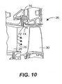
- Fig. 10 is a sectional view of a second alternative embodiment of a turbine section cooling and parasitic leakage system constructed in accordance with the teachings of the disclosure;
- Fig. 11 is a sectional view of a third alternative embodiment of a turbine section cooling and parasitic leakage system constructed in accordance with the teachings of the disclosure; and
- Fig. 12 is an enlarged sectional view of the inset portion of Fig. 11.
-
- While the following disclosure is susceptible to various modifications and alternative constructions, certain illustrative embodiments thereof have been shown in the drawings and will be described below in detail. It should be understood, however, that there is no intention to limit the disclosure to the specific forms disclosed, but on the contrary, the intention is to cover all modifications, alternative constructions, and equivalents falling within the scope of the disclosure as defined by the appended claims.
- Referring now to the drawings, and with specific reference to Fig. 1, a gas turbine engine constructed in accordance with the teachings of the disclosure is generally referred to by
reference numeral 20. As one with ordinary skill in the art will readily recognize, thegas turbine engine 20 includes acompressor section 22, acombustion section 24, and aturbine section 26. Generally, ambient air is compressed withincompressor section 22, and directed tocombustion section 24 where it is combined with fuel and ignited. The hot combustion gases resulting from ignition are then directed to theturbine section 26 and cause the turbine section to rotate and exhaust air at extremely high velocities. - The
turbine section 26 includes a plurality ofstator vanes 28 intermeshed with a plurality ofrotor blades 30. Thestator vanes 28 are fixedly mounted tocasing 32 and extend radially inwardly, whereas therotor blades 30 are mounted to arotatable rotor 34 and extend radially outwardly from arotatable shaft 36. Combustion gases exiting thecombustion section 24 are directed by the shape and angle of the turbine vanes 28 so as to impart force against therotor blades 30 thus causing therotor 34 andshaft 36 to rotate. - However, as opposed to conventional gas turbine engines wherein the primary fluid flow or gas flow path extends in the general direction of
arrow 38, and parasitic leakage air is directed into theturbine section 26 along a direction substantially transverse toarrow 38 the present disclosure teaches a turbine section cooling system and method for directing parasitic leakage air into theturbine section 26 in a direction substantially similar togas flow path 38 as indicated by arrow 39 (See Fig. 3). A number of specific structures are disclosed and described below which enable the parasitic leakage air, also referred to as secondary fluid flow and cooling air, to be so introduced to theturbine section 26. In doing so, not only is theturbine section 26 adequately cooled, but it is cooled without substantially effecting the efficiency of the engine. - Referring to Figs. 2 and 3, in a first embodiment, parasitic leakage is introduced to the
turbine section 26 along a radiallycentral plenum 40 substantially coincident withshaft 36 before being directed radially outwardly alongpath 41 through apertures 42. Thecentral plenum 40,path 41, and apertures 42 combine to form assecondary flow cavity 43. Fig. 3 indicates the direction of such parasitic leakage air flow through thecavity 43. In this first embodiment, the parasitic leakage air is able to be introduced substantially along the direction ofgas flow path 38 due to the provision of a plurality of fluid flowdirectional modifiers 44 provided proximate a trailingedge 45 of theturbine vanes 28. More specifically, in this embodiment, the fluid flowdirectional modifiers 44 are provided in the form of turning foils 44, wherein each turningfoil 44 is provided with an arcuate surface 46 (Fig. 5) which encourages the parasitic leakage air exiting through thesecondary flow cavity 43 to be turned so as to be substantially parallel to thegas flow path 38. As a result, the parasitic leakage air not only is able to cool theturbine section 26 to a degree sufficient to protect the hardware of theturbine section 26, but is also able to do so without substantially degrading the performance characteristics of theengine 20. In alternative embodiments it is to be understood that a single fluid flow directional modifier could be prescribed. - As for the actual construction of the turning foils 44, the turning foils can be cast directly into the
turbine vanes 28 or may be separately fabricated and welded and/or brazed onto thevanes 28. Figs. 4 and 5 depict thefoils 44 extending directly from awall 47 forming the trailingedge 45 of theturbine vane 28. The foils 44 may work in concert with a discourager orlip 48 extending from a leadingedge 49 of theturbine blade 30 to form thelabyrinthine path 41 as shown best in Fig. 3. In so doing, the parasitic leakage air is encouraged to enter theturbine 26 in the desired direction. - Computer models depicted in Figs. 6A and 6B, as well as Figs. 7A and 7B, illustrate the substantial advantages gained by the teachings of the present disclosure. First with respect to Figs 6A and 6B, they depict a prior art secondary cooling and
parasitic leakage system 50 wherein parasitic leakage air is directed radially outwardly and thus transverse to the direction of gas flow in a typical gas turbine engine. As a result, as best depicted in Fig. 6B, substantial recirculation represented byarea 51 is generated within theturbine section 26 thereby substantially slowing overall gas flow within theturbine section 26 and thus substantially degrading engine performance. Conversely, as indicated in Fig. 7A and 7B, thesecondary flow cavity 43 of the present disclosure introduces the cooling air substantially in the direction of thegas flow path 38 thereby providing the desired cooling characteristics without substantially effecting engine performance. In fact, in the computer model of Fig. 7B, it will be noted that the area ofrecirculation 52 is substantially smaller than that depicted in Fig. 6B. - Turning now to Figs. 8 and 9, an alternative construction of a turbine section cooling system constructed in accordance with the teachings of the disclosure is generally referred to by
reference numeral 53. As with the first embodiment, the second embodiment of the present disclosure is generally concerned with directing cooling air into theturbine section 26 of theengine 20 without substantially degrading engine performance. In this embodiment, it is able to do so by using a plurality of fluid flow directional modifiers in the form of turningholes 54 as opposed to a plurality of turning foils 44 as with the first embodiment. More specifically, as depicted in Figs. 8 and 9, ashroud 56 may be provided radially inwardly of aturbine vane wall 58 with the plurality of turningholes 54 being provided therebetween and separated by a plurality ofinternal partitions 60. In so doing, it can be seen that parasitic leakage air is directed through thesecondary flow cavity 43 along afirst plenum 62 before being directed through asecond plenum 64 and ultimately through the plurality of turning holes 54. By doing this, the air exiting from the turning holes 54 alongpath 65 is substantially aligned with the overallgas flow path 66 of theengine 20. It is to be understood that in addition to the structure set forth as indicated above, the plurality of turningholes 54 may be alternatively fabricated as by drilling, milling, or any other conventional method known to one of ordinary skill in the art of gas turbine engines. Moreover, grooves or the like, as opposed to fully encircled holes, may be machined into the structure for the same purpose. - In a still further embodiment depicted in Fig. 10, the cooling and parasitic leakage air may be directed radially inwardly as opposed to the previously identified embodiments wherein the parasitic leakage air is directed radially outwardly into the
turbine section 26. In so doing, air may be directed along an outerannular plenum 70 with a plurality of fluid flowdirectional modifiers 72 being provided at a radially outwardly disposed section of theturbine section 26.Such modifiers 72 may be provided in the form of turning foils, turning holes, grooves or other embodiments indicated or suggested above. Importantly, however, it will be noted that the secondary fluid flow of the parasitic leakage air generated by this alternative embodiment is directed into theturbine section 26 along anarrow 74 which is substantially similar to the primary fluid flow of the combustion gases as indicated byarrow 76. Accordingly, the parasitic leakage air is provided within theturbine section 26 without substantial degradation in engine performance as with the previously identified embodiments. - Another embodiment of a cooling and parasitic
leakage air system 100 constructed in accordance with the teachings of the disclosure is depicted in Figs. 11 and 12. As depicted therein, cooling and parasitic leakage air is directed along secondaryair flow cavity 101 before being directed into theturbine section 102 in the direction ofarrow 104. In accordance with the teachings of the disclosure, such secondary air flow is in substantial alignment with theprimary fluid flow 106 of the gas flow path through the turbine section. In so doing, theturbine section 102 is able to be cooled without detrimentally affecting the efficiency of the engine. Thesystem 100 may include a fluid flow direction modifier in the form of aturning hole 108 provided in aheat shield 110. Theturning hole 108 is provided at an angle resulting in the desiredsecondary cooling flow 104. - Not only is the cooling and parasitic leakage air directed into the
turbine section 102 in substantial alignment with theprimary fluid flow 106, but in such an embodiment the parasitic leakage air is accelerated into theturbine section 102 to further facilitate cooling. It is able to do so through the provision of aseal 112 within thesecondary flow cavity 101, specificallychamber 114, which creates a pressure drop across the turninghole 108. - From the foregoing, one of ordinary skill in the art will readily recognize that the teachings of the disclosure can be used to fabricate a gas turbine engine having improved secondary cooling capability to keep the turbine section of the gas turbine engine within optimal operating temperature parameters, while at the same time not substantially degrading engine performance. Engines constructed in accordance with the teachings of the disclosure are able to do so by ensuring that the parasitic leakage and cooling air are introduced to the turbine section in a direction substantially similar to the overall gas flow path therethrough.
Claims (18)
- A gas turbine engine (20),
comprising:a compressor section (22);a combustion section (24) downstream of the compressor section (22);a turbine section (26) downstream of the combustion section (24);an axial flow plenum extending through the engine, the axial flow plenum having at least one outlet fluidically coupled to the turbine section (26); andat least one fluid flow directional modifier (44; 54; 72; 108) disposed proximate the axial flow plenum. - The gas turbine engine of claim 1, wherein the fluid flow directional
modifier (44; 54; 72; 108) encourages parasitic leakage air to be introduced into the turbine section (26) in a direction substantially aligned with an overall combustion gas flow path through the turbine section. - A gas turbine engine (20), comprising:a compressor section (22) injecting ambient air and exhausting compressed air;a combustion section (24) downstream of the compressor section (22) and receiving the compressed air, the combustion section (24) introducing fuel to the compressed air and igniting the fuel and air to result in combustion gases;a turbine section (26) downstream of the combustion section (22), combustion gases traversing from the combustion section (22) through the turbine section (26) along a combustion gas flow path; anda turbine section cooling and parasitic leakage system (50) proximate the turbine section (26), the turbine section cooling system directing cooling and parasitic leakage air into the turbine section (26) substantially in the direction of the combustion gas flow path.
- The gas turbine engine of claim 3, wherein the turbine section cooling and parasitic leakage system directs cooling and parasitic leakage air circumferentially through the turbine section (26).
- The gas turbine engine of claim 3 or 4, wherein the turbine section cooling and parasitic leakage system includes a fluid flow directional modifier (44; 54; 72; 108).
- The gas turbine engine of any of claims 1, 2 or 5, wherein the fluid flow directional modifier is a turning foil (44).
- The gas turbine engine of any of claims 1, 2 or 5, wherein the fluid flow directional modifier is a turning hole ((54).
- The gas turbine engine of any of claims 1, 2 or 5, wherein the fluid flow directional modifier is a turning groove.
- The gas turbine engine of any of claims 1, 2 or 5 to 8, wherein the fluid flow directional modifier is radially inward of the turbine section (26).
- The gas turbine engine of any of claims 1, 2 or 5 to 8, wherein the fluid flow directional modifier is radially outward of the turbine section (26).
- The gas turbine engine of any of claims 1, 2 or 5 to 8, wherein the fluid flow directional modifier directs fluid radially inwardly.
- The gas turbine engine of any of claims 1, 2 or 5 to 8, wherein the fluid flow directional modifier directs fluid radially outwardly.
- A method of operating a gas turbine engine (20), comprising:compressing air in a compressor section (22) of the gas turbine engine;directing the compressed air into a combustion section (24) of the gas turbine engine;injecting fuel into the combustion section (24) of the gas turbine engine thereby igniting the fuel and compressed air to create combustion gases;directing the combustion gases from the combustion section (24) into a turbine section (26) of the gas turbine engine along a combustion gas flow path; andintroducing cooling and parasitic leakage air into the turbine section substantially in the direction of the combustion gas flow path
- The method of claim 13, wherein the cooling and parasitic leakage air is introduced from a position radially inward of the turbine section (26).
- The method of claim 13, wherein the cooling and parasitic leakage air is introduced from a position radially outward of the turbine section (26).
- The method of any of claims 13 to 15, wherein the cooling and parasitic leakage air is introduced using turning foils (44).
- The method of any of claims 13 to 15, wherein the cooling and parasitic leakage air is introduced using turning holes (54).
- The method of any of claims 13 to 15, wherein the cooling and parasitic leakage air is introduced using turning grooves.
Applications Claiming Priority (2)
| Application Number | Priority Date | Filing Date | Title |
|---|---|---|---|
| US10/813,520 US7114339B2 (en) | 2004-03-30 | 2004-03-30 | Cavity on-board injection for leakage flows |
| US813520 | 2004-03-30 |
Publications (2)
| Publication Number | Publication Date |
|---|---|
| EP1582697A1 true EP1582697A1 (en) | 2005-10-05 |
| EP1582697B1 EP1582697B1 (en) | 2008-12-31 |
Family
ID=34887708
Family Applications (1)
| Application Number | Title | Priority Date | Filing Date |
|---|---|---|---|
| EP05251997A Expired - Lifetime EP1582697B1 (en) | 2004-03-30 | 2005-03-30 | Turbine cooling air injection |
Country Status (4)
| Country | Link |
|---|---|
| US (1) | US7114339B2 (en) |
| EP (1) | EP1582697B1 (en) |
| JP (1) | JP2005337236A (en) |
| DE (1) | DE602005012009D1 (en) |
Cited By (9)
| Publication number | Priority date | Publication date | Assignee | Title |
|---|---|---|---|---|
| EP2093381A1 (en) * | 2008-02-25 | 2009-08-26 | Siemens Aktiengesellschaft | Turbine blade or vane with cooled platform |
| EP2211024A1 (en) * | 2009-01-23 | 2010-07-28 | Siemens Aktiengesellschaft | A gas turbine engine |
| WO2011029420A1 (en) | 2009-09-10 | 2011-03-17 | Mtu Aero Engines Gmbh | Deflecting device for a leakage flow in a gas turbine, and gas turbine |
| FR3001492A1 (en) * | 2013-01-25 | 2014-08-01 | Snecma | Stator i.e. high pressure distributor, for e.g. single stage high pressure turbine, of turbojet engine of aircraft, has three-dimensional patterns locally creating pressure losses at inner wall of annular radially inner platform |
| WO2014114662A3 (en) * | 2013-01-23 | 2014-10-02 | Siemens Aktiengesellschaft | Seal assembly including grooves in an inner shroud in a gas turbine engine |
| WO2014143413A3 (en) * | 2013-01-23 | 2014-12-18 | Siemens Aktiengesellschaft | Seal assembly in a gas turbine engine including grooves in a radially outwardly facing side of a platform and in a inwardly facing side of an inner shroud |
| WO2014209558A1 (en) * | 2013-06-28 | 2014-12-31 | Siemens Energy, Inc. | Aft outer rim seal arrangement |
| WO2015050676A1 (en) * | 2013-10-02 | 2015-04-09 | Siemens Aktiengesellschaft | Seal assembly including grooves in an aft facing side of a platform in a gas turbine engine |
| US9181816B2 (en) | 2013-01-23 | 2015-11-10 | Siemens Aktiengesellschaft | Seal assembly including grooves in an aft facing side of a platform in a gas turbine engine |
Families Citing this family (38)
| Publication number | Priority date | Publication date | Assignee | Title |
|---|---|---|---|---|
| CN101832154B (en) * | 2009-03-11 | 2013-03-27 | 中国科学院工程热物理研究所 | Method for cooling air film of turbine blade of aircraft engine |
| US8312729B2 (en) * | 2009-09-21 | 2012-11-20 | Honeywell International Inc. | Flow discouraging systems and gas turbine engines |
| US8616832B2 (en) * | 2009-11-30 | 2013-12-31 | Honeywell International Inc. | Turbine assemblies with impingement cooling |
| EP2453109B1 (en) * | 2010-11-15 | 2016-03-30 | Alstom Technology Ltd | Gas turbine arrangement and method for operating a gas turbine arrangement |
| US8899924B2 (en) * | 2011-06-20 | 2014-12-02 | United Technologies Corporation | Non-mechanically fastened TOBI heat shield |
| US8979481B2 (en) | 2011-10-26 | 2015-03-17 | General Electric Company | Turbine bucket angel wing features for forward cavity flow control and related method |
| US8834122B2 (en) | 2011-10-26 | 2014-09-16 | General Electric Company | Turbine bucket angel wing features for forward cavity flow control and related method |
| US9347374B2 (en) | 2012-02-27 | 2016-05-24 | United Technologies Corporation | Gas turbine engine buffer cooling system |
| US9435259B2 (en) | 2012-02-27 | 2016-09-06 | United Technologies Corporation | Gas turbine engine cooling system |
| US9038398B2 (en) | 2012-02-27 | 2015-05-26 | United Technologies Corporation | Gas turbine engine buffer cooling system |
| US9157325B2 (en) | 2012-02-27 | 2015-10-13 | United Technologies Corporation | Buffer cooling system providing gas turbine engine architecture cooling |
| US9453417B2 (en) | 2012-10-02 | 2016-09-27 | General Electric Company | Turbine intrusion loss reduction system |
| US20140196433A1 (en) * | 2012-10-17 | 2014-07-17 | United Technologies Corporation | Gas turbine engine component platform cooling |
| US9644483B2 (en) | 2013-03-01 | 2017-05-09 | General Electric Company | Turbomachine bucket having flow interrupter and related turbomachine |
| EP3052762B1 (en) | 2013-10-03 | 2021-08-04 | Raytheon Technologies Corporation | Feature to provide cooling flow to a turbine rotor disk |
| EP3084137A4 (en) * | 2013-12-19 | 2017-01-25 | United Technologies Corporation | Turbine airfoil cooling |
| EP3102808B1 (en) * | 2014-02-03 | 2020-05-06 | United Technologies Corporation | Gas turbine engine with cooling fluid composite tube |
| EP3023583A1 (en) | 2014-11-20 | 2016-05-25 | Siemens Aktiengesellschaft | Gas turbine with the cooling of the last turbine stage |
| US9771820B2 (en) | 2014-12-30 | 2017-09-26 | General Electric Company | Gas turbine sealing |
| US9765699B2 (en) | 2014-12-30 | 2017-09-19 | General Electric Company | Gas turbine sealing |
| US10619484B2 (en) | 2015-01-22 | 2020-04-14 | General Electric Company | Turbine bucket cooling |
| US10544695B2 (en) | 2015-01-22 | 2020-01-28 | General Electric Company | Turbine bucket for control of wheelspace purge air |
| US10590774B2 (en) | 2015-01-22 | 2020-03-17 | General Electric Company | Turbine bucket for control of wheelspace purge air |
| US10626727B2 (en) | 2015-01-22 | 2020-04-21 | General Electric Company | Turbine bucket for control of wheelspace purge air |
| US10815808B2 (en) | 2015-01-22 | 2020-10-27 | General Electric Company | Turbine bucket cooling |
| US10738638B2 (en) | 2015-01-22 | 2020-08-11 | General Electric Company | Rotor blade with wheel space swirlers and method for forming a rotor blade with wheel space swirlers |
| US9810087B2 (en) | 2015-06-24 | 2017-11-07 | United Technologies Corporation | Reversible blade rotor seal with protrusions |
| ES2698504T3 (en) * | 2015-07-28 | 2019-02-05 | MTU Aero Engines AG | Gas turbine |
| JP6546481B2 (en) * | 2015-08-31 | 2019-07-17 | 川崎重工業株式会社 | Exhaust diffuser |
| EP3141702A1 (en) * | 2015-09-14 | 2017-03-15 | Siemens Aktiengesellschaft | Gas turbine guide vane segment and method of manufacturing |
| DE102015224375A1 (en) * | 2015-12-04 | 2017-06-08 | Mtu Aero Engines Gmbh | Method of testing a blade unit |
| DE102016217320A1 (en) * | 2016-09-12 | 2018-03-15 | Siemens Aktiengesellschaft | Gas turbine with separate cooling for turbine and exhaust housing |
| CN106870160B (en) * | 2017-04-09 | 2018-02-23 | 中国科学院工程热物理研究所 | A kind of engine thermal end structure |
| BE1025961B1 (en) * | 2018-01-30 | 2019-08-28 | Safran Aero Boosters S.A. | ANNULAR PASSAGE BETWEEN A VIROLE AND A ROTORIC PLATFORM OF TURBOMACHINE |
| US11215063B2 (en) | 2019-10-10 | 2022-01-04 | General Electric Company | Seal assembly for chute gap leakage reduction in a gas turbine |
| IT202000006439A1 (en) * | 2020-03-26 | 2021-09-26 | Ge Avio Srl | METHOD AND APPARATUS FOR COOLING A PORTION OF A COUNTER-ROTARY TURBINE ENGINE |
| JP7284737B2 (en) * | 2020-08-06 | 2023-05-31 | 三菱重工業株式会社 | gas turbine vane |
| KR102525225B1 (en) * | 2021-03-12 | 2023-04-24 | 두산에너빌리티 주식회사 | Turbo-machine |
Citations (6)
| Publication number | Priority date | Publication date | Assignee | Title |
|---|---|---|---|---|
| US3635586A (en) * | 1970-04-06 | 1972-01-18 | Rolls Royce | Method and apparatus for turbine blade cooling |
| US4311431A (en) * | 1978-11-08 | 1982-01-19 | Teledyne Industries, Inc. | Turbine engine with shroud cooling means |
| WO1982001033A1 (en) * | 1980-09-24 | 1982-04-01 | K Karstensen | Turbine cooling system |
| US4348157A (en) * | 1978-10-26 | 1982-09-07 | Rolls-Royce Limited | Air cooled turbine for a gas turbine engine |
| EP0940562A2 (en) * | 1998-03-03 | 1999-09-08 | Mitsubishi Heavy Industries, Ltd. | Gas turbine |
| EP1074694A2 (en) * | 1999-08-04 | 2001-02-07 | General Electric Company | Apparatus and methods for cooling rotary components in a turbine |
Family Cites Families (16)
| Publication number | Priority date | Publication date | Assignee | Title |
|---|---|---|---|---|
| US2603453A (en) * | 1946-09-11 | 1952-07-15 | Curtiss Wright Corp | Cooling means for turbines |
| US3565545A (en) * | 1969-01-29 | 1971-02-23 | Melvin Bobo | Cooling of turbine rotors in gas turbine engines |
| BE755567A (en) * | 1969-12-01 | 1971-02-15 | Gen Electric | FIXED VANE STRUCTURE, FOR GAS TURBINE ENGINE AND ASSOCIATED TEMPERATURE ADJUSTMENT ARRANGEMENT |
| US3609057A (en) * | 1970-06-15 | 1971-09-28 | United Aircraft Corp | Turbine coolant flow system |
| US3670497A (en) * | 1970-09-02 | 1972-06-20 | United Aircraft Corp | Combustion chamber support |
| US3742705A (en) * | 1970-12-28 | 1973-07-03 | United Aircraft Corp | Thermal response shroud for rotating body |
| US3965066A (en) * | 1974-03-15 | 1976-06-22 | General Electric Company | Combustor-turbine nozzle interconnection |
| US5252026A (en) * | 1993-01-12 | 1993-10-12 | General Electric Company | Gas turbine engine nozzle |
| US5402636A (en) * | 1993-12-06 | 1995-04-04 | United Technologies Corporation | Anti-contamination thrust balancing system for gas turbine engines |
| US5759012A (en) * | 1996-12-13 | 1998-06-02 | Caterpillar Inc. | Turbine disc ingress prevention method and apparatus |
| US6077035A (en) * | 1998-03-27 | 2000-06-20 | Pratt & Whitney Canada Corp. | Deflector for controlling entry of cooling air leakage into the gaspath of a gas turbine engine |
| US6722138B2 (en) * | 2000-12-13 | 2004-04-20 | United Technologies Corporation | Vane platform trailing edge cooling |
| DE10064265A1 (en) * | 2000-12-22 | 2002-07-04 | Alstom Switzerland Ltd | Device and method for cooling a platform of a turbine blade |
| US6481959B1 (en) * | 2001-04-26 | 2002-11-19 | Honeywell International, Inc. | Gas turbine disk cavity ingestion inhibitor |
| US6761529B2 (en) * | 2002-07-25 | 2004-07-13 | Mitshubishi Heavy Industries, Ltd. | Cooling structure of stationary blade, and gas turbine |
| US6945749B2 (en) * | 2003-09-12 | 2005-09-20 | Siemens Westinghouse Power Corporation | Turbine blade platform cooling system |
-
2004
- 2004-03-30 US US10/813,520 patent/US7114339B2/en not_active Expired - Lifetime
-
2005
- 2005-03-15 JP JP2005072147A patent/JP2005337236A/en active Pending
- 2005-03-30 DE DE602005012009T patent/DE602005012009D1/en not_active Expired - Lifetime
- 2005-03-30 EP EP05251997A patent/EP1582697B1/en not_active Expired - Lifetime
Patent Citations (6)
| Publication number | Priority date | Publication date | Assignee | Title |
|---|---|---|---|---|
| US3635586A (en) * | 1970-04-06 | 1972-01-18 | Rolls Royce | Method and apparatus for turbine blade cooling |
| US4348157A (en) * | 1978-10-26 | 1982-09-07 | Rolls-Royce Limited | Air cooled turbine for a gas turbine engine |
| US4311431A (en) * | 1978-11-08 | 1982-01-19 | Teledyne Industries, Inc. | Turbine engine with shroud cooling means |
| WO1982001033A1 (en) * | 1980-09-24 | 1982-04-01 | K Karstensen | Turbine cooling system |
| EP0940562A2 (en) * | 1998-03-03 | 1999-09-08 | Mitsubishi Heavy Industries, Ltd. | Gas turbine |
| EP1074694A2 (en) * | 1999-08-04 | 2001-02-07 | General Electric Company | Apparatus and methods for cooling rotary components in a turbine |
Cited By (21)
| Publication number | Priority date | Publication date | Assignee | Title |
|---|---|---|---|---|
| EP2093381A1 (en) * | 2008-02-25 | 2009-08-26 | Siemens Aktiengesellschaft | Turbine blade or vane with cooled platform |
| WO2009106464A1 (en) * | 2008-02-25 | 2009-09-03 | Siemens Aktiengesellschaft | Turbine blade or vane with cooled platform |
| EP2211024A1 (en) * | 2009-01-23 | 2010-07-28 | Siemens Aktiengesellschaft | A gas turbine engine |
| WO2010084141A1 (en) * | 2009-01-23 | 2010-07-29 | Siemens Aktiengesellschaft | A gas turbine engine |
| US8790073B2 (en) | 2009-01-23 | 2014-07-29 | Siemens Aktiengesellschaft | Gas turbine engine including a stator vane for directing hot combustion gases onto rotor blades |
| CN102405331B (en) * | 2009-01-23 | 2015-08-26 | 西门子公司 | Gas turbine engine |
| WO2011029420A1 (en) | 2009-09-10 | 2011-03-17 | Mtu Aero Engines Gmbh | Deflecting device for a leakage flow in a gas turbine, and gas turbine |
| RU2650228C2 (en) * | 2013-01-23 | 2018-04-11 | Сименс Акциенгезелльшафт | Seal assembly including for gas turbine engine |
| WO2014143413A3 (en) * | 2013-01-23 | 2014-12-18 | Siemens Aktiengesellschaft | Seal assembly in a gas turbine engine including grooves in a radially outwardly facing side of a platform and in a inwardly facing side of an inner shroud |
| WO2014114662A3 (en) * | 2013-01-23 | 2014-10-02 | Siemens Aktiengesellschaft | Seal assembly including grooves in an inner shroud in a gas turbine engine |
| RU2640144C2 (en) * | 2013-01-23 | 2017-12-26 | Сименс Акциенгезелльшафт | Seal assembly for gas turbine engine including grooves in inner band |
| US9039357B2 (en) | 2013-01-23 | 2015-05-26 | Siemens Aktiengesellschaft | Seal assembly including grooves in a radially outwardly facing side of a platform in a gas turbine engine |
| US9068513B2 (en) | 2013-01-23 | 2015-06-30 | Siemens Aktiengesellschaft | Seal assembly including grooves in an inner shroud in a gas turbine engine |
| US9181816B2 (en) | 2013-01-23 | 2015-11-10 | Siemens Aktiengesellschaft | Seal assembly including grooves in an aft facing side of a platform in a gas turbine engine |
| FR3001492A1 (en) * | 2013-01-25 | 2014-08-01 | Snecma | Stator i.e. high pressure distributor, for e.g. single stage high pressure turbine, of turbojet engine of aircraft, has three-dimensional patterns locally creating pressure losses at inner wall of annular radially inner platform |
| CN105339595A (en) * | 2013-06-28 | 2016-02-17 | 西门子能源公司 | Aft outer rim seal arrangement |
| CN105339595B (en) * | 2013-06-28 | 2018-03-27 | 西门子能源公司 | Tail outer edge seal |
| WO2014209558A1 (en) * | 2013-06-28 | 2014-12-31 | Siemens Energy, Inc. | Aft outer rim seal arrangement |
| CN105765169A (en) * | 2013-10-02 | 2016-07-13 | 西门子公司 | Seal assembly including grooves in an aft facing side of a platform in a gas turbine engine |
| WO2015050676A1 (en) * | 2013-10-02 | 2015-04-09 | Siemens Aktiengesellschaft | Seal assembly including grooves in an aft facing side of a platform in a gas turbine engine |
| CN105765169B (en) * | 2013-10-02 | 2019-05-07 | 西门子公司 | A seal assembly in a gas turbine engine including a groove in the rear facing side of the platform |
Also Published As
| Publication number | Publication date |
|---|---|
| US20050217277A1 (en) | 2005-10-06 |
| EP1582697B1 (en) | 2008-12-31 |
| US7114339B2 (en) | 2006-10-03 |
| DE602005012009D1 (en) | 2009-02-12 |
| JP2005337236A (en) | 2005-12-08 |
Similar Documents
| Publication | Publication Date | Title |
|---|---|---|
| US7114339B2 (en) | Cavity on-board injection for leakage flows | |
| CN108138654B (en) | Turboprop engine assembly with combined engine and cooled exhaust | |
| CN109668174B (en) | Trapped vortex combustor for gas turbine engine and method of operation | |
| US7303372B2 (en) | Methods and apparatus for cooling combustion turbine engine components | |
| EP1512843B1 (en) | Method of assembling a gas turbine engine and rotor assembly | |
| EP2489937B1 (en) | Combustor assembly for use in a turbine engine and methods of fabricating same | |
| US10495309B2 (en) | Surface contouring of a flowpath wall of a gas turbine engine | |
| EP3190340A1 (en) | Cooled combustor for a gas turbine engine | |
| CN106958463A (en) | The gas-turbine unit of nozzle segment with cooling | |
| EP3428398A1 (en) | Airfoil and corresponding method of cooling a tip rail | |
| US10458291B2 (en) | Cover plate for a component of a gas turbine engine | |
| CA2944392A1 (en) | Turbine blade | |
| US20130028735A1 (en) | Blade cooling and sealing system | |
| US20180156044A1 (en) | Engine component with flow enhancer | |
| US10830053B2 (en) | Engine component cooling hole | |
| EP3431710A1 (en) | Shield for a turbine engine airfoil | |
| CA2956346A1 (en) | Turbine engine airfoil with cooling | |
| EP3246522B1 (en) | Internal cooling of stator vanes | |
| EP2631431B1 (en) | Aerofoil cooling arrangement | |
| US10851673B2 (en) | Turbine stator, turbine, and gas turbine including the same |
Legal Events
| Date | Code | Title | Description |
|---|---|---|---|
| PUAI | Public reference made under article 153(3) epc to a published international application that has entered the european phase |
Free format text: ORIGINAL CODE: 0009012 |
|
| AK | Designated contracting states |
Kind code of ref document: A1 Designated state(s): AT BE BG CH CY CZ DE DK EE ES FI FR GB GR HU IE IS IT LI LT LU MC NL PL PT RO SE SI SK TR |
|
| AX | Request for extension of the european patent |
Extension state: AL BA HR LV MK YU |
|
| RTI1 | Title (correction) |
Free format text: TURBINE COOLING AIR INJECTION |
|
| 17P | Request for examination filed |
Effective date: 20051005 |
|
| AKX | Designation fees paid |
Designated state(s): DE FR GB |
|
| GRAP | Despatch of communication of intention to grant a patent |
Free format text: ORIGINAL CODE: EPIDOSNIGR1 |
|
| GRAS | Grant fee paid |
Free format text: ORIGINAL CODE: EPIDOSNIGR3 |
|
| GRAA | (expected) grant |
Free format text: ORIGINAL CODE: 0009210 |
|
| AK | Designated contracting states |
Kind code of ref document: B1 Designated state(s): DE FR GB |
|
| REG | Reference to a national code |
Ref country code: GB Ref legal event code: FG4D |
|
| REF | Corresponds to: |
Ref document number: 602005012009 Country of ref document: DE Date of ref document: 20090212 Kind code of ref document: P |
|
| PLBE | No opposition filed within time limit |
Free format text: ORIGINAL CODE: 0009261 |
|
| STAA | Information on the status of an ep patent application or granted ep patent |
Free format text: STATUS: NO OPPOSITION FILED WITHIN TIME LIMIT |
|
| 26N | No opposition filed |
Effective date: 20091001 |
|
| REG | Reference to a national code |
Ref country code: FR Ref legal event code: ST Effective date: 20091130 |
|
| PG25 | Lapsed in a contracting state [announced via postgrant information from national office to epo] |
Ref country code: FR Free format text: LAPSE BECAUSE OF NON-PAYMENT OF DUE FEES Effective date: 20091123 |
|
| REG | Reference to a national code |
Ref country code: DE Ref legal event code: R082 Ref document number: 602005012009 Country of ref document: DE Representative=s name: SCHMITT-NILSON SCHRAUD WAIBEL WOHLFROM PATENTA, DE |
|
| REG | Reference to a national code |
Ref country code: DE Ref legal event code: R082 Ref document number: 602005012009 Country of ref document: DE Representative=s name: SCHMITT-NILSON SCHRAUD WAIBEL WOHLFROM PATENTA, DE Ref country code: DE Ref legal event code: R081 Ref document number: 602005012009 Country of ref document: DE Owner name: UNITED TECHNOLOGIES CORP. (N.D.GES.D. STAATES , US Free format text: FORMER OWNER: UNITED TECHNOLOGIES CORP., HARTFORD, CONN., US |
|
| PGFP | Annual fee paid to national office [announced via postgrant information from national office to epo] |
Ref country code: DE Payment date: 20200218 Year of fee payment: 16 |
|
| REG | Reference to a national code |
Ref country code: DE Ref legal event code: R119 Ref document number: 602005012009 Country of ref document: DE |
|
| PG25 | Lapsed in a contracting state [announced via postgrant information from national office to epo] |
Ref country code: DE Free format text: LAPSE BECAUSE OF NON-PAYMENT OF DUE FEES Effective date: 20211001 |
|
| PGFP | Annual fee paid to national office [announced via postgrant information from national office to epo] |
Ref country code: GB Payment date: 20240221 Year of fee payment: 20 |
|
| REG | Reference to a national code |
Ref country code: GB Ref legal event code: PE20 Expiry date: 20250329 |
|
| PG25 | Lapsed in a contracting state [announced via postgrant information from national office to epo] |
Ref country code: GB Free format text: LAPSE BECAUSE OF EXPIRATION OF PROTECTION Effective date: 20250329 |