EP3246522B1 - Internal cooling of stator vanes - Google Patents
Internal cooling of stator vanes Download PDFInfo
- Publication number
- EP3246522B1 EP3246522B1 EP17172075.8A EP17172075A EP3246522B1 EP 3246522 B1 EP3246522 B1 EP 3246522B1 EP 17172075 A EP17172075 A EP 17172075A EP 3246522 B1 EP3246522 B1 EP 3246522B1
- Authority
- EP
- European Patent Office
- Prior art keywords
- cooling
- passage
- stator
- inlet
- leading edge
- Prior art date
- Legal status (The legal status is an assumption and is not a legal conclusion. Google has not performed a legal analysis and makes no representation as to the accuracy of the status listed.)
- Active
Links
- 238000001816 cooling Methods 0.000 title claims description 99
- 238000000034 method Methods 0.000 claims description 8
- 239000012809 cooling fluid Substances 0.000 claims description 5
- 238000005219 brazing Methods 0.000 claims description 3
- 238000003466 welding Methods 0.000 claims description 3
- 239000007789 gas Substances 0.000 description 16
- 239000000567 combustion gas Substances 0.000 description 4
- 230000003750 conditioning effect Effects 0.000 description 3
- 238000005266 casting Methods 0.000 description 2
- 239000000919 ceramic Substances 0.000 description 2
- 238000005553 drilling Methods 0.000 description 2
- 239000000446 fuel Substances 0.000 description 1
- 239000002184 metal Substances 0.000 description 1
- 230000001141 propulsive effect Effects 0.000 description 1
Images


Classifications
-
- F—MECHANICAL ENGINEERING; LIGHTING; HEATING; WEAPONS; BLASTING
- F01—MACHINES OR ENGINES IN GENERAL; ENGINE PLANTS IN GENERAL; STEAM ENGINES
- F01D—NON-POSITIVE DISPLACEMENT MACHINES OR ENGINES, e.g. STEAM TURBINES
- F01D9/00—Stators
- F01D9/02—Nozzles; Nozzle boxes; Stator blades; Guide conduits, e.g. individual nozzles
- F01D9/04—Nozzles; Nozzle boxes; Stator blades; Guide conduits, e.g. individual nozzles forming ring or sector
- F01D9/041—Nozzles; Nozzle boxes; Stator blades; Guide conduits, e.g. individual nozzles forming ring or sector using blades
-
- F—MECHANICAL ENGINEERING; LIGHTING; HEATING; WEAPONS; BLASTING
- F01—MACHINES OR ENGINES IN GENERAL; ENGINE PLANTS IN GENERAL; STEAM ENGINES
- F01D—NON-POSITIVE DISPLACEMENT MACHINES OR ENGINES, e.g. STEAM TURBINES
- F01D9/00—Stators
- F01D9/06—Fluid supply conduits to nozzles or the like
- F01D9/065—Fluid supply or removal conduits traversing the working fluid flow, e.g. for lubrication-, cooling-, or sealing fluids
-
- F—MECHANICAL ENGINEERING; LIGHTING; HEATING; WEAPONS; BLASTING
- F01—MACHINES OR ENGINES IN GENERAL; ENGINE PLANTS IN GENERAL; STEAM ENGINES
- F01D—NON-POSITIVE DISPLACEMENT MACHINES OR ENGINES, e.g. STEAM TURBINES
- F01D5/00—Blades; Blade-carrying members; Heating, heat-insulating, cooling or antivibration means on the blades or the members
- F01D5/12—Blades
- F01D5/14—Form or construction
- F01D5/18—Hollow blades, i.e. blades with cooling or heating channels or cavities; Heating, heat-insulating or cooling means on blades
-
- F—MECHANICAL ENGINEERING; LIGHTING; HEATING; WEAPONS; BLASTING
- F05—INDEXING SCHEMES RELATING TO ENGINES OR PUMPS IN VARIOUS SUBCLASSES OF CLASSES F01-F04
- F05D—INDEXING SCHEME FOR ASPECTS RELATING TO NON-POSITIVE-DISPLACEMENT MACHINES OR ENGINES, GAS-TURBINES OR JET-PROPULSION PLANTS
- F05D2220/00—Application
- F05D2220/30—Application in turbines
- F05D2220/32—Application in turbines in gas turbines
-
- F—MECHANICAL ENGINEERING; LIGHTING; HEATING; WEAPONS; BLASTING
- F05—INDEXING SCHEMES RELATING TO ENGINES OR PUMPS IN VARIOUS SUBCLASSES OF CLASSES F01-F04
- F05D—INDEXING SCHEME FOR ASPECTS RELATING TO NON-POSITIVE-DISPLACEMENT MACHINES OR ENGINES, GAS-TURBINES OR JET-PROPULSION PLANTS
- F05D2230/00—Manufacture
- F05D2230/10—Manufacture by removing material
-
- F—MECHANICAL ENGINEERING; LIGHTING; HEATING; WEAPONS; BLASTING
- F05—INDEXING SCHEMES RELATING TO ENGINES OR PUMPS IN VARIOUS SUBCLASSES OF CLASSES F01-F04
- F05D—INDEXING SCHEME FOR ASPECTS RELATING TO NON-POSITIVE-DISPLACEMENT MACHINES OR ENGINES, GAS-TURBINES OR JET-PROPULSION PLANTS
- F05D2230/00—Manufacture
- F05D2230/20—Manufacture essentially without removing material
- F05D2230/23—Manufacture essentially without removing material by permanently joining parts together
- F05D2230/232—Manufacture essentially without removing material by permanently joining parts together by welding
- F05D2230/237—Brazing
-
- F—MECHANICAL ENGINEERING; LIGHTING; HEATING; WEAPONS; BLASTING
- F05—INDEXING SCHEMES RELATING TO ENGINES OR PUMPS IN VARIOUS SUBCLASSES OF CLASSES F01-F04
- F05D—INDEXING SCHEME FOR ASPECTS RELATING TO NON-POSITIVE-DISPLACEMENT MACHINES OR ENGINES, GAS-TURBINES OR JET-PROPULSION PLANTS
- F05D2240/00—Components
- F05D2240/10—Stators
- F05D2240/12—Fluid guiding means, e.g. vanes
- F05D2240/121—Fluid guiding means, e.g. vanes related to the leading edge of a stator vane
-
- F—MECHANICAL ENGINEERING; LIGHTING; HEATING; WEAPONS; BLASTING
- F05—INDEXING SCHEMES RELATING TO ENGINES OR PUMPS IN VARIOUS SUBCLASSES OF CLASSES F01-F04
- F05D—INDEXING SCHEME FOR ASPECTS RELATING TO NON-POSITIVE-DISPLACEMENT MACHINES OR ENGINES, GAS-TURBINES OR JET-PROPULSION PLANTS
- F05D2240/00—Components
- F05D2240/80—Platforms for stationary or moving blades
- F05D2240/81—Cooled platforms
-
- F—MECHANICAL ENGINEERING; LIGHTING; HEATING; WEAPONS; BLASTING
- F05—INDEXING SCHEMES RELATING TO ENGINES OR PUMPS IN VARIOUS SUBCLASSES OF CLASSES F01-F04
- F05D—INDEXING SCHEME FOR ASPECTS RELATING TO NON-POSITIVE-DISPLACEMENT MACHINES OR ENGINES, GAS-TURBINES OR JET-PROPULSION PLANTS
- F05D2250/00—Geometry
- F05D2250/30—Arrangement of components
- F05D2250/32—Arrangement of components according to their shape
- F05D2250/324—Arrangement of components according to their shape divergent
-
- F—MECHANICAL ENGINEERING; LIGHTING; HEATING; WEAPONS; BLASTING
- F05—INDEXING SCHEMES RELATING TO ENGINES OR PUMPS IN VARIOUS SUBCLASSES OF CLASSES F01-F04
- F05D—INDEXING SCHEME FOR ASPECTS RELATING TO NON-POSITIVE-DISPLACEMENT MACHINES OR ENGINES, GAS-TURBINES OR JET-PROPULSION PLANTS
- F05D2260/00—Function
- F05D2260/20—Heat transfer, e.g. cooling
- F05D2260/202—Heat transfer, e.g. cooling by film cooling
Definitions
- This disclosure relates to gas turbine engines, and more particularly to the provision of cooling air for components of gas turbine engines.
- Gas turbines hot section components in particular turbine vanes and blades in the turbine section of the gas turbine are configured for use within particular temperature ranges. Such components often rely on cooling airflow to maintain turbine components within this particular temperature range.
- stationary turbine vanes often have internal passages for cooling airflow to flow through, and additionally may have openings in an outer surface of the vane for cooling airflow to exit the interior of the vane structure and form a cooling film of air over the outer surface to provide the necessary thermal conditioning.
- Other components of the turbine often also require such thermal conditioning to reduce thermal gradients that would otherwise be present in the structure and which are generally undesirable. Thus, ways to increase thermal conditioning capability in the turbine are desired.
- WO 2015/026597 A1 , EP 0 392 664 A2 , GB 2 263 946 A , JP 5 905631 B1 , US 2015/184530 A1 , US 2014/023483 A1 , and EP 3 184 751 A1 each provide a stator having cooling passages therein.
- the internal cooling passages are typically formed in stator vanes through the use of ceramic cores during the casting process of the stator vanes.
- the complex geometry of the cooling passages typically prevents advantageously combining ceramic cores into a single core, which would significantly improve producibility of the stator vane. Further, as separate cores are utilized, cooling air flowed through the cooling passages is therefore fed from separate cooling airflow sources, which in many instances may not be optimal cooling air sources.
- a turbine stator for a gas turbine engine according to claim 1.
- connection passage may include a passage opening in an external surface of the stator, and a closure secured over the passage opening to prevent leakage of the cooling fluid flow through the passage opening.
- the closure may be one of a plug or a cover.
- the closure may be secured over the passage opening via welding or brazing.
- a cooling flow may be directed from the cooling flow source through the first cooling passage inlet and a first portion of the cooling flow is directed from the first cooling passage inlet through the connecting passage to the second cooling passage.
- the first portion of the cooling flow may be directed into the second cooling passage and a second portion of the cooling flow is directed into the first cooling passage.
- a closure may be secured at an opening formed at the external surface.
- the closure may be one of a plug or a cover.
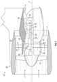
- FIG. 1 is a schematic illustration of a gas turbine engine 10.
- the gas turbine engine generally has includes fan section 12, a low pressure compressor 14, a high pressure compressor 16, a combustor 18, a high pressure turbine 20 and a low pressure turbine 22.
- the gas turbine engine 10 is circumferentially disposed about an engine centerline X.
- air is pulled into the gas turbine engine 10 by the fan section 12, pressurized by the compressors 14, 16, mixed with fuel and burned in the combustor 18.
- Hot combustion gases generated within the combustor 18 flow through high and low pressure turbines 20, 22, which extract energy from the hot combustion gases.
- the high pressure turbine 20 utilizes the extracted energy from the hot combustion gases to power the high pressure compressor 16 through a high speed shaft 24, and the low pressure turbine 22 utilizes the energy extracted from the hot combustion gases to power the low pressure compressor 14 and the fan section 12 through a low speed shaft 26.
- the present disclosure is not limited to the two-spool configuration described and may be utilized with other configurations, such as single-spool or three-spool configurations, or gear-driven fan configurations.
- Gas turbine engine 10 is in the form of a high bypass ratio turbine engine mounted within a nacelle or fan casing 28 which surrounds an engine casing 30 housing an engine core 32.
- a significant amount of air pressurized by the fan section 12 bypasses the engine core 32 for the generation of propulsive thrust.
- the airflow entering the fan section 12 may bypass the engine core 32 via a fan bypass passage 34 extending between the fan casing 28 and the engine casing 30 for receiving and communicating a discharge flow F1.
- the high bypass flow arrangement provides a significant amount of thrust for powering an aircraft.
- the engine casing 30 generally includes an inlet case 36, a low pressure compressor case 38, and an intermediate case 40.
- the inlet case 36 guides air to the low pressure compressor case 38, and via a splitter 42 also directs air through the fan bypass passage 34.
- the high pressure turbine 20 includes one or more high pressure turbine rotors 44 in an axially-alternating arrangement with one or more high pressure turbine (HPT) stators 46.
- the low pressure turbine 22 includes one or more low pressure turbine rotors in an axially-alternating arrangement with one or more low pressure turbine stators.
- the following description is in reference to a high pressure turbine stator 46, but one skilled in the art will readily appreciate that the disclosure provided herein may be similarly utilized in a low pressure turbine stator, or similar turbine compressor components having internal cooling passages.
- the HPT stator 46 includes a turbine vane 52 and an outer platform 54 located at a radially outboard extent of the turbine vane 52, and an inner platform 56 located at a radially inboard extent of the turbine vane 52.
- the HPT stator 46 is provided with cooling passages to distribute cooling airflow internally throughout the HPT stator 46.
- the cooling passages circulate the cooling airflow in an interior of the HPT stator 46, while in other embodiments the cooling passages communicate with film cooling holes (not shown) on the HPT stator 46 to form a cooling film one or more external surfaces of the HPT stator 46.
- At least two cooling passages are formed in the HPT stator 46, a vane leading edge cooling passage 58 extending along a vane leading edge 60, and a platform cooling passage 62 extending along the outer platform 54.
- the platform cooling passage 62 has a platform cooling inlet 64, while the vane leading edge cooling passage 58 has a leading edge cooling inlet 66. Due to the complexity of the cooling passage geometry, the vane leading edge cooling passage 58 is formed separately from the platform cooling passage 62, and the platform cooling inlet 64 is separate from the leading edge cooling inlet 66.
- a communication passage 70 is formed in the HPT stator 46.
- the communication passage 70 extends in accordance with the invention, between the leading edge cooling inlet 66 and the platform cooling inlet 64 with the leading edge cooling inlet 66 connected to the common cooling flow source 68.
- connection passage 70 is formed in the HPT stator 46 by drilling.
- the connection passage 70 is drilled by, for example, drilling through an external surface 72 of the HPT stator 46 at the platform cooling inlet 64.
- the connection passage 70 is drilled from the external surface 72, through the platform cooling inlet 64 and into the leading edge cooling inlet 66. It is to be appreciated that the forming of the connection passage 70 described herein is merely exemplary, one skilled in the art will readily appreciate that other methods may be utilized to form the connection passage 70.
- the connection passage 70 extends between the platform cooling inlet 64 and the leading edge cooling inlet 66 in a circumferential direction.
- an external surface opening 74 must be closed to prevent leakage of the cooling airflow.
- the external surface opening may be closed via a closure, such as a plug 76 that is secured in place in the external surface opening 74 by, for example, welding or brazing.
- Other means may also be used to close the external surface opening 74, such as a sheet metal cover secured over external surface opening 74 may be utilized.
- connection passage 70 allows for a HPT stator 46 casting with improved producibility, while utilizing a selected cooling flow source 68 that improves gas turbine engine 10 efficiency and durability.
Description
- This disclosure relates to gas turbine engines, and more particularly to the provision of cooling air for components of gas turbine engines.
- Gas turbines hot section components, in particular turbine vanes and blades in the turbine section of the gas turbine are configured for use within particular temperature ranges. Such components often rely on cooling airflow to maintain turbine components within this particular temperature range. For example, stationary turbine vanes often have internal passages for cooling airflow to flow through, and additionally may have openings in an outer surface of the vane for cooling airflow to exit the interior of the vane structure and form a cooling film of air over the outer surface to provide the necessary thermal conditioning. Other components of the turbine often also require such thermal conditioning to reduce thermal gradients that would otherwise be present in the structure and which are generally undesirable. Thus, ways to increase thermal conditioning capability in the turbine are desired.
WO 2015/026597 A1 ,EP 0 392 664 A2 ,GB 2 263 946 A JP 5 905631 B1 US 2015/184530 A1 ,US 2014/023483 A1 , andEP 3 184 751 A1 each provide a stator having cooling passages therein. - The internal cooling passages are typically formed in stator vanes through the use of ceramic cores during the casting process of the stator vanes. The complex geometry of the cooling passages typically prevents advantageously combining ceramic cores into a single core, which would significantly improve producibility of the stator vane. Further, as separate cores are utilized, cooling air flowed through the cooling passages is therefore fed from separate cooling airflow sources, which in many instances may not be optimal cooling air sources.
- In a first aspect, there is provided a turbine stator for a gas turbine engine according to claim 1.
- The connection passage may include a passage opening in an external surface of the stator, and a closure secured over the passage opening to prevent leakage of the cooling fluid flow through the passage opening.
- The closure may be one of a plug or a cover.
- The closure may be secured over the passage opening via welding or brazing.
- In another aspect, there is provided a gas turbine engine according to claim 4.
- In yet another embodiment, a method of cooling a stator for a gas turbine engine according to claim 5 is provided.
- A cooling flow may be directed from the cooling flow source through the first cooling passage inlet and a first portion of the cooling flow is directed from the first cooling passage inlet through the connecting passage to the second cooling passage.
- The first portion of the cooling flow may be directed into the second cooling passage and a second portion of the cooling flow is directed into the first cooling passage.
- A closure may be secured at an opening formed at the external surface.
- The closure may be one of a plug or a cover.
- The subject matter which is regarded as the present disclosure is particularly pointed out and distinctly claimed in the claims at the conclusion of the specification. The foregoing and other features, and advantages of the present disclosure are apparent from the following detailed description taken in conjunction with the accompanying drawings in which:
-
FIG. 1 illustrates a schematic cross-sectional view of an embodiment of a gas turbine engine; -
FIG. 2 illustrates a schematic cross-sectional view of an embodiment of a turbine section of a gas turbine engine; and -
FIG. 3 is a schematic view of an embodiment of a cooling flow passage arrangement for a stator vane; -
FIG. 4 is a schematic view of an embodiment of a connection passage for a cooling flow passage arrangement; and -
FIG. 4 is a schematic view of an embodiment of a connection passage for a cooling flow passage arrangement; and -
FIG. 5 is another schematic view of an embodiment of a connection passage for a cooling flow passage arrangement. -
FIG. 1 is a schematic illustration of agas turbine engine 10. The gas turbine engine generally has includesfan section 12, alow pressure compressor 14, ahigh pressure compressor 16, acombustor 18, ahigh pressure turbine 20 and alow pressure turbine 22. Thegas turbine engine 10 is circumferentially disposed about an engine centerline X. During operation, air is pulled into thegas turbine engine 10 by thefan section 12, pressurized by thecompressors combustor 18. Hot combustion gases generated within thecombustor 18 flow through high andlow pressure turbines - In a two-spool configuration, the
high pressure turbine 20 utilizes the extracted energy from the hot combustion gases to power thehigh pressure compressor 16 through ahigh speed shaft 24, and thelow pressure turbine 22 utilizes the energy extracted from the hot combustion gases to power thelow pressure compressor 14 and thefan section 12 through alow speed shaft 26. The present disclosure, however, is not limited to the two-spool configuration described and may be utilized with other configurations, such as single-spool or three-spool configurations, or gear-driven fan configurations. -
Gas turbine engine 10 is in the form of a high bypass ratio turbine engine mounted within a nacelle orfan casing 28 which surrounds anengine casing 30 housing anengine core 32. A significant amount of air pressurized by thefan section 12 bypasses theengine core 32 for the generation of propulsive thrust. The airflow entering thefan section 12 may bypass theengine core 32 via afan bypass passage 34 extending between thefan casing 28 and theengine casing 30 for receiving and communicating a discharge flow F1. The high bypass flow arrangement provides a significant amount of thrust for powering an aircraft. - The
engine casing 30 generally includes aninlet case 36, a lowpressure compressor case 38, and anintermediate case 40. Theinlet case 36 guides air to the lowpressure compressor case 38, and via asplitter 42 also directs air through thefan bypass passage 34. - Referring now to
FIG. 2 , thehigh pressure turbine 20 includes one or more highpressure turbine rotors 44 in an axially-alternating arrangement with one or more high pressure turbine (HPT)stators 46. Similarly, thelow pressure turbine 22 includes one or more low pressure turbine rotors in an axially-alternating arrangement with one or more low pressure turbine stators. The following description is in reference to a highpressure turbine stator 46, but one skilled in the art will readily appreciate that the disclosure provided herein may be similarly utilized in a low pressure turbine stator, or similar turbine compressor components having internal cooling passages. The HPTstator 46 includes aturbine vane 52 and anouter platform 54 located at a radially outboard extent of theturbine vane 52, and aninner platform 56 located at a radially inboard extent of theturbine vane 52. - Referring now to
FIG. 3 , because of high operating temperatures in this portion of thegas turbine engine 10, the HPTstator 46 is provided with cooling passages to distribute cooling airflow internally throughout theHPT stator 46. In some embodiments, the cooling passages circulate the cooling airflow in an interior of theHPT stator 46, while in other embodiments the cooling passages communicate with film cooling holes (not shown) on theHPT stator 46 to form a cooling film one or more external surfaces of theHPT stator 46. - According to the invention, as shown in
FIG. 3 , at least two cooling passages are formed in theHPT stator 46, a vane leadingedge cooling passage 58 extending along avane leading edge 60, and aplatform cooling passage 62 extending along theouter platform 54. Theplatform cooling passage 62 has aplatform cooling inlet 64, while the vane leadingedge cooling passage 58 has a leadingedge cooling inlet 66. Due to the complexity of the cooling passage geometry, the vane leadingedge cooling passage 58 is formed separately from theplatform cooling passage 62, and theplatform cooling inlet 64 is separate from the leadingedge cooling inlet 66. - Referring now to
FIG. 4 , in accordance with the invention, it is desired to feed the cooling airflow to theplatform cooling inlet 64 and the leadingedge cooling inlet 66 from a commoncooling flow source 68. Thecooling flow source 68 is located at a radially outboardmost practicable location, where the cooling airflow has a relatively low temperature and high pressure, relative to radially inboard locations. To feed theplatform cooling inlet 64 and the leadingedge cooling inlet 66 from the commoncooling flow source 68, acommunication passage 70 is formed in theHPT stator 46. Thecommunication passage 70 extends in accordance with the invention, between the leadingedge cooling inlet 66 and theplatform cooling inlet 64 with the leadingedge cooling inlet 66 connected to the commoncooling flow source 68. - In some embodiments, the
connection passage 70 is formed in theHPT stator 46 by drilling. Theconnection passage 70 is drilled by, for example, drilling through anexternal surface 72 of theHPT stator 46 at theplatform cooling inlet 64. Theconnection passage 70 is drilled from theexternal surface 72, through theplatform cooling inlet 64 and into the leadingedge cooling inlet 66. It is to be appreciated that the forming of theconnection passage 70 described herein is merely exemplary, one skilled in the art will readily appreciate that other methods may be utilized to form theconnection passage 70. In some embodiments, theconnection passage 70 extends between theplatform cooling inlet 64 and the leadingedge cooling inlet 66 in a circumferential direction. - Referring now to
FIG. 5 , once theconnection passage 70 is formed, anexternal surface opening 74 must be closed to prevent leakage of the cooling airflow. The external surface opening may be closed via a closure, such as aplug 76 that is secured in place in the external surface opening 74 by, for example, welding or brazing. Other means may also be used to close the external surface opening 74, such as a sheet metal cover secured over external surface opening 74 may be utilized. - Utilizing the
connection passage 70 allows for aHPT stator 46 casting with improved producibility, while utilizing a selectedcooling flow source 68 that improvesgas turbine engine 10 efficiency and durability. - While the present disclosure has been described in detail in connection with only a limited number of embodiments, it should be readily understood that the present disclosure is not limited to such disclosed embodiments. Rather, the present disclosure is not to be seen as limited by the foregoing description, but is only limited by the scope of the appended claims.
Claims (9)
- A turbine stator (46) for a gas turbine engine (10) comprising:a vane (52);an outer vane platform (54) located at a radially outboard extent of the vane;a first cooling passage (58) disposed at the stator to provide a cooling fluid flow to a first portion of the stator, the first cooling passage being a vane leading edge cooling passage (58) of the vane (52), and having a leading edge cooling inlet (66);a second cooling passage (62) disposed at the stator to provide a cooling fluid flow to a second portion of the stator, the second cooling passage being a platform cooling passage (62) of the vane (52), and having a platform cooling inlet (64);a connection passage (70) extending at least partially through the stator to connect said leading edge cooling inlet (66) of the first cooling passage (58) to the platform cooling inlet (64) of the second cooling passage (62); anda common cooling flow source (68) from which the cooling fluid flow is directed into the first cooling passage (58) and the second cooling passage (62) via said leading edge cooling inlet (66);wherein the leading edge cooling inlet (66) extends radially outwardly to a greater extent than the platform cooling inlet (64).
- The stator of claim 1, wherein the connection passage includes a passage opening (74) in an external surface of the stator, and a closure (76) secured over the passage opening to prevent leakage of the cooling fluid flow through the passage opening, wherein the closure is one of a plug or a cover.
- The stator of claim 1 or 2, wherein the closure (76) is secured over the passage opening (74) via welding or brazing.
- A gas turbine engine, comprising:a turbine rotor (44); anda turbine stator (46) being the turbine stator of any preceding claim.
- A method of cooling the turbine stator for a gas turbine engine according to claim 1, the method comprising:
connecting the leading edge cooling inlet (66) to a cooling flow source (68). - The method of claim 5, further comprising:directing a cooling flow from the cooling flow source through the leading edge cooling inlet (66); anddirecting a first portion of the cooling flow from the leading edge cooling inlet (66) through the connecting passage (70) to the second cooling passage (62).
- The method of claim 6, further comprising:directing the first portion of the cooling flow into the second cooling passage (62); anddirecting a second portion of the cooling flow into the first cooling passage (58).
- The method of claim 5, further comprising securing a closure (76) at an opening (74) formed at the external surface.
- The method of claim 8, wherein the closure (76) is one of a plug or a cover.
Applications Claiming Priority (1)
| Application Number | Priority Date | Filing Date | Title |
|---|---|---|---|
| US15/159,935 US10352182B2 (en) | 2016-05-20 | 2016-05-20 | Internal cooling of stator vanes |
Publications (2)
| Publication Number | Publication Date |
|---|---|
| EP3246522A1 EP3246522A1 (en) | 2017-11-22 |
| EP3246522B1 true EP3246522B1 (en) | 2023-11-01 |
Family
ID=58738988
Family Applications (1)
| Application Number | Title | Priority Date | Filing Date |
|---|---|---|---|
| EP17172075.8A Active EP3246522B1 (en) | 2016-05-20 | 2017-05-19 | Internal cooling of stator vanes |
Country Status (2)
| Country | Link |
|---|---|
| US (1) | US10352182B2 (en) |
| EP (1) | EP3246522B1 (en) |
Families Citing this family (2)
| Publication number | Priority date | Publication date | Assignee | Title |
|---|---|---|---|---|
| US11236625B2 (en) * | 2017-06-07 | 2022-02-01 | General Electric Company | Method of making a cooled airfoil assembly for a turbine engine |
| US11725525B2 (en) * | 2022-01-19 | 2023-08-15 | Rolls-Royce North American Technologies Inc. | Engine section stator vane assembly with band stiffness features for turbine engines |
Citations (3)
| Publication number | Priority date | Publication date | Assignee | Title |
|---|---|---|---|---|
| US20140023483A1 (en) * | 2012-07-19 | 2014-01-23 | David J. Wiebe | Airfoil assembly including vortex reducing at an airfoil leading edge |
| US20150184530A1 (en) * | 2013-12-27 | 2015-07-02 | General Electric Company | Turbine nozzle and method for cooling a turbine nozzle of a gas turbine engine |
| JP5905631B1 (en) * | 2015-09-15 | 2016-04-20 | 三菱日立パワーシステムズ株式会社 | Rotor blade, gas turbine provided with the same, and method of manufacturing rotor blade |
Family Cites Families (21)
| Publication number | Priority date | Publication date | Assignee | Title |
|---|---|---|---|---|
| JP3142850B2 (en) | 1989-03-13 | 2001-03-07 | 株式会社東芝 | Turbine cooling blades and combined power plants |
| GB2263946A (en) | 1992-02-04 | 1993-08-11 | Bmw Rolls Royce Gmbh | An arrangement for supplying cooling air to a gas turbine casing. |
| US5344283A (en) * | 1993-01-21 | 1994-09-06 | United Technologies Corporation | Turbine vane having dedicated inner platform cooling |
| US5488825A (en) | 1994-10-31 | 1996-02-06 | Westinghouse Electric Corporation | Gas turbine vane with enhanced cooling |
| US6092983A (en) * | 1997-05-01 | 2000-07-25 | Mitsubishi Heavy Industries, Ltd. | Gas turbine cooling stationary blade |
| US6190130B1 (en) * | 1998-03-03 | 2001-02-20 | Mitsubishi Heavy Industries, Ltd. | Gas turbine moving blade platform |
| JP3782637B2 (en) * | 2000-03-08 | 2006-06-07 | 三菱重工業株式会社 | Gas turbine cooling vane |
| US6454526B1 (en) * | 2000-09-28 | 2002-09-24 | Siemens Westinghouse Power Corporation | Cooled turbine vane with endcaps |
| US6887033B1 (en) * | 2003-11-10 | 2005-05-03 | General Electric Company | Cooling system for nozzle segment platform edges |
| US7976274B2 (en) * | 2005-12-08 | 2011-07-12 | General Electric Company | Methods and apparatus for assembling turbine engines |
| JP5281245B2 (en) * | 2007-02-21 | 2013-09-04 | 三菱重工業株式会社 | Gas turbine rotor platform cooling structure |
| US7967274B1 (en) * | 2010-08-25 | 2011-06-28 | Stallings Jr Robert Lee | Vehicle window-mounted umbrella holder |
| EP2698501B1 (en) * | 2011-04-14 | 2016-05-25 | Mitsubishi Heavy Industries, Ltd. | Turbine blade and corresponding gas turbine |
| EP2586989B1 (en) * | 2011-10-27 | 2015-04-29 | Techspace Aero S.A. | Co-injected composite shroud of an axial turbomachine compressor |
| US10533453B2 (en) * | 2013-08-05 | 2020-01-14 | United Technologies Corporation | Engine component having platform with passageway |
| WO2015026597A1 (en) | 2013-08-21 | 2015-02-26 | United Technologies Corporation | Variable area turbine arrangement with secondary flow modulation |
| US10001013B2 (en) * | 2014-03-06 | 2018-06-19 | General Electric Company | Turbine rotor blades with platform cooling arrangements |
| JP5606648B1 (en) * | 2014-06-27 | 2014-10-15 | 三菱日立パワーシステムズ株式会社 | Rotor blade and gas turbine provided with the same |
| US9822653B2 (en) * | 2015-07-16 | 2017-11-21 | General Electric Company | Cooling structure for stationary blade |
| US10428659B2 (en) | 2015-12-21 | 2019-10-01 | United Technologies Corporation | Crossover hole configuration for a flowpath component in a gas turbine engine |
| US10082033B2 (en) * | 2016-01-12 | 2018-09-25 | United Technologies Corporation | Gas turbine blade with platform cooling |
-
2016
- 2016-05-20 US US15/159,935 patent/US10352182B2/en active Active
-
2017
- 2017-05-19 EP EP17172075.8A patent/EP3246522B1/en active Active
Patent Citations (3)
| Publication number | Priority date | Publication date | Assignee | Title |
|---|---|---|---|---|
| US20140023483A1 (en) * | 2012-07-19 | 2014-01-23 | David J. Wiebe | Airfoil assembly including vortex reducing at an airfoil leading edge |
| US20150184530A1 (en) * | 2013-12-27 | 2015-07-02 | General Electric Company | Turbine nozzle and method for cooling a turbine nozzle of a gas turbine engine |
| JP5905631B1 (en) * | 2015-09-15 | 2016-04-20 | 三菱日立パワーシステムズ株式会社 | Rotor blade, gas turbine provided with the same, and method of manufacturing rotor blade |
Also Published As
| Publication number | Publication date |
|---|---|
| US10352182B2 (en) | 2019-07-16 |
| US20170335700A1 (en) | 2017-11-23 |
| EP3246522A1 (en) | 2017-11-22 |
Similar Documents
| Publication | Publication Date | Title |
|---|---|---|
| CN106014493B (en) | System for cooling a turbine engine | |
| EP3228836B1 (en) | Conditioned low pressure compressor compartment for gas turbine engine | |
| US7114339B2 (en) | Cavity on-board injection for leakage flows | |
| EP2820271B1 (en) | Gas turbine engine buffer cooling system and method of cooling a gas turbine engine | |
| US11035237B2 (en) | Blade with tip rail cooling | |
| EP3052762B1 (en) | Feature to provide cooling flow to a turbine rotor disk | |
| US10753207B2 (en) | Airfoil with tip rail cooling | |
| US20170198602A1 (en) | Gas turbine engine with a cooled nozzle segment | |
| US8137075B2 (en) | Compressor impellers, compressor sections including the compressor impellers, and methods of manufacturing | |
| EP3036405B1 (en) | Component for a gas turbine engine, gas turbine engine comprising said component, and method of cooling a component of a gas turbine | |
| US20170234537A1 (en) | Surface Contouring | |
| EP2867502B1 (en) | Gas turbine engine component having platform cooling channel | |
| EP3036418B1 (en) | Gas turbine engine | |
| US20130028735A1 (en) | Blade cooling and sealing system | |
| EP3246522B1 (en) | Internal cooling of stator vanes | |
| EP3047111B1 (en) | Component for a gas turbine engine, corresponding gas turbine engine and method of cooling | |
| CN107091122B (en) | Turbine engine airfoil with cooling | |
| EP3431710A1 (en) | Shield for a turbine engine airfoil | |
| CN109415942B (en) | Airfoil, engine component and corresponding cooling method | |
| EP2948634B1 (en) | Gas turbine engine component with angled aperture impingement | |
| EP3130751B1 (en) | Apparatus and method for cooling the rotor of a gas turbine | |
| EP3287605B1 (en) | Rim seal for gas turbine engine | |
| US11248481B2 (en) | Turbine vane having dual source cooling |
Legal Events
| Date | Code | Title | Description |
|---|---|---|---|
| PUAI | Public reference made under article 153(3) epc to a published international application that has entered the european phase |
Free format text: ORIGINAL CODE: 0009012 |
|
| STAA | Information on the status of an ep patent application or granted ep patent |
Free format text: STATUS: THE APPLICATION HAS BEEN PUBLISHED |
|
| AK | Designated contracting states |
Kind code of ref document: A1 Designated state(s): AL AT BE BG CH CY CZ DE DK EE ES FI FR GB GR HR HU IE IS IT LI LT LU LV MC MK MT NL NO PL PT RO RS SE SI SK SM TR |
|
| AX | Request for extension of the european patent |
Extension state: BA ME |
|
| STAA | Information on the status of an ep patent application or granted ep patent |
Free format text: STATUS: REQUEST FOR EXAMINATION WAS MADE |
|
| 17P | Request for examination filed |
Effective date: 20180521 |
|
| RBV | Designated contracting states (corrected) |
Designated state(s): AL AT BE BG CH CY CZ DE DK EE ES FI FR GB GR HR HU IE IS IT LI LT LU LV MC MK MT NL NO PL PT RO RS SE SI SK SM TR |
|
| STAA | Information on the status of an ep patent application or granted ep patent |
Free format text: STATUS: EXAMINATION IS IN PROGRESS |
|
| 17Q | First examination report despatched |
Effective date: 20180924 |
|
| STAA | Information on the status of an ep patent application or granted ep patent |
Free format text: STATUS: EXAMINATION IS IN PROGRESS |
|
| RAP1 | Party data changed (applicant data changed or rights of an application transferred) |
Owner name: RAYTHEON TECHNOLOGIES CORPORATION |
|
| STAA | Information on the status of an ep patent application or granted ep patent |
Free format text: STATUS: EXAMINATION IS IN PROGRESS |
|
| GRAP | Despatch of communication of intention to grant a patent |
Free format text: ORIGINAL CODE: EPIDOSNIGR1 |
|
| STAA | Information on the status of an ep patent application or granted ep patent |
Free format text: STATUS: GRANT OF PATENT IS INTENDED |
|
| INTG | Intention to grant announced |
Effective date: 20230523 |
|
| GRAS | Grant fee paid |
Free format text: ORIGINAL CODE: EPIDOSNIGR3 |
|
| GRAA | (expected) grant |
Free format text: ORIGINAL CODE: 0009210 |
|
| STAA | Information on the status of an ep patent application or granted ep patent |
Free format text: STATUS: THE PATENT HAS BEEN GRANTED |
|
| AK | Designated contracting states |
Kind code of ref document: B1 Designated state(s): AL AT BE BG CH CY CZ DE DK EE ES FI FR GB GR HR HU IE IS IT LI LT LU LV MC MK MT NL NO PL PT RO RS SE SI SK SM TR |
|
| RAP3 | Party data changed (applicant data changed or rights of an application transferred) |
Owner name: RTX CORPORATION |
|
| REG | Reference to a national code |
Ref country code: GB Ref legal event code: FG4D |
|
| REG | Reference to a national code |
Ref country code: CH Ref legal event code: EP |
|
| REG | Reference to a national code |
Ref country code: DE Ref legal event code: R096 Ref document number: 602017075920 Country of ref document: DE |
|
| REG | Reference to a national code |
Ref country code: IE Ref legal event code: FG4D |
|
| REG | Reference to a national code |
Ref country code: LT Ref legal event code: MG9D |
|
| REG | Reference to a national code |
Ref country code: NL Ref legal event code: MP Effective date: 20231101 |
|
| PG25 | Lapsed in a contracting state [announced via postgrant information from national office to epo] |
Ref country code: GR Free format text: LAPSE BECAUSE OF FAILURE TO SUBMIT A TRANSLATION OF THE DESCRIPTION OR TO PAY THE FEE WITHIN THE PRESCRIBED TIME-LIMIT Effective date: 20240202 |
|
| PG25 | Lapsed in a contracting state [announced via postgrant information from national office to epo] |
Ref country code: IS Free format text: LAPSE BECAUSE OF FAILURE TO SUBMIT A TRANSLATION OF THE DESCRIPTION OR TO PAY THE FEE WITHIN THE PRESCRIBED TIME-LIMIT Effective date: 20240301 |