EP0940562A2 - Gas turbine - Google Patents
Gas turbine Download PDFInfo
- Publication number
- EP0940562A2 EP0940562A2 EP99104200A EP99104200A EP0940562A2 EP 0940562 A2 EP0940562 A2 EP 0940562A2 EP 99104200 A EP99104200 A EP 99104200A EP 99104200 A EP99104200 A EP 99104200A EP 0940562 A2 EP0940562 A2 EP 0940562A2
- Authority
- EP
- European Patent Office
- Prior art keywords
- cavity
- vane
- pressure
- ring segment
- gas
- Prior art date
- Legal status (The legal status is an assumption and is not a legal conclusion. Google has not performed a legal analysis and makes no representation as to the accuracy of the status listed.)
- Granted
Links
Images


Classifications
-
- F—MECHANICAL ENGINEERING; LIGHTING; HEATING; WEAPONS; BLASTING
- F01—MACHINES OR ENGINES IN GENERAL; ENGINE PLANTS IN GENERAL; STEAM ENGINES
- F01D—NON-POSITIVE DISPLACEMENT MACHINES OR ENGINES, e.g. STEAM TURBINES
- F01D9/00—Stators
- F01D9/02—Nozzles; Nozzle boxes; Stator blades; Guide conduits, e.g. individual nozzles
- F01D9/04—Nozzles; Nozzle boxes; Stator blades; Guide conduits, e.g. individual nozzles forming ring or sector
- F01D9/041—Nozzles; Nozzle boxes; Stator blades; Guide conduits, e.g. individual nozzles forming ring or sector using blades
-
- F—MECHANICAL ENGINEERING; LIGHTING; HEATING; WEAPONS; BLASTING
- F01—MACHINES OR ENGINES IN GENERAL; ENGINE PLANTS IN GENERAL; STEAM ENGINES
- F01D—NON-POSITIVE DISPLACEMENT MACHINES OR ENGINES, e.g. STEAM TURBINES
- F01D11/00—Preventing or minimising internal leakage of working-fluid, e.g. between stages
- F01D11/02—Preventing or minimising internal leakage of working-fluid, e.g. between stages by non-contact sealings, e.g. of labyrinth type
- F01D11/04—Preventing or minimising internal leakage of working-fluid, e.g. between stages by non-contact sealings, e.g. of labyrinth type using sealing fluid, e.g. steam
-
- F—MECHANICAL ENGINEERING; LIGHTING; HEATING; WEAPONS; BLASTING
- F01—MACHINES OR ENGINES IN GENERAL; ENGINE PLANTS IN GENERAL; STEAM ENGINES
- F01D—NON-POSITIVE DISPLACEMENT MACHINES OR ENGINES, e.g. STEAM TURBINES
- F01D11/00—Preventing or minimising internal leakage of working-fluid, e.g. between stages
- F01D11/08—Preventing or minimising internal leakage of working-fluid, e.g. between stages for sealing space between rotor blade tips and stator
- F01D11/10—Preventing or minimising internal leakage of working-fluid, e.g. between stages for sealing space between rotor blade tips and stator using sealing fluid, e.g. steam
-
- F—MECHANICAL ENGINEERING; LIGHTING; HEATING; WEAPONS; BLASTING
- F01—MACHINES OR ENGINES IN GENERAL; ENGINE PLANTS IN GENERAL; STEAM ENGINES
- F01D—NON-POSITIVE DISPLACEMENT MACHINES OR ENGINES, e.g. STEAM TURBINES
- F01D11/00—Preventing or minimising internal leakage of working-fluid, e.g. between stages
- F01D11/08—Preventing or minimising internal leakage of working-fluid, e.g. between stages for sealing space between rotor blade tips and stator
- F01D11/14—Adjusting or regulating tip-clearance, i.e. distance between rotor-blade tips and stator casing
- F01D11/20—Actively adjusting tip-clearance
- F01D11/24—Actively adjusting tip-clearance by selectively cooling-heating stator or rotor components
-
- F—MECHANICAL ENGINEERING; LIGHTING; HEATING; WEAPONS; BLASTING
- F01—MACHINES OR ENGINES IN GENERAL; ENGINE PLANTS IN GENERAL; STEAM ENGINES
- F01D—NON-POSITIVE DISPLACEMENT MACHINES OR ENGINES, e.g. STEAM TURBINES
- F01D25/00—Component parts, details, or accessories, not provided for in, or of interest apart from, other groups
- F01D25/08—Cooling; Heating; Heat-insulation
- F01D25/12—Cooling
-
- F—MECHANICAL ENGINEERING; LIGHTING; HEATING; WEAPONS; BLASTING
- F01—MACHINES OR ENGINES IN GENERAL; ENGINE PLANTS IN GENERAL; STEAM ENGINES
- F01D—NON-POSITIVE DISPLACEMENT MACHINES OR ENGINES, e.g. STEAM TURBINES
- F01D9/00—Stators
- F01D9/02—Nozzles; Nozzle boxes; Stator blades; Guide conduits, e.g. individual nozzles
- F01D9/04—Nozzles; Nozzle boxes; Stator blades; Guide conduits, e.g. individual nozzles forming ring or sector
-
- Y—GENERAL TAGGING OF NEW TECHNOLOGICAL DEVELOPMENTS; GENERAL TAGGING OF CROSS-SECTIONAL TECHNOLOGIES SPANNING OVER SEVERAL SECTIONS OF THE IPC; TECHNICAL SUBJECTS COVERED BY FORMER USPC CROSS-REFERENCE ART COLLECTIONS [XRACs] AND DIGESTS
- Y02—TECHNOLOGIES OR APPLICATIONS FOR MITIGATION OR ADAPTATION AGAINST CLIMATE CHANGE
- Y02T—CLIMATE CHANGE MITIGATION TECHNOLOGIES RELATED TO TRANSPORTATION
- Y02T50/00—Aeronautics or air transport
- Y02T50/60—Efficient propulsion technologies, e.g. for aircraft
Definitions
- the present invention relates to a gas turbine having a cooling structure of a ring segment disposed on an outside periphery in the radius direction of a movable vane and further having a sealing structure for preventing an invasion of combustion gas into a turbine disc.
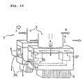
- air is compressed in a compressor 81, fuel is charged to a combustor 82 to generate combustion gas and then the same combustion gas is introduced into a turbine 83 as main stream gas so as to rotate a generator 84.
- a turbine 83 comprises plural rows of static vanes 3 and plural rows of movable vanes 2 which are alternately disposed and an outside peripheral side in the radius direction (or outside diameter side in the radius direction) of the movable vane 2 is so structured to be surrounded by plural ring segments or tip seal segments 90 which are divided in the peripheral direction so as to feed a high temperature gas to the downstream through an appropriate gap between that ring and movable vane 2.
- this ring segment 90 has a cooling structure capable of bearing a high temperature main stream gas 15 discharged from the combustor 82.
- An example of this ring segment 90 having this cooling structure in a conventional gas turbine will be described with reference to FIGs. 8 and 9.
- Cooling medium 89 extracted from the compressor 81 or cooling medium 89 supplied from an appropriate supply source provided outside is supplied to a cavity 96 through an impingement cooling plate 92 in which impingement cooling holes 91 are formed.
- the cooling medium 89 comes into contact with the ring segment 90 so as to cool the ring segment 90 forcibly. After that, it is fed through a cooling path 93 provided in the ring segment 90 so as to cool the ring segment 90 again and then discharged into the main stream gas 15 through a ring segment rear end 94.
- the cooling path 93 may be formed in a circular, rectangular, wave-like or other shape in its cross section and the cooling path 93 is constructed by a plurality of holes extending in the axial direction disposed substantially parallel to one another along the periphery.
- a cavity is provided between the disc portion and gas passage for the disk not to directly contact the high temperature combustion gas and then by supplying air having a higher pressure and lower temperature than in the gas passage to the same cavity, the combustion gas is sealed so as to prevent a rise in the temperature of the rotor.
- the high temperature gas A flows in the direction indicated by an arrow 8 so that it passes the movable vane 1, static vane 3 and movable vane 2 in order from the upstream of the turbine to the downstream thereby forming a gas passage 7.
- the high temperature gas A in the gas passage 7 (corresponds to the main stream gas 15 in FIGs. 1, 16 and others) invades in the upstream cavity 31 and downstream cavity 32 formed by the static vane 3, disc 4 and disc 5, the temperatures of the disc 4 and disc 5 become higher than a tolerable value.
- sealing air B having a higher pressure and lower temperature than in the gas passage 7 is introduced from an outside diameter side of the static vane 3 into a static vane inside cavity 33 (hereinafter referred to as cavity 33) formed by the inside diameter side (or inside peripheral side) of the static vane 3 and a holding ring 38 disposed to oppose it and by supplying the aforementioned sealing air B from the cavity 33 in the direction indicated by an arrow 35 through a hole 34 open to the upstream cavity 31, a pressure of the upstream cavity 31 is kept higher than the pressure of the gas passage 7 so as to prevent an invasion of the high temperature gas A.
- cavity 33 static vane inside cavity 33
- the sealing air B supplied to the upstream cavity 31 in this way passes through a clearance 6 formed by a sealing piece 9 mounted on the holding ring 38 and the discs 4, 5 sealed with a inter-disc seal 50 and flows in a direction indicated by an arrow 36, so that the sealing air B is supplied from the upstream cavity 31 to the downstream cavity 32 having a lower pressure.
- the pressure of the downstream cavity 32 is also kept higher than the pressure of the gas passage 7 corresponding to the downstream position relative to the static vane 3, so that an invasion of the high temperature gas A into the downstream cavity 32 is prevented.
- This sealing air B keeps the pressures of the upstream cavity 31 and downstream cavity 32 higher than the pressure of the gas passage 7 so as to prevent a rise in the temperature of the disc portion and then blows into the gas passage 7. Thus, after this blow, the sealing air B turns to waste air which carries out no work.
- the sealing air B is introduced from an outside diameter side of the static vane 3 into a static vane inside cavity 53 (hereinafter referred to as cavity 53) formed by a box 57 mounted on the inside diameter side of each of the static vane 3, and is supplied through a hole 54 open to the upstream cavity 51 in a direction indicated by an arrow 55 so as to keep the pressure of the upstream cavity 51 higher than the pressure of the gas passage 7, thereby preventing an invasion of the high temperature gas A.
- cavity 53 static vane inside cavity 53
- the box 57 is of a completely sealed structure except the hole 54 for feeding the sealing air B to the upstream cavity 51 so that the sealing air B does not leak from the cavity 53 directly to the downstream cavity 52.
- the amount of the sealing air B supplied from the upstream cavity 51 to the downstream cavity 52 in a direction indicated by an arrow 56 is limited by the clearance 6 formed by the sealing piece 9 mounted on an inside diameter side of the box 57 and the discs 4, 5.
- the box 57 is directly mounted on the inside diameter side of the static vane 3 and because the static vane 3 is disposed in the gas passage 7 so that it is in contact with the high temperature gas A, a temperature change thereof is large and a change rate thereof due to thermal elongation is also large. Therefore, a displacement in the radius direction of the sealing piece 9 mounted on the same box 57 is governed by the box 57 and static vane 3 to become larger.
- the clearance 6 on assembly stage (initial stage) of the turbine needs to be set considering a thermal expansion amount 71 of the static vane 3 as shown in Fig. 14 and therefore, the clearance 6 expands until the thermal expansion reaches its saturation (the amount of the sealing air B needs to be increased), so that the performance of the turbine at the time of partial load drops.
- the thermal expansion amount of the static vane 3 is determined depending on temperature distribution of the combustion gas likely to produce a deviation in temperature distribution, if a maximum of that deviation is considered, it is difficult to reduce the size of the clearance 6.
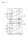
- the holding ring 38 on which the sealing piece 9 is mounted is of a ring-like structure independent of the static vane 3 in the radius direction. Therefore, the displacement of the sealing piece 9 mounted thereon in the radius direction is governed by only the thermal expansion of the holding ring 38.
- the displacement of the clearance 6 in non-steady state is small as indicated as a small displacement 73 and therefore, the clearance 6 at the time of assembly (initial stage) may be set small.
- the displacement of the clearance 6 is independent of the thermal expansion of the static vane 3 which is largely influenced by a temperature distribution of the combustion gas, therefore has a large displacement, it is not influenced by the expansion of the static vane. Therefore, the aforementioned displacement does not have to be considered and accordingly the clearance 6 may be narrowed.
- the flow rate of the sealing air B supplied from the cavity 31 to the cavity 32 can be reduced to a necessary but minimum level all times including a partial load time.
- the cavity 96 In the cooling structure of the ring segment disposed on the outside peripheral side in the radius direction of the movable vane of the above described conventional gas turbine, the cavity 96 needs to be kept under a higher pressure than the main stream gas 15 for the cooling medium 89 to prevent a backlash of the high temperature main stream gas 15. Therefore, the cavity 96 formed on the outside peripheral side of the ring segment is kept under a relatively higher pressure than the main stream gas 15 on the upstream side in the axial direction, when the cooling medium 89 is supplied.
- the cooling medium 89 in the cavity 96 which has been adjusted of pressure in relation to the main stream gas 15 in the upstream side in the axial direction produces an excessive leakage, so that a drop in the turbine efficiency is induced.
- the temperature of the cooling medium 89 in the cooling path 93 is gradually raised by heat exchange for cooling as the medium goes in the downstream in the axial direction, so that it reaches quite high a temperature in the downstream of the ring segment and therefore its cooling performance is reduced.
- the structure of the sealing portion in the industrial gas turbine above mentioned as a conventional example relating to the sealing for the gas turbine disc portion has the following problems in reducing the flow rate of the aforementioned sealing air B.
- the sealing air B introduced from the outside diameter side of the static vane 3 to the cavity 33 is supplied to the upstream cavity 31 through the hole 34 and at the same time leaks directly to the downstream cavity 32 through the gaps 39, 40 as leaking air C.
- the flow rate of the sealing air B supplied is insufficient so that the pressure thereof drops and the high temperature gas A invades.
- a larger amount of the sealing air B taking into account the flow rate of the leaking air C is needed, so that the efficiency of the gas turbine drops.
- the conventional industrial turbine and airplane turbine have advantages and disadvantages, and therefore, it is difficult to determine which is better.
- an object of the present invention is to provide a gas turbine in which the cooling efficiency of its ring segment is improved, a leakage of the sealing air is suppressed and an expansion of the clearance is prevented to ensure a preferable sealing.
- a gas turbine wherein an outside periphery of a ring segment for forming a casing in which a high temperature combustion main stream gas passes is surrounded by an impingement cooling plate so as to form a ring segment cavity therebetween, a static vane inside diameter side cavity is formed by a box provided on an inside periphery of a static vane disposed between a movable vane and an adjacent movable vane thereof operated by the main stream gas in the casing, sealing air introduced into said static vane inside diameter side cavity is fed to another cavity formed in a gap between the movable vane and the static vane so that a pressure therein is kept higher than a pressure in a gas path, said ring segment cavity is divided in the axial direction by a pressure partition plate extending in the circumferential direction between said ring segment and said impingement cooling plate of outside periphery thereof so as to provide plural cavities in which an internal pressure of an upstream cavity is kept higher
- the sealing air introduced to the cavity on the inside diameter side of the static vane is fed to the other cavity formed in a gap between the movable vane and static vane and kept at a higher pressure than the gas path pressure so as to seal the main stream gas.
- the plural cavities divided by the pressure partition plate to the upstream cavity and downstream cavity in the axial direction are adjusted to mutually different pressures, so that they are capable of individually coping appropriately with the main stream gas whose pressure is different between the upstream and downstream in the axial direction.
- backlash of the main stream gas is prevented in the upstream side and leakage of the air through a gap is minimized in the downstream side, so as to improve the efficiency.
- each of said plural cavities is open to a tip end of the movable vane at a position different in the axial direction through a ring segment cooling hole passing through from an outside peripheral side of said ring segment to an inside peripheral side thereof, said ring segment cooling hole extending toward downstream.
- each cavity is open to the tip end of the movable vane through the ring segment cooling hole extending to the downstream and passing through from the outside peripheral side to the inside peripheral side, the ring segment cooling hole being made at a different position in the axial direction.
- the length of the ring segment cooling hole from each cavity to opening thereof to the tip end of the movable vane is reduced so that the cooling medium is blown to the tip end of the movable vane before it is heated.
- the cooling efficiency for the movable vane is improved.
- a gas turbine wherein an outside periphery of a ring segment for forming a casing in which a high temperature combustion main stream gas passes is surrounded by an impingement cooling plate so as to form a ring segment cavity therebetween, a static vane inside diameter side cavity is formed by a box provided on an inside periphery of a static vane disposed between a movable vane and an adjacent movable vane thereof operated by the main stream gas in the casing, sealing air introduced into said static vane inside diameter side cavity is fed to another cavity formed in a gap between the movable vane and the static vane so that a pressure therein is kept higher than a pressure in a gas path, said another cavity includes an upstream cavity of which wall face is formed by a movable vane disc existing in front of the static vane and a downstream cavity of which wall face is formed by another movable vane disc existing in the back of the static vane where a pressure is lower than in said
- a gas turbine wherein an outside periphery of a ring segment for forming a casing in which a high temperature combustion main stream gas passes is surrounded by an impingement cooling plate so as to form a ring segment cavity therebetween, a static vane inside diameter side cavity is formed by a box provided on an inside periphery of a static vane disposed between a movable vane and an adjacent movable vane thereof operated by the main stream gas in the casing, sealing air introduced into said static vane inside diameter side cavity is fed to another cavity formed in a gap between the movable vane and the static vane so that a pressure therein is kept higher than a pressure in a gas path, said ring segment cavity is divided in the axial direction by a pressure partition plate extending in the circumferential direction between said ring segment and said impingement cooling plate of outside periphery thereof so as to provide plural cavities each of which is adjusted to a different pressure thereby constructing a cooling
- a gas turbine according to the third aspect or the fourth aspect further comprising a ring-like holding ring supported movably in the radius direction relative to said box which forms said static vane inside diameter side cavity sealingly from said downstream cavity and having a sealing piece on an inside periphery thereof for regulating a clearance communicating from said upstream cavity to said downstream cavity.
- the cavity inside the static vane supplied with the sealing air is formed by the box sealing it from the downstream cavity, so that the aforementioned sealing air is supplied to the upstream cavity without leakage, thereby inducing no drop in the efficiency.
- the clearance communicating from the upstream cavity to the downstream cavity is regulated by the sealing piece held by the ring-like holding ring movable in the radius direction relative to the aforementioned box, the same clearance is separated from an influence of the thermal deformation of the box and static vane.
- the seal fin enlarges the clearance so that a large amount of the sealing air is allowed to flow, thereby leading to a drop of the efficiency. That is, it is possible to ensure a stabilized supply of the sealing air which does not induce a reduction of the efficiency.
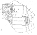
- FIG. 1 shows an entire structure of an embodiment of the present invention.
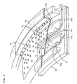
- FIGs. 2-5 show a cooling structure of the outside peripheral side in the radius direction and
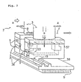
- FIGs. 6, 7 show the sealing structure of the inside diameter side.
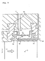
- Reference numeral 90 denotes a ring segment, which is disposed closely to a tip end of a movable vane to seal a gap on the tip end of the movable vane.
- FIGs. 1-3 show one of the plural ring segments divided along the periphery.
- Reference numeral 92 denotes an impingement cooling plate, which is supported by a heat shielding ring 99 so that it is disposed via an appropriate gap relative to the ring segment 90 coaxially therewith along the outside periphery of the ring segment 90.
- the impingement cooling plate 92 has a cavity for receiving cooling medium between it and the aforementioned ring segment 90, the cooling medium being supplied through plural impingement cooling holes 91 provided in the plate face.
- Reference numeral 98 denotes a groove provided on the surface of the ring segment 90, the groove extending along the periphery.
- a pressure partition plate 97 whose top face is in contact with the impingement cooling plate 92 is engaged with the same groove 98 so that the cavity formed between the aforementioned ring segment 90 and the impingement cooling plate 92 is divided to a upstream cavity 96a and a downstream cavity 96b.
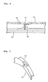
- the pressure partition plate 97 may be so constructed to be divided to a plurality thereof along the circumference like the ring segment 90 and impingement cooling plate 92. In this case, joint portions thereof in the circumferential direction are jointed together at end faces with a minute gap and a minute leakage is permitted. However, by cutting a joint surface of each of the end faces and joining the cut faces together in the sectional direction as shown in FIG. 5, the sealing performance can be improved.
- the inside diameter side of the pressure partition plate 97 is engaged with the groove 98 as described above.
- the outside diameter side opposing it is of inverse L shape as shown in FIG. 4, the shape of the pressure partition plate 97 is not limited to this shape but it is needless to say that a T shape or other shape can be selected.
- An interior of the upstream cavity 96a is open to a range of upstream half portion at the tip end of the movable vane 2 through the cooling path 93a and an interior of the downstream cavity 96b extends substantially parallel with the axial direction and is open to downstream of the movable vane 2 through the cooling path 93b. So, the respective lengths of the cooling paths 93a, 93b are short enough relative to the lengths in the axial direction of the ring segment 90 and the tip end portion of the movable vane 2.
- the rear cooling path 93b may be extended substantially parallel to the front cooling path 93a to open toward the downstream side of the tip end portion of the movable vane 2 so as to directly film-cool the tip end face of the movable vane 2 like the front cooling path 93a.
- each of the impingement cooling plates 92 in the upstream cavity 96a and downstream cavity 96b has a plurality of the impingement cooling holes 91
- the impingement cooling holes 91 opening to the upstream cavity 96a and those 91 opening to the downstream cavity 96b are different in the size, shape and quantity of the opening.
- adjustment of the pressure is made such that the upstream cavity 96a keeps a higher pressure than the downstream cavity 96b and at the same time, the inner pressure of the upstream cavity 96a is higher than the upstream main stream gas 15a and the inner pressure of the downstream cavity 96b is higher than the downstream main stream gas 15b.
- the cooling medium 89 passes through the impingement cooling holes 91 in the impingement cooling plate 92 and impingement-cools the ring segment 90 forming the upstream cavity 96a and downstream cavity 96b. After that, it passes through the plural rows of the ring segment cooling paths 93a and 93b extending in the axial direction so as to cool the ring segment 90 again. Finally, the cooling medium 89 is discharged to the main stream gas 15.
- the ring segment 90 By introducing the cooling medium 89 through the cooling paths 93a, 93b provided to pass through the thickness of the ring segment 90 from the upstream cavity 96a and the downstream cavity 96b, respectively, the ring segment 90 is cooled and further, by blowing out this cooling medium 89 against the tip end of the turbine movable vane 2, it can be expected to cool the turbine movable vanes 2.
- a single partition wall 97 is disposed between the impingement cooling plate 92 and ring segment 90 so as to form the upstream cavity 96a and the downstream cavity 96b, it is needless to say that a plurality of cavities may be formed by a plurality of the partition walls 97.
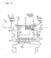
- the structure of the sealing portion comprises the box 57, the holding ring 38 and the sealing piece 9.
- the box 57 is mounted on the inside diameter side of the static vane 3 like the box structure in the conventional airplane gas turbine and forms the cavity 53 completely sealed from outside except the hole 54 for supplying the sealing air B introduced from the outside diameter of the static vane 3 to the upstream cavity 31 on the disc 4.
- the sealing piece 9 is mounted on the same ring-like holding ring 38 as in the conventional industrial gas turbine.
- the clearance 6 formed by the sealing piece 9 and the discs 4, 5 through which the sealing air B supplied from the upstream cavity 31 to the downstream cavity 32 passes is governed by only a difference between the thermal elongation of the same holding ring 38 as in the conventional industrial gas turbine and the thermal elongation plus centrifugal elongation of the discs 4 and 5, so that the clearance is easy to be narrowed.
- the holding ring 38 is coupled with the box 57 via a fitting portion 19, as shown in FIG. 6.
- the fitting portion 19 provides a structure for fitting engagement in the diameter direction and blocks a displacement in the axial direction but allows a displacement in the radius direction freely. Therefore, no blocking on the thermal elongation in the radius direction is performed so that the thermal deformation of the aforementioned static vane 3 and the like does not affect the holding ring 38.
- the cavity 53 formed by the box 57 having the same structure as the box structure of the conventional airplane gas turbine is a completely sealed space except the hole 34 for supplying the sealing air B to the upstream cavity 31 on the disc 4, and generates no air leaking to the other part.
- the flow rate of the sealing air B necessary for maintaining the pressure of the upstream cavity 31 higher than the gas passage 7 can be reduced because the leaking air is not generated in the same cavity 53.
- the sealing piece 9 is mounted on the same ring-like holding ring 38 as in the conventional industrial gas turbine, for setting the clearance 6 for serving as a path for supplying the sealing air B from the upstream cavity 31 to the downstream cavity 32, only the difference between the thermal elongation of the holding ring 38 and the thermal elongation plus the centrifugal elongation of the discs 4, 5 may be considered.
- the clearance 6 on the assembly stage may be set small so that the flow rate of the sealing air B supplied from the upstream cavity 31 to the downstream cavity 32 in full operating state can be reduced.
- the displacement of the clearance 6 is independent of the thermal elongation of the static vane 3 governed by the temperature distribution of the combustion gas having a large deviation, it is not influenced thereby. Therefore, the deviation due to the thermal elongation of the static vane 3 does not have to be considered, and therefore the clearance can be narrowed accordingly, so that the flow rate of the sealing air B from the upstream cavity 31 to the downstream cavity 32 can be reduced.
- the structure of the box 57 which eliminates leaking air in the conventional airplane gas turbine is employed as a sealing structure for preventing an invasion of the combustion gas into the discs 4 and 5 and at the same time, the structure in which the gap 6 in the conventional industrial gas turbine can be narrowed is also employed, thereby obtaining a structure effective for reducing the flow rate of the sealing air B.
- the gas turbine is so constructed that an outside periphery of a ring segment for forming a casing in which a high temperature combustion main stream gas passes is surrounded by an impingement cooling plate so as to form a ring segment cavity therebetween, a static vane inside diameter side cavity is formed by a box provided on an inside periphery of a static vane disposed between a movable vane and an adjacent movable vane thereof operated by the main stream gas in the casing, sealing air introduced into said static vane inside diameter side cavity is fed to another cavity formed in a gap between the movable vane and the static vane so that a pressure therein is kept higher than a pressure in a gas path, said ring segment cavity is divided in the axial direction by a pressure partition plate extending in the circumferential direction between said ring segment and said impingement cooling plate of outside periphery thereof so as to provide plural cavities in which an internal pressure of an upstream cavity is kept higher than an internal pressure of a downstream cavity.
- the sealing air introduced to the cavity on the inside diameter side of the static vane is fed to the other cavity formed in a gap between the movable vane and static vane and kept at a higher pressure than the gas path pressure so as to seal the main stream gas.
- the plural cavities divided by the pressure partition plate to the upstream cavity and downstream cavity in the axial direction are adjusted to mutually different pressures, so that they are capable of individually coping appropriately with the main stream gas whose pressure is different between the upstream and downstream in the axial direction.
- the gas turbine is so constructed that each of said plural cavities is open to a tip end of the movable vane at a position different in the axial direction through a ring segment cooling hole passing through from an outside peripheral side of said ring segment to an inside peripheral side thereof, said ring segment cooling hole extending toward downstream.
- the upstream and downstream cavities are open to the tip end of the movable vane through each of the ring segment cooling holes, the ring segment cooling holes being made at different positions in the axial direction. And the length of the ring segment cooling hole from each cavity to opening thereof to the tip end of the movable vane is reduced so that the cooling medium is blown to the tip end of the movable vane before it is heated. Thereby, the cooling efficiency of the gas turbine can be further improved.
- the gas turbine is so constructed that an outside periphery of a ring segment for forming a casing in which a high temperature combustion main stream gas passes is surrounded by an impingement cooling plate so as to form a ring segment cavity therebetween, a static vane inside diameter side cavity is formed by a box provided on an inside periphery of a static vane disposed between a movable vane and an adjacent movable vane thereof operated by the main stream gas in the casing, sealing air introduced into said static vane inside diameter side cavity is fed to another cavity formed in a gap between the movable vane and the static vane so that a pressure therein is kept higher than a pressure in a gas path, said another cavity includes an upstream cavity of which wall face is formed by a movable vane disc existing in front of the static vane and a downstream cavity of which wall face is formed by another movable vane disc existing in the back of the static vane where a pressure is lower than in said upstream cavity, and the sealing
- the cavity inside of the static vane supplied with the sealing air is formed by the box for sealing it from the downstream cavity and further, the sealing air is supplied to the upstream cavity without leakage. Accordingly, the sealing air is fully supplied without leakage to the upstream cavity and no additional sealing air is needed. Thus, a drop of the efficiency in the turbine is not caused.
- the gas turbine is so constructed that an outside periphery of a ring segment for forming a casing in which a high temperature combustion main stream gas passes is surrounded by an impingement cooling plate so as to form a ring segment cavity therebetween, a static vane inside diameter side cavity is formed by a box provided on an inside periphery of a static vane disposed between a movable vane and an adjacent movable vane thereof operated by the main stream gas in the casing, sealing air introduced into said static vane inside diameter side cavity is fed to another cavity formed in a gap between the movable vane and the static vane so that a pressure therein is kept higher than a pressure in a gas path, said ring segment cavity is divided in the axial direction by a pressure partition plate extending in the circumferential direction between said ring segment and said impingement cooling plate of outside periphery thereof so as to provide plural cavities each of which is adjusted to a different pressure thereby constructing a cooling structure for said ring segment,
- the plural cavities divided by the pressure partition plate to the upstream side and downstream side in the axial direction in which the pressures thereof are adjusted to different pressures to cope with the main stream gas having a different pressure between the upstream and downstream in the axial direction individually and appropriately.
- the backlash of the main stream gas is prevented and on the downstream side, the leakage of the air through a gap is minimized so as to improve the efficiency of the gas turbine.
- the cavity inside the static vane supplied with the sealing air is formed by the box for sealing it from the downstream cavity and the sealing air is supplied to the upstream cavity without leakage. As a result, the sealing air is fully supplied to the upstream cavity without leakage and no additional sealing air is needed. Therefore, a drop of the efficiency of the turbine is not induced.
- the gas turbine is constructed to further comprise a ring-like holding ring supported movably in the radius direction relative to said box which forms said static vane inside diameter side cavity sealingly from said downstream cavity and having a sealing piece on an inside periphery thereof for regulating a clearance communicating from said upstream cavity to said downstream cavity.
- the sealing air is fully supplied to the upstream cavity without leakage, thereby requiring no additional sealing air and inducing no drop in the efficiency.
- the clearance communicating from the upstream cavity to the downstream cavity is regulated by the sealing piece held by the ring-like holding ring movable in the radius direction relative to the box, the same clearance is separated from an influence of the thermal deformation of the box and static vane.
Abstract
Description
Claims (5)
- Gas turbine characterized in that an outside periphery of a ring segment 90 for forming a casing in which a high temperature combustion main stream gas 15 passes is surrounded by an impingement cooling plate 92 so as to form a ring segment cavity 96 therebetween, a static vane inside diameter side cavity 53 is formed by a box 57 provided on an inside periphery of a static vane 3 disposed between a movable vane 2 and an adjacent movable vane 2 thereof operated by the main stream gas 15 in the casing, sealing air introduced into said static vane inside diameter side cavity 53 is fed to another cavity formed in a gap between the movable vane 2 and the static vane 3 so that a pressure therein is kept higher than a pressure in a gas path, said ring segment cavity 96 is divided in the axial direction by a pressure partition plate 97 extending in the circumferential direction between said ring segment 90 and said impingement cooling plate 92 of outside periphery thereof so as to provide plural cavities in which an internal pressure of an upstream cavity 96a is kept higher than an internal pressure of a downstream cavity 96b.
- Gas turbine as claimed in claim 1 characterized in that each of said plural cavities is open to a tip end of the movable vane 2 at a position different in the axial direction through a ring segment cooling hole 98 passing through from an outside peripheral side of said ring segment 90 to an inside peripheral side thereof, said ring segment cooling hole 98 extending toward downstream.
- Gas turbine characterized in that an outside periphery of a ring segment 90 for forming a casing in which a high temperature combustion main stream gas 15 passes is surrounded by an impingement cooling plate 92 so as to form a ring segment cavity 96 therebetween, a static vane inside diameter side cavity 53 is formed by a box 57 provided on an inside periphery of a static vane 3 disposed between a movable vane 2 and an adjacent movable vane 2 thereof operated by the main stream gas 15 in the casing, sealing air introduced into said static vane inside diameter side cavity 53 is fed to another cavity formed in a gap between the movable vane 2 and the static vane 3 so that a pressure therein is kept higher than a pressure in a gas path, said another cavity includes an upstream cavity 31 of which wall face is formed by a movable vane disc 4 existing in front of the static vane 3 and a downstream cavity 32 of which wall face is formed by another movable vane disc 5 existing in the back of the static vane 3 where a pressure is lower than in said upstream cavity 31, and the sealing air is supplied from said static vane inside diameter side cavity 53 to said upstream cavity 31 and said downstream cavity 32 so that the pressures in said upstream cavity 31 and said downstream cavity 32 are raised higher relative to the pressure in the gas path thereby preventing an invasion of the combustion gas 15 into the discs 4, 5.
- Gas turbine characterized in that an outside periphery of a ring segment 90 for forming a casing in which a high temperature combustion main stream gas 15 passes is surrounded by an impingement cooling plate 92 so as to form a ring segment cavity 96 therebetween, a static vane inside diameter side cavity 53 is formed by a box 57 provided on an inside periphery of a static vane 3 disposed between a movable vane 2 and an adjacent movable vane 2 thereof operated by the main stream gas 15 in the casing, sealing air introduced into said static vane inside diameter side cavity 53 is fed to another cavity formed in a gap between the movable vane 2 and the static vane 3 so that a pressure therein is kept higher than a pressure in a gas path, said ring segment cavity 96 is divided in the axial direction by a pressure partition plate 97 extending in the circumferential direction between said ring segment 90 and said impingement cooling plate 92 of outside periphery thereof so as to provide plural cavities each of which is adjusted to a different pressure thereby constructing a cooling structure for said ring segment 90, said another cavity includes an upstream cavity 31 of which wall face is formed by a movable vane disc 4 existing in front of the static vane 3 and a downstream cavity 32 of which wall face is formed by another movable vane disc 5 existing in the back of the static vane 3 where a pressure is lower than in said upstream cavity 31, and the sealing air is supplied from said static vane inside diameter side cavity 53 to said upstream cavity 31 and said downstream cavity 32 so that the pressures in said upstream cavity 31 and said downstream cavity 32 are raised higher relative to the pressure in the gas path thereby preventing an invasion of the combustion gas 15 into the discs 4, 5.
- Gas turbine as claimed in claim 3 or 4 characterized in further comprising a ring-like holding ring 38 supported movably in the radius direction relative to said box 57 which forms said static vane inside diameter side cavity sealingly from said downstream cavity 32 and having a sealing piece 9 on an inside periphery thereof for regulating a clearance 6 communicating from said upstream cavity 31 to said downstream cavity 32.
Priority Applications (1)
| Application Number | Priority Date | Filing Date | Title |
|---|---|---|---|
| EP04023188.8A EP1500789B1 (en) | 1998-03-03 | 1999-03-02 | Impingement cooled ring segment of a gas turbine |
Applications Claiming Priority (4)
| Application Number | Priority Date | Filing Date | Title |
|---|---|---|---|
| JP05044298A JP3631898B2 (en) | 1998-03-03 | 1998-03-03 | Cooling structure of split ring in gas turbine |
| JP5044298 | 1998-03-03 | ||
| JP6671598A JPH11257015A (en) | 1998-03-17 | 1998-03-17 | Sealing structure for disc of gas turbine |
| JP6671598 | 1998-03-17 |
Related Child Applications (1)
| Application Number | Title | Priority Date | Filing Date |
|---|---|---|---|
| EP04023188.8A Division EP1500789B1 (en) | 1998-03-03 | 1999-03-02 | Impingement cooled ring segment of a gas turbine |
Publications (3)
| Publication Number | Publication Date |
|---|---|
| EP0940562A2 true EP0940562A2 (en) | 1999-09-08 |
| EP0940562A3 EP0940562A3 (en) | 2000-08-30 |
| EP0940562B1 EP0940562B1 (en) | 2006-10-18 |
Family
ID=26390912
Family Applications (2)
| Application Number | Title | Priority Date | Filing Date |
|---|---|---|---|
| EP99104200A Expired - Lifetime EP0940562B1 (en) | 1998-03-03 | 1999-03-02 | Gas turbine |
| EP04023188.8A Expired - Lifetime EP1500789B1 (en) | 1998-03-03 | 1999-03-02 | Impingement cooled ring segment of a gas turbine |
Family Applications After (1)
| Application Number | Title | Priority Date | Filing Date |
|---|---|---|---|
| EP04023188.8A Expired - Lifetime EP1500789B1 (en) | 1998-03-03 | 1999-03-02 | Impingement cooled ring segment of a gas turbine |
Country Status (4)
| Country | Link |
|---|---|
| US (1) | US6146091A (en) |
| EP (2) | EP0940562B1 (en) |
| CA (1) | CA2263013C (en) |
| DE (1) | DE69933601T2 (en) |
Cited By (17)
| Publication number | Priority date | Publication date | Assignee | Title |
|---|---|---|---|---|
| EP1106787A2 (en) * | 1999-11-30 | 2001-06-13 | General Electric Company | Turbine nozzle segment band cooling |
| EP1124039A1 (en) * | 2000-02-09 | 2001-08-16 | General Electric Company | Impingement cooling apparatus for a gas turbine shroud system |
| EP1221539A2 (en) * | 2001-01-09 | 2002-07-10 | Mitsubishi Heavy Industries, Ltd. | Sealing for shrouds of a gas turbine |
| EP1329594A1 (en) * | 2002-01-17 | 2003-07-23 | Siemens Aktiengesellschaft | Blade tip clearance control of a gas turbine |
| WO2004057159A1 (en) * | 2002-12-23 | 2004-07-08 | Pratt & Whitney Canada Corp. | Cooling a turbine shroud segment abnd reusing the cooling air |
| EP1582697A1 (en) * | 2004-03-30 | 2005-10-05 | United Technologies Corporation | Cavity on-board injection for leakage flows |
| FR2891862A1 (en) * | 2005-10-12 | 2007-04-13 | Snecma Sa | Perforated plate for cooling cavity of e.g. high pressure turbine, has lateral walls extending from base wall and formed of folded edges that are asymmetric, where one edge presents width greater than that of other edge |
| EP1676981A3 (en) * | 2004-12-29 | 2009-09-16 | United Technologies Corporation | Coolable turbine shroud seal segment |
| EP2299063A1 (en) | 2009-09-17 | 2011-03-23 | Siemens Aktiengesellschaft | Impingement baffle for a gas turbine engine and gas turbine engine |
| CN102686832A (en) * | 2009-12-23 | 2012-09-19 | 涡轮梅坎公司 | Method for cooling turbine stators and cooling system for implementing said method |
| EP2613012A1 (en) * | 2012-01-09 | 2013-07-10 | General Electric Company | Turbine nozzle cooling assembly |
| EP2719869A1 (en) * | 2012-10-12 | 2014-04-16 | MTU Aero Engines GmbH | Axial sealing in a housing structure for a turbomachine |
| EP2796667A1 (en) * | 2013-04-24 | 2014-10-29 | MTU Aero Engines GmbH | Slip ring seal |
| EP2570613A3 (en) * | 2011-09-19 | 2017-03-08 | United Technologies Corporation | Blade Outer Air Seal Assembly Leading Edge Core Configuration |
| EP3159486A1 (en) * | 2015-10-20 | 2017-04-26 | General Electric Company | Wheel space purge flow mixing chamber |
| US10132195B2 (en) | 2015-10-20 | 2018-11-20 | General Electric Company | Wheel space purge flow mixing chamber |
| EP3620611A1 (en) * | 2018-09-05 | 2020-03-11 | United Technologies Corporation | Unified boas support and vane platform |
Families Citing this family (50)
| Publication number | Priority date | Publication date | Assignee | Title |
|---|---|---|---|---|
| US6390769B1 (en) * | 2000-05-08 | 2002-05-21 | General Electric Company | Closed circuit steam cooled turbine shroud and method for steam cooling turbine shroud |
| JP4698847B2 (en) * | 2001-01-19 | 2011-06-08 | 三菱重工業株式会社 | Gas turbine split ring |
| US6530744B2 (en) * | 2001-05-29 | 2003-03-11 | General Electric Company | Integral nozzle and shroud |
| JP3825279B2 (en) | 2001-06-04 | 2006-09-27 | 三菱重工業株式会社 | gas turbine |
| US7063503B2 (en) * | 2004-04-15 | 2006-06-20 | Pratt & Whitney Canada Corp. | Turbine shroud cooling system |
| US20070020088A1 (en) * | 2005-07-20 | 2007-01-25 | Pratt & Whitney Canada Corp. | Turbine shroud segment impingement cooling on vane outer shroud |
| US7520715B2 (en) * | 2005-07-19 | 2009-04-21 | Pratt & Whitney Canada Corp. | Turbine shroud segment transpiration cooling with individual cast inlet and outlet cavities |
| US7621719B2 (en) * | 2005-09-30 | 2009-11-24 | United Technologies Corporation | Multiple cooling schemes for turbine blade outer air seal |
| CA2644099C (en) * | 2006-03-02 | 2013-12-31 | Ihi Corporation | Impingement cooled structure |
| US8668437B1 (en) | 2006-09-22 | 2014-03-11 | Siemens Energy, Inc. | Turbine engine cooling fluid feed system |
| US7665962B1 (en) * | 2007-01-26 | 2010-02-23 | Florida Turbine Technologies, Inc. | Segmented ring for an industrial gas turbine |
| US7837437B2 (en) * | 2007-03-07 | 2010-11-23 | General Electric Company | Turbine nozzle segment and repair method |
| US8439639B2 (en) † | 2008-02-24 | 2013-05-14 | United Technologies Corporation | Filter system for blade outer air seal |
| US8246297B2 (en) | 2008-07-21 | 2012-08-21 | Pratt & Whitney Canada Corp. | Shroud segment cooling configuration |
| CH699232A1 (en) | 2008-07-22 | 2010-01-29 | Alstom Technology Ltd | Gas turbine. |
| EP2239419A1 (en) * | 2009-03-31 | 2010-10-13 | Siemens Aktiengesellschaft | Axial turbo engine rotor with sealing disc |
| US8740551B2 (en) * | 2009-08-18 | 2014-06-03 | Pratt & Whitney Canada Corp. | Blade outer air seal cooling |
| US9528382B2 (en) * | 2009-11-10 | 2016-12-27 | General Electric Company | Airfoil heat shield |
| US9458855B2 (en) * | 2010-12-30 | 2016-10-04 | Rolls-Royce North American Technologies Inc. | Compressor tip clearance control and gas turbine engine |
| US9080458B2 (en) | 2011-08-23 | 2015-07-14 | United Technologies Corporation | Blade outer air seal with multi impingement plate assembly |
| WO2013102171A2 (en) * | 2011-12-31 | 2013-07-04 | Rolls-Royce Corporation | Blade track assembly, components, and methods |
| US9011078B2 (en) * | 2012-01-09 | 2015-04-21 | General Electric Company | Turbine vane seal carrier with slots for cooling and assembly |
| US9033670B2 (en) | 2012-04-11 | 2015-05-19 | Honeywell International Inc. | Axially-split radial turbines and methods for the manufacture thereof |
| US9115586B2 (en) | 2012-04-19 | 2015-08-25 | Honeywell International Inc. | Axially-split radial turbine |
| EP2728255A1 (en) * | 2012-10-31 | 2014-05-07 | Alstom Technology Ltd | Hot gas segment arrangement |
| US9068513B2 (en) * | 2013-01-23 | 2015-06-30 | Siemens Aktiengesellschaft | Seal assembly including grooves in an inner shroud in a gas turbine engine |
| WO2014123965A1 (en) * | 2013-02-07 | 2014-08-14 | United Technologies Corporation | Low leakage multi-directional interface for a gas turbine engine |
| EP2789803A1 (en) | 2013-04-09 | 2014-10-15 | Siemens Aktiengesellschaft | Impingement ring element attachment and sealing |
| US9719362B2 (en) | 2013-04-24 | 2017-08-01 | Honeywell International Inc. | Turbine nozzles and methods of manufacturing the same |
| US9476305B2 (en) | 2013-05-13 | 2016-10-25 | Honeywell International Inc. | Impingement-cooled turbine rotor |
| US8814507B1 (en) | 2013-05-28 | 2014-08-26 | Siemens Energy, Inc. | Cooling system for three hook ring segment |
| WO2015119687A2 (en) * | 2013-11-11 | 2015-08-13 | United Technologies Corporation | Segmented seal for gas turbine engine |
| WO2015138027A2 (en) * | 2013-12-17 | 2015-09-17 | United Technologies Corporation | Meter plate for blade outer air seal |
| US10590785B2 (en) * | 2014-09-09 | 2020-03-17 | United Technologies Corporation | Beveled coverplate |
| US9897318B2 (en) | 2014-10-29 | 2018-02-20 | General Electric Company | Method for diverting flow around an obstruction in an internal cooling circuit |
| US10329934B2 (en) | 2014-12-15 | 2019-06-25 | United Technologies Corporation | Reversible flow blade outer air seal |
| DE102015217078A1 (en) * | 2015-09-07 | 2017-03-09 | MTU Aero Engines AG | Device for limiting a flow channel of a turbomachine |
| US20170198602A1 (en) * | 2016-01-11 | 2017-07-13 | General Electric Company | Gas turbine engine with a cooled nozzle segment |
| JP6775428B2 (en) * | 2017-01-12 | 2020-10-28 | 三菱パワー株式会社 | Split ring surface side member, split ring support side member, split ring, rest side member unit and method |
| EP3351735B1 (en) * | 2017-01-23 | 2023-10-18 | MTU Aero Engines AG | Turbomachine housing element |
| US10612406B2 (en) * | 2018-04-19 | 2020-04-07 | United Technologies Corporation | Seal assembly with shield for gas turbine engines |
| US10989068B2 (en) * | 2018-07-19 | 2021-04-27 | General Electric Company | Turbine shroud including plurality of cooling passages |
| US10907492B2 (en) | 2018-09-07 | 2021-02-02 | Raytheon Technologies Corporation | Blade outer air seal with separate forward and aft pressure chambers |
| US10914192B2 (en) | 2018-09-25 | 2021-02-09 | Raytheon Technologies Corporation | Impingement cooling for gas turbine engine component |
| JP6508499B1 (en) * | 2018-10-18 | 2019-05-08 | 三菱日立パワーシステムズ株式会社 | Gas turbine stator vane, gas turbine provided with the same, and method of manufacturing gas turbine stator vane |
| CN109578091B (en) * | 2018-11-23 | 2021-09-17 | 东方电气集团东方汽轮机有限公司 | Gas turbine cuts apart ring fixed knot and constructs |
| US11105215B2 (en) * | 2019-11-06 | 2021-08-31 | Raytheon Technologies Corporation | Feather seal slot arrangement for a CMC BOAS assembly |
| US11903101B2 (en) | 2019-12-13 | 2024-02-13 | Goodrich Corporation | Internal heating trace assembly |
| CN112412546B (en) * | 2020-11-23 | 2022-01-11 | 东方电气集团东方汽轮机有限公司 | Nozzle chamber of industrial steam turbine without median plane |
| CN112832872B (en) * | 2021-02-03 | 2022-09-06 | 东方电气集团东方汽轮机有限公司 | Drainage rotary gland seal for steam turbine |
Family Cites Families (18)
| Publication number | Priority date | Publication date | Assignee | Title |
|---|---|---|---|---|
| US3728039A (en) * | 1966-11-02 | 1973-04-17 | Gen Electric | Fluid cooled porous stator structure |
| FR1548541A (en) * | 1967-10-24 | 1968-12-06 | ||
| CH489699A (en) * | 1968-03-22 | 1970-04-30 | Sulzer Ag | Guide vane ring for turbo machines |
| US3807891A (en) * | 1972-09-15 | 1974-04-30 | United Aircraft Corp | Thermal response turbine shroud |
| WO1982003657A1 (en) * | 1981-04-10 | 1982-10-28 | Davis Warren W | A floating expansion control ring |
| US4526226A (en) * | 1981-08-31 | 1985-07-02 | General Electric Company | Multiple-impingement cooled structure |
| GB2125111B (en) * | 1982-03-23 | 1985-06-05 | Rolls Royce | Shroud assembly for a gas turbine engine |
| JPS59134302A (en) * | 1983-01-24 | 1984-08-02 | Toshiba Corp | Corrosion preventive device for steam turbine |
| US5048288A (en) * | 1988-12-20 | 1991-09-17 | United Technologies Corporation | Combined turbine stator cooling and turbine tip clearance control |
| US4930980A (en) * | 1989-02-15 | 1990-06-05 | Westinghouse Electric Corp. | Cooled turbine vane |
| JPH0552102A (en) * | 1991-08-23 | 1993-03-02 | Toshiba Corp | Gas turbine |
| US5217348A (en) * | 1992-09-24 | 1993-06-08 | United Technologies Corporation | Turbine vane assembly with integrally cast cooling fluid nozzle |
| WO1994012775A1 (en) * | 1992-11-24 | 1994-06-09 | United Technologies Corporation | Coolable outer air seal assembly for a turbine |
| US5480281A (en) * | 1994-06-30 | 1996-01-02 | General Electric Co. | Impingement cooling apparatus for turbine shrouds having ducts of increasing cross-sectional area in the direction of post-impingement cooling flow |
| US5488825A (en) * | 1994-10-31 | 1996-02-06 | Westinghouse Electric Corporation | Gas turbine vane with enhanced cooling |
| EP0791127B1 (en) * | 1994-11-10 | 2000-03-08 | Siemens Westinghouse Power Corporation | Gas turbine vane with a cooled inner shroud |
| JPH0932580A (en) * | 1995-07-12 | 1997-02-04 | Mitsubishi Heavy Ind Ltd | Gas turbine blade tip clearance control device |
| JP3416447B2 (en) * | 1997-03-11 | 2003-06-16 | 三菱重工業株式会社 | Gas turbine blade cooling air supply system |
-
1999
- 1999-02-24 US US09/256,102 patent/US6146091A/en not_active Expired - Lifetime
- 1999-02-25 CA CA002263013A patent/CA2263013C/en not_active Expired - Fee Related
- 1999-03-02 EP EP99104200A patent/EP0940562B1/en not_active Expired - Lifetime
- 1999-03-02 EP EP04023188.8A patent/EP1500789B1/en not_active Expired - Lifetime
- 1999-03-02 DE DE69933601T patent/DE69933601T2/en not_active Expired - Lifetime
Non-Patent Citations (1)
| Title |
|---|
| None |
Cited By (25)
| Publication number | Priority date | Publication date | Assignee | Title |
|---|---|---|---|---|
| EP1106787A2 (en) * | 1999-11-30 | 2001-06-13 | General Electric Company | Turbine nozzle segment band cooling |
| EP1106787A3 (en) * | 1999-11-30 | 2004-03-17 | General Electric Company | Turbine nozzle segment band cooling |
| EP1124039A1 (en) * | 2000-02-09 | 2001-08-16 | General Electric Company | Impingement cooling apparatus for a gas turbine shroud system |
| EP1221539A3 (en) * | 2001-01-09 | 2004-09-01 | Mitsubishi Heavy Industries, Ltd. | Sealing for shrouds of a gas turbine |
| EP1221539A2 (en) * | 2001-01-09 | 2002-07-10 | Mitsubishi Heavy Industries, Ltd. | Sealing for shrouds of a gas turbine |
| EP1329594A1 (en) * | 2002-01-17 | 2003-07-23 | Siemens Aktiengesellschaft | Blade tip clearance control of a gas turbine |
| WO2004057159A1 (en) * | 2002-12-23 | 2004-07-08 | Pratt & Whitney Canada Corp. | Cooling a turbine shroud segment abnd reusing the cooling air |
| US6899518B2 (en) | 2002-12-23 | 2005-05-31 | Pratt & Whitney Canada Corp. | Turbine shroud segment apparatus for reusing cooling air |
| EP1582697A1 (en) * | 2004-03-30 | 2005-10-05 | United Technologies Corporation | Cavity on-board injection for leakage flows |
| EP1676981A3 (en) * | 2004-12-29 | 2009-09-16 | United Technologies Corporation | Coolable turbine shroud seal segment |
| FR2891862A1 (en) * | 2005-10-12 | 2007-04-13 | Snecma Sa | Perforated plate for cooling cavity of e.g. high pressure turbine, has lateral walls extending from base wall and formed of folded edges that are asymmetric, where one edge presents width greater than that of other edge |
| EP2299063A1 (en) | 2009-09-17 | 2011-03-23 | Siemens Aktiengesellschaft | Impingement baffle for a gas turbine engine and gas turbine engine |
| US9988922B2 (en) | 2009-09-17 | 2018-06-05 | Siemens Aktiengesellschaft | Impingement baffle for a gas turbine engine and gas turbine engine |
| CN102686832A (en) * | 2009-12-23 | 2012-09-19 | 涡轮梅坎公司 | Method for cooling turbine stators and cooling system for implementing said method |
| EP2570613A3 (en) * | 2011-09-19 | 2017-03-08 | United Technologies Corporation | Blade Outer Air Seal Assembly Leading Edge Core Configuration |
| US8944751B2 (en) | 2012-01-09 | 2015-02-03 | General Electric Company | Turbine nozzle cooling assembly |
| EP2613012A1 (en) * | 2012-01-09 | 2013-07-10 | General Electric Company | Turbine nozzle cooling assembly |
| EP2719869A1 (en) * | 2012-10-12 | 2014-04-16 | MTU Aero Engines GmbH | Axial sealing in a housing structure for a turbomachine |
| US9605551B2 (en) | 2012-10-12 | 2017-03-28 | MTU Aero Engines AG | Axial seal in a casing structure for a fluid flow machine |
| EP2796667A1 (en) * | 2013-04-24 | 2014-10-29 | MTU Aero Engines GmbH | Slip ring seal |
| US9835039B2 (en) | 2013-04-24 | 2017-12-05 | MTU Aero Engines AG | Slide ring seal |
| EP3159486A1 (en) * | 2015-10-20 | 2017-04-26 | General Electric Company | Wheel space purge flow mixing chamber |
| US10125632B2 (en) | 2015-10-20 | 2018-11-13 | General Electric Company | Wheel space purge flow mixing chamber |
| US10132195B2 (en) | 2015-10-20 | 2018-11-20 | General Electric Company | Wheel space purge flow mixing chamber |
| EP3620611A1 (en) * | 2018-09-05 | 2020-03-11 | United Technologies Corporation | Unified boas support and vane platform |
Also Published As
| Publication number | Publication date |
|---|---|
| CA2263013C (en) | 2002-05-14 |
| EP1500789B1 (en) | 2013-06-05 |
| DE69933601T2 (en) | 2007-08-23 |
| CA2263013A1 (en) | 1999-09-03 |
| EP0940562B1 (en) | 2006-10-18 |
| US6146091A (en) | 2000-11-14 |
| EP0940562A3 (en) | 2000-08-30 |
| EP1500789A1 (en) | 2005-01-26 |
| DE69933601D1 (en) | 2006-11-30 |
Similar Documents
| Publication | Publication Date | Title |
|---|---|---|
| CA2263013C (en) | Gas turbine | |
| US7621719B2 (en) | Multiple cooling schemes for turbine blade outer air seal | |
| US6860108B2 (en) | Gas turbine tail tube seal and gas turbine using the same | |
| JP2001107704A (en) | Coolable air foil, cooling circuit and cooling method for wall | |
| US8206093B2 (en) | Gas turbine with a gap blocking device | |
| JP2006189044A (en) | Blade outer air seal assembly and turbine blade shroud assembly | |
| EP2419609B1 (en) | Cooled one piece casing of a turbo machine | |
| JP2001317302A (en) | Film cooling for closed loop cooled airfoil | |
| JP2005337236A (en) | Gas turbine engine and its operating method | |
| US20100098554A1 (en) | Blade for a rotor | |
| JP4170583B2 (en) | Cooling air distribution device in the turbine stage of a gas turbine | |
| JP2006307853A (en) | Method for adjusting radial gap in axial flow fluid machine and compressor | |
| JPS634001B2 (en) | ||
| JP2010014119A (en) | Combustor transition piece rear end cooling and associated method | |
| CN107916996B (en) | Stator heat shield segments for gas turbine power plants | |
| JPH0681675A (en) | Gas turbine and stage device therefor | |
| US6536201B2 (en) | Combustor turbine successive dual cooling | |
| US8393161B2 (en) | Combustion chamber and gas turbine installation | |
| JPH0552102A (en) | Gas turbine | |
| JP2004251280A (en) | Turbine vane cooled by reduction of leakage of cooling air | |
| JP3631898B2 (en) | Cooling structure of split ring in gas turbine | |
| US4460313A (en) | Heat shield for radial gas turbine | |
| JP2008309051A (en) | Cooling structure for turbine shroud | |
| JP3930274B2 (en) | Gas turbine combustor | |
| JPS62153504A (en) | Shrouding segment |
Legal Events
| Date | Code | Title | Description |
|---|---|---|---|
| PUAI | Public reference made under article 153(3) epc to a published international application that has entered the european phase |
Free format text: ORIGINAL CODE: 0009012 |
|
| 17P | Request for examination filed |
Effective date: 19990330 |
|
| AK | Designated contracting states |
Kind code of ref document: A2 Designated state(s): CH DE FR GB IT LI |
|
| AX | Request for extension of the european patent |
Free format text: AL;LT;LV;MK;RO;SI |
|
| PUAL | Search report despatched |
Free format text: ORIGINAL CODE: 0009013 |
|
| AK | Designated contracting states |
Kind code of ref document: A3 Designated state(s): AT BE CH CY DE DK ES FI FR GB GR IE IT LI LU MC NL PT SE |
|
| AX | Request for extension of the european patent |
Free format text: AL;LT;LV;MK;RO;SI |
|
| RIC1 | Information provided on ipc code assigned before grant |
Free format text: 7F 01D 11/10 A, 7F 01D 11/24 B, 7F 02C 7/18 B, 7F 01D 11/00 B, 7F 01D 25/12 B |
|
| AKX | Designation fees paid |
Free format text: CH DE FR GB IT LI |
|
| 17Q | First examination report despatched |
Effective date: 20040407 |
|
| GRAP | Despatch of communication of intention to grant a patent |
Free format text: ORIGINAL CODE: EPIDOSNIGR1 |
|
| GRAS | Grant fee paid |
Free format text: ORIGINAL CODE: EPIDOSNIGR3 |
|
| GRAA | (expected) grant |
Free format text: ORIGINAL CODE: 0009210 |
|
| AK | Designated contracting states |
Kind code of ref document: B1 Designated state(s): CH DE FR GB IT LI |
|
| PG25 | Lapsed in a contracting state [announced via postgrant information from national office to epo] |
Ref country code: LI Free format text: LAPSE BECAUSE OF FAILURE TO SUBMIT A TRANSLATION OF THE DESCRIPTION OR TO PAY THE FEE WITHIN THE PRESCRIBED TIME-LIMIT Effective date: 20061018 Ref country code: IT Free format text: LAPSE BECAUSE OF FAILURE TO SUBMIT A TRANSLATION OF THE DESCRIPTION OR TO PAY THE FEE WITHIN THE PRESCRIBED TIME-LIMIT;WARNING: LAPSES OF ITALIAN PATENTS WITH EFFECTIVE DATE BEFORE 2007 MAY HAVE OCCURRED AT ANY TIME BEFORE 2007. THE CORRECT EFFECTIVE DATE MAY BE DIFFERENT FROM THE ONE RECORDED. Effective date: 20061018 Ref country code: CH Free format text: LAPSE BECAUSE OF FAILURE TO SUBMIT A TRANSLATION OF THE DESCRIPTION OR TO PAY THE FEE WITHIN THE PRESCRIBED TIME-LIMIT Effective date: 20061018 |
|
| REG | Reference to a national code |
Ref country code: GB Ref legal event code: FG4D |
|
| REG | Reference to a national code |
Ref country code: CH Ref legal event code: EP |
|
| REF | Corresponds to: |
Ref document number: 69933601 Country of ref document: DE Date of ref document: 20061130 Kind code of ref document: P |
|
| REG | Reference to a national code |
Ref country code: CH Ref legal event code: PL |
|
| EN | Fr: translation not filed | ||
| PLBE | No opposition filed within time limit |
Free format text: ORIGINAL CODE: 0009261 |
|
| STAA | Information on the status of an ep patent application or granted ep patent |
Free format text: STATUS: NO OPPOSITION FILED WITHIN TIME LIMIT |
|
| 26N | No opposition filed |
Effective date: 20070719 |
|
| GBPC | Gb: european patent ceased through non-payment of renewal fee |
Effective date: 20070302 |
|
| PG25 | Lapsed in a contracting state [announced via postgrant information from national office to epo] |
Ref country code: GB Free format text: LAPSE BECAUSE OF NON-PAYMENT OF DUE FEES Effective date: 20070302 Ref country code: FR Free format text: LAPSE BECAUSE OF FAILURE TO SUBMIT A TRANSLATION OF THE DESCRIPTION OR TO PAY THE FEE WITHIN THE PRESCRIBED TIME-LIMIT Effective date: 20070601 |
|
| PG25 | Lapsed in a contracting state [announced via postgrant information from national office to epo] |
Ref country code: FR Free format text: LAPSE BECAUSE OF FAILURE TO SUBMIT A TRANSLATION OF THE DESCRIPTION OR TO PAY THE FEE WITHIN THE PRESCRIBED TIME-LIMIT Effective date: 20061018 |
|
| PGFP | Annual fee paid to national office [announced via postgrant information from national office to epo] |
Ref country code: DE Payment date: 20180220 Year of fee payment: 20 |
|
| REG | Reference to a national code |
Ref country code: DE Ref legal event code: R071 Ref document number: 69933601 Country of ref document: DE |