EP1582277A1 - Device for smoothing gears - Google Patents
Device for smoothing gears Download PDFInfo
- Publication number
- EP1582277A1 EP1582277A1 EP04003106A EP04003106A EP1582277A1 EP 1582277 A1 EP1582277 A1 EP 1582277A1 EP 04003106 A EP04003106 A EP 04003106A EP 04003106 A EP04003106 A EP 04003106A EP 1582277 A1 EP1582277 A1 EP 1582277A1
- Authority
- EP
- European Patent Office
- Prior art keywords
- carriage
- smoothing
- smoothed
- gear
- wheel
- Prior art date
- Legal status (The legal status is an assumption and is not a legal conclusion. Google has not performed a legal analysis and makes no representation as to the accuracy of the status listed.)
- Granted
Links
Images

Classifications
-
- B—PERFORMING OPERATIONS; TRANSPORTING
- B21—MECHANICAL METAL-WORKING WITHOUT ESSENTIALLY REMOVING MATERIAL; PUNCHING METAL
- B21H—MAKING PARTICULAR METAL OBJECTS BY ROLLING, e.g. SCREWS, WHEELS, RINGS, BARRELS, BALLS
- B21H5/00—Making gear wheels, racks, spline shafts or worms
- B21H5/02—Making gear wheels, racks, spline shafts or worms with cylindrical outline, e.g. by means of die rolls
- B21H5/022—Finishing gear teeth with cylindrical outline, e.g. burnishing
Definitions
- the invention relates to a device for smoothing of gears according to the preamble of the main claim.
- the object of the invention is a device for smoothing gears to make available that is simple and inexpensive and easy on different diameters of gears to be smoothed adjustable and to be maintained.
- This design allows a complete separation of the clamping a gear to be smoothed from the function of its coaxial Alignment to the longitudinal direction of the oscillation axis of the clamping device and also of the technical design of the clamping device itself and is simple and manageable and thereby very economical to produce and easy to maintain.
- the first carriage is designed as a frame and on Guide rails stored on a machine table and the second Carriage disposed within the frame of the first carriage and stored on the same guide rails, wherein the pressure cylinder is arranged on the frame of the first carriage and over a Push rod moves the second slide within the frame, allowing the arranged on the second carriage pair of smoothing in Direction to the single, set on the first slide level below Move clamping of the gear to be smoothed solve.
- a positioning cylinder is articulated, whose free End either on the first slide or on the second slide can, so that the entire clamping unit in the clamped state a gear to be smoothed along the guide rails so positioned can be that the rotation axis of a gear to be smoothed runs coaxially with a central axis of its clamping device.
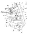
- the device for smoothing gears It consists of a machine table 10, mounted on the two parallel guide rails 11 are on which a frame-shaped carriage 12 for a by a motor 22 driven smoothing wheel 5 is slidably disposed, and within of the carriage 12, another carriage 13 for a driven Pair of smoothing wheels 5, wherein on the carriage 12 for the driven Smoothing 5 a pressing cylinder 14 is arranged, the slide 13th for the driven pair of smoothing wheels 5 in the direction of the driven Smoothing presses 5, wherein between the pair of polishing wheels 5 and the individual smoothing wheel 5 a smoothing gear 1 as a workpiece during operation is kept clamped under a high radial pressure.
- axial the gear 1 to be smoothed by a clamping device 16 is radial movably clamped, which is arranged on a C-shaped bracket 17, which in turn via spring assemblies 18 and an eccentric 19 at a holding frame 21 is fixed so that it has an eccentric drive 20 a vertical oscillation of the axially clamped only, radially quasi floating gear 1 allows.
- a contact pressure of about 150 to 500 kg for floating clamping of the gear to be smoothed 1 can be applied.
Abstract
Description
Die Erfindung betrifft eine Vorrichtung zum Glätten von Zahnrädern gemäß dem Oberbegriff des Hauptanspruchs.The invention relates to a device for smoothing of gears according to the preamble of the main claim.
Es ist eine Zahnradpolier- und -honmaschine bekannt, DE 3230860 C2, die drei zahnradartige Bearbeitungselemente für ein zu bearbeitendes Zahnrad aufweist, welches während einer seitlichen Hin- und Herbewegung einer Werkstückaufnahmeeinrichtung umlaufend angetrieben ist. Die Arbeitsweise der neuerungsgemäßen Vorrichtung zum Glätten von Zahnrädern arbeitet sehr ähnlich, wobei jedoch keine spanabhebende Bearbeitung erfolgt sondern im Wesentlichen ein Reinigen der Zahnflanken, etwa von noch aus dem Herstellungsprozess anhaftenden Verunreinigungen. Die bekannte Vorrichtung ist kompliziert aufgebaut und pflegeintensiv und muss mit einem Kühl- und Schmiermittel betrieben werden. Des Weiteren gestaltet sich eine Anpassung der Konstruktion an unterschiedlich große Werkstücke, insbesondere die Nachführung der Oszillationsachse sehr aufwändig.There is known a gear polishing and honing machine, DE 3230860 C2, the three gear-like machining elements for a machined Gear having, during a lateral reciprocation a workpiece receiving device is driven circumferentially. The operation of the inventive device for smoothing Gears works very similar, but no cutting Machining takes place but essentially a cleaning of the tooth flanks, for example of impurities still adhering to the production process. The known device is complicated and care-intensive and must be operated with a coolant and lubricant. Furthermore, an adaptation of the construction is different Large workpieces, in particular the tracking of the oscillation axis very expensive.
Aufgabe der Erfindung ist es, eine Vorrichtung zum Glätten von Zahnrädern zur Verfügung zu stellen, die einfach und kostengünstig aufgebaut und leicht auf unterschiedliche Durchmesser von zu glättenden Zahnrädern einstellbar und zu warten ist. The object of the invention is a device for smoothing gears to make available that is simple and inexpensive and easy on different diameters of gears to be smoothed adjustable and to be maintained.
Die Lösung dieser Aufgabe erfolgt in Verbindung mit den Oberbegriffsmerkmalen erfindungsgemäß dadurch, dass das einzelne Glättrad und die weiteren Glätträder auf Lagerböcken gelagert sind, die so gegeneinander verspannbar sind, dass ein dazwischen angeordnetes zu glättendes Zahnrad automatisch zentriert und mit einer vorherbestimmbaren Kraft beaufschlagbar ist, wodurch eine Einspanneinheit der Vorrichtung erzeugt ist, die die zu glättenden Zahnräder quasi schwimmend eingespannt hält, da die gesamte Einspanneinheit parallel verschieblich ausgebildet ist, sodass die Drehachse des zu glättenden Zahnrades einfach koaxial zur Mittelachse einer oszillierenden Klemmvorrichtung des zu glättenden Zahnrades einrichtbar ist, wobei die Klemmvorrichtung und deren Oszillationsantrieb ortsfest am Maschinentisch angeordnet sind.The solution to this problem is in conjunction with the generic features according to the invention in that the individual smoothing wheel and the other smoothing wheels are mounted on bearing blocks, the so against each other are braced that an interposed to be smoothed Gear automatically centered and with a predictable Force can be acted upon, whereby a clamping unit of the device is generated, which clamped the wheels to be smoothed almost floating holds, since the entire clamping unit formed parallel displaceable is, so that the axis of rotation of the gear to be smoothed easy coaxial to the central axis of an oscillating clamping device of smoothing gear can be set, wherein the clamping device and whose oscillation drive are arranged stationarily on the machine table.
Diese Konstruktion ermöglicht eine vollständige Trennung der Einspannung eines zu glättenden Zahnrades von der Funktion seiner koaxialen Ausrichtung zur Längsrichtung der Oszillationsachse der Klemmvorrichtung und auch von der technischen Ausführung der Klemmvorrichtung selber und ist dabei einfach und überschaubar ausgeführt und dadurch sehr wirtschaftlich herstellbar und einfach zu warten.This design allows a complete separation of the clamping a gear to be smoothed from the function of its coaxial Alignment to the longitudinal direction of the oscillation axis of the clamping device and also of the technical design of the clamping device itself and is simple and manageable and thereby very economical to produce and easy to maintain.
Weitere vorteilhafte Ausgestaltungen des Gegenstandes der Erfindung ergeben sich mit und in Kombination aus den nachfolgenden Unteransprüchen.Further advantageous embodiments of the subject invention arise with and in combination from the following subclaims.
Dadurch, dass der Lagerbock für das einzelne Glättrad auf einem ersten Schlitten und die Lagerböcke für die beiden weiteren Glätträder auf einem zweiten Schlitten angeordnet sind und beide Schlitten über eine Schubstange von dem Anpresszylinder gegeneinander verspannbar sind, wird eine Konstruktion erreicht, die nach außen vollkommen kräftefrei ist, sodass diese gesamte Einspanneinheit über einen sehr kleinen elektromechanischen, hydraulischen oder pneumatischen Antrieb, wie einen Positionierzylinder verschoben werden kann. Der Anpresszylinder kann ebenfalls wahlfrei elektromotorisch, hydraulisch und/ oder pneumatisch arbeitend ausgebildet sein.Due to the fact that the bearing block for the single smoothing wheel on a first Sled and the bearing blocks for the other two smoothing wheels on one second carriages are arranged and both carriages have one Push rod of the pressure cylinder are braced against each other, a construction is achieved that is completely free of forces to the outside so that this entire clamping unit has a very small electromechanical, hydraulic or pneumatic drive, like one Positioning cylinder can be moved. The pressure cylinder can also optional electric motor, hydraulic and / or pneumatic be trained working.
Gemäß einer besonders bevorzugten Ausführungsform des Gegenstandes der Erfindung ist der erste Schlitten als Rahmen ausgebildet und auf Führungsschienen auf einem Maschinentisch gelagert und der zweite Schlitten innerhalb des Rahmens des ersten Schlittens angeordnet und auf den selben Führungsschienen gelagert, wobei der Anpresszylinder am Rahmen des ersten Schlittens angeordnet ist und über eine Schubstange den zweiten Schlitten innerhalb des Rahmens bewegt, sodass sich das auf dem zweiten Schlitten angeordnete Glättradpaar in Richtung auf das einzelne, am ersten Schlitten festgelegte Glättrad unter Einspannung des zu glättenden Zahnrades bewegen lösst.According to a particularly preferred embodiment of the article the invention, the first carriage is designed as a frame and on Guide rails stored on a machine table and the second Carriage disposed within the frame of the first carriage and stored on the same guide rails, wherein the pressure cylinder is arranged on the frame of the first carriage and over a Push rod moves the second slide within the frame, allowing the arranged on the second carriage pair of smoothing in Direction to the single, set on the first slide level below Move clamping of the gear to be smoothed solve.
Die gemeinsame Nutzung der Führungsschienen sowie der konstruktive Aufbau der Schlitten sind demnach sehr einfach ausgeführt und aufgrund der Übersichtlichkeit auch sehr wartungsfreundlich. Am Maschinentisch ist des Weiteren ein Positionierzylinder angelenkt, dessen freies Ende entweder am ersten Schlitten oder am zweiten Schlitten angreifen kann, sodass die gesamte Einspanneinheit im eingespannten Zustand eines zu glättenden Zahnrades entlang der Führungsschienen so positioniert werden kann, dass die Drehachse eines zu glättenden Zahnrades koaxial mit einer Mittelachse seiner Klemmvorrichtung verläuft. The common use of the guide rails as well as the constructive Structure of the carriage are therefore very simple and due the clarity also very easy to maintain. At the machine table Furthermore, a positioning cylinder is articulated, whose free End either on the first slide or on the second slide can, so that the entire clamping unit in the clamped state a gear to be smoothed along the guide rails so positioned can be that the rotation axis of a gear to be smoothed runs coaxially with a central axis of its clamping device.
Nachfolgend ist ein Ausführungsbeispiel der Erfindung anhand von Zeichnungen näher beschrieben. Es zeigen:
- Fig. 1
- eine Gesamtansicht der Vorrichtung zum Glätten von Zahnrädern, und
- Fig. 2
- eine vergrößerte Teilansicht der Einspanneinheit.
- Fig. 1
- an overall view of the device for smoothing gears, and
- Fig. 2
- an enlarged partial view of the clamping unit.
Die Vorrichtung zum Glätten von Zahnrädern Sie besteht aus einem Maschinentisch
10, auf dem zwei parallele Führungsschienen 11 aufgesetzt
sind, auf denen ein rahmenförmiger Schlitten 12 für ein durch einen Motor
22 angetriebenes Glättrad 5 verschieblich angeordnet ist, sowie innerhalb
des Schlittens 12 ein weiterer Schlitten 13 für ein getriebenes
Paar von Glätträdern 5, wobei am Schlitten 12 für das angetriebene
Glättrad 5 ein Anpresszylinder 14 angeordnet ist, der den Schlitten 13
für das getriebene Paar Glätträder 5 in Richtung auf das angetriebene
Glättrad 5 anpresst, wobei zwischen dem Paar Glätträder 5 und dem
einzelnen Glättrad 5 ein zu glättendes Zahnrad 1 als Werkstück im Betrieb
unter einem hohen radialen Druck eingespannt gehalten wird. Axial
wird das zu glättende Zahnrad 1 von einer Klemmvorrichtung 16 radial
beweglich geklemmt, die an einem C-förmigen Bügel 17 angeordnet ist,
welcher seinerseits über Federpakete 18 und über einen Exzenter 19 an
einem Haltegestell 21 so befestigt ist, dass er über einen Exzenterantrieb
20 eine vertikale Oszillation des axial nur geklemmten, radial quasi
schwimmend gelagerten Zahnrades 1 ermöglicht.The device for smoothing gears It consists of a machine table
10, mounted on the two
Um die Vorrichtung auf unterschiedlich große zu glättende Zahnräder 1
und/ oder unterschiedliche Glätträder 5 einstellen zu können, ist der gesamte
Schlitten 13 zusammen mit dem Schlitten 12 über einen kleinen
Positionierzylinder 15 im Verhältnis zu einer festen vertikalen Achse der
Klemmvorrichtung 16 auf den Führungsschienen 11 verfahrbar.
Wie insbesondere aus Fig. 2 deutlich wird, ist der zweite Schlitten 13 etwa
U-förmig ausgebildet, wobei die Lagerböcke 27 für das Paar Glatträder
5 auf dem Verbindungsschenkel angeordnet sind und unterhalb
der beiden Seitenschenkel die Führungen 30 zur Lagerung des Schlittens
13 auf den Führungsschienen 11 angeordnet sind. Über den Anpresszylinder
14 kann eine Anpresskraft von etwa 150 bis 500kg zur schwimmenden
Einspannung des zu glättenden Zahnrades 1 aufgebracht werden.In order to adjust the device to different sized to be smoothed
2, the
Claims (7)
Priority Applications (7)
| Application Number | Priority Date | Filing Date | Title |
|---|---|---|---|
| PL04003106T PL1582277T3 (en) | 2004-03-01 | 2004-03-01 | Device for smoothing gears |
| AT04003106T ATE385865T1 (en) | 2004-03-01 | 2004-03-01 | DEVICE FOR SMOOTHING GEARS |
| EP04003106A EP1582277B1 (en) | 2004-03-01 | 2004-03-01 | Device for smoothing gears |
| DE502004006188T DE502004006188D1 (en) | 2004-03-01 | 2004-03-01 | Device for smoothing gears |
| ES04003106T ES2301890T3 (en) | 2004-03-01 | 2004-03-01 | DEVICE WHEELED TOOLS DEVICE. |
| CA002465452A CA2465452C (en) | 2004-02-12 | 2004-04-27 | Device for smoothing gear wheels |
| US10/846,213 US7004826B2 (en) | 2004-03-01 | 2004-05-10 | Device for smoothing gear wheels |
Applications Claiming Priority (1)
| Application Number | Priority Date | Filing Date | Title |
|---|---|---|---|
| EP04003106A EP1582277B1 (en) | 2004-03-01 | 2004-03-01 | Device for smoothing gears |
Publications (2)
| Publication Number | Publication Date |
|---|---|
| EP1582277A1 true EP1582277A1 (en) | 2005-10-05 |
| EP1582277B1 EP1582277B1 (en) | 2008-02-13 |
Family
ID=34833581
Family Applications (1)
| Application Number | Title | Priority Date | Filing Date |
|---|---|---|---|
| EP04003106A Expired - Lifetime EP1582277B1 (en) | 2004-02-12 | 2004-03-01 | Device for smoothing gears |
Country Status (7)
| Country | Link |
|---|---|
| US (1) | US7004826B2 (en) |
| EP (1) | EP1582277B1 (en) |
| AT (1) | ATE385865T1 (en) |
| CA (1) | CA2465452C (en) |
| DE (1) | DE502004006188D1 (en) |
| ES (1) | ES2301890T3 (en) |
| PL (1) | PL1582277T3 (en) |
Cited By (2)
| Publication number | Priority date | Publication date | Assignee | Title |
|---|---|---|---|---|
| EP2022576A1 (en) * | 2007-08-03 | 2009-02-11 | Wolfgang Linnenbrink | Method of improving the running performance of gearwheels and gear finishing machine for implementing the method |
| DE102017126988A1 (en) | 2017-11-16 | 2019-05-16 | Profiroll Technologies Gmbh | Tool, machine and method for the smooth rolling of toothed workpieces |
Families Citing this family (7)
| Publication number | Priority date | Publication date | Assignee | Title |
|---|---|---|---|---|
| US7169023B2 (en) * | 2004-06-08 | 2007-01-30 | Asmo Co., Ltd. | Method and apparatus for manufacturing hourglass worm rolling die |
| CN108098075B (en) * | 2016-11-24 | 2019-07-19 | 丹阳市华清机车配件有限公司 | A kind of door closer rack gear plunger mill teeth device and its working method |
| CN108772781A (en) * | 2018-06-13 | 2018-11-09 | 何磊 | A kind of small-size shaft bearing sleeve inner wall polishing positioning device |
| CN109277919B (en) * | 2018-11-14 | 2024-03-22 | 漳浦金盛智能科技有限公司 | Polisher |
| CN112318254A (en) * | 2020-10-27 | 2021-02-05 | 韦熙斌 | Sprocket burring device is used in metal material processing |
| CN113618564A (en) * | 2021-07-09 | 2021-11-09 | 林元霞 | Raw bamboo joint polishing equipment |
| CN113664618A (en) * | 2021-07-09 | 2021-11-19 | 林元霞 | Bamboo joint polishing method |
Citations (3)
| Publication number | Priority date | Publication date | Assignee | Title |
|---|---|---|---|---|
| US2352557A (en) * | 1939-09-12 | 1944-06-27 | Fellows Gear Shaper Co | Gear finishing apparatus |
| DE914365C (en) * | 1944-01-07 | 1954-07-01 | Daimler Benz Ag | Process for the manufacture of toothed wheels |
| EP0366074A2 (en) * | 1988-10-28 | 1990-05-02 | Isuzu Jidosha Kabushiki Kaisha | Apparatus for correcting surface imperfections on a surface of gear tooth |
Family Cites Families (18)
| Publication number | Priority date | Publication date | Assignee | Title |
|---|---|---|---|---|
| US1024435A (en) * | 1911-09-21 | 1912-04-23 | Joseph Bissell | Grinding pen-nibs. |
| US1576806A (en) * | 1922-11-06 | 1926-03-16 | Pratt & Whitney Co | Method of burnishing gears |
| US1599818A (en) * | 1924-01-11 | 1926-09-14 | William E Hoke | Apparatus for finishing gears |
| US1658899A (en) * | 1924-01-11 | 1928-02-14 | William E Hoke | Method of and apparatus for wearing in gears |
| US1707555A (en) * | 1926-03-23 | 1929-04-02 | Jones Brothers Company | Apparatus for grinding corrugated rolls and bedplates |
| US1712095A (en) * | 1927-08-11 | 1929-05-07 | Lees Bradner Co | Machine and method for profiling gear teeth |
| US1912216A (en) * | 1929-03-01 | 1933-05-30 | Detroit Trust Company | Method and apparatus for lapping gears |
| US1990239A (en) * | 1932-08-13 | 1935-02-05 | Fellows Gear Shaper Co | Gear finishing machine |
| US2060803A (en) * | 1933-08-14 | 1936-11-17 | Falk Corp | Means for treating gears |
| US2139290A (en) * | 1933-09-23 | 1938-12-06 | Fellows Gear Shaper Co | Apparatus and method for lapping gears |
| US2105896A (en) * | 1935-01-04 | 1938-01-18 | Fellows Gear Shaper Co | Method and means for honing gears, and for truing the honing means |
| US2389549A (en) * | 1941-02-04 | 1945-11-20 | Fellows Gear Shaper Co | Machine for honing tooth grooves of gear finishing tools |
| US3139707A (en) * | 1962-10-17 | 1964-07-07 | United Aircraft Prod | Metallic omicron-ring polishing machine |
| US3391495A (en) * | 1966-10-03 | 1968-07-09 | John A. Maurer | Method and apparatus for producing gears of extreme accuracy |
| US4067218A (en) * | 1976-12-16 | 1978-01-10 | Bibbens William H | Apparatus and method and means for removing surface defects from a workpiece |
| US4414780A (en) * | 1981-08-21 | 1983-11-15 | Jorgensen Arne R | Gear burnishing and honing machine |
| US4583271A (en) * | 1983-04-28 | 1986-04-22 | Illinois Tool Works Inc. | Method and apparatus for burnishing splines and gears using synchronously rotated gears |
| US6561869B2 (en) * | 1999-12-10 | 2003-05-13 | Denso Corporation | Gear grinding machine and gear grinding method |
-
2004
- 2004-03-01 EP EP04003106A patent/EP1582277B1/en not_active Expired - Lifetime
- 2004-03-01 ES ES04003106T patent/ES2301890T3/en not_active Expired - Lifetime
- 2004-03-01 DE DE502004006188T patent/DE502004006188D1/en not_active Expired - Lifetime
- 2004-03-01 PL PL04003106T patent/PL1582277T3/en unknown
- 2004-03-01 AT AT04003106T patent/ATE385865T1/en not_active IP Right Cessation
- 2004-04-27 CA CA002465452A patent/CA2465452C/en not_active Expired - Fee Related
- 2004-05-10 US US10/846,213 patent/US7004826B2/en not_active Expired - Fee Related
Patent Citations (3)
| Publication number | Priority date | Publication date | Assignee | Title |
|---|---|---|---|---|
| US2352557A (en) * | 1939-09-12 | 1944-06-27 | Fellows Gear Shaper Co | Gear finishing apparatus |
| DE914365C (en) * | 1944-01-07 | 1954-07-01 | Daimler Benz Ag | Process for the manufacture of toothed wheels |
| EP0366074A2 (en) * | 1988-10-28 | 1990-05-02 | Isuzu Jidosha Kabushiki Kaisha | Apparatus for correcting surface imperfections on a surface of gear tooth |
Cited By (3)
| Publication number | Priority date | Publication date | Assignee | Title |
|---|---|---|---|---|
| EP2022576A1 (en) * | 2007-08-03 | 2009-02-11 | Wolfgang Linnenbrink | Method of improving the running performance of gearwheels and gear finishing machine for implementing the method |
| US8069566B2 (en) | 2007-08-03 | 2011-12-06 | Wolfgang Linnenbrink | Operating method for improving the running behavior of gearwheels and burnishing device for performing the method |
| DE102017126988A1 (en) | 2017-11-16 | 2019-05-16 | Profiroll Technologies Gmbh | Tool, machine and method for the smooth rolling of toothed workpieces |
Also Published As
| Publication number | Publication date |
|---|---|
| US20050181714A1 (en) | 2005-08-18 |
| PL1582277T3 (en) | 2008-07-31 |
| CA2465452C (en) | 2009-09-01 |
| DE502004006188D1 (en) | 2008-03-27 |
| EP1582277B1 (en) | 2008-02-13 |
| CA2465452A1 (en) | 2005-08-12 |
| ATE385865T1 (en) | 2008-03-15 |
| ES2301890T3 (en) | 2008-07-01 |
| US7004826B2 (en) | 2006-02-28 |
Similar Documents
| Publication | Publication Date | Title |
|---|---|---|
| DE4010445A1 (en) | PIPE BENDING MACHINE | |
| EP1600227A1 (en) | Forging device | |
| EP1582277B1 (en) | Device for smoothing gears | |
| EP1797994A1 (en) | Burr removing device | |
| DE625218C (en) | Device for continuous automatic deburring of pipes at both ends by milling | |
| DE609717C (en) | Machine for planing of truncated pyramidal cast steel square blocks cast in the mold | |
| DE2718502C3 (en) | Copy device for crankshaft milling machines | |
| DE100339C (en) | ||
| DE347937C (en) | Bevel gear cutting machine working according to the rolling process, preferably by means of a curved belt drive | |
| DE1919249A1 (en) | Device for the non-cutting machining of toothed wheels | |
| DE467155C (en) | Automatic machine tool | |
| DE3346613C2 (en) | ||
| DE45396C (en) | Drill bench | |
| DE452993C (en) | Device for aligning the typesetting bed and printing cylinder of a printing press | |
| DE561231C (en) | Method for running in with or without abrasives of gears with beveled wheel bodies, such. B. bevel wheels and hyperboloid wheels | |
| DE466913C (en) | Multi-spindle turret lathe | |
| DE693448C (en) | Machine for planing gears with straight or angled teeth using a rack-shaped tool | |
| AT24437B (en) | Adjustment device for the transversely displaceable individual tool of a turret lathe. | |
| DE235515C (en) | ||
| DE54067C (en) | Automatic machine for milling shaped buttons | |
| DE647643C (en) | Feed device for axially displaceable work spindles on automatic swivel arms | |
| DE110609C (en) | ||
| DE1652187C (en) | Grinding machine with a compensation device for the grinding wheel shrinkage that occurs when the grinding wheel is trued | |
| DE1264931B (en) | Milling device for elongated workpieces | |
| DE1402152A1 (en) | Roller tool bushing |
Legal Events
| Date | Code | Title | Description |
|---|---|---|---|
| PUAI | Public reference made under article 153(3) epc to a published international application that has entered the european phase |
Free format text: ORIGINAL CODE: 0009012 |
|
| 17P | Request for examination filed |
Effective date: 20050426 |
|
| AK | Designated contracting states |
Kind code of ref document: A1 Designated state(s): AT BE BG CH CY CZ DE DK EE ES FI FR GB GR HU IE IT LI LU MC NL PL PT RO SE SI SK TR |
|
| AX | Request for extension of the european patent |
Extension state: AL LT LV MK |
|
| AKX | Designation fees paid |
Designated state(s): AT BE BG CH CY CZ DE DK EE ES FI FR GB GR HU IE IT LI LU MC NL PL PT RO SE SI SK TR |
|
| GRAP | Despatch of communication of intention to grant a patent |
Free format text: ORIGINAL CODE: EPIDOSNIGR1 |
|
| GRAS | Grant fee paid |
Free format text: ORIGINAL CODE: EPIDOSNIGR3 |
|
| GRAA | (expected) grant |
Free format text: ORIGINAL CODE: 0009210 |
|
| AK | Designated contracting states |
Kind code of ref document: B1 Designated state(s): AT BE BG CH CY CZ DE DK EE ES FI FR GB GR HU IE IT LI LU MC NL PL PT RO SE SI SK TR |
|
| REG | Reference to a national code |
Ref country code: GB Ref legal event code: FG4D Free format text: NOT ENGLISH |
|
| REG | Reference to a national code |
Ref country code: CH Ref legal event code: EP |
|
| REG | Reference to a national code |
Ref country code: IE Ref legal event code: FG4D Free format text: LANGUAGE OF EP DOCUMENT: GERMAN |
|
| REF | Corresponds to: |
Ref document number: 502004006188 Country of ref document: DE Date of ref document: 20080327 Kind code of ref document: P |
|
| PGFP | Annual fee paid to national office [announced via postgrant information from national office to epo] |
Ref country code: CH Payment date: 20080320 Year of fee payment: 5 Ref country code: ES Payment date: 20080326 Year of fee payment: 5 |
|
| PGFP | Annual fee paid to national office [announced via postgrant information from national office to epo] |
Ref country code: GB Payment date: 20080318 Year of fee payment: 5 |
|
| PGFP | Annual fee paid to national office [announced via postgrant information from national office to epo] |
Ref country code: AT Payment date: 20080319 Year of fee payment: 5 |
|
| REG | Reference to a national code |
Ref country code: ES Ref legal event code: FG2A Ref document number: 2301890 Country of ref document: ES Kind code of ref document: T3 |
|
| PG25 | Lapsed in a contracting state [announced via postgrant information from national office to epo] |
Ref country code: FI Free format text: LAPSE BECAUSE OF FAILURE TO SUBMIT A TRANSLATION OF THE DESCRIPTION OR TO PAY THE FEE WITHIN THE PRESCRIBED TIME-LIMIT Effective date: 20080213 |
|
| REG | Reference to a national code |
Ref country code: PL Ref legal event code: T3 |
|
| NLV1 | Nl: lapsed or annulled due to failure to fulfill the requirements of art. 29p and 29m of the patents act | ||
| PGFP | Annual fee paid to national office [announced via postgrant information from national office to epo] |
Ref country code: BE Payment date: 20080321 Year of fee payment: 5 |
|
| PG25 | Lapsed in a contracting state [announced via postgrant information from national office to epo] |
Ref country code: SI Free format text: LAPSE BECAUSE OF FAILURE TO SUBMIT A TRANSLATION OF THE DESCRIPTION OR TO PAY THE FEE WITHIN THE PRESCRIBED TIME-LIMIT Effective date: 20080213 |
|
| REG | Reference to a national code |
Ref country code: IE Ref legal event code: FD4D |
|
| ET | Fr: translation filed | ||
| PG25 | Lapsed in a contracting state [announced via postgrant information from national office to epo] |
Ref country code: SK Free format text: LAPSE BECAUSE OF FAILURE TO SUBMIT A TRANSLATION OF THE DESCRIPTION OR TO PAY THE FEE WITHIN THE PRESCRIBED TIME-LIMIT Effective date: 20080213 Ref country code: NL Free format text: LAPSE BECAUSE OF FAILURE TO SUBMIT A TRANSLATION OF THE DESCRIPTION OR TO PAY THE FEE WITHIN THE PRESCRIBED TIME-LIMIT Effective date: 20080213 Ref country code: MC Free format text: LAPSE BECAUSE OF NON-PAYMENT OF DUE FEES Effective date: 20080331 Ref country code: DK Free format text: LAPSE BECAUSE OF FAILURE TO SUBMIT A TRANSLATION OF THE DESCRIPTION OR TO PAY THE FEE WITHIN THE PRESCRIBED TIME-LIMIT Effective date: 20080213 Ref country code: IE Free format text: LAPSE BECAUSE OF FAILURE TO SUBMIT A TRANSLATION OF THE DESCRIPTION OR TO PAY THE FEE WITHIN THE PRESCRIBED TIME-LIMIT Effective date: 20080213 Ref country code: SE Free format text: LAPSE BECAUSE OF FAILURE TO SUBMIT A TRANSLATION OF THE DESCRIPTION OR TO PAY THE FEE WITHIN THE PRESCRIBED TIME-LIMIT Effective date: 20080513 Ref country code: PT Free format text: LAPSE BECAUSE OF FAILURE TO SUBMIT A TRANSLATION OF THE DESCRIPTION OR TO PAY THE FEE WITHIN THE PRESCRIBED TIME-LIMIT Effective date: 20080714 |
|
| PG25 | Lapsed in a contracting state [announced via postgrant information from national office to epo] |
Ref country code: RO Free format text: LAPSE BECAUSE OF FAILURE TO SUBMIT A TRANSLATION OF THE DESCRIPTION OR TO PAY THE FEE WITHIN THE PRESCRIBED TIME-LIMIT Effective date: 20080213 |
|
| PLBE | No opposition filed within time limit |
Free format text: ORIGINAL CODE: 0009261 |
|
| STAA | Information on the status of an ep patent application or granted ep patent |
Free format text: STATUS: NO OPPOSITION FILED WITHIN TIME LIMIT |
|
| 26N | No opposition filed |
Effective date: 20081114 |
|
| PG25 | Lapsed in a contracting state [announced via postgrant information from national office to epo] |
Ref country code: EE Free format text: LAPSE BECAUSE OF FAILURE TO SUBMIT A TRANSLATION OF THE DESCRIPTION OR TO PAY THE FEE WITHIN THE PRESCRIBED TIME-LIMIT Effective date: 20080213 |
|
| PG25 | Lapsed in a contracting state [announced via postgrant information from national office to epo] |
Ref country code: BG Free format text: LAPSE BECAUSE OF FAILURE TO SUBMIT A TRANSLATION OF THE DESCRIPTION OR TO PAY THE FEE WITHIN THE PRESCRIBED TIME-LIMIT Effective date: 20080513 |
|
| PGFP | Annual fee paid to national office [announced via postgrant information from national office to epo] |
Ref country code: CZ Payment date: 20090220 Year of fee payment: 6 Ref country code: PL Payment date: 20090326 Year of fee payment: 6 |
|
| PG25 | Lapsed in a contracting state [announced via postgrant information from national office to epo] |
Ref country code: CY Free format text: LAPSE BECAUSE OF FAILURE TO SUBMIT A TRANSLATION OF THE DESCRIPTION OR TO PAY THE FEE WITHIN THE PRESCRIBED TIME-LIMIT Effective date: 20080213 |
|
| BERE | Be: lapsed |
Owner name: LINNENBRINK, WOLFGANG Effective date: 20090331 |
|
| PG25 | Lapsed in a contracting state [announced via postgrant information from national office to epo] |
Ref country code: AT Free format text: LAPSE BECAUSE OF NON-PAYMENT OF DUE FEES Effective date: 20090301 |
|
| REG | Reference to a national code |
Ref country code: CH Ref legal event code: PL |
|
| GBPC | Gb: european patent ceased through non-payment of renewal fee |
Effective date: 20090301 |
|
| PG25 | Lapsed in a contracting state [announced via postgrant information from national office to epo] |
Ref country code: CH Free format text: LAPSE BECAUSE OF NON-PAYMENT OF DUE FEES Effective date: 20090331 Ref country code: LI Free format text: LAPSE BECAUSE OF NON-PAYMENT OF DUE FEES Effective date: 20090331 |
|
| PG25 | Lapsed in a contracting state [announced via postgrant information from national office to epo] |
Ref country code: BE Free format text: LAPSE BECAUSE OF NON-PAYMENT OF DUE FEES Effective date: 20090331 |
|
| PG25 | Lapsed in a contracting state [announced via postgrant information from national office to epo] |
Ref country code: GB Free format text: LAPSE BECAUSE OF NON-PAYMENT OF DUE FEES Effective date: 20090301 |
|
| REG | Reference to a national code |
Ref country code: ES Ref legal event code: FD2A Effective date: 20090302 |
|
| PGFP | Annual fee paid to national office [announced via postgrant information from national office to epo] |
Ref country code: FR Payment date: 20100331 Year of fee payment: 7 |
|
| PG25 | Lapsed in a contracting state [announced via postgrant information from national office to epo] |
Ref country code: HU Free format text: LAPSE BECAUSE OF FAILURE TO SUBMIT A TRANSLATION OF THE DESCRIPTION OR TO PAY THE FEE WITHIN THE PRESCRIBED TIME-LIMIT Effective date: 20080814 Ref country code: ES Free format text: LAPSE BECAUSE OF NON-PAYMENT OF DUE FEES Effective date: 20090302 Ref country code: LU Free format text: LAPSE BECAUSE OF NON-PAYMENT OF DUE FEES Effective date: 20080301 |
|
| PG25 | Lapsed in a contracting state [announced via postgrant information from national office to epo] |
Ref country code: TR Free format text: LAPSE BECAUSE OF FAILURE TO SUBMIT A TRANSLATION OF THE DESCRIPTION OR TO PAY THE FEE WITHIN THE PRESCRIBED TIME-LIMIT Effective date: 20080213 |
|
| PGFP | Annual fee paid to national office [announced via postgrant information from national office to epo] |
Ref country code: DE Payment date: 20100521 Year of fee payment: 7 Ref country code: IT Payment date: 20100327 Year of fee payment: 7 |
|
| PG25 | Lapsed in a contracting state [announced via postgrant information from national office to epo] |
Ref country code: GR Free format text: LAPSE BECAUSE OF FAILURE TO SUBMIT A TRANSLATION OF THE DESCRIPTION OR TO PAY THE FEE WITHIN THE PRESCRIBED TIME-LIMIT Effective date: 20080514 |
|
| PG25 | Lapsed in a contracting state [announced via postgrant information from national office to epo] |
Ref country code: CZ Free format text: LAPSE BECAUSE OF NON-PAYMENT OF DUE FEES Effective date: 20100301 |
|
| REG | Reference to a national code |
Ref country code: PL Ref legal event code: LAPE |
|
| REG | Reference to a national code |
Ref country code: FR Ref legal event code: ST Effective date: 20111130 |
|
| PG25 | Lapsed in a contracting state [announced via postgrant information from national office to epo] |
Ref country code: DE Free format text: LAPSE BECAUSE OF NON-PAYMENT OF DUE FEES Effective date: 20111001 Ref country code: FR Free format text: LAPSE BECAUSE OF NON-PAYMENT OF DUE FEES Effective date: 20110331 |
|
| REG | Reference to a national code |
Ref country code: DE Ref legal event code: R119 Ref document number: 502004006188 Country of ref document: DE Effective date: 20111001 |
|
| PG25 | Lapsed in a contracting state [announced via postgrant information from national office to epo] |
Ref country code: PL Free format text: LAPSE BECAUSE OF NON-PAYMENT OF DUE FEES Effective date: 20100301 Ref country code: IT Free format text: LAPSE BECAUSE OF NON-PAYMENT OF DUE FEES Effective date: 20110301 |