EP1580904A1 - Verfahren und Vorrichtung zur Anpassung der Zeitverzögerung und Basisstation dafür - Google Patents
Verfahren und Vorrichtung zur Anpassung der Zeitverzögerung und Basisstation dafür Download PDFInfo
- Publication number
- EP1580904A1 EP1580904A1 EP20050006257 EP05006257A EP1580904A1 EP 1580904 A1 EP1580904 A1 EP 1580904A1 EP 20050006257 EP20050006257 EP 20050006257 EP 05006257 A EP05006257 A EP 05006257A EP 1580904 A1 EP1580904 A1 EP 1580904A1
- Authority
- EP
- European Patent Office
- Prior art keywords
- section
- signal
- delay
- adjustment
- control section
- Prior art date
- Legal status (The legal status is an assumption and is not a legal conclusion. Google has not performed a legal analysis and makes no representation as to the accuracy of the status listed.)
- Withdrawn
Links
- 238000000034 method Methods 0.000 title claims description 26
- 238000012544 monitoring process Methods 0.000 claims abstract description 63
- 230000005540 biological transmission Effects 0.000 claims abstract description 37
- 230000007480 spreading Effects 0.000 claims description 28
- 238000007493 shaping process Methods 0.000 claims description 24
- 230000008859 change Effects 0.000 claims description 10
- 238000010586 diagram Methods 0.000 description 10
- 230000006870 function Effects 0.000 description 6
- 238000012545 processing Methods 0.000 description 6
- 238000006243 chemical reaction Methods 0.000 description 4
- 238000004891 communication Methods 0.000 description 4
- 238000010295 mobile communication Methods 0.000 description 4
- 230000032683 aging Effects 0.000 description 2
- 238000001514 detection method Methods 0.000 description 2
- 238000005259 measurement Methods 0.000 description 2
- 230000000295 complement effect Effects 0.000 description 1
- 230000010485 coping Effects 0.000 description 1
- 230000001934 delay Effects 0.000 description 1
- 230000003111 delayed effect Effects 0.000 description 1
- 230000000694 effects Effects 0.000 description 1
- 230000008030 elimination Effects 0.000 description 1
- 238000003379 elimination reaction Methods 0.000 description 1
- 238000009434 installation Methods 0.000 description 1
- 238000012423 maintenance Methods 0.000 description 1
- 238000012986 modification Methods 0.000 description 1
- 230000004048 modification Effects 0.000 description 1
Images

Classifications
-
- H—ELECTRICITY
- H04—ELECTRIC COMMUNICATION TECHNIQUE
- H04B—TRANSMISSION
- H04B7/00—Radio transmission systems, i.e. using radiation field
- H04B7/24—Radio transmission systems, i.e. using radiation field for communication between two or more posts
- H04B7/26—Radio transmission systems, i.e. using radiation field for communication between two or more posts at least one of which is mobile
- H04B7/2662—Arrangements for Wireless System Synchronisation
- H04B7/2668—Arrangements for Wireless Code-Division Multiple Access [CDMA] System Synchronisation
-
- H—ELECTRICITY
- H04—ELECTRIC COMMUNICATION TECHNIQUE
- H04B—TRANSMISSION
- H04B1/00—Details of transmission systems, not covered by a single one of groups H04B3/00 - H04B13/00; Details of transmission systems not characterised by the medium used for transmission
- H04B1/69—Spread spectrum techniques
- H04B1/707—Spread spectrum techniques using direct sequence modulation
Definitions
- the present invention relates to mobile radio communications, and more particularly to a delay adjustment technique for a radio base station apparatus which communicates with mobile communication terminal apparatuses.
- TCP Transmission Control Protocol
- RTT Random Trip Time
- RTT is only the period of time for an IP packet to travel back to forth between TCP end points.
- RTT doesn't include the delay that the radio base station apparatus cause within its circuits. Any delay adjustment based on RTT doesn't exactly adjust the delay introduced by radio base station apparatus circuits Thus, the delay that the radio base station apparatus circuits introduce also must be adjusted particularly.
- the delay adjustment for the radio base station apparatus is made based on the delay time observed within the radio base station apparatus.
- the delay of the radio base station apparatus is usually adjusted using tester, etc. for transmitter with following procedures;
- Japanese Patent Laid-Open No. 2003-258694 there is disclosed a method for delay adjustment. Specifically, the changing patterns of amplitude level are compared between the input and output signal waves of the radio apparatus to thereby detect a corresponding timing difference. Then, a control is performed so that the radio apparatuses of a diversity configuration have the same timing difference. In the radio apparatus according to the above invention, this control eliminates the difference of transmission delay time between the radio apparatuses of a diversity configuration.
- a transmit diversity delay control is performed by employing TSTD (Time Switch Transmit Diversity) including system 0 with a transmitting and receiving function and system 1 with a transmitting and receiving function.
- TSTD Time Switch Transmit Diversity
- Japanese Patent Laid-Open No. 9-214467 there is disclosed a configuration in which the measurement and adjustment of propagation delay are periodically performed during a idle time in which a call is not made; during call, a closed-loop control for delay equalization is performed by using CDMA transmission of a subscriber unit to thereby compensate for small fluctuations of delay time.
- CDMA Code Division Multiple Access
- a scheme is used to multiplex plural signals with respective codes to thereby use frequency more efficiently.
- the amplitude change of outputted signals is rapid and sharp, making it difficult to accurately compare the change patterns of amplitude level between the two signal waves.
- transmission power in CDMA communication has a large peak level; therefore, to reduce distortions introduced in high-power amplifier device of analog stage, signal level is limited typically in digital stage before the signal is converted from digital signal into analog signal and fed into analog stage. Due to the amplitude limitation processing, the peak value is rounded up. Consequently, it can be difficult to identify the peak point.
- a radio base station includes a data control section and a delay control section.
- the data control section generates and spreads a delay adjustment signal, multiplexes the spread delay adjustment signal with a spread signal of a main signal, and outputs the multiplexed signal.
- the delay control section receives the multiplexed signal of the delay adjustment signal and main signal from the data control section, receives a feedback signal of a transmitting signal from a radio frequency section, and compares the multiplexed signal with the feedback signal to thereby calculate a delay adjustment value.
- the delay adjustment section delays signal from the data control section by the time based on the delay adjustment value calculated by the delay control section.
- the delay adjustment section supplies the delayed signal to the radio frequency section.
- the radio base station apparatus may have a configuration in which the data control section generates the delay adjustment signal when number of multiplex are reached to predetermined number and/or total power of transmitted signal are reached to predetermined fix level.
- the radio base station apparatus may have a configuration in which the delay adjustment signal has a predetermined fixed amplitude change pattern.
- a radio base station apparatus includes an information monitoring section and at least one transmitter section.
- the information monitoring section monitors an operation status of the transmitter section to control the transmitter section in accordance with the operation status.
- the transmitter section includes a data control section, a delay adjustment section, a radio frequency section, and a delay control section.
- the data control section spreads main signals and an adjustment signal.
- the data control section multiplexes spread main signals with a spread adjustment signal.
- the delay adjustment section adjusts a delay of the multiplexed signal.
- the radio frequency section receives the signal from the delay adjustment section, and outputs it to an antenna.
- the delay control section compares the signal outputted from the data control section with a transmitting signal outputted from the radio frequency section to thereby calculate a transmission delay time, and outputs an adjustment value to the delay adjustment section.
- the information monitoring section may monitor at least a transmitting power of the transmitter section. Also, in the present invention, the information monitoring section may monitor at least an absolute delay time of the transmitter section to adjust the transmission delay time within the radio base station apparatus.
- a radio base station apparatus includes one or more transmitter section (11 to In), and an information monitoring section (2).
- the transmitter section (11 to 1n) includes a data control section (4), a delay adjustment section (5), a radio frequency section (6), and a delay control section (3).
- the data control section (4) of the transmitter section supplies at least the current transmitting power information to the information monitoring section (2). Based on the transmitting power information received from the data control section (4) of the transmitter section (11 to 1n), the information monitoring section (2) supplies the transmitter section (11 to 1n) with prescribed amplitude information and code information.
- the data control section (4) of the transmitter section has means for generating an adjustment signal based on the information from the information monitoring section (2), spreading the adjustment signal, multiplexing the spread adjustment signal with a spread signal of a main signal, and outputting the multiplexed signal.
- the signal (a multiplexed signal of the spread adjustment signal and main signal) outputted from the data control section (4) is inputted to the delay adjustment section (5).
- the delay adjustment section (5) variably sets and controls a delay time according to an adjustment value supplied from the delay control section (3).
- An output signal from the delay adjustment section (5) is inputted to the radio frequency section (6).
- the radio frequency section of the transmitter section (11 to 1n) outputs a transmitting signal adjusted by the delay adjustement section via an antenna (21 to 2n), and at the same time outputs the transmitting signal as a feedback signal to the delay control section (3).
- the delay control section (3) compares the signal from the data control section with the feedback signal from the radio frequency section to thereby calculate a delay time, and outputs the adjustment value to the delay adjustment section (5).
- the data control section (4) of the transmitter section (11 to 1n) includes a main signal control section (41), a spreading section (421 to 42n), an adjustment signal control section (45), another spreading section (46), and an adding and combining section (44).
- the main signal control section (41) manages at least one of the number of users, transmitting power, and code information, which are assigned to the transmitter section. Based on the managed information, the main signal control section (41) supplies the current value of total transmitting power and unused code information to the information monitoring section (2). Based on the information received from the main signal control section (41) of the data control section (4) of the transmitter section (11 to In), the information monitoring section (2) supplies the prescribed amplitude information and code information to the adjustment signal control section (45) of the data control section (4).
- the adjustment signal control section (45) of the data control section (4) generates the adjustment signal.
- the adjustment signal from the adjustment signal control section (45) is spread by the spreading section (46).
- the spread signal is multiplexed with the main signal by the adding and combining section (44).
- the delay adjustment section (5) the output signal from the data control section (4) is subjected to the control of delay time according to the adjustment value supplied by the delay control section (3), and then is inputted to the radio frequency section (6).
- the radio frequency section (6) converts the frequency and power of the signal received from the delay adjustment section (5) to those appropriate for transmission, and outputs the resultant signal as a radio wave via the antenna. At the same time, the radio frequency section (6) outputs the feedback signal to the delay control section via a coupler.
- the delay control section (3) compares the signal from the data control section with the signal from the radio frequency section to thereby calculate the delay time.
- the delay control section (3) includes a waveform shaping unit (31), a divider unit (32), and an adjustment value calculation unit (33).
- a signal from the data control section (4) is inputted to the divider unit (32).
- the divider unit (32) outputs the received signal to the adjustment value calculation unit (33) and waveform shaping unit (31).
- a signal from the radio frequency section is inputted to the waveform shaping unit (31).
- the waveform shaping unit (31) performs the waveform shaping of the signal from the radio frequency section based on information from the divider unit (32).
- the waveform-shaped signal is inputted to the adjustment value calculation unit (33).
- the adjustment value calculation unit (33) calculates the delay time.
- the adjustment value calculation unit (33) includes a waveform comparator unit (34), a delay value offset section (35), and a memory section (36).
- the waveform comparator unit (34) compares an output signal of the divider unit (32) with an output signal of the waveform shaping unit (31) to thereby calculate the delay time.
- Thememory section (36) saves the calculated absolute delay time, and at the same time supplies the information to the information monitoring section (2).
- the delay value offset section (35) variably controls a delay offset value with respect to the absolute delay time calculated by the waveform comparator unit.
- the waveform comparator unit (34) compares the waveform of the multiplexed signal from the data control section with that of the signal feedbacked from the radio frequency section to thereby calculate the absolute delay time, and the calculated delay time is saved into the memory section (36).
- the data saved in the memory section (36) is monitored by the information monitoring section (2).
- the information monitoring section (2) controls the delay offset value based on the delay value offset information from the information monitoring section (2) to determine the adjustment value to be supplied to the delay adjustment section (5), so that the plural transmitter sections (11 to 1n) have the same transmission delay time for each pair constituting a transmit diversity system.
- a method is a delay time adjustment method for a radio base station apparatus having a transmitter section including a data control section and a radio frequency section.
- the method includes: (A) a step in which the data control section generates and spreads a delay adjustment signal, multiplexes the delay adjustment signal with a spread signal of a main signal, and outputs the multiplexed signal; (B) a step in which the multiplexed signal of the delay adjustment signal and main signal from the data control section is compared with a feedback signal of a transmitting signal from the radio frequency section to thereby calculate a delay adjustment value; and (C) a step in which a signal obtained by delaying an output signal from the data control section based on the calculated delay adjustment value is supplied to the radio frequency section.
- a method is a delay time adjustment method for a radio base station apparatus including an information monitoring section and at least one transmitter section.
- the method includes: (A) a step in which the information monitoring section monitors an operation status of the transmitter section to control the transmitter section in accordance with the operation status; (B) a step in which the transmitter section receives a control from the information monitoring section, generates a delay time adjustment signal, multiplexes a signal obtained by spreading the delay time adjustment signal with a signal obtained by spreading a main signal, and outputs the multiplexed signal; (C) a step in which a delay of the signal obtained by multiplexing the main signal with the delay time adjustment signal is adjusted bya delayadjustment section; (D) a step inwhicha radio frequency section receives the delay-adjusted signal and outputs the signal via an antenna; and (E) a step in which the signal obtained by multiplexing the main signal with the delay time adjustment signal is compared with a transmitting signal detected from the radio frequency section to
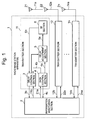
- Fig. 1 is a diagram showing a configuration of a radio base station apparatus according to an embodiment of the present invention.
- a radio base station apparatus 1 includes an information monitoring section 2 and a number n of transmitter sections 11, 12 to 1n.
- Each of the transmitter sections 11 to 1n includes a delay control section 3, a data control section 4, a delay adjustment section 5, and an RF (Radio Frequency) section 6.
- RF Radio Frequency
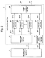
- Fig. 2 is a diagram showing a configuration of the data control section 4 shown in Fig. 1.
- the data control section 4 includes a main signal control section 41, spreading sections 421 to 42n, an adjustment signal control section 45, and a spreading section 46, and an adding and combining section 44.
- the information monitoring section 2 monitors at all times an operation status of the data control section 4 of each of the transmitter sections 11 to In. According to the operation status, the information monitoring section 2 controls the adjustment signal control section 45 of the data control section 4.
- the adding and combining section 44 outputs a multiplexed signal (4a) obtained by multiplexing a spread delay adjustment signal (46a) with spread main signals (421a to 42na).
- the multiplexed signal (4a) goes through the delay adjustment section 5 and the RF section 6, and is outputted via an antenna element (21 to 2n).
- the delay control section 3 compares the signal (4b) multiplexed with the delay adjustment signal in the data control section 4 with a feedback signal (6b) of a transmitting signal detected from the RF section 6 to thereby calculate a transmission delay time.
- the feedback signal (6b) from the RF section 6 is an analog signal detected immediately before being transmitted via the antenna.
- the delay control section 3 converts the signal (6b) into a digital signal through analog-to-digital conversion processing.
- Fig. 1 is a diagram showing a configuration of an embodiment of the present invention.
- a radio base station apparatus 1 includes an information monitoring section 2 and a number n of transmitter sections 11 to In which are monitored by the information monitoring section 2.
- the number n of transmitter sections 11 to In shown in Fig. 1 have the same configuration.
- An internal configuration is shown only for the transmitter section 11.
- the transmitter section 11 includes a delay control section 3, a data control section 4, a delay adjustment section 5, an RF section 6, and an antenna element 21.
- the information monitoring section 2 monitors the operation status of the transmitter sections 11 to 1n, and according to the operation status, controls a data control section 4 to perform a multiplexing processing of an adjustment signal.
- the delay control section 3 calculates a delay time adjustment value. Based on the delay time adjustment value calculated by the delay control section 3, the delay adjustment section 5 adjusts a transmission delay time. This adjustment is performed so that the transmitter sections 11 to In in the radio base station apparatus 1 have the same transmission delay time value.
- the delay-adjusted data 5a from the delay adj ustment section 5 is inputted to the RF section 6.
- the signal inputted to the RF section 6 is converted into an analog data, and then the frequency of the signal is up-converted into a frequency band used for transmission. After the up-conversion, the signal is divided into a modulating signal (11a) transmitted as a radio wave via the antenna element 21 and a signal (6b) used in the delay control section 3.
- the RF section 6 includes a digital-to-analog converter (DAC) (not shown), a mixer (a circuit having a local oscillator andaphaseshifter, and generating a quadrature-modulated signal by use of a mixer), a band-pass filter (BPF), an amplifier, an AGC (Auto Gain Control) amplifier, and a coupler.
- the RF section has a known configuration in which the received signal is processed in the digital-to-analog converter (DAC), mixer, band-pass filter (BPF) and amplifier in this order, and then is outputted via the antenna.
- Fig. 2 is a diagram showing a configuration of the data control section 4.
- the data control section 4 includes a main signal control section 41, spreading sections 421 to 42n and 46, an adding and combining section 44, and an adjustment signal control section 45.
- the current operation information 4c is at all times supplied as information from the main signal control section 41 to the information monitoring section 2. Based on the information (the current operation information 4c), the information monitoring section 2 outputs control information 21a to the adjustment signal control section 45, whereby the transmission delay time is controlled in the transmitter section 11.
- Data (411 to 41n and 45a) received from the main signal control section 41 and adjustment signal control section 45 are inputted to the spreading sections 421 to 42n and 4 6, respectively.
- Spread data (421a to 42na and 46a) received from the spreading sections 421 to 42n and 46) are inputted to the adding and combining section 44 to be multiplexed.
- the multiplexed data (4a) from the adding and combining section 44 is inputted to the delay adjustment section 5, and the multiplexed data (4b) is also inputted to the delay control section 3.
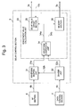
- Fig. 3 is a diagram showing a configuration of the delay control section 3 shown in Fig. 1.
- the delay control section 3 includes a waveform shaping unit 31, a divider unit 32, and a adjustment value calculation unit 33.
- the waveform shaping unit 31 performs an analog-to-digital conversion of a signal (6b) received from the RF section 6, and shapes the waveform.
- the divider unit 32 divides the multiplexed signal received from the data control section 4.
- the adjustment value calculation unit 33 calculates a delay time introduced by a signal path from the data control section 4 to the RF section 6 to supply a delay time adjustment value.
- the adjustment value calculation unit 33 includes a waveform comparator unit 34, a delay value offset section 35, and a memory section (36).
- the waveform comparator unit 34 compares a signal sent from the RF section 6 (i.e. an output signal 31a from the waveform shaping unit 31) with a signal sent from the data control section 4 (i.e. an output signal 32a from the divider unit 32). Based on a value obtained from the comparison, the delay value offset section 35 supplies an adjustment value 3a used to control the delay adjustment section 5.
- the memory section 36 stores the delay time information of the transmitter section 11. Also, the memory section 36 has a function of outputting transmission delay information 11b to the information monitoring section 2.
- the present invention is applied to a transmitter section of the radio base station apparatus 1 using CDMA technique.
- the radio base station apparatus 1 has a number n (n: an integer of 2 or more) of antenna elements 21 to 2n.
- the antennas has a transmit diversity configuration for each pair.
- the transmitter sections 11 and 12 constitute a transmit diversity system.
- the information monitoring section 2 has a function of integrally monitoring the operation status of each transmitter section 11 to In to collect a total transmitting power value (4c) and transmission delay time information (11b) to thereby control the delay control section 3 and data control section 4.
- CDMA Code Division Multiple Access
- eachuserdata (411 to 41n) assigned by the main signal control section 41 is supplied to each spreading section 421 to 42n, is subjected to a coding processing, and then is subjected to a multiplex processing in the adding and combining section 44.
- the multiplexed data (4a) goes through the delay adjustment section 5, is inputted to the RF section 6, and is subjected to a D/A conversion. Then, the frequency and power of the data signal is processed for transmission, and the resultant signal is transmitted via the antenna 21.
- the multiplexed data (4a) thus outputted can have a large peak value according to the combined data.
- signal level is limited in digital stage before the signal is converted from digital into analog and supplied into analog stage.
- the peak value Due to the amplitude limitation processing, the peak value is rounded up to the amplitude limitation value. Consequently, it can be difficult to identify the peak point.
- the probability of peak generation varies according to the combination of coded data, modulation method, and amplitude limitation method. Consequently, it can be more difficult to identify the peak point.
- the main signal control section 41 shown in Fig. 2 manages the number of users, transmitting power, code, etc, each of which are assigned to the transmitter section 11.
- the main signal control section 41 supplies the current value of total transmittingpower andunusedcode information to the information monitoring section 2.
- the information monitoring section 2 supplies prescribed amplitude information and code information to the adjustment signal control section 45.
- the adjustment signal control section 45 Based on the supplied code information, the adjustment signal control section 45 generates a adjustment signal.
- the adjustment signal has a specific waveform pattern.
- the adjustment signal control section 45 outputs a predetermined signal to the spreading section 46.
- the adding and combining section 44 multiplexes the spread main signals 421a to 42na with the spread signal 46a.
- the information monitoring section 2 receives the total-transmitting power information (4c) as one of the input signals from the data control sections 4, and monitors the value.
- the information monitoring section 2 supplies to the adjustment signal control section 45 of the data control section 4 an instruction such that the adjustment signal control section 45 outputs a signal having a specific waveform pattern, so that the transmitting power corresponding to the remaining 60 % or so is assigned.
- a code' is also assigned to this signal.
- the multiplexed signal outputted from the adding and combining section 44 looks similar to an ordinary signal obtained by multiplexing signals of a number n of users. Accordingly, it is possible to transmit this signal as a radio wave via the antenna element without having any influence on the operation status.
- the information monitoring section 2 sends the instruction to cause the adjustment signal to be outputted. Accordingly the amplitude fluctuations of the adjusted signal having specific pattern becomes predominant in outputted signal. Thus, the waveform comparison performed when the transmission delay time is calculated is made easy.
- the signal 4a is outputted from the data control section 4 to the delay adjustment section 5.
- the delay adjustment section 5 controls the delay time of the inputted signal 4a with an accuracy of 1/4 chips or more according to the adjustment value supplied from the delay control section 3, and outputs the resultant signal to the RF section 6.
- the RF section 6 converts the digital data into an analog signal.
- the frequency and power of the converted analog signal is converted for transmission, and then is outputted as a radio wave via the antenna element 21.
- the RF section 6 has a function of outputting the feedback signal 6b to the delay control section 3 via the coupler.
- the delay control section 3 compares the signal 4b from the data control section 4 with the signal 6b from the RF section 6 to thereby calculate the delay time.
- the signal 4b from the data control section 4 is inputted to the divider unit 32, and then is outputted to the adjustment value calculation unit 33 and waveform shaping unit 31.
- the signal 6b from the RF section 6 is inputted to the waveform shaping unit 31 (including an analog-to-digital converter and a wave detector), and is converted into digital data, and then, if necessary, is waveform-shaped based on information 32b from the divider unit 32, and is inputted to the adjustment value calculation unit 33.
- the feedback signal (6b) of the transmitting signal supplied from the RF section 6 to the waveform shaping unit 31 has a high frequency.
- the waveform of the signal can be distorted. Accordingly, there is included a complementary function using the waveform information 32b.
- an active range and a zero range are usually determined by use of a threshold value relative to the detected value.
- the values included in the active range are raised to a peak value. In practice, however, it is expected that the active range and zero range can not be accurately determined due to the performance of the detector, etc. Thus, the waveform information is used to minimize the error in the determination.
- the waveform comparator unit 34 compares the multiplexed signal 32a from the data control section 4 with a signal 31a (a signal obtained by digitalizing the feedback signal 6b from the RF section 6) to thereby calculate the delay time.
- the memory section 36 saves a calculated absolute delay time 34b, and at the same time supplies the information to the information monitoring section 2.
- the delay value offset section 35 controls a delay offset value with respect to the absolute delay time 34a calculated by the waveform comparator unit 34, and outputs the information.
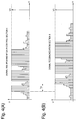
- the waveform comparator unit 34 compares the multiplexed signal 32a (refer to Fig. 4 (A)) from the data control section 4 with the signal 31a (refer to Fig. 4 (B)) obtained by digitalizing the feedback signal 6b from the RF section 6. At this time, a waveform comparison is performed with an accuracy of 1/4 chips or more to calculate an absolute delay time Td (refer to Fig. 4). The calculated absolute delay time Td is saved into the memory 36.
- the reason why the required accuracy for the delay time calculation is set to 1/4 chips or more is as follows; in a transmit diversity configuration, in order to achieve a transmit diversity effect, for example, at a chip rate of 3.84 Mcps (mega chip/sec), the transmission delay time between the antenna elements must be 1/4 chips or less.
- the data saved in the memory section 36 is monitored by the information monitoring section 2.
- the information monitoring section 2 controls the delay value offset section 35 of the adjustment value calculation unit 33 based on the delay offset information 21a so that the transmission delay time of each transmitter section 11 to In has the same value for all the transmitter sections or for each pair of the transmitter sections, whereby the information monitoring section 2 determines the adjustment value to be supplied to the delay adjustment section 5.
- the inventive method adjusts the transmission delay time within the radio base station apparatus, with the operation status taken into consideration and without interrupting the service, to thereby make it possible to implement a high-precision location detection.
Landscapes
- Engineering & Computer Science (AREA)
- Computer Networks & Wireless Communication (AREA)
- Signal Processing (AREA)
- Mobile Radio Communication Systems (AREA)
- Transmitters (AREA)
Applications Claiming Priority (2)
| Application Number | Priority Date | Filing Date | Title |
|---|---|---|---|
| JP2004093530 | 2004-03-26 | ||
| JP2004093530A JP4449528B2 (ja) | 2004-03-26 | 2004-03-26 | 遅延時間補正装置と方法並びに無線基地局装置 |
Publications (1)
| Publication Number | Publication Date |
|---|---|
| EP1580904A1 true EP1580904A1 (de) | 2005-09-28 |
Family
ID=34858523
Family Applications (1)
| Application Number | Title | Priority Date | Filing Date |
|---|---|---|---|
| EP20050006257 Withdrawn EP1580904A1 (de) | 2004-03-26 | 2005-03-22 | Verfahren und Vorrichtung zur Anpassung der Zeitverzögerung und Basisstation dafür |
Country Status (3)
| Country | Link |
|---|---|
| US (1) | US7489737B2 (de) |
| EP (1) | EP1580904A1 (de) |
| JP (1) | JP4449528B2 (de) |
Cited By (2)
| Publication number | Priority date | Publication date | Assignee | Title |
|---|---|---|---|---|
| WO2008057014A1 (en) * | 2006-11-08 | 2008-05-15 | Telefonaktiebolaget L M Ericsson (Publ) | Delay control using transmission diversity |
| WO2012152929A1 (en) * | 2011-05-12 | 2012-11-15 | St-Ericsson Sa | Time delay estimation |
Families Citing this family (2)
| Publication number | Priority date | Publication date | Assignee | Title |
|---|---|---|---|---|
| US7142830B2 (en) * | 2001-09-19 | 2006-11-28 | Nokia Corporation | Adaptive transceiver system |
| JP4463780B2 (ja) * | 2005-06-14 | 2010-05-19 | 株式会社エヌ・ティ・ティ・ドコモ | 送信装置および送信方法 |
Citations (2)
| Publication number | Priority date | Publication date | Assignee | Title |
|---|---|---|---|---|
| EP0776099A2 (de) * | 1995-11-21 | 1997-05-28 | AT&T Corp. | Kodemultiplexvielfachzugriffsmobilfunksystem |
| EP1217779A1 (de) * | 2000-12-22 | 2002-06-26 | Telefonaktiebolaget L M Ericsson (Publ) | Verzögerungssteuerregelung in einem digitalen Funkübertragungssystem |
Family Cites Families (6)
| Publication number | Priority date | Publication date | Assignee | Title |
|---|---|---|---|---|
| JP3305877B2 (ja) * | 1994-06-23 | 2002-07-24 | 株式会社東芝 | スペクトラム拡散無線通信システムおよびこのシステムで使用される無線通信装置 |
| US5960028A (en) * | 1995-08-11 | 1999-09-28 | Sharp Kabushiki Kaisha | Spread spectrum communication system |
| JPH09214467A (ja) | 1995-11-21 | 1997-08-15 | Lucent Technol Inc | 符号分割多元接続無線ローカルループシステムにおいて使用される基地局および加入者局 |
| JP2002374193A (ja) | 2001-06-13 | 2002-12-26 | Nec Saitama Ltd | 送信ダイバーシチ遅延補正方式 |
| JP3631716B2 (ja) | 2001-11-22 | 2005-03-23 | 埼玉日本電気株式会社 | W−cdma無線基地局及びその遅延時間差補正方法 |
| JP2003258694A (ja) | 2002-03-05 | 2003-09-12 | Nec Saitama Ltd | W−cdma無線基地局及びその遅延時間補正方法 |
-
2004
- 2004-03-26 JP JP2004093530A patent/JP4449528B2/ja not_active Expired - Fee Related
-
2005
- 2005-03-22 EP EP20050006257 patent/EP1580904A1/de not_active Withdrawn
- 2005-03-23 US US11/087,219 patent/US7489737B2/en not_active Expired - Fee Related
Patent Citations (2)
| Publication number | Priority date | Publication date | Assignee | Title |
|---|---|---|---|---|
| EP0776099A2 (de) * | 1995-11-21 | 1997-05-28 | AT&T Corp. | Kodemultiplexvielfachzugriffsmobilfunksystem |
| EP1217779A1 (de) * | 2000-12-22 | 2002-06-26 | Telefonaktiebolaget L M Ericsson (Publ) | Verzögerungssteuerregelung in einem digitalen Funkübertragungssystem |
Cited By (3)
| Publication number | Priority date | Publication date | Assignee | Title |
|---|---|---|---|---|
| WO2008057014A1 (en) * | 2006-11-08 | 2008-05-15 | Telefonaktiebolaget L M Ericsson (Publ) | Delay control using transmission diversity |
| WO2012152929A1 (en) * | 2011-05-12 | 2012-11-15 | St-Ericsson Sa | Time delay estimation |
| CN103650604A (zh) * | 2011-05-12 | 2014-03-19 | 意法爱立信有限公司 | 时间延迟估计 |
Also Published As
| Publication number | Publication date |
|---|---|
| US7489737B2 (en) | 2009-02-10 |
| JP2005286416A (ja) | 2005-10-13 |
| JP4449528B2 (ja) | 2010-04-14 |
| US20050213639A1 (en) | 2005-09-29 |
Similar Documents
| Publication | Publication Date | Title |
|---|---|---|
| JP3078330B2 (ja) | Cdma通信システムにおける遠隔送信機電力制御 | |
| KR101325382B1 (ko) | 가변 다중 속도 통신 시스템용 고속 적응 전력 제어 방법 및 시스템 | |
| KR100346204B1 (ko) | 수신기 이득의 계측 및 안테나 임피던스 매칭의 측정을위한 통합 시스템 및 그 동작 방법 | |
| CN1083680C (zh) | 用于测试时分多址无线通信系统中基站的方法和装置 | |
| US6567459B1 (en) | Power control in mobile communications system | |
| EP0645940A1 (de) | Basisstationsanordnung und Mobilstationsanordnung in mobilen Kommunikationssystemen | |
| US20080045271A1 (en) | Transmit power control | |
| KR20010013848A (ko) | 무선 통신 장치 및 전송 비율 제어 방법 | |
| KR20020026593A (ko) | 무선 주파수 증폭기에 대한 적응성 프리리미터 | |
| US7729727B2 (en) | Aligning radio base station node transmission timing on multiple transmit paths | |
| WO2001082511A2 (en) | Frequency selective rf output power calibration using digital and analog power measurements for use in a cellular telecommunications system | |
| EP0860057B1 (de) | Verfahren und anordnung zur leistungsregelung in einem mobilen telefonsystem | |
| US7489737B2 (en) | Delay adjustment device and method, and radio base station apparatus | |
| CN1402913B (zh) | 无线通信系统中发射功率调整的方法 | |
| EP1156600A1 (de) | Cdma empfänger und cdma verfahren | |
| KR20010101042A (ko) | 무선 송신 장치, 기지국 장치, 통신 단말 장치 및 송신 다이버시티 방법 | |
| TWI430587B (zh) | 發射器延遲及相位調整技術 | |
| EP1569350B1 (de) | Leistungsbegrenzungsvorrichtung und ein diese verwendender digitaler funksender | |
| JP2002374193A (ja) | 送信ダイバーシチ遅延補正方式 | |
| US20040131027A1 (en) | Method for gain control and corresponding receiving unit | |
| KR20050097999A (ko) | 링크, 스테이션 및 통신 시스템의 두개의 채널들의 전송출력들을 조정하는 방법 | |
| CN1241074A (zh) | 码分多址通信系统中发射设备的发送功率控制装置 | |
| HK1083278A (en) | Power limit device and digital radio transmitter using the same |
Legal Events
| Date | Code | Title | Description |
|---|---|---|---|
| PUAI | Public reference made under article 153(3) epc to a published international application that has entered the european phase |
Free format text: ORIGINAL CODE: 0009012 |
|
| 17P | Request for examination filed |
Effective date: 20050721 |
|
| AK | Designated contracting states |
Kind code of ref document: A1 Designated state(s): AT BE BG CH CY CZ DE DK EE ES FI FR GB GR HU IE IS IT LI LT LU MC NL PL PT RO SE SI SK TR |
|
| AX | Request for extension of the european patent |
Extension state: AL BA HR LV MK YU |
|
| AKX | Designation fees paid |
Designated state(s): DE FI GB SE |
|
| 17Q | First examination report despatched |
Effective date: 20090402 |
|
| STAA | Information on the status of an ep patent application or granted ep patent |
Free format text: STATUS: THE APPLICATION HAS BEEN WITHDRAWN |
|
| 18W | Application withdrawn |
Effective date: 20100903 |