EP1580831A2 - Pile à combustible de type polyélectrolyte à l'état solide - Google Patents
Pile à combustible de type polyélectrolyte à l'état solide Download PDFInfo
- Publication number
- EP1580831A2 EP1580831A2 EP05006162A EP05006162A EP1580831A2 EP 1580831 A2 EP1580831 A2 EP 1580831A2 EP 05006162 A EP05006162 A EP 05006162A EP 05006162 A EP05006162 A EP 05006162A EP 1580831 A2 EP1580831 A2 EP 1580831A2
- Authority
- EP
- European Patent Office
- Prior art keywords
- honeycomb
- fuel cell
- fuel
- solid
- channel
- Prior art date
- Legal status (The legal status is an assumption and is not a legal conclusion. Google has not performed a legal analysis and makes no representation as to the accuracy of the status listed.)
- Granted
Links
Images


Classifications
-
- H—ELECTRICITY
- H01—ELECTRIC ELEMENTS
- H01M—PROCESSES OR MEANS, e.g. BATTERIES, FOR THE DIRECT CONVERSION OF CHEMICAL ENERGY INTO ELECTRICAL ENERGY
- H01M8/00—Fuel cells; Manufacture thereof
- H01M8/24—Grouping of fuel cells, e.g. stacking of fuel cells
- H01M8/241—Grouping of fuel cells, e.g. stacking of fuel cells with solid or matrix-supported electrolytes
-
- H—ELECTRICITY
- H01—ELECTRIC ELEMENTS
- H01M—PROCESSES OR MEANS, e.g. BATTERIES, FOR THE DIRECT CONVERSION OF CHEMICAL ENERGY INTO ELECTRICAL ENERGY
- H01M8/00—Fuel cells; Manufacture thereof
- H01M8/02—Details
-
- H—ELECTRICITY
- H01—ELECTRIC ELEMENTS
- H01M—PROCESSES OR MEANS, e.g. BATTERIES, FOR THE DIRECT CONVERSION OF CHEMICAL ENERGY INTO ELECTRICAL ENERGY
- H01M8/00—Fuel cells; Manufacture thereof
- H01M8/002—Shape, form of a fuel cell
-
- H—ELECTRICITY
- H01—ELECTRIC ELEMENTS
- H01M—PROCESSES OR MEANS, e.g. BATTERIES, FOR THE DIRECT CONVERSION OF CHEMICAL ENERGY INTO ELECTRICAL ENERGY
- H01M8/00—Fuel cells; Manufacture thereof
- H01M8/10—Fuel cells with solid electrolytes
- H01M8/1004—Fuel cells with solid electrolytes characterised by membrane-electrode assemblies [MEA]
-
- Y—GENERAL TAGGING OF NEW TECHNOLOGICAL DEVELOPMENTS; GENERAL TAGGING OF CROSS-SECTIONAL TECHNOLOGIES SPANNING OVER SEVERAL SECTIONS OF THE IPC; TECHNICAL SUBJECTS COVERED BY FORMER USPC CROSS-REFERENCE ART COLLECTIONS [XRACs] AND DIGESTS
- Y02—TECHNOLOGIES OR APPLICATIONS FOR MITIGATION OR ADAPTATION AGAINST CLIMATE CHANGE
- Y02E—REDUCTION OF GREENHOUSE GAS [GHG] EMISSIONS, RELATED TO ENERGY GENERATION, TRANSMISSION OR DISTRIBUTION
- Y02E60/00—Enabling technologies; Technologies with a potential or indirect contribution to GHG emissions mitigation
- Y02E60/30—Hydrogen technology
- Y02E60/50—Fuel cells
Definitions
- the present invention generally relates to a solid-state polyelectrolyte type fuel cell usable as an installed- or transportable-use small power source, and more particularly to a solid-state polyelectrolyte type fuel cell including a honeycomb structure formed from a solid-state polyelectrolyte membrane to have multiple honeycomb channels, with a fuel electrode or air electrode being formed on the inner wall of each the honeycomb channels and the honeycomb channels being disposed alternately for the fuel and air electrodes to adjoin each other.
- the fuel cell of this solid-state polyelectrolyte type is easy to assemble because of its lineup of components. Since a polymer membrane is used as the electrolyte, the fuel cell can easily be designed compact. Also, this fuel cell can operate at a temperature of about 100°C, which is rather lower than those of fuel cells of other types. Therefore, the solid-state polyelectrolyte type fuel cell has recently gained the spotlight as a small power source for installed or transportable use.
- an electrode layer as a fuel or air electrode is formed on either side of a sheet-like polyelectrolyte membrane.
- a carbon fiber felt layer is disposed as a diffusion zone on the outer surface of the electrode layer, and the carbon fiber felt is sandwiched at the outer surface thereof between two plate-shaped separators (bipolar plate) to form a so-called planar "unit cell".
- a plurality of such unit cells is stacked one on the other with a packing and sealing member being interposed between them to form a cell stack.
- a coolant channel is formed as necessary between the separators of each unit cell, and the temperature of the cell stack is controlled with a coolant.
- the reason why the solid-state polyelectrolyte type fuel cell uses the stack structure as above is that the voltage of each unit cell is as low as 1 V or less and a stack of multiple unit cells connected in series to each other will be able to provide a high voltage when the fuel cell is practically used. Also, such stacks may be connected in parallel to each other to form a large-capacity cell.
- the conventional fuel cell having the aforementioned planar cell stack structure uses a separator to isolate a fuel and oxidizing gas from each other. Since the separator has a large volume and accounts for a considerable part of the volume of the solid-state polyelectrolyte type fuel cell, it should be designed thin and compact for a compact design of the fuel cell itself. However, if the gas channel is formed shallow and narrow for the purpose of such a compact design, the pressure loss will be caused to be larger with a result that the fuel and oxidizing gas will not flow smoothly through the respective channels. Also, if the gas channel is formed thin, the gas will possibly leak and also its self-holding strength will be lower. Therefore, the solid-state polyelectrolyte type fuel cell having the planar cell stack structure cannot be designed so compact (cf. the Japanese unexamined patent publication (KOKAI) No. 2003-45456 or 2003-151611).
- the electrolyte membrane itself is designed cylindrical and there is provided a mechanism to isolate a fuel and oxygen from each other, which makes it unnecessary to use any aforementioned separator.
- the cylindrical membrane is formed from a soft polymer material, it cannot securely hold itself, is easily deformable and cannot assure any satisfactory channel for circulation of a gas or liquid such as a fuel, oxidizing gas or the like.
- multiple cylindrical membranes should be bundled together. In this case, the fuel and oxidizing gas inlets and outlets, power lead-out terminal, coolant inlet and outlet, if any provided when it is necessary to control the temperature, etc. have to be disposed very elaborately.
- a solid-state electrolyte formed from a ceramic material is molded into a honeycomb structure, an electrode is formed on the isolation wall of each structure, each of a fuel and oxidizing gas is circulated through a specific one of such channels.
- both the axial end faces of the electrolyte-made honeycomb structure are held tight between a power terminal and a push plate having a gas inlet/outlet function.
- the shape of this fuel cell has to be retained with only the strength of the electrolyte-made honeycomb structure itself.
- this type of fuel cell may not be formed from a soft material such as a solid-sate polyelectrolyte membrane, and the push plate with the function of fuel and oxidizing gas introduction/drainage is poor in sealing performance with a possibility that a fuel and oxidizing gas will mix together.
- the cross section of the channel is triangular, rectangular, hexagonal or polygonal shape, and the honeycomb channel has any one, or a combination of two or more, of the cross sections.
- the honeycomb structure is formed from a corrugated joined assembly.
- the honeycomb structure is a extrusion-molded multi-cell structure having a polygonal cross section, and a material for forming each of the fuel and air electrodes is precipitated or deposited on either side of the isolation wall between the fuel and air electrode channels by electroless plating using a plating solution containing a metal complex.
- the above solid-state polyelectrolyte type fuel cell according to the present invention is formed from an aggregate of a plurality of the honeycomb structures each as a unit element, disposed in series to each other axially of the honeycomb channel.
- the above solid-state polyelectrolyte type fuel cell according to the present invention is formed from an aggregate of a plurality of the honeycomb structures each as a unit element, disposed in parallel to each other in a direction perpendicular to the axis of the honeycomb channel.
- the above solid-state polyelectrolyte type fuel cell according to the present invention is formed from a combination of the aggregate of a plurality of the honeycomb structures each as a unit element, disposed in series to each other axially of the honeycomb channel, and the aggregate of a plurality of the honeycomb structures each as a unit element, disposed in parallel to each other in a direction perpendicular to the axis of the honeycomb channel.
- the honeycomb structure or aggregate of the honeycomb structures at least one of the outer surface (lateral side), both axial open end faces and honeycomb channel inside is reinforced with a shape-retaining member.
- the shape-retaining member is formed from more than one selected from resin, metal, inorganic elementary substance and a composite of these materials, and a member provided inside the honeycomb channel is formed from a porous material having through-pores.
- the honeycomb structure has the fuel electrodes thereof electrically connected to each other at one of the open end faces and the air electrodes thereof electrically connected to each other at the other open end face, for the fuel and air electrodes to be wired in parallel to each other inside the unit element.
- the honeycomb structure has the adjacent fuel and air electrodes thereof electrically connected to each other at both the open end faces and the fuel and air electrodes thereof electrically connected to each other at the other open end face, for the fuel and air electrodes to be is provided inside the honeycomb channel wired in series to each other inside the unit element.
- the present invention provides a solid-state polyeletrolyte fuel cell in which the gas-tightness can easily be kept and the fuel and air electrodes can be separated from each other without using any separator. Further, since the necessity of no separator necessarily leads to occurrence of no electrical resistance such as contact resistance, the present invention provides a solid-state polyelectrolyte type fuel cell extremely high in efficiency of power generation, compact and lightweight.
- the solid-state polyelectrolyte type fuel cell according to the present invention can operate well with using, as necessary, only a temperature controlling water-cooled tube and coolant channel formed from a part of the honeycomb channel. Therefore, the present invention can implement the lightweight design and low manufacturing and running costs, which are the drawbacks of the conventional stacked type fuel cell.
- the solid-state polyelectrolyte type fuel cell according to the present invention includes a honeycomb structure as a body.
- This honeycomb structure is formed by bonding together sheet-like solid-state polyelectrolyte membranes excellent in characteristics such as durability against oxidation-reduction reaction, proton conductivity, repeated-use durability, etc. or by extrusion molding of a solid-state polyelectrolytic material.
- the honeycomb structure of the above first type is formed as will be described below.
- a sheet of a solid-state polyelectrolyte such as Nafion (trademark: Du Pont) or Flemion (trademark: Asahi Glass) is prepared.
- An electrode material is produced from platinum or an alloy of platinum and ruthenium carried by a carbon black such as Vulcan(trademark: Cabot).
- the electrode material and a commercially available 5% Nafion are mixed together to provide a mixture paste.
- the solid-state polyelectrolyte sheet is coated on the surface thereof with the mixture paste by printing, and then dried.
- honeycomb structure having a plurality of honeycomb channels whose cross section is triangular.
- the honeycomb structure of the above second type is formed as will be described below.
- a honeycomb structure having a plurality of honeycomb channels whose cross section is polygonal shape is formed directly by extrusion molding.
- a solution of a solid-state polyelectrolytic material is first extruded to mold a plurality of honeycomb channels integrally with each other all at once.
- the solid-state polyelectrolytic material should be highly workable and able to form a thin isolation wall in addition to having the aforementioned excellent characteristics such as durability against oxidation-reduction reaction, proton conductivity, durability against repeated use, etc.
- a preferable solid-state polyelectrolytic material is an ion-exchange resin, for example, (1) a fluorocarbon resin of perfluorosulfonic acid origin, (2) dry mixture of perfluorosulfonic acid origin and silica sol, (3) a heat-resistant hydrocarbon polymer (simple substance) obtained by sulfonating a polysulfone, polybenzimidazole, polyetheretherketone or the like, (4) a polymer blend of two or more of the (3), (5) a graft polymer of the (3), or (6) a composite of any of the (1) to (5) and inorganic fine particles.
- each unit element (honeycomb structure) of a honeycomb aggregate has either a fuel electrode or air electrode formed on the surface of a part (solid-state polyelectrolyte membrane) forming the isolation wall of the unit element.
- Each of the honeycomb cells provides either a fuel or air channel depending upon whether the electrode on its wall is a fuel electrode or air electrode, with adjacent honeycomb channels being of different polarities, respectively.
- the fuel electrodes are electrically wired to each other at one of the open end faces while the air electrodes are electrically wired to each other at the other open end face.
- the electrodes of the same type are connected in parallel to each other, and the fuel electrode serves as an anode while the air electrode (oxidizing gas electrode) serves as a cathode (see Fig. 6(a)).
- the adjacent fuel and air electrodes are connected to each other at both the open end faces.
- the electrodes of the same type are connected in series to each other, and one of the open end faces of the unit element serves as an anode while the other open end serves as a cathode (see Fig. 6(b)).
- the electrodes are connected to each other as above by a combination of a press-fittable carbon-made connecting terminal and a sheathed copper wire, a combination of a metal-pin connecting terminal with a corrosion-resistant coating applied by metal plating or the like and a sheathed metal wire, or the like.
- the electrodes are connected either in series or in parallel at each end face depending upon the circuit design (voltage and current) or these two ways of connection may be adopted in combination as the case may be.
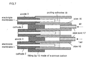
- Fig. 7 is an axial-sectional view of the pipe units connecting the unit elements (honeycomb structure) to each other.
- each pipe unit includes a fitting jig 15 formed from a porous carbon, a pipe 16 formed from carbon or metal and a joint 17.
- the pipe is inserted in each of the fuel and electrode channels.
- An adhesive 18 should preferably be filled by potting in the space between adjacent pipe units 16 to gang the pipes 16 together.
- the fuel electrode channels are connected and communicated with each other (the air electrode channels are also connected and communicated with each other) so that air (oxidizing gas) and fuel fluid (hydrogen or methanol) will flow through a series of fuel electrode channels and a series of air electrode channels, respectively.
- the pipe should preferably be a prismatic one.
- the pipe may have a columnar section, such as conical, pyramidal, cylindrical or similar sectional shape.
- the fitting jig 15 made of a porous carbon is put into contact with a cathode electrode 2 or anode electrode 3 formed on the surface of an electrolyte membrane 1. Also, the adjacent pipes are coupled with an adhesive layer to each other and thus fixed to form a pipe gang.
- air or fuel can be supplied to the cathode electrode 2 or anode electrode 3 in the honeycomb structure through the pipe 16 via the pipe joint 17 also included in the pipe unit. Forced to flow in the reverse direction, air or fuel gas can drain off to outside the honeycomb structure.
- a plurality of pipe joints may of course be connected in series or in parallel.
- the electrodes can be electrically wired directly from the fitting jig 15 or via an electrically conductive adhesive.
- porous carbon-made fitting jig 15, if formed long along the axis of channel, can serve as an intra-channel support.
- honeycomb structure according to the present invention is formed mainly from the solid-state polyelectrolyte membrane, its shape retention is limited, more than at least one of the outer surface (outer wall), end face of the pipe at the axial opening (at the pipe-gang side) and honeycomb-channel inner wall should preferably be reinforced with a shape-retaining member.
- the shape-retaining member may be any one of inorganic materials such as ceramic, metal, alloy, resin and a plate or column formed from a combination of any selected ones of such materials.
- the shape-retaining member should preferably be a resin or ceramic which has a high electrical insulation resistance and strength of structure, while for reinforcing the honeycomb-channel inner wall, an electrically conductive carbonaceous material or a metal with corrosion-protection coating is effectively usable to maintain an internal pressure, prevent gas leak and retain the cell shape.
- the ceramic used as the shape-retaining member may be one selected from general-purpose ceramics such as alumina, mullite, glass, carbon, silicon nitride, zirconia, cordierite and porcelain
- the metal may be one of general-purpose metals including aluminum, stainless steel, iron, copper, titanium and nickel, or the alloy thereof
- the resin may be selected from general-purpose resins such as polypropylene, polyethylene or acrylic, and fluorocarbon resins and engineering plastics including polyimide, polyamide and polycarbonate.
- these materials should be processed (by applying a nonconductive layer or by plating gold, for example) for assuring the heat resistance and corrosion resistance at an operating temperature and in an atmosphere at the time of power generation and for blocking any eluates such as ions which will degrade the electrolyte membrane.
- the corrugated honeycomb structure or the honeycomb structure whose channels are formed integrally by extrusion molding, is used as a unit element.
- the solid-state polyelectrolyte type fuel cell can be embodied mainly in the following types.
- such a unit element is used as a monolith type as it is; secondly, a plurality of such unit elements is disposed in series to each other axially of their honeycomb channels; thirdly, a plurality of such unit elements is disposed in a bundle in parallel to each other in a direction perpendicular to the axis of their honeycomb channels; and fourthly, a plurality of such unit elements is disposed as an aggregated combination of the third and fourth types.
- the fuel electrodes are electrically connected to each other at the open end face of one of the unit elements and the air electrodes are electrically connected to each other at the open end face of the other unit element.
- two unit elements are electrically connected to each other at the end faces thereof for the fuel and air electrodes of each unit element to have the same polarity.
- the two unit elements By connecting the two unit elements to each other as above, their electrodes can be connected in parallel to each other, with the fuel electrode serving as an anode while the air electrode (oxidizing gas electrode) serves as an cathode.
- each pipe unit since the unit elements (honeycomb channels) can be connected to each other via the pipe units, each pipe unit will enable a continuous gas supply and electrical connection between the unit elements simultaneously.
- the unit elements may be so connected to each other by providing, in the pipe unit shown in Fig. 7, another fitting jig 15 similar to the fitting jig provided at the left open end of the pipe 16 in place of the pipe joint 17 provided at the right open end of the pipe 16, and inserting the alternate fitting jig 15 into the end cell of the air electrode or fuel channel of another honeycomb structure as a unit element which is to be connected to these unit elements connected as above.
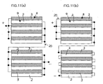
- the unit elements can be electrically wired to each other by repeating the connection as shown in Fig. 6 (also see Figs. 10(a) and 10(b)) and also they can be wired in series to each other (also see Figs. 11(a) and 11(b)).
- the wire is indicated with a reference numeral 20.
- a liquid such as methanol, ethanol or dimethyl ether
- DMFC direct methanol type fuel cell
- This type of fuel cell needs not any reformer to extract hydrogen from a fuel and any hydrogen container, and can solve the problems such as response to load fluctuation and starting loss.
- its system is so simple and compact that this type of fuel cell is advantageous in both manufacturing and running costs.
- the solid-state polyelectrolyte type fuel cell was produced as will be described below:
- the air electrode is formed as follows. Platinum-carrying carbon black (TEC10E50E, Pt in 50% by Tanaka Kikinzoku), 5% Nafion-117(trademark: Du-Pont) and butyl acetate were mixed together to produce a paste of 30% by weight in solid-content concentration.
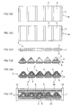
- This paste was printed in a pattern shown in Fig. 1(a) by screen printing on one surface 1a of a commercially available solid-state polyelectrolyte membrane 1 (SH-50, 50 ⁇ m thick by Asahi Glass). Then, the solid-state polyelectrolyte membrane 1 was dried at 80°C in an oven to form 15 ⁇ m-thick cathode catalyst layers 2 each being to serve as an air electrode.
- Pt-Ru-carrying carbon black (TEC61E54, Pt in 30.4% and Ru in 23.6% by Tanaka Kikinzoku), 5% Nafion-117 and butyl acetate were mixed together and conditioned to provide a paste of 35% by weight in solid-content concentration.
- This paste was printed in a pattern shown in Fig. 1(b) by screen printing on a surface 1b of the solid-state polyelectrolyte membrane 1, opposite to the cathode catalyst layer 2. Then, the solid-state polyelectrolyte membrane 1 was dried to form anode catalyst layers 3 each being to serve as a fuel electrode.
- a corrugated structure 7 was obtained in which the solid-state polyelectrolyte membrane 1 was sandwiched between the joined assemblies 4 and 4'.
- Three such corrugated structures 7 were stacked one on the other as shown, by way of example, in the cross-sectional view given in Fig. 2. It should be noted that 5% Nafion-117 was applied to the junction between the solid-state polyelectrolyte membranes to join them to each other.
- the corrugated structure 7 including the triangle pole-shaped jigs 5 was hot-pressed at a temperature of 130°C under a pressure of 10 MPa for 10 minutes.
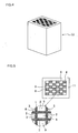
- the corrugated honeycomb structure 7 thus formed was 5 mm in length of one side of the triangular cross section, 15 ⁇ 20 mm in sectional area and 30 mm in length.
- each of the end openings of the honeycomb structure 7 there was fitted a pyramidal pipe coupling fuel electrode channels 8 or air electrode channels 9 to each other.
- the pyramidal pipes thus fitted were coupled to each other by potting with an epoxy adhesive to form the pipe gangs 10a and 10b.
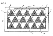
- the lateral sides of the corrugated honeycomb structure 7, except for both end faces, were reinforced with alumina shape-retaining plates 11.
- the circuit of this honeycomb structure was designed such that the air electrode channels 9 were connected in parallel to each other at one end of the honeycomb structure, while the fuel electrode channels 8 were connected in parallel to each other at the other end, as shown in Fig. 8.
- the solid-state polyelectrolyte type fuel cell was produced as will be described below:
- the honeycomb structure 12 was dried at 120°C for 1 hour, and then cut to a length of about 3 cm axially of the honeycomb channel.
- the honeycomb structure 12 formed from the solid-state polyelectrolyte membrane 1, thus formed, cannot retain its own shape unless appropriately processed.
- a 0.8 mm-thick shape-retaining plate 11 of a reinforcing polypropylene resin was attached with an adhesive to each of outermost sides of the honeycomb structure 12, and the shape-retaining plates 11 were joined at their corners to each other.
- the pipe unit as shown in Fig. 7 were inserted into the corresponding end openings of the honeycomb channels (fuel electrode channels 8 and air electrode channels 9) in the honeycomb structure 12, and they were connected to alternate ones as shown in Fig. 3.
- an aqueous solution of a mixture of 0.1 % boric sodium hydrate and 2% sodium hydrate was put into the honeycomb channel 8 serving as the fuel electrode to form the anode catalyst layer 3.
- a mixture of 0.1% chloroplatinic aqueous solution and platinum catalyst-carrying carbon black was put into the honeycomb channel 9 serving as the air channel to separate out the platinum inside the air electrode channel by chemical plating.
- the cathode catalyst layer 2 was formed.
- each of the honeycomb channels was washed with deionized water to remove unreacted substances.
- the fuel electrode channel 8 was filled with palladium-activated butyl liquid for electroless plating. After completion of a reaction at room temperature for 0.5 minute, the activated liquid was removed and the channel inside was dried. Then, a suspended mixture of Pt-Ru-carrying carbon black (TEC61E54, Pt in 30.4% and Ru in 23.6% by Tanaka Kikinnzoku), 0.1 % chloroplatinic aqueous solution and reductant liquid was supplied to the honeycomb channel 8 at a temperature of 30 ⁇ 2 °C and rate of 20 cc/min for reaction with each other to deposit the anode catalyst layer 3 on the inner wall of the honeycomb channel 8. Thereafter, the honeycomb channel 8 was washed and dried at 80°C for 0.5 hour. The cross-section and electrode arrangement of the honeycomb structure thus formed are shown in Fig. 5. The electrodes were connected in series to each other for each type of the channels.
- the fuel electrode channel 8 was filled with an aqueous solution of water and methanol in a molar ratio of 1 : 1 and air was supplied to the air electrode channel 9, to thereby form the DMFC (direct methanol fuel cell).
- the current-output characteristic of this DMFC was 8 mW/cm 2 at 40 mA per cell.
Landscapes
- Life Sciences & Earth Sciences (AREA)
- Engineering & Computer Science (AREA)
- Manufacturing & Machinery (AREA)
- Sustainable Development (AREA)
- Sustainable Energy (AREA)
- Chemical & Material Sciences (AREA)
- Chemical Kinetics & Catalysis (AREA)
- Electrochemistry (AREA)
- General Chemical & Material Sciences (AREA)
- Fuel Cell (AREA)
- Inert Electrodes (AREA)
Applications Claiming Priority (2)
| Application Number | Priority Date | Filing Date | Title |
|---|---|---|---|
| JP2004082734 | 2004-03-22 | ||
| JP2004082734 | 2004-03-22 |
Publications (3)
| Publication Number | Publication Date |
|---|---|
| EP1580831A2 true EP1580831A2 (fr) | 2005-09-28 |
| EP1580831A3 EP1580831A3 (fr) | 2006-06-07 |
| EP1580831B1 EP1580831B1 (fr) | 2008-06-18 |
Family
ID=34858374
Family Applications (1)
| Application Number | Title | Priority Date | Filing Date |
|---|---|---|---|
| EP05006162A Expired - Lifetime EP1580831B1 (fr) | 2004-03-22 | 2005-03-21 | Pile à combustible de type polyélectrolyte à l'état solide |
Country Status (6)
| Country | Link |
|---|---|
| US (1) | US20050208356A1 (fr) |
| EP (1) | EP1580831B1 (fr) |
| KR (1) | KR100760492B1 (fr) |
| CN (1) | CN100438184C (fr) |
| AT (1) | ATE398842T1 (fr) |
| DE (1) | DE602005007529D1 (fr) |
Families Citing this family (2)
| Publication number | Priority date | Publication date | Assignee | Title |
|---|---|---|---|---|
| WO2007096986A1 (fr) * | 2006-02-24 | 2007-08-30 | Ibiden Co., Ltd. | Dispositif de chauffage de face d'extremite, procede de sechage de la face d'extremite d'un assemblage en nid d'abeille et procede de production de structures en nid d'abeille |
| US8304136B2 (en) * | 2009-09-10 | 2012-11-06 | Samsung Electro-Mechanics Co., Ltd. | Solid oxide fuel cell and solid oxide fuel cell bundle |
Family Cites Families (8)
| Publication number | Priority date | Publication date | Assignee | Title |
|---|---|---|---|---|
| JPS60136175A (ja) * | 1983-12-26 | 1985-07-19 | Toshiba Corp | 燃料電池発電システム |
| US6291091B1 (en) * | 1997-12-24 | 2001-09-18 | Ballard Power Systems Inc. | Continuous method for manufacturing a Laminated electrolyte and electrode assembly |
| JPH11224677A (ja) * | 1998-02-10 | 1999-08-17 | Denso Corp | 固体高分子型燃料電池 |
| JP4236298B2 (ja) * | 1998-04-14 | 2009-03-11 | 東邦瓦斯株式会社 | ハニカム一体構造の固体電解質型燃料電池 |
| US6080501A (en) * | 1998-06-29 | 2000-06-27 | Motorola, Inc. | Fuel cell with integral fuel storage |
| GB9814121D0 (en) * | 1998-07-01 | 1998-08-26 | British Gas Plc | Separator plate for the use in a fuel cell stack |
| JP2002124273A (ja) * | 2000-10-18 | 2002-04-26 | Mitsubishi Rayon Co Ltd | 固体高分子型燃料電池とその製造方法及び固体高分子型燃料電池モジュール |
| AU2002230865A1 (en) * | 2000-10-30 | 2002-05-15 | Michael A. Cobb & Company | Solid oxide fuel cells stack |
-
2005
- 2005-03-16 KR KR1020050021970A patent/KR100760492B1/ko not_active Expired - Fee Related
- 2005-03-21 US US11/084,036 patent/US20050208356A1/en not_active Abandoned
- 2005-03-21 DE DE602005007529T patent/DE602005007529D1/de not_active Expired - Lifetime
- 2005-03-21 EP EP05006162A patent/EP1580831B1/fr not_active Expired - Lifetime
- 2005-03-21 AT AT05006162T patent/ATE398842T1/de not_active IP Right Cessation
- 2005-03-22 CN CNB2005100564293A patent/CN100438184C/zh not_active Expired - Fee Related
Also Published As
| Publication number | Publication date |
|---|---|
| DE602005007529D1 (de) | 2008-07-31 |
| US20050208356A1 (en) | 2005-09-22 |
| CN1838459A (zh) | 2006-09-27 |
| EP1580831A3 (fr) | 2006-06-07 |
| CN100438184C (zh) | 2008-11-26 |
| EP1580831B1 (fr) | 2008-06-18 |
| KR20060043715A (ko) | 2006-05-15 |
| ATE398842T1 (de) | 2008-07-15 |
| KR100760492B1 (ko) | 2007-10-04 |
Similar Documents
| Publication | Publication Date | Title |
|---|---|---|
| CN101981734B (zh) | 电化学电池及其相关膜 | |
| CA2516765C (fr) | Piles de cellules electrochimiques a membranes a collecteurs exterieurs | |
| USRE41577E1 (en) | High power density fuel cell stack using micro structured components | |
| US6511766B1 (en) | Low cost molded plastic fuel cell separator plate with conductive elements | |
| KR100976506B1 (ko) | 고체산화물 연료전지용 전극 지지체와 일체형 단위 셀 및이를 이용한 스텍 제작 방법 | |
| US20100068600A1 (en) | Fuel cell system | |
| US6677069B1 (en) | Sealless radial solid oxide fuel cell stack design | |
| EP2424028A2 (fr) | Bloc pour une pile à combustible à oxyde solide utilisant une structure tubulaire plate | |
| JP2007157724A (ja) | 固体酸化物燃料電池モジュール、及びこれを利用した燃料電池並びにその製作方法 | |
| US7150933B1 (en) | Method of manufacturing high power density fuel cell layers with micro structured components | |
| AU2001281220A1 (en) | Sealless radial solid electrolyte fuel cell stack design | |
| US6864010B1 (en) | Apparatus of high power density fuel cell layer with micro for connecting to an external load | |
| US20030186107A1 (en) | High performance fuel cells | |
| US20050282051A1 (en) | Integrated honeycomb solid electrolyte fuel cells | |
| CA2781095A1 (fr) | Pile a combustible capable de miniaturisation | |
| EP1580831B1 (fr) | Pile à combustible de type polyélectrolyte à l'état solide | |
| CA2568763C (fr) | Module de pile a combustible muni d'un corps creux permeable a l'eau et pile a combustible comprenant un tel module | |
| JP2004119189A (ja) | 燃料電池 | |
| US6989215B1 (en) | Apparatus of high power density fuel cell layer with micro structured components | |
| CN116072944B (zh) | 一种单堆兆瓦级燃料电池 | |
| WO2024225534A1 (fr) | Cellule à oxyde solide | |
| JP2005322621A (ja) | 固体高分子電解質型燃料電池 | |
| KR20050010653A (ko) | 막전극 접합체, 그를 포함하는 연료 전지 및 그 제조 방법 | |
| KR101065376B1 (ko) | 연료 전지 시스템, 이에 사용되는 스택 및 세퍼레이터 | |
| CN117059859A (zh) | 一种电堆阵列 |
Legal Events
| Date | Code | Title | Description |
|---|---|---|---|
| PUAI | Public reference made under article 153(3) epc to a published international application that has entered the european phase |
Free format text: ORIGINAL CODE: 0009012 |
|
| AK | Designated contracting states |
Kind code of ref document: A2 Designated state(s): AT BE BG CH CY CZ DE DK EE ES FI FR GB GR HU IE IS IT LI LT LU MC NL PL PT RO SE SI SK TR |
|
| AX | Request for extension of the european patent |
Extension state: AL BA HR LV MK YU |
|
| PUAL | Search report despatched |
Free format text: ORIGINAL CODE: 0009013 |
|
| AK | Designated contracting states |
Kind code of ref document: A3 Designated state(s): AT BE BG CH CY CZ DE DK EE ES FI FR GB GR HU IE IS IT LI LT LU MC NL PL PT RO SE SI SK TR |
|
| AX | Request for extension of the european patent |
Extension state: AL BA HR LV MK YU |
|
| RIC1 | Information provided on ipc code assigned before grant |
Ipc: H01M 8/24 20060101ALI20060420BHEP Ipc: H01M 8/12 20060101AFI20050711BHEP Ipc: H01M 8/10 20060101ALI20060420BHEP |
|
| 17P | Request for examination filed |
Effective date: 20060712 |
|
| 17Q | First examination report despatched |
Effective date: 20061222 |
|
| AKX | Designation fees paid |
Designated state(s): AT BE BG CH CY CZ DE DK EE ES FI FR GB GR HU IE IS IT LI LT LU MC NL PL PT RO SE SI SK TR |
|
| GRAP | Despatch of communication of intention to grant a patent |
Free format text: ORIGINAL CODE: EPIDOSNIGR1 |
|
| GRAS | Grant fee paid |
Free format text: ORIGINAL CODE: EPIDOSNIGR3 |
|
| GRAA | (expected) grant |
Free format text: ORIGINAL CODE: 0009210 |
|
| AK | Designated contracting states |
Kind code of ref document: B1 Designated state(s): AT BE BG CH CY CZ DE DK EE ES FI FR GB GR HU IE IS IT LI LT LU MC NL PL PT RO SE SI SK TR |
|
| RAP1 | Party data changed (applicant data changed or rights of an application transferred) |
Owner name: IBIDEN CO., LTD. |
|
| REG | Reference to a national code |
Ref country code: GB Ref legal event code: FG4D |
|
| REF | Corresponds to: |
Ref document number: 602005007529 Country of ref document: DE Date of ref document: 20080731 Kind code of ref document: P |
|
| REG | Reference to a national code |
Ref country code: CH Ref legal event code: EP |
|
| REG | Reference to a national code |
Ref country code: IE Ref legal event code: FG4D |
|
| PG25 | Lapsed in a contracting state [announced via postgrant information from national office to epo] |
Ref country code: FI Free format text: LAPSE BECAUSE OF FAILURE TO SUBMIT A TRANSLATION OF THE DESCRIPTION OR TO PAY THE FEE WITHIN THE PRESCRIBED TIME-LIMIT Effective date: 20080618 Ref country code: SI Free format text: LAPSE BECAUSE OF FAILURE TO SUBMIT A TRANSLATION OF THE DESCRIPTION OR TO PAY THE FEE WITHIN THE PRESCRIBED TIME-LIMIT Effective date: 20080618 |
|
| PG25 | Lapsed in a contracting state [announced via postgrant information from national office to epo] |
Ref country code: PL Free format text: LAPSE BECAUSE OF FAILURE TO SUBMIT A TRANSLATION OF THE DESCRIPTION OR TO PAY THE FEE WITHIN THE PRESCRIBED TIME-LIMIT Effective date: 20080618 Ref country code: AT Free format text: LAPSE BECAUSE OF FAILURE TO SUBMIT A TRANSLATION OF THE DESCRIPTION OR TO PAY THE FEE WITHIN THE PRESCRIBED TIME-LIMIT Effective date: 20080618 Ref country code: NL Free format text: LAPSE BECAUSE OF FAILURE TO SUBMIT A TRANSLATION OF THE DESCRIPTION OR TO PAY THE FEE WITHIN THE PRESCRIBED TIME-LIMIT Effective date: 20080618 |
|
| NLV1 | Nl: lapsed or annulled due to failure to fulfill the requirements of art. 29p and 29m of the patents act | ||
| PG25 | Lapsed in a contracting state [announced via postgrant information from national office to epo] |
Ref country code: PT Free format text: LAPSE BECAUSE OF FAILURE TO SUBMIT A TRANSLATION OF THE DESCRIPTION OR TO PAY THE FEE WITHIN THE PRESCRIBED TIME-LIMIT Effective date: 20081118 Ref country code: IS Free format text: LAPSE BECAUSE OF FAILURE TO SUBMIT A TRANSLATION OF THE DESCRIPTION OR TO PAY THE FEE WITHIN THE PRESCRIBED TIME-LIMIT Effective date: 20081018 Ref country code: SE Free format text: LAPSE BECAUSE OF FAILURE TO SUBMIT A TRANSLATION OF THE DESCRIPTION OR TO PAY THE FEE WITHIN THE PRESCRIBED TIME-LIMIT Effective date: 20080918 Ref country code: LT Free format text: LAPSE BECAUSE OF FAILURE TO SUBMIT A TRANSLATION OF THE DESCRIPTION OR TO PAY THE FEE WITHIN THE PRESCRIBED TIME-LIMIT Effective date: 20080618 Ref country code: CZ Free format text: LAPSE BECAUSE OF FAILURE TO SUBMIT A TRANSLATION OF THE DESCRIPTION OR TO PAY THE FEE WITHIN THE PRESCRIBED TIME-LIMIT Effective date: 20080618 Ref country code: ES Free format text: LAPSE BECAUSE OF FAILURE TO SUBMIT A TRANSLATION OF THE DESCRIPTION OR TO PAY THE FEE WITHIN THE PRESCRIBED TIME-LIMIT Effective date: 20080929 |
|
| PG25 | Lapsed in a contracting state [announced via postgrant information from national office to epo] |
Ref country code: BE Free format text: LAPSE BECAUSE OF FAILURE TO SUBMIT A TRANSLATION OF THE DESCRIPTION OR TO PAY THE FEE WITHIN THE PRESCRIBED TIME-LIMIT Effective date: 20080618 Ref country code: RO Free format text: LAPSE BECAUSE OF FAILURE TO SUBMIT A TRANSLATION OF THE DESCRIPTION OR TO PAY THE FEE WITHIN THE PRESCRIBED TIME-LIMIT Effective date: 20080618 Ref country code: SK Free format text: LAPSE BECAUSE OF FAILURE TO SUBMIT A TRANSLATION OF THE DESCRIPTION OR TO PAY THE FEE WITHIN THE PRESCRIBED TIME-LIMIT Effective date: 20080618 |
|
| PLBE | No opposition filed within time limit |
Free format text: ORIGINAL CODE: 0009261 |
|
| STAA | Information on the status of an ep patent application or granted ep patent |
Free format text: STATUS: NO OPPOSITION FILED WITHIN TIME LIMIT |
|
| PG25 | Lapsed in a contracting state [announced via postgrant information from national office to epo] |
Ref country code: BG Free format text: LAPSE BECAUSE OF FAILURE TO SUBMIT A TRANSLATION OF THE DESCRIPTION OR TO PAY THE FEE WITHIN THE PRESCRIBED TIME-LIMIT Effective date: 20080918 Ref country code: DK Free format text: LAPSE BECAUSE OF FAILURE TO SUBMIT A TRANSLATION OF THE DESCRIPTION OR TO PAY THE FEE WITHIN THE PRESCRIBED TIME-LIMIT Effective date: 20080618 Ref country code: EE Free format text: LAPSE BECAUSE OF FAILURE TO SUBMIT A TRANSLATION OF THE DESCRIPTION OR TO PAY THE FEE WITHIN THE PRESCRIBED TIME-LIMIT Effective date: 20080618 |
|
| 26N | No opposition filed |
Effective date: 20090319 |
|
| PG25 | Lapsed in a contracting state [announced via postgrant information from national office to epo] |
Ref country code: IT Free format text: LAPSE BECAUSE OF FAILURE TO SUBMIT A TRANSLATION OF THE DESCRIPTION OR TO PAY THE FEE WITHIN THE PRESCRIBED TIME-LIMIT Effective date: 20080618 |
|
| PG25 | Lapsed in a contracting state [announced via postgrant information from national office to epo] |
Ref country code: MC Free format text: LAPSE BECAUSE OF NON-PAYMENT OF DUE FEES Effective date: 20090331 |
|
| REG | Reference to a national code |
Ref country code: CH Ref legal event code: PL |
|
| GBPC | Gb: european patent ceased through non-payment of renewal fee |
Effective date: 20090321 |
|
| PG25 | Lapsed in a contracting state [announced via postgrant information from national office to epo] |
Ref country code: LI Free format text: LAPSE BECAUSE OF NON-PAYMENT OF DUE FEES Effective date: 20090331 Ref country code: IE Free format text: LAPSE BECAUSE OF NON-PAYMENT OF DUE FEES Effective date: 20090321 Ref country code: CH Free format text: LAPSE BECAUSE OF NON-PAYMENT OF DUE FEES Effective date: 20090331 |
|
| PG25 | Lapsed in a contracting state [announced via postgrant information from national office to epo] |
Ref country code: GB Free format text: LAPSE BECAUSE OF NON-PAYMENT OF DUE FEES Effective date: 20090321 |
|
| PG25 | Lapsed in a contracting state [announced via postgrant information from national office to epo] |
Ref country code: GR Free format text: LAPSE BECAUSE OF FAILURE TO SUBMIT A TRANSLATION OF THE DESCRIPTION OR TO PAY THE FEE WITHIN THE PRESCRIBED TIME-LIMIT Effective date: 20080919 |
|
| PG25 | Lapsed in a contracting state [announced via postgrant information from national office to epo] |
Ref country code: LU Free format text: LAPSE BECAUSE OF NON-PAYMENT OF DUE FEES Effective date: 20090321 |
|
| PG25 | Lapsed in a contracting state [announced via postgrant information from national office to epo] |
Ref country code: HU Free format text: LAPSE BECAUSE OF FAILURE TO SUBMIT A TRANSLATION OF THE DESCRIPTION OR TO PAY THE FEE WITHIN THE PRESCRIBED TIME-LIMIT Effective date: 20081219 |
|
| PG25 | Lapsed in a contracting state [announced via postgrant information from national office to epo] |
Ref country code: TR Free format text: LAPSE BECAUSE OF FAILURE TO SUBMIT A TRANSLATION OF THE DESCRIPTION OR TO PAY THE FEE WITHIN THE PRESCRIBED TIME-LIMIT Effective date: 20080618 |
|
| PG25 | Lapsed in a contracting state [announced via postgrant information from national office to epo] |
Ref country code: CY Free format text: LAPSE BECAUSE OF FAILURE TO SUBMIT A TRANSLATION OF THE DESCRIPTION OR TO PAY THE FEE WITHIN THE PRESCRIBED TIME-LIMIT Effective date: 20080618 |
|
| REG | Reference to a national code |
Ref country code: FR Ref legal event code: PLFP Year of fee payment: 12 |
|
| PGFP | Annual fee paid to national office [announced via postgrant information from national office to epo] |
Ref country code: FR Payment date: 20160208 Year of fee payment: 12 |
|
| REG | Reference to a national code |
Ref country code: FR Ref legal event code: ST Effective date: 20171130 |
|
| PG25 | Lapsed in a contracting state [announced via postgrant information from national office to epo] |
Ref country code: FR Free format text: LAPSE BECAUSE OF NON-PAYMENT OF DUE FEES Effective date: 20170331 |
|
| PGFP | Annual fee paid to national office [announced via postgrant information from national office to epo] |
Ref country code: DE Payment date: 20180306 Year of fee payment: 14 |
|
| REG | Reference to a national code |
Ref country code: DE Ref legal event code: R119 Ref document number: 602005007529 Country of ref document: DE |
|
| PG25 | Lapsed in a contracting state [announced via postgrant information from national office to epo] |
Ref country code: DE Free format text: LAPSE BECAUSE OF NON-PAYMENT OF DUE FEES Effective date: 20191001 |