EP1580397B1 - Trépan de forage - Google Patents
Trépan de forage Download PDFInfo
- Publication number
- EP1580397B1 EP1580397B1 EP04007476A EP04007476A EP1580397B1 EP 1580397 B1 EP1580397 B1 EP 1580397B1 EP 04007476 A EP04007476 A EP 04007476A EP 04007476 A EP04007476 A EP 04007476A EP 1580397 B1 EP1580397 B1 EP 1580397B1
- Authority
- EP
- European Patent Office
- Prior art keywords
- drill bit
- cutting
- bit according
- plates
- main body
- Prior art date
- Legal status (The legal status is an assumption and is not a legal conclusion. Google has not performed a legal analysis and makes no representation as to the accuracy of the status listed.)
- Expired - Lifetime
Links
- 238000005553 drilling Methods 0.000 description 9
- 229910000831 Steel Inorganic materials 0.000 description 6
- 239000010959 steel Substances 0.000 description 6
- 239000000463 material Substances 0.000 description 5
- 238000010276 construction Methods 0.000 description 4
- 238000004519 manufacturing process Methods 0.000 description 4
- 230000000694 effects Effects 0.000 description 3
- 238000003780 insertion Methods 0.000 description 3
- 230000037431 insertion Effects 0.000 description 3
- 230000000630 rising effect Effects 0.000 description 2
- 238000007789 sealing Methods 0.000 description 2
- 241000237858 Gastropoda Species 0.000 description 1
- 230000005540 biological transmission Effects 0.000 description 1
- 239000000969 carrier Substances 0.000 description 1
- 230000001419 dependent effect Effects 0.000 description 1
- 230000000087 stabilizing effect Effects 0.000 description 1
- 239000003643 water by type Substances 0.000 description 1
Images


Classifications
-
- E—FIXED CONSTRUCTIONS
- E21—EARTH OR ROCK DRILLING; MINING
- E21B—EARTH OR ROCK DRILLING; OBTAINING OIL, GAS, WATER, SOLUBLE OR MELTABLE MATERIALS OR A SLURRY OF MINERALS FROM WELLS
- E21B10/00—Drill bits
- E21B10/44—Bits with helical conveying portion, e.g. screw type bits; Augers with leading portion or with detachable parts
Definitions
- the present invention relates to a drill bit for an earth drill with a cutting helix according to the preamble of claim 1.
- Such drill bits are known and used in a variety of designs for earth augers.
- a auger for drilling holes in an ice surface of waters is described.
- the auger has a shank with a sharp-edged positioning tip at the end, with a surrounding helical thread, and beneath it several helical, ladle-like links with releasably attached serrated cutting blades.
- the bottomed outer edges of the cutting blades extend radially slightly beyond the outer edges of the ladle-like members to which they are attached, such that the drilled hole diameter is slightly larger than the diameter of the flight of the screw.
- the ladle-like blade carriers are associated with the tortuous Space between the snail blades, so that ice fragments are transported to the ice surface.
- US-A-3,786,876 discloses an ice auger used in winter fishing.
- On a shaft is laterally an ice lifting and the worm drill leading spiral firmly connected.
- At the end of the shaft a transversely extending to the shaft attachment piece is fixedly mounted, which has a similar diameter as the spiral.
- Two matching connecting pieces are screwed to the attachment piece, on the plane of which, obliquely positioned to the shaft, two identical semicircular cutting pieces with oblique, spiral-shaped surfaces and edges cutting with ice are firmly attached.
- the cutting helix may essentially be formed from two mutually inclined cutting helix plates, which preferably have a triangular shape exhibit.
- a triangular shape here means any tooth-like shape with an outwardly pointing tip.
- the drill bit according to the invention can be produced with a minimum of material and production costs and thus particularly cost-effective.
- the drill bit according to the invention is therefore particularly well suited for applications as a "lost drill tip", where it remains in the well after insertion of the hole. .
- the cutting helical plates are attached to a center plate.
- This variant is structurally very simple and thus inexpensive to implement.
- the center plate and the cutting helical plates are preferably made of steel plates, in particular cut, and welded together.
- the stability of the structure as a whole can be further increased if the center plate is provided with a profiling.
- a particularly simple variant in this context is to provide the center plate with bends as profiling.
- a substantially rectangular steel plate can be used as a center plate, in which two bends are incorporated transversely to the longitudinal side as profiling in the middle.
- the drilling action of the drill bit according to the invention can be improved if the center plate has an axially projecting tip.
- a centering effect is achieved by such a tip.
- this tip can be provided between two bends of the center plate.
- a pipe main body is provided for attachment to a drill pipe.
- This may be, for example, a short piece of pipe made of steel, which can be rotatably connected to the drill pipe.
- the stability of the structure is increased and thereby longer life can be achieved.
- a seal in particular in a designated annular groove, be provided for sealing against the drill pipe.
- the tube body can be inserted into the drill pipe or pushed over the drill pipe.
- the cutting helical plate can be directly attached to the pipe main body. Also embodiments with more than two mutually tilted arranged Schneidchtlplatten are possible.
- the center plate is rotatably mounted on the pipe body. For fixing the center plate of the tube body is then preferably provided with lateral slots.
- two cutting helical plates are each made from a substantially square plate.
- the drill bit according to the invention can then be manufactured with a minimum of material expenditure practically without loss of material and thus overall very cost-effectively.
- Particularly good drilling properties are achieved when the cutting spiral plates are arranged at an angle of 10 ° to 30 ° to each other, preferably from 15 ° to 25 °.
- the outer diameter of the cutting helix formed by the cutting helical plates is about 2.5 to 3.5 times, preferably 2.8 to 3.2 times, the outer diameter of the tube body ,
- a further improvement of the drilling action can finally be achieved if the cutting edges of the cutting helical plates are provided with a cutting edge or at least a sharp edge.
- FIG. 1 shows a first embodiment of a drill bit 10 according to the invention which is of particularly simple construction.
- a center plate 16 On two opposite sides of a center plate 16, two cutting spiral plates 14 are welded to one another in a tilted manner.
- the center plate 16 and the cutting helical plates 14 are made of steel plates.
- the center plate 16 is provided with a tip 20.
- the cutting helical plates 14 have approximately a triangular shape.
- the center plate 16 can be held by suitable slots, which are formed in a receptacle on the drill pipe, rotationally fixed to the drill pipe.
- a tube body 24 is welded to the closure plate 25.
- the pipe base body 24 serves for the tight completion of the drill pipe.
- a sealing ring can be attached to its outside.
- the arranged in the center plate 16 holes 27 are used to receive drive pin of the drill pipe for torque transmission.
- the embodiment shown in Fig. 1 is to produce with minimal material and manufacturing costs and is therefore particularly well suited for use as a "lost drill bit".
- FIG. 1 A second embodiment of a drill bit according to the invention will be described in connection with FIGS. 2 to 3. Equivalent components are identified by the same reference numerals as in FIG. 1.
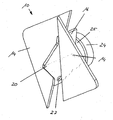
- FIG. 4 shows a perspective view of the drill bit 10 according to the invention.
- a cutting helix is formed by two cutting helix plates 14 which are welded on opposite sides of a center plate 16.
- the two cutting helical plates 14 form an angle 30, which is preferably about 20 °.
- the essential difference from the example shown in FIG. 1 is that in the variant shown in FIGS. 2 to 4 for stabilizing the drill bit 10, a pipe main body 24 is provided.
- the tube main body 24 consists essentially of a short tubular steel piece.
- the outer diameter 32 of the cutting helix 12 formed by the cutting helical plates 14 is, as shown in FIG. 3, about three times the outer diameter 34 of the pipe base body 24.
- the cutting helical plates 14 are welded on opposite sides of a center plate 16.
- This center plate 16 is received in slots 26 of the pipe base body 24 and thus rotatably connected to the pipe base body 24.
- a further significant improvement of the embodiment according to FIGS. 2 to 4 in comparison to FIG. 1 is that the center plate 16 is provided with two folds 18 transversely to its longitudinal edges.
- a tip 20, which may also be referred to as a centering tip is formed between these folds 18 .
- a significant increase in stability is achieved in a simple manner.
- the cutting helical plates 14 substantially in the form of equilateral right triangles.
- the two cutting helical plates 14 can be produced from a square steel plate.
- the cutting helical plates 14 are also supported in each case on helically rising stop regions 28, which are formed on the tube body 24. By means of these helically rising abutment regions 28 excellent stability and thus particularly long service life are made possible.
- FIGS. 5 and 6 An example of an open tube main body 24 for a drill bit according to the invention is shown schematically in FIGS. 5 and 6.
- the tube body 24 consists essentially of a pipe section 25, which on one side with the above described helical abutment portions 28 for supporting the cutting helical plates 14 and also provided with two oppositely arranged slots 26, which serve to receive the center plate 16.
- the pipe section 25 is also provided with a total of three openings 38, which can serve for the rotationally fixed connection of the pipe base body 24 with a drill pipe.
- suitable bolts can be inserted into the openings 38 for this purpose.
- the invention provides a new drill bit for an auger, which is of particularly simple construction and can be produced very cost-effectively with a minimum of material and production costs and thus overall.
- the drill bit according to the invention is therefore particularly well suited for applications in which the drill bit remains in the well after insertion of the hole.
Landscapes
- Engineering & Computer Science (AREA)
- Life Sciences & Earth Sciences (AREA)
- Geology (AREA)
- Mining & Mineral Resources (AREA)
- Mechanical Engineering (AREA)
- Physics & Mathematics (AREA)
- Environmental & Geological Engineering (AREA)
- Fluid Mechanics (AREA)
- General Life Sciences & Earth Sciences (AREA)
- Geochemistry & Mineralogy (AREA)
- Earth Drilling (AREA)
Claims (10)
- Pointe de forage pour une foreuse de sols avec une vis tranchante (12),
qui est formée par au moins deux plaques (14) de vis tranchante sensiblement triangulaires,
caractérisée en ce que, pour le montage sur un tube de forage, il est prévu un corps de base tubulaire (24),
en ce que la plaque centrale (16) est montée sur le corps de base tubulaire (24) d'une manière solidaire en rotation, et
en ce que lesdites au moins deux plaques (14) de vis tranchante sensiblement triangulaires sont placées sur la plaque centrale (16) de manière basculée l'une par rapport à l'autre. - Pointe de forage selon la revendication 1, caractérisée en ce que les plaques (14) de vis tranchante sont soudées sur la plaque centrale (16).
- Pointe de forage selon la revendication 2, caractérisée en ce que la plaque centrale (16) est munie d'un profil, en particulier un chanfrein (18).
- Pointe de forage selon l'une quelconque des revendications 2 ou 3, caractérisée en ce que la plaque centrale (16) présente une pointe (20) en saillie axiale.
- Pointe de forage selon la revendication 1, caractérisée en ce que le corps de base tubulaire (24) est muni de fentes latérales (26) pour recevoir et fixer la plaque centrale (16).
- Pointe de forage selon l'une quelconque des revendications 1 à 5, caractérisée en ce qu'une face frontale du corps de base tubulaire (24) est réalisée avec des zones d'appui (28) en forme de vis pour soutenir les plaques (14) de vis tranchante.
- Pointe de forage selon l'une quelconque des revendications 1 à 6, caractérisée en ce que deux plaques (14) de vis tranchante sont fabriquées à chaque fois à partir d'une plaque sensiblement carrée
- Pointe de forage selon l'une quelconque des revendications 1 à 7, caractérisée en ce que les plaques (14) de vis tranchante sont placées l'une par rapport à l'autre selon un angle (30) de 10° à 30°, de préférence de 15° à 25°.
- Pointe de forage selon l'une quelconque des revendications 1, 5 à 8, caractérisée en ce que le diamètre extérieur (32) de la vis tranchante (12) formée par les plaques de vis tranchante (14) est égal à approximativement 2,5 à 3,5 fois, de préférence 2,8 à 3,2 fois, le diamètre extérieur (34) du corps de base tubulaire (24).
- Foreuse de sols, caractérisée en ce qu'une pointe de forage (10) selon l'une des revendications 1 à 9 est prévue.
Priority Applications (2)
| Application Number | Priority Date | Filing Date | Title |
|---|---|---|---|
| DE502004003756T DE502004003756D1 (de) | 2004-03-26 | 2004-03-26 | Bohrspitze |
| EP04007476A EP1580397B1 (fr) | 2004-03-26 | 2004-03-26 | Trépan de forage |
Applications Claiming Priority (1)
| Application Number | Priority Date | Filing Date | Title |
|---|---|---|---|
| EP04007476A EP1580397B1 (fr) | 2004-03-26 | 2004-03-26 | Trépan de forage |
Publications (2)
| Publication Number | Publication Date |
|---|---|
| EP1580397A1 EP1580397A1 (fr) | 2005-09-28 |
| EP1580397B1 true EP1580397B1 (fr) | 2007-05-09 |
Family
ID=34854646
Family Applications (1)
| Application Number | Title | Priority Date | Filing Date |
|---|---|---|---|
| EP04007476A Expired - Lifetime EP1580397B1 (fr) | 2004-03-26 | 2004-03-26 | Trépan de forage |
Country Status (2)
| Country | Link |
|---|---|
| EP (1) | EP1580397B1 (fr) |
| DE (1) | DE502004003756D1 (fr) |
Families Citing this family (5)
| Publication number | Priority date | Publication date | Assignee | Title |
|---|---|---|---|---|
| PT1860274E (pt) | 2006-04-26 | 2008-07-31 | Bauer Maschinen Gmbh | Cabeça de perfuração |
| LT3216974T (lt) * | 2016-03-10 | 2019-03-12 | Marti Gründungstechnik Ag | Gręžimo įrenginio gręžimo galvutė gręžiniams mažo stabilumo grunte formuoti |
| US10337253B2 (en) | 2017-06-22 | 2019-07-02 | Marti Gründungstechnik Ag | Drill head for a drilling device for creating drill holes in insufficiently stable foundation |
| NO347081B1 (en) * | 2021-11-30 | 2023-05-08 | Braaten Helge Runar | Improved earth auger |
| EP4227467A1 (fr) * | 2022-02-09 | 2023-08-16 | Marti Gründungstechnik AG | Mèche de forage pour un dispositif de forage permettant de créer des trous de forage dans un terrain de fondation |
Family Cites Families (5)
| Publication number | Priority date | Publication date | Assignee | Title |
|---|---|---|---|---|
| US3198266A (en) * | 1963-07-02 | 1965-08-03 | Max L Mishler | Ice fishing drill |
| US3786876A (en) * | 1971-06-24 | 1974-01-22 | A Aaltonen | Ice auger |
| US4252202A (en) * | 1979-08-06 | 1981-02-24 | Purser Sr James A | Drill bit |
| US6227317B1 (en) * | 1997-07-09 | 2001-05-08 | Robert P. Severns | Garden auger having wings and cutters |
| US6502649B1 (en) * | 2000-10-16 | 2003-01-07 | Strikemaster Corporation | Ice auger cutting head |
-
2004
- 2004-03-26 EP EP04007476A patent/EP1580397B1/fr not_active Expired - Lifetime
- 2004-03-26 DE DE502004003756T patent/DE502004003756D1/de not_active Expired - Fee Related
Also Published As
| Publication number | Publication date |
|---|---|
| DE502004003756D1 (de) | 2007-06-21 |
| EP1580397A1 (fr) | 2005-09-28 |
Similar Documents
| Publication | Publication Date | Title |
|---|---|---|
| DE69705587T2 (de) | Mehrstufenbohrer und Anschlagvorrichtung für dengleichen | |
| DE69322096T2 (de) | Verbindung von kupplung mit schlauch | |
| EP0778100B1 (fr) | Foret héliocoidal de percussion | |
| EP2117752B1 (fr) | Dispositif de forage de roche | |
| EP0707129B1 (fr) | Outil de forage avec support et éléments de coupe | |
| EP0543960B1 (fr) | Element de fixation a rivet | |
| DE69816857T2 (de) | Fräswerkzeug zur verwendung in einem bohrloch und fräsverfahren | |
| EP2771143B1 (fr) | Mèche et procédé de fabrication d'une mèche | |
| EP1083294B1 (fr) | Outil de forage | |
| DE102019118338A1 (de) | Drehmoment-Antriebskopf | |
| EP0653544B1 (fr) | Foret hélicoidal | |
| EP1580397B1 (fr) | Trépan de forage | |
| EP0706870B1 (fr) | Scie tubulaire | |
| EP1083295B1 (fr) | Outil de forage | |
| EP1860274B1 (fr) | Pointe de forage | |
| EP1431511B1 (fr) | Foret à roche | |
| EP0778390B1 (fr) | Perceuse rotative hélicoidale à percussion | |
| DE2812195A1 (de) | Fraeserbefestigung an einem erdbohrer fuer bohrloecher grossen durchmessers | |
| EP4086426B1 (fr) | Accouplement de tiges d'une tige de tarière | |
| DE102013109796A1 (de) | Bohrer | |
| EP3289162B1 (fr) | Foret à glace | |
| EP0795677A2 (fr) | Outil de forage | |
| EP3647531A1 (fr) | Accouplement de tiges d'une tige de tarière | |
| DE102005011120B4 (de) | Schneckenbohrer | |
| EP1156183A1 (fr) | Tube de forage à double paroi |
Legal Events
| Date | Code | Title | Description |
|---|---|---|---|
| GRAP | Despatch of communication of intention to grant a patent |
Free format text: ORIGINAL CODE: EPIDOSNIGR1 |
|
| PUAI | Public reference made under article 153(3) epc to a published international application that has entered the european phase |
Free format text: ORIGINAL CODE: 0009012 |
|
| 17P | Request for examination filed |
Effective date: 20040915 |
|
| AK | Designated contracting states |
Kind code of ref document: A1 Designated state(s): AT BE BG CH CY CZ DE DK EE ES FI FR GB GR HU IE IT LI LU MC NL PL PT RO SE SI SK TR |
|
| AX | Request for extension of the european patent |
Extension state: AL LT LV MK |
|
| GRAS | Grant fee paid |
Free format text: ORIGINAL CODE: EPIDOSNIGR3 |
|
| AKX | Designation fees paid |
Designated state(s): DE GB IT |
|
| GRAA | (expected) grant |
Free format text: ORIGINAL CODE: 0009210 |
|
| AK | Designated contracting states |
Kind code of ref document: B1 Designated state(s): DE GB IT |
|
| REG | Reference to a national code |
Ref country code: GB Ref legal event code: FG4D Free format text: NOT ENGLISH |
|
| REF | Corresponds to: |
Ref document number: 502004003756 Country of ref document: DE Date of ref document: 20070621 Kind code of ref document: P |
|
| GBT | Gb: translation of ep patent filed (gb section 77(6)(a)/1977) |
Effective date: 20070612 |
|
| PLBE | No opposition filed within time limit |
Free format text: ORIGINAL CODE: 0009261 |
|
| STAA | Information on the status of an ep patent application or granted ep patent |
Free format text: STATUS: NO OPPOSITION FILED WITHIN TIME LIMIT |
|
| 26N | No opposition filed |
Effective date: 20080212 |
|
| PGFP | Annual fee paid to national office [announced via postgrant information from national office to epo] |
Ref country code: GB Payment date: 20080328 Year of fee payment: 5 |
|
| PGFP | Annual fee paid to national office [announced via postgrant information from national office to epo] |
Ref country code: DE Payment date: 20080328 Year of fee payment: 5 |
|
| PGFP | Annual fee paid to national office [announced via postgrant information from national office to epo] |
Ref country code: IT Payment date: 20080328 Year of fee payment: 5 |
|
| GBPC | Gb: european patent ceased through non-payment of renewal fee |
Effective date: 20090326 |
|
| PG25 | Lapsed in a contracting state [announced via postgrant information from national office to epo] |
Ref country code: DE Free format text: LAPSE BECAUSE OF NON-PAYMENT OF DUE FEES Effective date: 20091001 |
|
| PG25 | Lapsed in a contracting state [announced via postgrant information from national office to epo] |
Ref country code: GB Free format text: LAPSE BECAUSE OF NON-PAYMENT OF DUE FEES Effective date: 20090326 |
|
| PG25 | Lapsed in a contracting state [announced via postgrant information from national office to epo] |
Ref country code: IT Free format text: LAPSE BECAUSE OF NON-PAYMENT OF DUE FEES Effective date: 20090326 |