EP1580353A2 - Actuation device for a motor vehicle lock - Google Patents
Actuation device for a motor vehicle lock Download PDFInfo
- Publication number
- EP1580353A2 EP1580353A2 EP04029941A EP04029941A EP1580353A2 EP 1580353 A2 EP1580353 A2 EP 1580353A2 EP 04029941 A EP04029941 A EP 04029941A EP 04029941 A EP04029941 A EP 04029941A EP 1580353 A2 EP1580353 A2 EP 1580353A2
- Authority
- EP
- European Patent Office
- Prior art keywords
- actuating device
- handle
- protective cover
- axis
- securing element
- Prior art date
- Legal status (The legal status is an assumption and is not a legal conclusion. Google has not performed a legal analysis and makes no representation as to the accuracy of the status listed.)
- Withdrawn
Links
Images


Classifications
-
- E—FIXED CONSTRUCTIONS
- E05—LOCKS; KEYS; WINDOW OR DOOR FITTINGS; SAFES
- E05B—LOCKS; ACCESSORIES THEREFOR; HANDCUFFS
- E05B77/00—Vehicle locks characterised by special functions or purposes
- E05B77/02—Vehicle locks characterised by special functions or purposes for accident situations
-
- E—FIXED CONSTRUCTIONS
- E05—LOCKS; KEYS; WINDOW OR DOOR FITTINGS; SAFES
- E05B—LOCKS; ACCESSORIES THEREFOR; HANDCUFFS
- E05B85/00—Details of vehicle locks not provided for in groups E05B77/00 - E05B83/00
- E05B85/10—Handles
- E05B85/14—Handles pivoted about an axis parallel to the wing
- E05B85/18—Handles pivoted about an axis parallel to the wing a longitudinal grip part being pivoted about an axis parallel to the longitudinal axis of the grip part
-
- Y—GENERAL TAGGING OF NEW TECHNOLOGICAL DEVELOPMENTS; GENERAL TAGGING OF CROSS-SECTIONAL TECHNOLOGIES SPANNING OVER SEVERAL SECTIONS OF THE IPC; TECHNICAL SUBJECTS COVERED BY FORMER USPC CROSS-REFERENCE ART COLLECTIONS [XRACs] AND DIGESTS
- Y10—TECHNICAL SUBJECTS COVERED BY FORMER USPC
- Y10S—TECHNICAL SUBJECTS COVERED BY FORMER USPC CROSS-REFERENCE ART COLLECTIONS [XRACs] AND DIGESTS
- Y10S292/00—Closure fasteners
- Y10S292/31—Lever operator, flush
-
- Y—GENERAL TAGGING OF NEW TECHNOLOGICAL DEVELOPMENTS; GENERAL TAGGING OF CROSS-SECTIONAL TECHNOLOGIES SPANNING OVER SEVERAL SECTIONS OF THE IPC; TECHNICAL SUBJECTS COVERED BY FORMER USPC CROSS-REFERENCE ART COLLECTIONS [XRACs] AND DIGESTS
- Y10—TECHNICAL SUBJECTS COVERED BY FORMER USPC
- Y10S—TECHNICAL SUBJECTS COVERED BY FORMER USPC CROSS-REFERENCE ART COLLECTIONS [XRACs] AND DIGESTS
- Y10S292/00—Closure fasteners
- Y10S292/53—Mounting and attachment
-
- Y—GENERAL TAGGING OF NEW TECHNOLOGICAL DEVELOPMENTS; GENERAL TAGGING OF CROSS-SECTIONAL TECHNOLOGIES SPANNING OVER SEVERAL SECTIONS OF THE IPC; TECHNICAL SUBJECTS COVERED BY FORMER USPC CROSS-REFERENCE ART COLLECTIONS [XRACs] AND DIGESTS
- Y10—TECHNICAL SUBJECTS COVERED BY FORMER USPC
- Y10T—TECHNICAL SUBJECTS COVERED BY FORMER US CLASSIFICATION
- Y10T292/00—Closure fasteners
- Y10T292/57—Operators with knobs or handles
-
- Y—GENERAL TAGGING OF NEW TECHNOLOGICAL DEVELOPMENTS; GENERAL TAGGING OF CROSS-SECTIONAL TECHNOLOGIES SPANNING OVER SEVERAL SECTIONS OF THE IPC; TECHNICAL SUBJECTS COVERED BY FORMER USPC CROSS-REFERENCE ART COLLECTIONS [XRACs] AND DIGESTS
- Y10—TECHNICAL SUBJECTS COVERED BY FORMER USPC
- Y10T—TECHNICAL SUBJECTS COVERED BY FORMER US CLASSIFICATION
- Y10T292/00—Closure fasteners
- Y10T292/85—Knob-attaching devices
- Y10T292/865—Sliding
-
- Y—GENERAL TAGGING OF NEW TECHNOLOGICAL DEVELOPMENTS; GENERAL TAGGING OF CROSS-SECTIONAL TECHNOLOGIES SPANNING OVER SEVERAL SECTIONS OF THE IPC; TECHNICAL SUBJECTS COVERED BY FORMER USPC CROSS-REFERENCE ART COLLECTIONS [XRACs] AND DIGESTS
- Y10—TECHNICAL SUBJECTS COVERED BY FORMER USPC
- Y10T—TECHNICAL SUBJECTS COVERED BY FORMER US CLASSIFICATION
- Y10T70/00—Locks
- Y10T70/50—Special application
- Y10T70/5611—For control and machine elements
- Y10T70/5757—Handle, handwheel or knob
- Y10T70/5761—Retractable or flush handle
-
- Y—GENERAL TAGGING OF NEW TECHNOLOGICAL DEVELOPMENTS; GENERAL TAGGING OF CROSS-SECTIONAL TECHNOLOGIES SPANNING OVER SEVERAL SECTIONS OF THE IPC; TECHNICAL SUBJECTS COVERED BY FORMER USPC CROSS-REFERENCE ART COLLECTIONS [XRACs] AND DIGESTS
- Y10—TECHNICAL SUBJECTS COVERED BY FORMER USPC
- Y10T—TECHNICAL SUBJECTS COVERED BY FORMER US CLASSIFICATION
- Y10T70/00—Locks
- Y10T70/50—Special application
- Y10T70/5611—For control and machine elements
- Y10T70/5757—Handle, handwheel or knob
- Y10T70/5765—Rotary or swinging
- Y10T70/577—Locked stationary
Definitions
- the invention is based on an actuating device for a Motor vehicle door lock, according to the preamble of claim 1.
- From US-A-5 961 165 is a generic type actuating device for a Motor vehicle door lock, in which the motor vehicle door forms a tailgate.
- This actuator comprises a handle plate which is integral with the outer skin of the door can be connected.
- At the back of the handle plate is at least one bearing block provided in which via a thru axle at least one bearing arm of a handle is hinged pivotally. The bearing arm passes through the handle plate.
- the Actuator on a fuse element for the thru axle, which on the Thrust axle itself is formed by a deformed thru axle head.
- DE 198 09 449 A1 deals with an actuating device for a door lock, having a handle plate, at the rear of an insertion slot is arranged.
- One Handle passes through the handle plate and is pivotable about a in a bearing block Thrust axle stored.
- the bearing block, the handle and the bearing block taken thru axle are as a prefabricated unit in the slot pushed. Through the walls of the insertion slot, the thru-axle is against Slipped out.
- the object of the invention is an actuator of the type mentioned in which the assembly is simplified and in addition an optimized Has functional reliability.
- the advantages achieved by the invention are to be seen in that with the Attaching the protective cover on the back of the thru axle against slipping out is secured, so specially machined thru axles with an extended head or Like. Not necessarily needed.
- the Protective cover additionally a safety function, as for example in a Vehicle collision objects inside the vehicle door from the back the grip plate are kept away, whereby the reliability of the Actuator is optimized.
- a can break in the vehicle door arranged disc is caused by the Protective cover prevents glass parts from blocking the, in particular mechanical, door lock actuator.
- the Actuator used as outside door handle operation.
- the thru-axle is in two directions secured against slipping out of the bearing block.
- a variant is preferred in which the roof-shaped design of the fuse element penetration of foreign bodies in the Range of thru axle prevented.
- the risk of Penetration of a foreign body is reduced because the passage opening for the door lock - Actuator is introduced in the approximately vertically extending tray bottom.
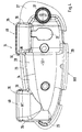
- actuating device 1 for a not shown here Door lock shown a motor vehicle door, of which in the following only as a door designated motor vehicle door in Fig. 2, a door outer panel 2 is shown. Im shown Embodiment is therefore assumed that the actuator used as an outside door operator. Also conceivable would be the use as a door inner actuator.
- the actuating device 1 has a handle plate 3, which in the outer door panel 2 is used.
- the grip plate 3 comprises an approximately flat plate portion 4 with a circumferential edge 5, wherein introduced into the plate portion 4, a cylinder opening 6 is, in which a lock cylinder 7 is inserted.
- the peripheral edge 5 and the Plate section 4 delimit a recessed grip 8 of the grip plate 3, which recessed grip 8 - relative to the outer panel 2 - set back, so that between a handle. 9 the actuating device 1 and the recessed grip 8 for moving the handle 9 can be intervened.
- the handle 9 has one, but preferably two Bearing arms 10 and 11 (Fig.
- the bearing arms 10, 11 are with their one ends 14 and 15 via an outer, the recessed grip 8 arranged arranged grip portion 16 of the Handle 9 firmly connected or handle portion 16 and bearing arms 10, 11 are integrally formed.
- the respective other end of the bearing arms 10, 11 is a as Bolt executed thru-axle 17, the two-piece with axle sections 18, 19 can be executed, arranged in each case one on the back 20 of the handle plate 3 Bearing block 21 and 22 connected, so that the handle 9 for actuating the Door lock pivoted from a rest position ST in an operating position BT can be, whereby one in Fig. 2 to see and connected to the handle 9 Door lock actuator 23 is moved while unlocking the door lock.
- the back 20 of the handle plate 3 is assigned by far a protective cover 24, which can be attached to the handle plate 3 or possibly on the door and this back 20 and the bearing arms 10 and 11 at least partially, at least above the Bearing blocks 21 and 22 covers.
- the protective cover 24 is at the Grip plate 3 attached, so that the actuator 1 as a prefabricated module in the opening 25 of the outer skin 2 of the door can be used, the edge 5 of the Handle plate 3, if necessary, with the interposition of a seal 26 on the outer panel 2 lie comes.
- the protective cover 24 is at least partially cupped executed, so that a cover portion 27 of the flat plate portion 4 of Handle plate 3, a shell portion 28 of the recessed grip 8 and a rim portion 29 of the Rand 5 is assigned, which edge 5 to the recessed grip 8 and which edge portion 29 rotates about the shell portion 28.
- the protective cover 24 is further one with the first Cylinder opening 6 aligned second cylinder opening 31 for the lock cylinder 7 and a passage opening 32 for the door lock - inserted actuator 21, wherein the Through opening 32 may lie in the shell portion 28, in particular in one Shell bottom 33 of the shell portion 28. From the shell bottom 33 is a circumferential shell wall 34, which in the edge portion 29 and the cover portion 27 passes. The shell bottom 33 and the edge portion 29 extend at least partially approximately parallel to the door outer panel 2 and the between edge portion 29 and Shell bottom 33 lying shell wall 34 includes an angle thereto.
- the protective cover 24 has at least one securing element 35, which is a Slipping out of the thru axle 17 from the bearing block 21 and 22 and the bearing arm 10 or 11 prevented.
- the securing element 35 at least one of the Protective cover 24, in particular of the edge portion 29, outgoing extension 36 on, in addition to a free end 37 or 38 of the thru-axle 17, preferably with small distance AB, comes to rest.
- an extension 36 and 39 is provided, the thru axle 17 between them take and according to the length of the thru axle 17 between them a have adapted clear width WT.
- the extensions 36 and 39 surmount the Edge contour RK1 or RK2, since the bearing blocks 10 and / or 11 on the edge contour RK1 and RK2 also extend and thus at least a portion of the thru axle 17th outside the edge contour RK1 or RK2.
- the extensions 36 and 39 are over a Roof section 40 connected to each other, so that the securing element 35 is a one Gaube similar configuration. Through the pulled up close to the edge 5 Roof section 40 is an intrusion of objects or foreign bodies in the Housing 30 prevented in most cases.
- two securing elements 35 for the two Axle sections 18 and 19 are provided, which fuse elements 35 in are essentially identical.
- the protective cover 24 with the / the Securing elements 35 is for example in one piece, preferably as plastic Molded part, manufactured.
Landscapes
- Lock And Its Accessories (AREA)
Abstract
Description
Bei der Erfindung wird ausgegangen von einer Betätigungseinrichtung für ein
Kraftfahrzeug - Türschloss, gemäß Oberbegriff des Anspruchs 1.The invention is based on an actuating device for a
Motor vehicle door lock, according to the preamble of
Aus der US - A - 5 961 165 ist eine gattungsbildende Betätigungseinrichtung für ein Kraftfahrzeug - Türschloss bekannt, bei dem die Kraftfahrzeugtür eine Heckklappe bildet. Diese Betätigungseinrichtung umfasst eine Griffplatte, die mit der Außenhaut der Tür verbunden werden kann. An der Rückseite der Griffplatte ist zumindest ein Lagerblock vorgesehen, in dem über eine Steckachse zumindest ein Lagerarm eines Handgriffs schwenkbar angelenkt ist. Der Lagerarm durchsetzt die Griffplatte. Ferner weist die Betätigungseinrichtung ein Sicherungselement für die Steckachse auf, das an der Steckachse selbst durch einen verformten Steckachsenkopf gebildet ist.From US-A-5 961 165 is a generic type actuating device for a Motor vehicle door lock, in which the motor vehicle door forms a tailgate. This actuator comprises a handle plate which is integral with the outer skin of the door can be connected. At the back of the handle plate is at least one bearing block provided in which via a thru axle at least one bearing arm of a handle is hinged pivotally. The bearing arm passes through the handle plate. Furthermore, the Actuator on a fuse element for the thru axle, which on the Thrust axle itself is formed by a deformed thru axle head.
Aus der DE 37 32 674 A1 ist eine Betätigungseinrichtung für ein Türschloss bekannt, beim der ein Handgriff an der Rückseite einer Griffplatte gelagert ist. Hierfür ist eine Steckachse vorgesehen, die eine Kerbe auf ihrer Mantelfläche aufweist, in die eine elastisch ausgeführte Klaue eingreift, die von der Griffplatte ausgeht.From DE 37 32 674 A1 an actuator for a door lock is known, when a handle is mounted on the back of a handle plate. For this is one Thrust axle provided, which has a notch on its lateral surface, in the one elastically executed claw engages, which emanates from the handle plate.
Die DE 198 09 449 A1 befasst sich mit einer Betätigungseinrichtung für ein Türschloss, die eine Griffplatte aufweist, an deren Rückseite ein Einschubschacht angeordnet ist. Ein Handgriff durchgreift die Griffplatte und ist in einem Lagerbock schwenkbar um eine Steckachse gelagert. Der Lagerbock, der Handgriff und die im Lagerbock aufgenommene Steckachse werden als vorgefertigte Einheit in den Einschubschacht geschoben. Durch die Wände des Einschubschachts wird die Steckachse gegen Herausrutschen gesichert.DE 198 09 449 A1 deals with an actuating device for a door lock, having a handle plate, at the rear of an insertion slot is arranged. One Handle passes through the handle plate and is pivotable about a in a bearing block Thrust axle stored. The bearing block, the handle and the bearing block taken thru axle are as a prefabricated unit in the slot pushed. Through the walls of the insertion slot, the thru-axle is against Slipped out.
Aufgabe der Erfindung ist es, eine Betätigungseinrichtung der eingangs genannten Art anzugeben, bei der die Montage vereinfacht ist und die darüber hinaus eine optimierte Funktionssicherheit aufweist. The object of the invention is an actuator of the type mentioned in which the assembly is simplified and in addition an optimized Has functional reliability.
Gelöst wird die Aufgabe mit einer Betätigungseinrichtung für ein Türschloss eines
Kraftfahrzeugs, die die in Anspruch 1 angeführten Merkmale aufweist. Weitere
Ausgestaltungen sind in den Unteransprüchen angegeben.The problem is solved with an actuator for a door lock of a
Motor vehicle having the features cited in
Die mit der Erfindung hauptsächlich erzielten Vorteile sind darin zu sehen, dass mit dem Anbringen der Schutzabdeckung an der Rückseite die Steckachse gegen Herausrutschen gesichert wird, also besonders bearbeitete Steckachsen mit einem erweiterten Kopf oder dgl. nicht zwingend benötigt werden. Neben der Sicherung der Steckachse erfüllt die Schutzabdeckung zusätzlich eine Sicherheitsfunktion, da beispielsweise bei einer Fahrzeugkollision sich innerhalb der Fahrzeugtür lösende Gegenstände von der Rückseite der Griffplatte ferngehalten werden, wodurch die Funktionssicherheit der Betätigungseinrichtung optimiert wird. Da beispielsweise bei einer Fahrzeugkollision eine in der Fahrzeugtür angeordnete Scheibe zerbrechen kann, wird durch die Schutzabdeckung verhindert, dass Glasteile zu einem Blockieren des, insbesondere mechanischen, Türschloss - Betätigers führen. Vorzugsweise wird die Betätigungseinrichtung als Türaußengriffbetätigung verwendet.The advantages achieved by the invention are to be seen in that with the Attaching the protective cover on the back of the thru axle against slipping out is secured, so specially machined thru axles with an extended head or Like. Not necessarily needed. In addition to securing the thru axle meets the Protective cover additionally a safety function, as for example in a Vehicle collision objects inside the vehicle door from the back the grip plate are kept away, whereby the reliability of the Actuator is optimized. For example, in a vehicle collision a can break in the vehicle door arranged disc is caused by the Protective cover prevents glass parts from blocking the, in particular mechanical, door lock actuator. Preferably, the Actuator used as outside door handle operation.
Nach einer Weiterbildung mit den in Anspruch 3 genannten Merkmalen wird das
Anbringen der Schutzabdeckung erleichtert.After a development with the features mentioned in
Bei einem Ausführungsbeispiel nach Anspruch 5 wird die Steckachse in zwei Richtungen
gegen Herausrutschen aus dem Lagerblock gesichert.In an embodiment according to
Entsprechend Anspruch 9 wird eine Ausführungsvariante bevorzugt, bei der die
dachförmige Ausbildung des Sicherungselements ein Eindringen von Fremdkörpern im
Bereich der Steckachse verhindert. According to
Gemäß einem in Anspruch 13 angegebenen Ausführungsbeispiel wird die Gefahr eines
Eindringens eines Fremdkörpers vermindert, da die Durchgriffsöffnung für den Türschloss
- Betätiger in dem etwa vertikal verlaufenden Schalenboden eingebracht ist.According to an embodiment specified in
Die Erfindung wird nachfolgend anhand eines Ausführungsbeispiels mit Bezug auf die Zeichnung näher erläutert. Es zeigen:
- Fig. 1
- eine Draufsicht auf eine Betätigungseinrichtung für ein Kraftfahrzeug - Türschloss,
- Fig. 2 und 3
- jeweils einen Schnitt durch die Betätigungseinrichtung nach Fig. 1 entlang der Linien II - II bzw. III - III.
- Fig. 4
- eine Draufsicht auf eine Schutzabdeckung für die Betätigungseinrichtung.
- Fig. 1
- a top view of an actuating device for a motor vehicle - door lock,
- FIGS. 2 and 3
- in each case a section through the actuating device according to FIG. 1 along the lines II-II or III-III.
- Fig. 4
- a plan view of a protective cover for the actuator.
Anhand der Fig. 1 bis 3 wird eine Betätigungseinrichtung 1 für ein hier nicht gezeigtes
Türschloss einer Kraftfahrzeugtür gezeigt, von welcher im folgenden lediglich als Tür
bezeichneten Kraftfahrzeugtür in Fig. 2 ein Türaußenblech 2 dargestellt ist. Im gezeigten
Ausführungsbeispiel wird demnach davon ausgegangen, dass die Betätigungseinrichtung
als Türaußenbetätigungseinrichtung verwendet ist. Denkbar wäre zudem die Verwendung
als Türinnenbetätigungseinrichtung.1 to 3 is an
Die Betätigungseinrichtung 1 weist eine Griffplatte 3 auf, die in das Türaußenblech 2
eingesetzt ist. Die Griffplatte 3 umfasst einen etwa ebenen Plattenabschnitt 4 mit einem
umlaufenden Rand 5, wobei in den Plattenabschnitt 4 eine Zylinderöffnung 6 eingebracht
ist, in die ein Schlosszylinder 7 eingesetzt ist. Der umlaufende Rand 5 und der
Plattenabschnitt 4 begrenzen eine Griffmulde 8 der Griffplatte 3, welche Griffmulde 8 -
bezogen auf das Außenblech 2 - zurückversetzt ist, so dass zwischen einem Handgriff 9
der Betätigungseinrichtung 1 und der Griffmulde 8 zum Bewegen des Handgriffs 9
eingegriffen werden kann. Der Handgriff 9 besitzt einen, vorzugsweise jedoch zwei
Lagerarme 10 bzw. 11 (Fig. 2 und 3), die die Griffplatte 3, insbesondere in der
Griffmulde 8, in Durchtrittsöffnungen 12 bzw. 13 von der Vorderseite VS der Griffplatte 3
her durchgreifen. Die Lagerarme 10, 11 sind mit ihren einen Enden 14 bzw. 15 über
einen außen liegenden, der Griffmulde 8 zugewandt angeordneten Griffabschnitt 16 des
Handgriffs 9 fest verbunden bzw. Griffabschnitt 16 und Lagerarme 10, 11 sind
einstückig ausgebildet. Das jeweils andere Ende der Lagerarme 10, 11 ist über eine als
Bolzen ausgeführte Steckachse 17, die zweiteilig mit Achsenabschnitten 18, 19
ausgeführt sein kann, in jeweils einem an der Rückseite 20 der Griffplatte 3 angeordneten
Lagerblock 21 bzw. 22 verbunden, so dass der Handgriff 9 zum Betätigen des
Türschlosses aus einer Ruhestellung ST in eine Betätigungsstellung BT verschwenkt
werden kann, wodurch ein in Fig. 2 zu sehender und an dem Handgriff 9 angebundener
Türschloss - Betätiger 23 bewegt wird und dabei das Türschloss entriegelt.The actuating
Der Rückseite 20 der Griffplatte 3 ist mit Abstand eine Schutzabdeckung 24 zugeordnet,
die an der Griffplatte 3 oder ggf. an der Tür befestigt sein kann und die diese Rückseite
20 und die Lagerarme 10 bzw. 11 zumindest teilweise, zumindest oberhalb der
Lagerblöcke 21 bzw. 22 abdeckt. Vorzugsweise ist die Schutzabdeckung 24 an der
Griffplatte 3 befestigt, so dass die Betätigungseinrichtung 1 als vorgefertigtes Modul in
die Öffnung 25 der Außenhaut 2 der Tür eingesetzt werden kann, wobei der Rand 5 der
Griffplatte 3 ggf. unter Zwischenschaltung einer Dichtung 26 auf dem Außenblech 2 zu
liegen kommt. Die Schutzabdeckung 24 ist zumindest abschnittweise schalenförmig
ausgeführt, so dass ein Abdeckungsabschnitt 27 dem ebenen Plattenabschnitt 4 der
Griffplatte 3, ein Schalenabschnitt 28 der Griffmulde 8 und ein Randabschnitt 29 dem
Rand 5 zugeordnet ist, welcher Rand 5 um die Griffmulde 8 und welcher Randabschnitt
29 um den Schalenabschnitt 28 umläuft. Es ergibt sich so eine Randkontur RK1 der
Schutzabdeckung 24, die der annähernd ovalen Randkontur RK2 der Griffplatte folgt, so
dass der Randabschnitt 29 und ggf. der Abdeckungsabschnitt 27 auf dem zugeordneten
Rand 5 und ggf. dem Plattenabschnitt 4 aufliegen können, wodurch sich ein im
wesentlichen geschlossenes Gehäuse 30 aus der Schutzabdeckung 24 und der
Griffplatte 3 ergibt. In die Schutzabdeckung 24 ist ferner eine mit der ersten
Zylinderöffnung 6 fluchtende zweite Zylinderöffnung 31 für den Schlosszylinder 7 und
eine Durchgriffsöffnung 32 für den Türschloss - Betätiger 21 eingebracht, wobei die
Durchgriffsöffnung 32 in dem Schalenabschnitt 28 liegen kann, insbesondere in einem
Schalenboden 33 des Schalenabschnitts 28. Von dem Schalenboden 33 geht eine
umlaufende Schalenwand 34 aus, die in den Randabschnitt 29 und den Abdeckabschnitt
27 übergeht. Der Schalenboden 33 und der Randabschnitt 29 verlaufen zumindest
teilweise etwa parallel zum Türaußenblech 2 und die zwischen Randabschnitt 29 und
Schalenboden 33 liegende Schalenwand 34 schließt einen Winkel dazu ein.The
Die Schutzabdeckung 24 weist zumindest ein Sicherungselement 35 auf, das ein
Herausrutschen der Steckachse 17 aus dem Lagerblock 21 bzw. 22 und dem Lagerarm
10 bzw. 11 verhindert. Dazu weist das Sicherungselement 35 wenigstens einen von der
Schutzabdeckung 24, insbesondere von deren Randabschnitt 29, ausgehenden Fortsatz
36 auf, der neben einem freien Ende 37 oder 38 der Steckachse 17, vorzugsweise mit
geringem Abstand AB, zu liegen kommt. Bevorzugt ist für jedes Ende 37 und 38 der
Steckachse 17 ein Fortsatz 36 und 39 vorgesehen, die zwischen sich die Steckachse 17
aufnehmen und entsprechend der Länge der Steckachse 17 zwischen sich eine daran
angepasste lichte Weite WT aufweisen. Die Fortsätze 36 und 39 überragen die
Randkontur RK1 bzw. RK2, da sich die Lagerblöcke 10 und/oder 11 über die Randkontur
RK1 bzw. RK2 hinaus erstrecken und somit zumindest ein Abschnitt der Steckachse 17
außerhalb der Randkontur RK1 bzw. RK2 liegt. Die Fortsätze 36 und 39 sind über einen
Dachabschnitt 40 miteinander verbunden, so dass das Sicherungselement 35 eine einer
Gaube ähnliche Ausgestaltung aufweist. Durch den bis nahe an den Rand 5 gezogenen
Dachabschnitt 40 wird ein Eindringen von Gegenständen bzw. Fremdkörpern in das
Gehäuse 30 in den meisten Fällen verhindert.The
Sofern - wie vorstehend erwähnt - eine zweiteilige Steckachse 17 mit den zwei
Achsenabschnitten 18 und 19 für die schwenkbare Lagerung des Handgriffs 8 an der
Griffplatte 3 verwendet wird, sind zwei Sicherungselemente 35 für die beiden
Achsenabschnitte 18 und 19 vorgesehen, welche Sicherungselemente 35 im
wesentlichen identisch ausgebildet sind. Die Schutzabdeckung 24 mit dem/den
Sicherungselementen 35 wird beispielsweise einstückig, vorzugsweise als Kunststoff -
Formteil, hergestellt.If - as mentioned above - a two-piece thru
Claims (13)
Applications Claiming Priority (2)
| Application Number | Priority Date | Filing Date | Title |
|---|---|---|---|
| DE200410015136 DE102004015136B3 (en) | 2004-03-27 | 2004-03-27 | Actuating device for a motor vehicle door lock |
| DE102004015136 | 2004-03-27 |
Publications (2)
| Publication Number | Publication Date |
|---|---|
| EP1580353A2 true EP1580353A2 (en) | 2005-09-28 |
| EP1580353A3 EP1580353A3 (en) | 2007-03-28 |
Family
ID=34854092
Family Applications (1)
| Application Number | Title | Priority Date | Filing Date |
|---|---|---|---|
| EP04029941A Withdrawn EP1580353A3 (en) | 2004-03-27 | 2004-12-17 | Actuation device for a motor vehicle lock |
Country Status (4)
| Country | Link |
|---|---|
| US (1) | US7237411B2 (en) |
| EP (1) | EP1580353A3 (en) |
| JP (1) | JP2005282351A (en) |
| DE (1) | DE102004015136B3 (en) |
Cited By (2)
| Publication number | Priority date | Publication date | Assignee | Title |
|---|---|---|---|---|
| DE102011018750A1 (en) | 2011-04-27 | 2012-10-31 | Audi Ag | The door handle assembly |
| CN104295167B (en) * | 2014-09-18 | 2016-11-16 | 无锡忻润汽车安全系统有限公司 | Car door is outer pin shaft connecting apparatus |
Families Citing this family (19)
| Publication number | Priority date | Publication date | Assignee | Title |
|---|---|---|---|---|
| DE102005022970B3 (en) * | 2005-05-19 | 2006-10-19 | Dr.Ing.H.C. F. Porsche Ag | Lock arrangement for a vehicle door comprises a shaft arranged between a door lock and a closing cylinder to interact with a rotating receiving element on the door lock |
| US20070028656A1 (en) * | 2005-08-04 | 2007-02-08 | Jospe Joseph L | Lockable pull handle |
| US7971460B2 (en) * | 2006-10-30 | 2011-07-05 | Zagoroff Dimiter S | Method and mechanism for attaching a locking mechanism to a pick-up truck tailgate |
| USD588895S1 (en) | 2007-01-26 | 2009-03-24 | Trimark Corporation | Inside door handle for motor vehicle |
| USD564855S1 (en) * | 2007-02-21 | 2008-03-25 | Trimark Corporation | Remote pull handle |
| JP4914763B2 (en) * | 2007-05-22 | 2012-04-11 | 株式会社アルファ | Handle device |
| USD630488S1 (en) * | 2008-03-10 | 2011-01-11 | Southco, Inc. | Paddle actuator |
| USD628041S1 (en) * | 2008-03-10 | 2010-11-30 | Southco, Inc. | Multi-point paddle actuator |
| USD628042S1 (en) * | 2008-03-10 | 2010-11-30 | Southco, Inc. | Lever actuator |
| USD619871S1 (en) * | 2008-10-28 | 2010-07-20 | D. la Porte Söhne GmbH | Vehicle door handle |
| JP5293087B2 (en) * | 2008-10-29 | 2013-09-18 | アイシン精機株式会社 | Vehicle door opening / closing operation device |
| DE102009056921A1 (en) * | 2009-12-03 | 2011-06-09 | GM Global Technology Operations LLC, ( n. d. Ges. d. Staates Delaware ), Detroit | Handle module for a motor vehicle door |
| US9181733B2 (en) * | 2010-01-28 | 2015-11-10 | Kabushiki Kaisha Honda Lock | Vehicle door handle system |
| US8925361B2 (en) * | 2010-02-02 | 2015-01-06 | GM Global Technology Operations LLC | Anti-theft device for an access door |
| US8720118B2 (en) * | 2012-04-10 | 2014-05-13 | Toyota Motor Engineering & Manufacturing North America, Inc. | Vehicle door trim panel |
| USD712232S1 (en) * | 2013-03-07 | 2014-09-02 | Paccar Inc | Door release |
| DE102013109914A1 (en) * | 2013-09-10 | 2015-03-12 | BROSE SCHLIEßSYSTEME GMBH & CO. KG | Cover flap arrangement for a handle arrangement of a motor vehicle door |
| USD818790S1 (en) * | 2016-05-25 | 2018-05-29 | International Truck Intellectual Property Company, Llc | Door handle for a truck vehicle |
| USD993860S1 (en) * | 2021-04-13 | 2023-08-01 | The Shyft Group, Inc. | Vehicle door handle escutcheon |
Citations (4)
| Publication number | Priority date | Publication date | Assignee | Title |
|---|---|---|---|---|
| DE3732674A1 (en) | 1986-09-30 | 1988-05-05 | Aisin Seiki | INTERNAL HANDLE FOR A MOTOR VEHICLE |
| JPH01162564U (en) | 1988-04-30 | 1989-11-13 | ||
| US5340174A (en) | 1993-04-12 | 1994-08-23 | Chrysler Corporation | Mounting arrangement for vehicle door handle |
| US5961165A (en) | 1995-09-27 | 1999-10-05 | Nissan Motor Co., Ltd. | Outer door handle structure for vehicular door |
Family Cites Families (12)
| Publication number | Priority date | Publication date | Assignee | Title |
|---|---|---|---|---|
| US529887A (en) * | 1894-11-27 | Knob attachment | ||
| JPS57174578A (en) * | 1981-04-21 | 1982-10-27 | Ohi Seisakusho Co Ltd | Handle apparatus of automobile door |
| FR2592909A1 (en) * | 1986-01-10 | 1987-07-17 | Renault | FLUSH HANDLE MOUNTING FOR VEHICLE DOOR. |
| LU87046A1 (en) | 1987-11-12 | 1989-06-14 | Wurth Paul Sa | DEVICE FOR ADJUSTING THE FLOW OF A FUSED MATERIAL AND APPLICATION TO A CONTINUOUS CASTING SYSTEM |
| JP3246126B2 (en) * | 1993-02-08 | 2002-01-15 | アイシン精機株式会社 | Outside handle structure for automobiles |
| JP4123553B2 (en) * | 1997-12-25 | 2008-07-23 | アイシン精機株式会社 | Door outside handle device |
| DE19809449B4 (en) * | 1998-03-05 | 2007-02-22 | Volkswagen Ag | Actuating device for a motor vehicle door lock |
| US6059329A (en) * | 1998-03-13 | 2000-05-09 | Adac Plastics Inc. | Door handle assembly with self-actuated mounting |
| JP4345128B2 (en) * | 1999-03-30 | 2009-10-14 | アイシン精機株式会社 | Vehicle door lock operating system and vehicle door equipped with the vehicle door lock operating system |
| DE19948677B4 (en) * | 1999-10-08 | 2006-11-09 | Audi Ag | Device for closing and opening a lockable ceiling part, in particular a vehicle cover part for a boot cover |
| US6349450B1 (en) * | 2000-06-20 | 2002-02-26 | Donnelly Corporation | Vehicle door handle |
| JP3569675B2 (en) * | 2000-12-14 | 2004-09-22 | 株式会社ユーシン | Automotive steering wheel device |
-
2004
- 2004-03-27 DE DE200410015136 patent/DE102004015136B3/en not_active Expired - Fee Related
- 2004-12-17 EP EP04029941A patent/EP1580353A3/en not_active Withdrawn
-
2005
- 2005-03-15 US US11/079,076 patent/US7237411B2/en not_active Expired - Fee Related
- 2005-03-25 JP JP2005089782A patent/JP2005282351A/en active Pending
Patent Citations (4)
| Publication number | Priority date | Publication date | Assignee | Title |
|---|---|---|---|---|
| DE3732674A1 (en) | 1986-09-30 | 1988-05-05 | Aisin Seiki | INTERNAL HANDLE FOR A MOTOR VEHICLE |
| JPH01162564U (en) | 1988-04-30 | 1989-11-13 | ||
| US5340174A (en) | 1993-04-12 | 1994-08-23 | Chrysler Corporation | Mounting arrangement for vehicle door handle |
| US5961165A (en) | 1995-09-27 | 1999-10-05 | Nissan Motor Co., Ltd. | Outer door handle structure for vehicular door |
Cited By (3)
| Publication number | Priority date | Publication date | Assignee | Title |
|---|---|---|---|---|
| DE102011018750A1 (en) | 2011-04-27 | 2012-10-31 | Audi Ag | The door handle assembly |
| EP2518244A3 (en) * | 2011-04-27 | 2017-06-28 | Audi AG | Door handle assembly |
| CN104295167B (en) * | 2014-09-18 | 2016-11-16 | 无锡忻润汽车安全系统有限公司 | Car door is outer pin shaft connecting apparatus |
Also Published As
| Publication number | Publication date |
|---|---|
| EP1580353A3 (en) | 2007-03-28 |
| DE102004015136B3 (en) | 2005-09-29 |
| US20050210936A1 (en) | 2005-09-29 |
| JP2005282351A (en) | 2005-10-13 |
| US7237411B2 (en) | 2007-07-03 |
Similar Documents
| Publication | Publication Date | Title |
|---|---|---|
| EP1580353A2 (en) | Actuation device for a motor vehicle lock | |
| DE10392815B4 (en) | Lock for a door of a motor vehicle | |
| EP2454428B1 (en) | Lock for a door or a tailgate on a motor vehicle | |
| EP3956185B1 (en) | Wind deflector for a windscreen wiper system of a motor vehicle | |
| DE19845723B4 (en) | Locking device for a vehicle door | |
| DE10247474A1 (en) | Lock member attaching device | |
| DE10144166C5 (en) | Lock for a motor vehicle door | |
| DE112015001176T5 (en) | Sturktur for a rear part of a vehicle | |
| EP3128108B1 (en) | Handle unit | |
| DE102024129354A1 (en) | Arrangement for providing a fastening option for a vehicle component | |
| DE102008006110B4 (en) | Locking device | |
| WO2008151949A1 (en) | Device for actuating the closure of a movable part | |
| DE19649743B4 (en) | Locking device for a cover with a lock bolt cover | |
| DE102017107055A1 (en) | Gleitverbindungsapplikation | |
| EP2668357B1 (en) | Handle for a motor vehicle | |
| DE102018113820A1 (en) | Motor vehicle lock | |
| DE19722503A1 (en) | Automotive hatch locking mechanism | |
| DE102006044953B4 (en) | Fastening device for fastening a door panel of a motor vehicle | |
| WO2020099961A1 (en) | Motor vehicle lock | |
| DE102006020044B4 (en) | Fixing a door handle | |
| DE102005032926A1 (en) | Lock system for vehicle trunk lid, especially for automobile, has protective cover arranged inside lock chamber to cover lock on front side facing inner cladding and on inner side facing away from lock part | |
| WO2019096499A1 (en) | Door handle arrangement of a motor vehicle | |
| EP2343221B1 (en) | Rollover protection for motor vehicles | |
| DE102005042288A1 (en) | Loading edge covering for use in motor vehicle rear area, has opening, and flap device that is movable from closing position into opening position and detachably fastened to lining part, where lining part is made from stainless steel | |
| EP1403454A1 (en) | Closing device for a vehicle door |
Legal Events
| Date | Code | Title | Description |
|---|---|---|---|
| PUAI | Public reference made under article 153(3) epc to a published international application that has entered the european phase |
Free format text: ORIGINAL CODE: 0009012 |
|
| AK | Designated contracting states |
Kind code of ref document: A2 Designated state(s): AT BE BG CH CY CZ DE DK EE ES FI FR GB GR HU IE IS IT LI LT LU MC NL PL PT RO SE SI SK TR |
|
| AX | Request for extension of the european patent |
Extension state: AL BA HR LV MK YU |
|
| PUAL | Search report despatched |
Free format text: ORIGINAL CODE: 0009013 |
|
| AK | Designated contracting states |
Kind code of ref document: A3 Designated state(s): AT BE BG CH CY CZ DE DK EE ES FI FR GB GR HU IE IS IT LI LT LU MC NL PL PT RO SE SI SK TR |
|
| AX | Request for extension of the european patent |
Extension state: AL BA HR LV MK YU |
|
| 17P | Request for examination filed |
Effective date: 20070928 |
|
| AKX | Designation fees paid |
Designated state(s): DE ES FR GB IT SE |
|
| RAP1 | Party data changed (applicant data changed or rights of an application transferred) |
Owner name: DR. ING. H.C. F. PORSCHE AKTIENGESELLSCHAFT |
|
| RAP1 | Party data changed (applicant data changed or rights of an application transferred) |
Owner name: DR. ING. H.C. F. PORSCHE AKTIENGESELLSCHAFT |
|
| RAP1 | Party data changed (applicant data changed or rights of an application transferred) |
Owner name: DR. ING. H.C. F. PORSCHE AG |
|
| 17Q | First examination report despatched |
Effective date: 20120704 |
|
| STAA | Information on the status of an ep patent application or granted ep patent |
Free format text: STATUS: THE APPLICATION IS DEEMED TO BE WITHDRAWN |
|
| 18D | Application deemed to be withdrawn |
Effective date: 20170103 |