EP1580133A2 - Method and apparatus for discharging bulk materials - Google Patents
Method and apparatus for discharging bulk materials Download PDFInfo
- Publication number
- EP1580133A2 EP1580133A2 EP04017777A EP04017777A EP1580133A2 EP 1580133 A2 EP1580133 A2 EP 1580133A2 EP 04017777 A EP04017777 A EP 04017777A EP 04017777 A EP04017777 A EP 04017777A EP 1580133 A2 EP1580133 A2 EP 1580133A2
- Authority
- EP
- European Patent Office
- Prior art keywords
- suction
- compressed air
- nozzles
- bulk material
- suction device
- Prior art date
- Legal status (The legal status is an assumption and is not a legal conclusion. Google has not performed a legal analysis and makes no representation as to the accuracy of the status listed.)
- Granted
Links
Images


Classifications
-
- B—PERFORMING OPERATIONS; TRANSPORTING
- B65—CONVEYING; PACKING; STORING; HANDLING THIN OR FILAMENTARY MATERIAL
- B65B—MACHINES, APPARATUS OR DEVICES FOR, OR METHODS OF, PACKAGING ARTICLES OR MATERIALS; UNPACKING
- B65B69/00—Unpacking of articles or materials, not otherwise provided for
- B65B69/0075—Emptying systems for flexible intermediate bulk containers [FIBC]
- B65B69/0091—Emptying systems for flexible intermediate bulk containers [FIBC] using frames whereby the container is bottom supported
-
- B—PERFORMING OPERATIONS; TRANSPORTING
- B65—CONVEYING; PACKING; STORING; HANDLING THIN OR FILAMENTARY MATERIAL
- B65G—TRANSPORT OR STORAGE DEVICES, e.g. CONVEYORS FOR LOADING OR TIPPING, SHOP CONVEYOR SYSTEMS OR PNEUMATIC TUBE CONVEYORS
- B65G53/00—Conveying materials in bulk through troughs, pipes or tubes by floating the materials or by flow of gas, liquid or foam
- B65G53/34—Details
- B65G53/40—Feeding or discharging devices
- B65G53/42—Nozzles
Definitions
- the invention relates to an apparatus and a method for emptying Bulk goods made of flexible, in particular bag or bag-like containers.
- Another delivery form are so-called octabins, so containers with one solid, octagonal peripheral wall in which the flexible inner container in shape a film bag, which is filled with granules, is arranged.
- Emptying devices usually consist of a gallows-shaped or portal-shaped base frame, under which the container is placed.
- Base frame is from above a suction device in the open top Introduced container, and by means of suction through a suction hose the Bulk goods transported to the desired location.
- suction device used in the simplest case, a suction tube, which, however, has only a small diameter at its front end and therefore over the comparatively large surface area of the container, which may be greater than 1 m 2 , in the transverse direction and also in the vertical of an operator must be tracked.
- the bag-like, flexible container is pulled up at the upper edge, whereby the flanks of the container are getting steeper, what else This can be favored by the fact that the support frame to which the upper edge the container is attached, has a smaller diameter than that flexible container in the filled state.
- the basic idea of the method according to the invention or the invention Device is that the bulk material whose particles partially are compressed and stick together and therefore depending on existing ones Boundary conditions no longer to the suction of the suction device slipping, be separated by applying more compressed air. Singling does not necessarily mean singling down to a single one Particles mean, but also smaller accumulations of particles from particles Their environment are usually already manageable.
- the bulk material in the vicinity of the suction device loosened by applying compressed air, so the particles from each other solved to facilitate their slippage in the direction of suction or even To promote, the latter by the direction of the compressed air introduction a downward directed component.
- z. B distributed over the circumference of the suction device and / or distributed over the height thereof, arranged.
- the Compressed air jets preferably with a small impact surface and thus with a pointed cone characteristic, that is as punctual, trained, and the Jet exits the nozzle at a pressure of 2-8 bar, especially 4-6 bar.
- the direction of the nozzles is preferably directed obliquely downwards, for example at an angle of 20-80 °, in particular of 30-60 °, in particular from 40 - 50 °.
- the suction can be promoted by the suction device itself or the substrate of the container brings vibrations into the granules and / or the suction device over again, preferably periodically and automatically raised, either raised only within the suction hole or raised above the top of the suction hole and then back to the bulk, so z.
- the bottom of the suction, lowered is, but preferably offset laterally to the original position.
- the goal is to spite the environment of the suction device the individual point effect of the individual compressed air jet area to edit as much as possible over the entire area of the suction hole Separating the particles and thus slipping the bulk material downwards to allow in the direction of the suction opening of the suction head.
- the effective area of the nozzles does not have to reach the suction opening itself, and the spheres of influence do not have to connect directly with each other, because with selective loosening also the areas between the individual Loosen loosening areas of stability and then likewise collapse.
- the area effect can be increased by different measures be it by circular jet direction of the compressed air nozzles or through mechanical devices, e.g. B. Guiding devices that change direction.
- this conical shape can also be achieved differently, for example by the nozzles arranged further above, despite the same radial distance to vertical center of the suction device, a larger radial impact area have as the underlying, and thereby by means of the adding Impact areas created a virtual conical influence frame becomes.
- the Suction is a simple suction tube with an opening at the free end, on arranged the outer periphery and preferably not radially projecting the Nozzles are arranged, for. B. spaced in two or three longitudinally Levels.
- the compressed air nozzles are preferably via a central compressed air line with Compressed air supplied and from an existing stationary compressed air network with Compressed air supplies.
- the central supply line is preferably at the Also flexible suction hose can be attached and fit together with this move.
- the compressed air nozzles and their Supply lines to an existing suction device in particular a suction head, retrofittable, for example by means of brackets or The top, outside or bottom of the suction head can be screwed on or otherwise attachable.
- the pressure of the compressed air network is for use on the compressed air nozzles reduced by means of an adjustable reducing valve.
- a Control preferably an electrical control
- the Negative pressure in the suction hose in turn opens directly Compressed air valve for the supply of compressed air nozzles, while the strength of the Manually reduce pressure by adjusting the pressure reducing valve is given.
- Pulsating beam and possibly also rotating beam can be predetermined solely by the structural design of the nozzle, wherein the In addition, nozzles may be mechanically manually adjustable, z. B. between permanent beam and pulsating beam, between stationary beam and rotating beam.
- an electrical control it is integrated into the usual existing electrical control, which the suction device, the lifting mechanism for the suction head and / or the lifting mechanism for controls the container.
- suction device in the container to horizontal move, z. B. to let circle.
- Suction device in their diameter very large and to design this Purpose preferably a plurality of suction openings distributed over the base either individually are so small that the total area of the Suction openings is smaller than the cross section of the central, promotional Suction hose or the individual suction openings periodically one after the other, but never all at the same time, be acted upon by the negative pressure.
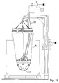
- FIGS. 1 a and b show the respective emptying device in FIG the side view, once with almost complete filling of the container. 6 with bulk material 13 and once with almost completely emptied container 6.
- the container 6 is one in an octabin 7, so with solid container walls, taken on a pallet under the superstructure of the Emptying device is.
- the emptying device in each case comprises a holding frame 1, the horizontal annularly centrally above the bag-shaped container. 6 is arranged and the upper edge of the container 6 by means of a holding element 21 in the form of a circumferential around the support frame 1 clamping belt holds.
- the support frame 1 is pulled by means of a cable 3 'up, over Deflection rollers 9 'along the transverse strut 19 and the vertical strut 20 along is and is connected to a container cylinder 24, with the help of the Holding frame 1 pulled up and thus - as shown in Fig. 1 b - the Side walls can be straightened.
- the holding frame 1 Since the holding frame 1 has a smaller diameter than the container 6 in filled state, the side walls of the bag-shaped container especially in the area above the bulk material 13 pulled inwards until - Towards the end of the emptying process - they rest on the suction head 4 outside.
- the suction head 4, from which the suction hose 16 leads upwards, is also by means of a cable 3, which is guided over analog deflection rollers 8, 9, too another lifting cylinder 14 out, which is the raising and lowering of the Suction head is used.
- Both cylinders 14, 24 are vertical to the vertical strut 20, in particular to their rear side facing away from the octabine 7, attached, and are about a Controlled 17, either on the vertical strut 20 or on a separate hanging cable is attached.
- controller 17 is e.g. set whether and how often the suction head 4 off the bulk material 13 is pulled out and lowered again on this, and / or how deep the suction head 4 after placement on the surface of the bulk material 13 may sink before lifting and pulling out of the Bulk material takes place, which is carried out several times in succession.
- the cable 3 at the end of the piston rod of Lifting cylinder 14 not directly attached, but at the end only one another role 26 out, and ends at a fixed point.
- the height of the vertical strut 20 or 20 is sufficient for attachment an approximately half as long cylinder 14 thereon, so if the other half of Height of the vertical strut 20 or 20 "available as a movement path of the roller stands.
- the suction head 4 in addition to Compressed air nozzles 33 is equipped, the compressed air jets 32 from the suction head 4 from directed radially outward against the bulk material 13, preferably obliquely directed downwards, against the walls of the suction hole 18, which is formed by the suction of bulk material 13 from above in the middle of the container.
- the goal here is, on the one hand, always plenty of enough, so not glued or otherwise solidified bulk material 13 in the area to bring the suction opening 4a of the suction head 4, and on the other hand, the emerging suction hole 18 as large as possible to make the remaining forming walls as far apart as possible on bulk material 13, what facilitates their collapse, what by pulling up the baggy 6 container and with the walls constantly pushing in or out time intervals is promoted.
- All compressed air nozzles 33 are connected via a central supply line 35, the is preferably guided along the suction hose 16 to the suction head 4, with Compressed air supplied.
- the suction nozzles 33 In the upper level are the suction nozzles 33 by means of brackets 34, always carry two or more nozzles 33, along the upper peripheral edge of the Suction head 4 attached, for example by the headband 34 on the top the suction head 4 are screwed, so that the nozzles 33 just above the Upper edge are positioned.
- nozzles 33 are in a second, deeper level along the Conical surface of the suction head arranged. It may be used in other, e.g. third even deeper level, nozzles 33 are arranged, which then still are positioned closer to the suction opening 4a.
- the nozzles 33 are each directed radially outward and obliquely downward, and preferably the more downward, the deeper and closer to the Suction opening 4a they are arranged on the suction head 4.
- the suction head 4 works like Described in the bulk material 13 down, wherein the suction hole 18th collapse surrounding walls of bulk material 13 or brought to collapse and slipping down until the quasi-completely empty state 1 b is achieved by the bag-like container 6 on the outer circumference the suction head 4 is applied and at most in the remaining distance between the underside of the suction head 4 and the container 6 extending there still Remains of bulk 13 are present in very small amount.
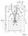
- FIG. 2 shows an emptying device, wherein the support frame 43 not only from a vertical strut 20 and an abstreben from above free cantilever cross member 19 is made, but portal-shaped with two distinguished Vertical struts 20 and one connecting them, mounted on both sides Cross strut 19 'exists.
- the suction head 4 ' is also designed differently, and consists essentially of a suction lance 39, so a piece of pipe whose open lower end the Suction port 4a represents, and at the upper end of the flexible suction hose 16 is connected.
- compressed air nozzles 33 which point obliquely outwards at the bottom Surface, in this case the downward conical surface of the weight body 25 of the suction head 4 '- this time only in a single vertical plane circumferential - arranged.
- the nozzles 33 may be via lines or Holes in the interior of the weight body 25 with that of the supply line 35 supplied compressed air are supplied.
- FIG. 2 Another special feature is in Figure 2 due to a small upper opening of the container 6 'an air supply line 26 from outside the container 6' to Suction head 4 'out, which provides supply air near the suction opening 4a, to avoid that the suction process is interrupted because of a defect on inflowing air.
- a weight is still a special one Fixed outer contour forming body, but in two superimposed arranged levels are on the suction lance 39 in each plane above the Scope distributed several suction nozzles 33 arranged on the suction lance 39, and although from bottom to top with increasing radial, horizontal distance from 3 vertical suction lance 39th
- the nozzles 33 are from the lower end, that is Suction opening 4a, offset upwards circulating directly on the outer circumference of the Suction lance 39 arranged.
- the nozzles 33 are spaced radially outward, in FIG vertical direction approximately at the height of the transition between suction lance 39 and flexible suction hose 16, arranged, for example, again by means of in Figure 1 mentioned retaining bracket 34 which on a suction lance 39 surrounding Ring or circular plate can be attached and therefore - as in the solution can be retrofitted to a conventional suction head 4, 4 'according to Figure 1 or 2.
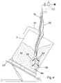
- FIG. 4 clearly shows that such a cone-shaped Suction hole 18 is not formed when, as shown in Figure 4 in several levels at e.g. the suction lance 39 superposed nozzles 33 each have the same have lateral radial distance to the central axis and thus the suction lance 39, by directly on the outer circumference of the suction lance 39 as in FIG are arranged.
- FIG. 4 differs from that of FIG Figures 1 to 3, characterized in that in Figure 4 of a suction lance 39 existing Suction head, as shown in Figures 1 to 3 with a flexible suction hose in Connection stands and its compressed air nozzles 33 by means of a compressed air supply line 35 are supplied, even at a liftable Hoist is attached, still the container is attached to a hoist, which in the present case of an octabin 7 with fixed peripheral walls consists.
- the octabin 7 stands on a base plate 23 ', which by means of e.g. Hydraulic cylinder can be tilted obliquely, so that one of the lower edges of the Octabins 7 represents its lowest point at the end of the Fill state collect the remains of bulk material 13. The inclination is only after partial emptying of octabin 7 performed.
- suction lance 39 in the absence of a hoist At least somewhat in position to fix, is at the suction lance 39 and / or the suction hose 16 above a suspension device 41, e.g. in the form of a Ein vonbügels, arranged by means of which the suction lance the top of the octabin 7 can be hung.
- a suspension device 41 e.g. in the form of a Ein vonbügels
- Fig. 5 shows a solution with suction pipe 16, preferably to the after downwardly curved portion 16a a telescoping portion 16b to Enlargement of the effective radius connects.
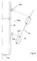
- Figure 6 also shows in detail - set out the example of compressed air nozzles 33, which are located directly on the outer circumference of a suction lance 39, but not limited thereto - on the one hand, the mode of action of the different far radially outwardly acting compressed air jets 32, the upper Compressed air jets 32a of the upper nozzles 33a radially outwardly act as the lower beams 32b and thereby the mentioned conical shape of the suction hole 18 is achieved despite non-conical arrangement of the nozzles 33 a, b.
- Compressed air jet 32a is not always directed in the same direction, but runs annular around a central axis and thus processed a much larger Circular surface or annular surface on the surface of the suction hole 18, as it the cross section of the compressed air jet 32a, b corresponds directly. additionally and / or instead, the compressed air jet 32 may also pulsate to Reduced compressed air consumption to achieve an approximately equally good effect.
- Fig. 7 shows a construction in which, e.g. annular retaining element 21 ' a plurality of intake openings 4a, b distributed over a larger area annularly and possibly also at different altitudes, e.g. along a virtual cone, are arranged as a suction head 4 ":
- the free lower ends of the suction openings 4a, b ... are, or on a reverse as in Figure 1 frusto-conical Suction head 4 can distributed over the circumference a plurality of suction openings 4a, b ... - possibly also in several altitudes - be present.
- compressed air nozzles 33 are again arranged on the holding element 21 '. which act on the environment of the suction openings 4a, b ... with compressed air to solve the local bulk material 13 and to the suction openings 4a, b ... flow allow.
- the suction openings 4a, b ... preferably with a - not shown - central suction hose connected, either the sum the cross sections of the suction openings 4a, b ... is smaller than the cross section of this common suction hose 16 or the individual suction openings 4a, b ... be alternately from the negative pressure of the central suction hose applied.
- the holding element 21 'can simultaneously for securing the upper edge of the Serve container 6, which are using the rope 3 'tightened and pulled up can, of course, in alternation with the lowering of the intake ports 4a, b ... on the surface of the bulk material 13.
- FIG. 8 shows, in a detailed representation to FIGS. 1 a, b, a possibility for the Deflection pulley 8 for the rope 3 of the suction head in the horizontal plane circulate circular, without thereby the suction head 4 itself its own axis turns. This makes it possible, the suction head 4 within the Container 6 a larger workspace than horizontally unchanged Work off position.
- a rotary drive of the rotary plate 42 in a very simple way and Way be realized, for example, that with the rotary plate 42 a Rope winding roller 44 is rotatably connected, on which a rope 3 "is wound, which at any suitable point with the rope 3 for lifting and lowering the suction head is connected.
- the rope 3 "wound on the Winder 44 up or down, including the winding roller 44 in the winding of a not shown spring, for example a spirally wound flat spiral spring, is biased, so that with the compressed air nozzles acting radially to the side equipped suction head spirals down into the container and the bulk material 13 lowered into it, creating only very thin peripheral walls of the Bulk material 13 remain, which easily collapse or brought to collapse can be.
- a not shown spring for example a spirally wound flat spiral spring
Abstract
Description
Die Erfindung betrifft eine Vorrichtung und ein Verfahren zum Entleeren von Schüttgut aus flexiblen, insbesondere sack- oder beutelartigen Behältnissen.The invention relates to an apparatus and a method for emptying Bulk goods made of flexible, in particular bag or bag-like containers.
In vielen technischen Bereichen liegen die zu verarbeitenden Ausgangsprodukte als Schüttgut vor. Dies ist z.B. der Fall beim Rohmaterial für Spritzgussmaschinen, in denen Kunststoff verspritzt wird, wobei das Kunststoff-Granulat oder -Pulver in der Regel in sogenannten Big-Bags, also großen sackartigen Behältnissen, angeliefert wird.In many technical areas are the starting materials to be processed as bulk material. This is e.g. the case of raw material for injection molding machines, in which plastic is sprayed, wherein the plastic granules or powder in usually in so-called big bags, so large bag-like containers, is delivered.
Eine andere Anlieferungsform sind sogenannte Oktabins, also Behälter mit einer festen, achteckigen Umfangswand, in denen der flexible Innenbehälter in Form eines Foliensackes, der mit Granulat gefüllt ist, angeordnet ist.Another delivery form are so-called octabins, so containers with one solid, octagonal peripheral wall in which the flexible inner container in shape a film bag, which is filled with granules, is arranged.
Gleiches gilt für andere Verwendungszwecke wie etwa PVC-Pulver für die Herstellung von PVC-Kunststoffteilen und Harzrohstoffen als Rohmaterial für die Herstellung von Klebstoffen.The same applies to other uses such as PVC powder for the Production of PVC plastic parts and resin raw materials as raw material for the Production of adhesives.
Entleervorrichtungen bestehen dabei üblicherweise aus einem galgenförmigen oder portalförmigen Grundgestell, unter welches der Behälter gestellt wird. Vom Grundgestell aus wird von oben her eine Absaugvorrichtung in das oben offene Behältnis eingeführt, und mittels Absaugen über einen Absaugschlauch das Schüttgut zur gewünschten Stelle transportiert.Emptying devices usually consist of a gallows-shaped or portal-shaped base frame, under which the container is placed. from Base frame is from above a suction device in the open top Introduced container, and by means of suction through a suction hose the Bulk goods transported to the desired location.
Als Absaugvorrichtung dient im einfachsten Fall ein Saugrohr, welches jedoch an seinem vorderen Ende nur einen kleinen Durchmesser besitzt und deshalb über den demgegenüber vergleichsweise großen Oberflächenbereich des Behälters, der größer als 1 m2 sein kann, in Querrichtung und auch in der Vertikalen von einer Bedienperson nachgeführt werden muss.The suction device used in the simplest case, a suction tube, which, however, has only a small diameter at its front end and therefore over the comparatively large surface area of the container, which may be greater than 1 m 2 , in the transverse direction and also in the vertical of an operator must be tracked.
Weitere Probleme liegen im Ansaugen des Foliensackes durch das Saugrohr und das mangelnde Nachrutschen des Schüttgutes bei nur noch geringem Restfüllstand im Gebinde.Further problems are in the suction of the film bag through the suction pipe and the lack of slipping of the bulk material with only a low residual level in the container.
Deshalb wird anstelle eines einfachen Saugrohres häufig ein demgegenüber verbreiterter Saugkopf verwendet, der mit einer größeren Außenfläche am umgebenden Schüttgut anliegt oder auf diesem Schüttgut schwimmt, wobei vorzugsweise noch Vibrationen in das Schüttgut eingebracht werden, um dieses überhaupt oder besser rieselfähig zu machen, da die Vibrationen eine Fluidisierung des Granulates bewirken sollen.Therefore, instead of a simple suction tube often a contrast widened suction head used with a larger outer surface at surrounding bulk material or floats on this bulk material, wherein preferably still vibrations are introduced into the bulk material to this ever or better to make free-flowing, since the vibrations a To cause fluidization of the granules.
Gleichzeitig wird das sackartige, flexible Behältnis am oberen Rand hochgezogen, wodurch die Flanken des Behältnisses zunehmend steiler werden, was noch dadurch begünstigt werden kann, dass der Halterahmen, an dem der obere Rand des Behältnisses befestigt wird, einen geringeren Durchmesser besitzt als das flexible Behältnis im gefüllten Zustand.At the same time, the bag-like, flexible container is pulled up at the upper edge, whereby the flanks of the container are getting steeper, what else This can be favored by the fact that the support frame to which the upper edge the container is attached, has a smaller diameter than that flexible container in the filled state.
Dennoch gibt es Schüttgüter, deren Körner eine sehr hohe Reibung gegeneinander sowie gegenüber einem anderen Gegenstand, etwa einer Absaugvorrichtung, besitzen, so dass trotz aller vorgenannter Maßnahmen unterhalb der Absaugvorrichtung bei solchen Schüttgütern ein so großer Freiraum mangels Nachrutschen von Schüttgut entstehen kann, dass ein weiteres Absaugen nicht gelingt. Nevertheless, there are bulk solids whose grains are very high in friction against each other as well as to another object, such as a suction device, own, so that despite all the above measures below the Suction device in such bulk materials such a large space lack Slippage of bulk material may occur that further suction does not succeed.
Daneben sind auch einfachere Entleervorrichtungen bekannt, bei denen - wiederum nur mit Hilfe des beschriebenen einfachen Saugrohres - der Behälter leergesaugt werden soll und zu diesem Zweck der Behälter auf einer Grundplatte steht, die gekippt und dadurch schräg gestellt werden soll, um ein Sammeln des Schüttgutes in der tiefliegenden Ecke und dortiges Absaugen zu ermöglichen, was jedoch nur bei leicht handhabbaren Materialien funktioniert.In addition, simpler emptying devices are known in which - again only with the help of the described simple suction tube - the container should be sucked empty and for this purpose the container on a base plate stands, which is to be tilted and thereby inclined to a collecting of the Bulk material in the low-lying corner and suction there to allow what however only works with easily manageable materials.
Es ist daher die Aufgabe gemäß der vorliegenden Erfindung, ein Verfahren sowie eine diesbezügliche Vorrichtung zu schaffen, die auch bei nicht bzw. schwer rieselfähigen Schüttgütern ein Absaugen aus den bekannten, oben offenen flexiblen Behältnissen nach oben ohne manuelle Unterstützung ermöglichen.It is therefore the object of the present invention, a method and to create a device in this regard, even if not or difficult free-flowing bulk materials sucking from the known, open-topped flexible containers up without manual support.
Diese Aufgabe wird durch die Merkmale der Ansprüche 1 bzw. 19 gelöst.
Vorteilhafte Ausführungsformen ergeben sich aus den Unteransprüchen.This object is solved by the features of
Der Grundgedanke des erfindungsgemäßen Verfahrens bzw. der erfindungsgemäßen Vorrichtung besteht darin, dass das Schüttgut, dessen Partikel teilweise zusammengepresst sind und zusammenkleben und daher je nach existierenden Randbedingungen nicht mehr zu der Absaugöffnung der Absaugvorrichtung nachrutschen, durch Beaufschlagen mittels Druckluft stärker vereinzelt werden. Vereinzeln muss dabei nicht unbedingt das Vereinzeln bis zu einem einzelnen Partikel bedeuten, sondern auch kleinere Sammelballungen von Partikeln, die von ihrer Umgebung getrennt werden, sind in der Regel schon handhabbar. The basic idea of the method according to the invention or the invention Device is that the bulk material whose particles partially are compressed and stick together and therefore depending on existing ones Boundary conditions no longer to the suction of the suction device slipping, be separated by applying more compressed air. Singling does not necessarily mean singling down to a single one Particles mean, but also smaller accumulations of particles from particles Their environment are usually already manageable.
Zu diesem Zweck wird das Schüttgut in der Umgebung der Absaugvorrichtung durch Beaufschlagen mittels Druckluft gelockert, also die Partikel voneinander gelöst, um deren Nachrutschen in Richtung Absaugöffnung zu erleichtern oder gar zu fördern, letzteres indem die Richtung der Drucklufteinbringung eine abwärts gerichtete Komponente aufweist.For this purpose, the bulk material in the vicinity of the suction device loosened by applying compressed air, so the particles from each other solved to facilitate their slippage in the direction of suction or even To promote, the latter by the direction of the compressed air introduction a downward directed component.
Konkret bildet sich beim Absaugen des Schüttgutes von dessen Oberfläche her ein Absaugloch, dessen Wände bei zu starkem Aneinanderhaften der Partikel nicht mehr nachrutschen, so dass die Druckluft, vorzugsweise in Form einzelner, möglich kraftvoller und daher punktueller Druckluftstrahlen, gegen die Wand des Absaugloches gerichtet sind, vorzugsweise von der Absaugvorrichtung, beispielsweise dem Saugkopf aus, ausgehend.Concretely forms during the suction of the bulk material from its surface a suction hole whose walls are too strong adherence of the particles no longer slip, so that the compressed air, preferably in the form of individual, possible powerful and therefore selective compressed air jets, against the wall of the Suction holes are directed, preferably from the suction device, for example, the suction head, starting.
Um dabei einen nennenswerten Abtrag zu erzeugen, werden vorzugsweise mehrere Druckluftstrahlen, z. B. über den Umfang der Saugvorrichtung verteilt und/oder über deren Höhe verteilt, angeordnet.In order to produce a significant removal, are preferably several compressed air jets, z. B. distributed over the circumference of the suction device and / or distributed over the height thereof, arranged.
Um über eine ausreichende Kraftwirkung im Schüttgut zu erzeugen, sind die Druckluftstrahlen vorzugsweise mit einer geringen Auftrefffläche und damit mit einer Spitzkegelcharakteristik, also möglichst punktuell, ausgebildet, und der Strahl tritt mit einem Druck von 2 - 8, insbesondere 4 - 6 bar aus der Düse aus.To produce a sufficient force in the bulk material, the Compressed air jets preferably with a small impact surface and thus with a pointed cone characteristic, that is as punctual, trained, and the Jet exits the nozzle at a pressure of 2-8 bar, especially 4-6 bar.
Die Richtung der Düsen ist vorzugsweise schräg nach unten gerichtet, beispielsweise unter einem Winkel von 20 - 80°, insbesondere von 30 - 60°, insbesondere von 40 - 50°.The direction of the nozzles is preferably directed obliquely downwards, for example at an angle of 20-80 °, in particular of 30-60 °, in particular from 40 - 50 °.
Die Beaufschlagung mit Druckluft muss nicht ständig erfolgen, sondern vorzugsweise nur dann, wenn die Absaugvorrichtung aktiviert ist, also mit Unterdruck beaufschlagt ist, da sonst das in Bewegung gebrachte Granulat zuviel Staub an die Umgebung abgeben würde, der dann nicht von der Absaugvorrichtung aufgesaugt würde, was für die Menschen in der Umgebung nicht zumutbar oder gar gefährlich ist. Dementsprechend ist auch während des Absaugvorganges das von der Absaugvorrichtung abgeförderte Luftvolumen pro Zeiteinheit größer als das von der Druckluftbeaufschlagung zugeführte Luftvolumen.The application of compressed air does not always have to be done, but preferably only when the suction device is activated, ie with Negative pressure is applied, otherwise the agitated granules too much Dust would give off to the environment, then not from the suction device would be sucked up, what for the people in the area not reasonable or even dangerous. Accordingly, also during the Absaugvorganges the evacuated from the suction air volume per Time unit greater than the volume of air supplied by the compressed air supply.
Auch während der prinzipiell aktivierten Phase der Druckluftbeaufschlagung muss diese Druckluftbeaufschlagung nicht permanent geschehen. Auch stoßweise Beaufschlagung kann zu einem annähernd gleichen Effekt, jedoch mit geringerem Druckluftverbrauch, führen. Dauer und Abstand der einzelnen Druckluftstöße können manuell eingestellt werden, beispielsweise in Abhängigkeit der Art und des Zustandes des zu lösenden Granulates, oder auch automatisch gesteuert in Abhängigkeit von der durch den Saugschlauch abgeführten Menge an Schüttgut pro Zeiteinheit, was durch einen Sensor automatisch erfasst werden kann.Even during the principle activated phase of the compressed air supply must This compressed air supply does not happen permanently. Also intermittently Applying can be approximately the same effect but with less Compressed air consumption, lead. Duration and distance of the individual compressed air surges can be set manually, for example, depending on the type and the state of the granules to be dissolved, or automatically controlled in Dependence on the amount of bulk material discharged through the suction hose per unit of time, which can be detected automatically by a sensor.
Zusätzlich kann das Absaugen gefördert werden, indem die Absaugvorrichtung selbst oder der Untergrund des Behältnisses Vibrationen in das Granulat einbringt und/oder die Absaugvorrichtung immer wieder, vorzugsweise periodisch und automatisch, angehoben, entweder nur innerhalb des Absaugloches angehoben oder bis über die Oberkante des Absaugloches angehoben und anschließend wieder auf das Schüttgut, also z. B. den Boden des Absaugloches, abgesenkt wird, vorzugsweise jedoch seitlich versetzt zur ursprünglichen Position.In addition, the suction can be promoted by the suction device itself or the substrate of the container brings vibrations into the granules and / or the suction device over again, preferably periodically and automatically raised, either raised only within the suction hole or raised above the top of the suction hole and then back to the bulk, so z. B. the bottom of the suction, lowered is, but preferably offset laterally to the original position.
Auch eine Schrägstellung der Grundplatte, auf der der Schüttgutbehälter steht, ist möglich.Also, an inclination of the base plate on which the bulk material container is, is possible.
Dabei besteht das Ziel darin, den Umgebungsbereich der Absaugvorrichtung trotz der einzelnen Punkteeinwirkung des einzelnen Druckluftstrahles flächig zu bearbeiten, um möglichst auf der gesamten Fläche des Absaugloches ein Vereinzeln der Partikel und damit ein Nachrutschen des Schüttgutes nach unten in Richtung Absaugöffnung des Saugkopfes zu ermöglichen. Zu diesem Zweck muss der Wirkungsbereich der Düsen nicht die Absaugöffnung selbst erreichen, und die Wirkungsbereiche müssen sich auch nicht direkt aneinander anschließen, da bei punktueller Auflockerung auch die Bereiche zwischen den einzelnen Auflockerungsbereichen an Stabilität verlieren und anschließend ebenfalls einstürzen. The goal is to spite the environment of the suction device the individual point effect of the individual compressed air jet area to edit as much as possible over the entire area of the suction hole Separating the particles and thus slipping the bulk material downwards to allow in the direction of the suction opening of the suction head. To this end the effective area of the nozzles does not have to reach the suction opening itself, and the spheres of influence do not have to connect directly with each other, because with selective loosening also the areas between the individual Loosen loosening areas of stability and then likewise collapse.
Dennoch kann die flächige Wirkung durch Unterschiedliche Maßnahmen vergrößert werden, sei es durch kreisende Strahlrichtung der Druckluftdüsen oder durch mechanische Vorrichtungen, z. B. Leitvorrichtungen, die ihre Richtung ändern.Nevertheless, the area effect can be increased by different measures be it by circular jet direction of the compressed air nozzles or through mechanical devices, e.g. B. Guiding devices that change direction.
Auch in diesem Zusammenhang ist es hilfreich, die Unterseite der Saugvorrichtung kegelförmig oder kegelstumpfförmig auszubilden, da dies einer Annäherung an einen sich bildenden nachrutschenden umgekehrten Kegel als Absaugloch am nächsten kommt, und hierdurch das Nachrutschen zur Absaugöffnung erleichtert wird.Also in this context, it is helpful to the bottom of the suction device cone-shaped or frustoconical form, as this one Approaching a forming inverted cone as a slipping post Suction hole comes closest, and thereby the slipping to the suction is relieved.
Diese Kegelform kann jedoch auch anders erreicht werden, indem beispielsweise die weiter oben angeordneten Düsen, trotz gleichen radialen Abstandes zur vertikalen Mitte der Saugvorrichtung, einen größeren radialen Wirkungsbereich aufweisen als die tieferliegenden, und dadurch mittels der sich addierenden Wirkungsbereiche ein virtueller kegelförmiger Beeinflussungsrahmen geschaffen wird. Dies kann insbesondere dann hilfreich sein, wenn die Außenkontur der verwendeten Saugvorrichtung selbst nicht kegelförmig ist, beispielsweise die Saugvorrichtung ein einfaches Saugrohr mit einer Öffnung am freien Ende ist, an dessen Außenumfang angeordnet und vorzugsweise radial nicht abstehend die Düsen angeordnet sind, z. B. in zwei oder drei in Längsrichtung beabstandeten Ebenen.However, this conical shape can also be achieved differently, for example by the nozzles arranged further above, despite the same radial distance to vertical center of the suction device, a larger radial impact area have as the underlying, and thereby by means of the adding Impact areas created a virtual conical influence frame becomes. This can be helpful in particular if the outer contour of the used suction device itself is not conical, for example, the Suction is a simple suction tube with an opening at the free end, on arranged the outer periphery and preferably not radially projecting the Nozzles are arranged, for. B. spaced in two or three longitudinally Levels.
Die Druckluftdüsen werden vorzugsweise über eine zentrale Druckluftleitung mit Druckluft versorgt und von einem vorhandenen stationären Druckluftnetz aus mit Druckluft beliefert. Die zentrale Versorgungsleitung wird vorzugsweise an dem ebenfalls flexiblen Saugschlauch befestigt werden und sich zusammen mit diesem bewegen.The compressed air nozzles are preferably via a central compressed air line with Compressed air supplied and from an existing stationary compressed air network with Compressed air supplies. The central supply line is preferably at the Also flexible suction hose can be attached and fit together with this move.
In einer bevorzugten Ausführungsform sind die Druckluftdüsen und deren Versorgungsleitungen an einer vorhandenen Saugvorrichtung, insbesondere einem Saugkopf, nachrüstbar, beispielsweise mit Hilfe von Haltebügeln oder Oberseite, Außenseite oder Unterseite des Saugkopfes aufschraubbar oder anderweitig befestigbar.In a preferred embodiment, the compressed air nozzles and their Supply lines to an existing suction device, in particular a suction head, retrofittable, for example by means of brackets or The top, outside or bottom of the suction head can be screwed on or otherwise attachable.
Der Druck des Druckluftnetzes wird für die Verwendung an den Druckluftdüsen mittels eines einstellbaren Reduzierventils gemindert.The pressure of the compressed air network is for use on the compressed air nozzles reduced by means of an adjustable reducing valve.
Vorzugsweise können alle Funktionen der Druckbeaufschlagung mittels einer Steuerung, vorzugsweise einer elektrischen Steuerung, geregelt werden. Im einfachen Fall jedoch wird keine elektrische Steuerung benötigt, sondern die Unterdruckbeaufschlagung im Saugschlauch öffnet ihrerseits direkt das Druckluftventil für die Versorgung der Druckluftdüsen, während die Stärke der Druckminderung manuell durch die Einstellung am Druckminderungsventil vorgegeben wird. Pulsierender Strahl und ggf. auch rotierender Strahl können allein durch die konstruktive Gestaltung der Düsen vorgegeben sein, wobei die Düsen zusätzlich mechanisch manuell umstellbar sein können, z. B. zwischen permanentem Strahl und pulsierendem Strahl, zwischen stillstehendem Strahl und rotierendem Strahl.Preferably, all functions of the pressurization by means of a Control, preferably an electrical control, are regulated. in the simple case, however, no electrical control is needed, but the Negative pressure in the suction hose in turn opens directly Compressed air valve for the supply of compressed air nozzles, while the strength of the Manually reduce pressure by adjusting the pressure reducing valve is given. Pulsating beam and possibly also rotating beam can be predetermined solely by the structural design of the nozzle, wherein the In addition, nozzles may be mechanically manually adjustable, z. B. between permanent beam and pulsating beam, between stationary beam and rotating beam.
Falls eine elektrische Steuerung verwendet wird, ist diese integriert in die üblicherweise bereits vorhandene elektrische Steuerung, welche die Absaugvorrichtung, den Hebemechanismus für den Saugkopf und/oder den Hebemechanismus für den Behälter steuert.If an electrical control is used, it is integrated into the usual existing electrical control, which the suction device, the lifting mechanism for the suction head and / or the lifting mechanism for controls the container.
Eine Möglichkeit, die von der Saugvorrichtung bearbeitete Grundfläche zu vergrößern, besteht darin, die Saugvorrichtung im Behälter horizontal zu bewegen, z. B. kreisen zu lassen. Eine andere Möglichkeit besteht darin, die Saugvorrichtung in ihrem Durchmesser sehr groß auszugestalten und zu diesem Zweck vorzugsweise mehrere Absaugöffnungen über die Grundfläche verteilt anzuordnen, die entweder jede für sich so klein sind, dass die Gesamtfläche der Absaugöffnungen kleiner ist als der Querschnitt des zentralen, abfördernden Saugschlauches oder die einzelnen Absaugöffnungen periodisch nacheinander, aber nie alle gleichzeitig, vom Unterdruck beaufschlagt werden. One way to access the footprint machined by the suction device Enlarge, is the suction device in the container to horizontal move, z. B. to let circle. Another possibility is the Suction device in their diameter very large and to design this Purpose preferably a plurality of suction openings distributed over the base either individually are so small that the total area of the Suction openings is smaller than the cross section of the central, promotional Suction hose or the individual suction openings periodically one after the other, but never all at the same time, be acted upon by the negative pressure.
Ausführungsformen gemäß der Erfindung sind anhand der Zeichnungen nachfolgend näher beschrieben. Es zeigen:
- Fig. 1 a:
- das Entleeren des Behälters mittels eines auf der Unterseite kegelförmigen Saugkopfes, der mit Druckluftdüsen ausgestattet ist,
- Fig. 1 b:
- denselben Behälter im fast vollständig entleerten und hochgezogenen Zustand,
- Fig. 2:
- eine andere Bauform des Saugkopfes,
- Fig. 3:
- eine einfache Sauglanze ausgestattet mit Druckluftdüsen mit Hebevorrichtung,
- Fig. 4
- eine mit Druckluftdüsen ausgestattete Saulanze ohne Hebevorrichtung in einem schräg stellbaren Behälter,
- Fig. 5:
- eine mechanisch rotierende Absaugöffnung,
- Fig. 6:
- die Wirkung rotierender Druckluftstrahlen,
- Fig. 7:
- ein Saugkopf mit mehreren Absaugöffnungen, und
- Fig. 8:
- eine Detaillösung zur Querverlagerung.
- Fig. 1 a:
- the emptying of the container by means of a conical on the bottom suction head, which is equipped with compressed air nozzles,
- Fig. 1b:
- the same container in the almost completely deflated and raised state,
- Fig. 2:
- another design of the suction head,
- 3:
- a simple suction lance equipped with compressed air nozzles with lifting device,
- Fig. 4
- a sump equipped with compressed air nozzles without lifting device in a tiltable container,
- Fig. 5:
- a mechanically rotating suction opening,
- Fig. 6:
- the effect of rotating compressed air jets,
- Fig. 7:
- a suction head with several suction openings, and
- Fig. 8:
- a detailed solution for transverse displacement.
In den Figuren 1 zeigen die Figuren 1 a und 1 b die jeweilige Entleervorrichtung in
der Seitenansicht, einmal bei noch fast vollständiger Füllung des Behältnisses 6
mit Schüttgut 13 und einmal bei fast vollständig geleertem Behältnis 6.In FIGS. 1 a and b show the respective emptying device in FIG
the side view, once with almost complete filling of the container. 6
with
Das Behältnis 6 ist dabei ein in einem Oktabin 7, also mit festen Behälterwänden,
aufgenommenen Foliensack, der auf einer Palette unter dem Überbau der
Entleervorrichtung steht. Die Entleervorrichtung umfasst dabei jeweils einen Halterahmen
1, der horizontal ringförmig zentrisch über dem sackförmigen Behältnis 6
angeordnet ist und den oberen Rand des Behältnisses 6 mittels eines Halteelements
21 in Form eines um den Halterahmen 1 umlaufenden Klemmgurtes
festhält.The
Der Halterahmen 1 wird mittels eines Seilzuges 3' nach oben gezogen, der über
Umlenkrollen 9' entlang der Querstrebe 19 und der Vertikalstrebe 20 entlanggeführt
ist und mit einem Behälterzylinder 24 verbunden ist, mit dessen Hilfe der
Halterahmen 1 hochgezogen und damit - wie in Fig. 1 b ersichtlich - dessen
Seitenwände geradegezogen werden können.The
Da der Halterahmen 1 einen geringeren Durchmesser als das Behältnis 6 im
gefüllten Zustand besitzt, werden die Seitenwände des sackförmigen Behältnisses
vor allem in dem Bereich oberhalb des Schüttgutes 13 nach innen gezogen, bis
- gegen Ende des Entleervorganges - sie an dem Saugkopf 4 außen anliegen.Since the holding
Der Saugkopf 4, von dem der Saugschlauch 16 nach oben wegführt, ist ebenfalls
mittels eines Seilzuges 3, welcher über analoge Umlenkrollen 8, 9 geführt ist, zu
einem weiteren Hubzylinder 14 geführt, welcher dem Anheben und Absenken des
Saugkopfes dient.The
Beide Zylinder 14, 24 sind vertikal an der Vertikalstrebe 20, insbesondere an
deren vom Oktabin 7 abgewandten Rückseite, befestigt, und werden über eine
Steuerung 17 angesteuert, die entweder an der Vertikalstrebe 20 oder an einem
separaten Hängekabel befestigt ist.Both
Mittels der Steuerung 17 wird z.B. eingestellt, ob und wie oft der Saugkopf 4 aus
dem Schüttgut 13 herausgezogen und erneut auf dieses abgesenkt wird, und/oder
wie tief der Saugkopf 4 nach dem Aufsetzen auf der Oberfläche des Schüttgutes
13 versinken darf, bevor das Anheben und Herausziehen aus dem
Schüttgut erfolgt, was ja jeweils mehrfach hintereinander durchgeführt wird. By means of the
Ferner kann an der Steuerung 17 einstellbar sein, aus welcher Höhe der Saugkopf
4 beim Aufsetzen auf die Oberfläche des Schüttgutes fallengelassen wird.Furthermore, it can be adjustable on the
Um den Saugkopf 4 mittels des Seilzuges 3 über die gewünschte vertikale Distanz
von knapp unterhalb der Querstrebe 19 bzw. 19' bis auf den Boden des Oktabins
absenken zu können, ist der Seilzug 3 am Ende der Kolbenstange des
Hubzylinders 14 nicht direkt befestigt, sondern an dessen Ende nur über eine
weitere Rolle 26 geführt, und endet an einem ortsfesten Punkt.To the
Dadurch wird eine Übersetzung dergestalt erzielt, dass bei Verlagerung der
Kolbenstange des Zylinders 14 um eine Längeneinheit der Saugkopf 4 um zwei
Längeneinheiten bewegt wird.As a result, a translation is achieved such that when relocating the
Piston rod of the
Damit ist die Höhe der Vertikalstrebe 20 bzw. 20" ausreichend zur Befestigung
eines etwa halb so langen Zylinders 14 daran, wenn somit die andere Hälfte der
Höhe der Vertikalstrebe 20 bzw. 20" als Bewegungsweg der Rolle zur Verfügung
steht.Thus, the height of the
Neu an dieser Entleervorrichtung ist, dass der Saugkopf 4 zusätzlich mit
Druckluftdüsen 33 ausgestattet ist, die Druckluftstrahlen 32 vom Saugkopf 4 aus
radial nach außen gegen das Schüttgut 13 richten, und zwar vorzugsweise schräg
nach unten gerichtet, gegen die Wände des Saugloches 18, welches gebildet wird
durch die Absaugung von Schüttgut 13 von oben her in der Mitte des Behälters.New to this emptying is that the
Dadurch wird das Material an der Oberfläche der Wände des Absaugloches 18
gelockert und fließt entlang der Wände nach unten zum tiefsten Punkt des
Absaugloches 18 und damit in den Bereich der Saugöffnung 4a des
Saugkopfes 4, welcher sich am tiefsten Punkt des die Form eines umgekehrten
Kegelstumpfes aufweisenden Saugkopfes 4 befindet und dort aufgrund seiner
Vereinzelung (Fluidisierung) abgesaugt werden kann.As a result, the material on the surface of the walls of the suction hole 18th
loosened and flows along the walls down to the lowest point of the
Dabei besteht das Ziel darin, einerseits immer ausreichend viel loses, also nicht
zusammengeklebtes oder anderweitig verfestigtes Schüttgut 13 in den Bereich
der Absaugöffnung 4a des Saugkopfes 4 zu bringen, und andererseits, das
entstehende Saugloch 18 so groß wie möglich zu gestalten, um die verbleibenden
außen herumstehenden Wände an Schüttgut 13 so dünn wie möglich zu bilden,
was deren Einstürzen erleichtert, was durch Hochziehen des sackartigen
Behältnisses 6 und damit nach innen drücken der Wände ständig oder in
zeitlichen Abständen gefördert wird.The goal here is, on the one hand, always plenty of enough, so not
glued or otherwise solidified
Am Saugkopf 4, nämlich entlang dessen Außenumfanges, sind mehrere
Druckluftdüsen 33 in den Figuren 1 a und 1b in zwei verschiedenen vertikalen
Ebenen angeordnet.On the
Alle Druckluftdüsen 33 werden über eine zentrale Versorgungsleitung 35, die
vorzugsweise entlang des Saugschlauches 16 zum Saugkopf 4 geführt wird, mit
Druckluft versorgt.All
In der oberen Ebene sind die Saugdüsen 33 mittels Haltebügeln 34, die immer
zwei oder mehr Düsen 33 tragen, entlang der oberen Umlaufkante des
Saugkopfes 4 befestigt, beispielsweise indem die Haltebügel 34 auf der Oberseite
des Saugkopfes 4 verschraubt sind, so dass die Düsen 33 knapp oberhalb der
Oberkante positioniert sind.In the upper level are the
Weitere Düsen 33 sind in einer zweiten, tieferliegenden Ebene entlang der
Kegelfläche des Saugkopfes angeordnet. Es können noch in weiteren, einer z.B.
dritten noch tieferliegenden Ebene, Düsen 33 angeordnet werden, die dann noch
näher zur Saugöffnung 4a hin positioniert sind.
Die Düsen 33 sind dabei jeweils radial nach außen und schräg unten gerichtet,
und vorzugsweise umso stärker nach unten gerichtet, je tiefer und näher an der
Saugöffnung 4a sie an dem Saugkopf 4 angeordnet sind.The
Mittels Unterstützung der Saugdüsen 33 arbeitet sich der Saugkopf 4 wie
vorbeschrieben im Schüttgut 13 nach unten, wobei die das Saugloch 18
umgebenden Wände an Schüttgut 13 einstürzen bzw. zum Einsturz gebracht
werden und nach unten nachrutschen, bis der quasi vollständig entleerte Zustand
gemäß Fig. 1 b erreicht ist, indem das sackartige Behältnis 6 am Außenumfang
des Saugkopfes 4 anliegt und höchstens im verbleibenden Restabstand zwischen
der Unterseite des Saugkopfes 4 und dem dort verlaufenden Behältnis 6 noch
Reste an Schüttgut 13 in sehr kleiner Menge vorhanden sind.By means of the
Demgegenüber zeigt Fig. 2 eine Entleervorrichtung, bei der das Traggestell 43
nicht nur aus einer Vertikalstrebe 20 und einer oben davon abstrebenden frei
auskragenden Querstrebe 19 besteht, sondern portalförmig mit zwei aufstrebenden
Vertikalstreben 20 und einer diese verbindenden, beidseitig befestigten
Querstrebe 19' besteht.In contrast, Fig. 2 shows an emptying device, wherein the
Auch ist hier das Hebezeug 5, welches den Saugkopf 4' mittels eines Seilzuges 3 heben und senken kann, mittels einer Handkurbel antreibbar. Auch das Halteelement 21' ist etwas anders gestaltet, nämlich als Ring mit Karabinern zum Einhängen der Tragegriffe des als Behältnis 6' hier verwendeten Big-Bags.Also here is the hoist 5, which the suction head 4 'by means of a cable. 3 can lift and lower, drivable by means of a hand crank. That too Retaining element 21 'is designed somewhat differently, namely as a ring with carabiners for Hanging the carrying handles of the container 6 'used here as big bags.
Der Saugkopf 4' ist ebenfalls anders gestaltet, und besteht im Wesentlichen aus
einer Sauglanze 39, also einem Rohrstück, dessen offenes unteres Ende die
Saugöffnung 4a darstellt, und an dessen oberes Ende der flexible Saugschlauch
16 angeschlossen ist.The suction head 4 'is also designed differently, and consists essentially of
a
Um die Sauglanze 39 herum ist ein Gewicht 25 angeordnet, in Form einer Hülse
mit im Längsschnitt kegeligem oder wie gezeichnet doppelt-kegeligem
Querschnitt, um wiederum eine kegelförmige Unterseite ähnlich wie beim Saugkopf
4 der Fig. 1a/b zu erhalten, was das Nachfließen von Schüttgut zur unteren
Saugöffnung 4a erleichtert.Around the
Auch hier sind Druckluftdüsen 33, die schräg nach außen unten weisen, an der
Oberfläche, in diesem Fall der nach unten gerichteten Kegelfläche des Gewichtskörpers
25 des Saugkopfes 4' - diesmal nur in einer einzigen vertikalen Ebene
umlaufend - angeordnet. Die Düsen 33 können dabei über Leitungen oder
Bohrungen im Inneren des Gewichtskörpers 25 mit der von der Versorgungsleitung
35 gelieferten Druckluft versorgt werden.Also here are compressed
Im Übrigen entspricht die Entleervorrichtung und vor allem hinsichtlich deren Druckluftausstattung derjenigen der Figuren 1.Incidentally, the emptying device and above all with regard to their Compressed air equipment of those of the figures 1.
Als weitere Besonderheit ist in Figur 2 aufgrund einer nur kleinen oberen Öffnung
des Behälters 6' eine Zuluftleitung 26 von außerhalb des Behälters 6' zum
Saugkopf 4' geführt, welche Zuluft nahe der Saugöffnung 4a zur Verfügung stellt,
um zu vermeiden, dass der Saugvorgang unterbrochen wird wegen einem Mangel
an nachströmender Luft.Another special feature is in Figure 2 due to a small upper opening
of the container 6 'an
Figur 3 zeigt eine Entleervorrichtung, bei der zwar das Traggestell 43 und auch
die Druckluftversorgung derjenigen der Figur 1 entspricht, jedoch der Saugkopf 4"
anders gestaltet ist:
An der Sauglanze 39 ist jedoch werden ein Gewicht noch ein eine spezielle
Außenkontur bildender Formkörper befestigt, sondern in zwei übereinander
angeordneten Ebenen sind an der Sauglanze 39 in jeder Ebene jeweils über dem
Umfang verteilt mehrere Saugdüsen 33 an der Sauglanze 39 angeordnet, und
zwar von unten nach oben mit zunehmendem radialen, horizontalen Abstand von
der in Figur 3 senkrecht stehenden Sauglanze 39.At the
In der unteren Ebene sind die Düsen 33 von dem unteren Ende, also der
Saugöffnung 4a, nach oben versetzt umlaufend direkt auf dem Außenumfang der
Sauglanze 39 angeordnet.In the lower level, the
In der oberen Ebene sind die Düsen 33 radial nach außen beabstandet, in
vertikaler Richtung etwa auf Höhe des Überganges zwischen Sauglanze 39 und
flexiblem Saugschlauch 16, angeordnet, beispielsweise wieder mittels der in
Figur 1 erwähnten Haltebügel 34, die auf einem die Sauglanze 39 umgebenden
Ring oder Kreisplatte befestigt sein können und daher - wie bei der Lösung
gemäß Figur 1 oder 2 - an einem herkömmlichen Saugkopf 4, 4' nachrüstbar sind.In the upper plane, the
Durch die zunehmend nach oben radiale Beabstandung der Düsen 33 von der
Mittelachse und damit der Sauglanze 39 befinden sich die Düsen 33 auf einer
virtuellen nach unten gerichteten Kegelfläche, was ebenfalls wieder das
Nachrutschen an Schüttgut auf der Oberseite eines ebenfalls sich meist
kegelförmig ausbildenden Saugloches 18 erleichtert.Due to the increasingly upwardly radial spacing of the
Dagegen zeigt Figur 4 anschaulich, dass sich ein solches kegelförmiges
Absaugloch 18 nicht ausbildet, wenn wie in Figur 4 in mehreren Ebenen an z.B.
der Sauglanze 39 übereinander angeordneten Düsen 33 jeweils den gleichen
seitlichen radialen Abstand zur Mittelachse und damit der Sauglanze 39 besitzen,
indem sie wie in Figur 4 direkt auf dem Außenumfang der Sauglanze 39
angeordnet sind.In contrast, FIG. 4 clearly shows that such a cone-shaped
Dann ergibt sich ein eher kegelförmiges Saugloch 18 um die Sauglanze 39
herum, was in vielen Anwendungsfällen nicht die optimale Form darstellt.Then, a rather
Selbst mit einer radial nicht gestaffelten Anordnung der Düsen 33 kann jedoch die
Ausbildung eines kegelförmigen Saugloches erzielt werden, nämlich dann, wenn
die höherliegenden Düsen 33 einen radial größeren Wirkungsbereich besitzen als
die tieferliegenden und dadurch ein virtuell kegelförmiger Wirkungsbereich in
Summe der in mehreren Ebenen übereinander angeordneten Düsen 33 erzielt
wird.Even with a radially non-staggered arrangement of the
Zusätzlich unterscheidet sich die Lösung gemäß Figur 4 von derjenigen der
Figuren 1 bis 3 dadurch, dass in Figur 4 der aus einer Sauglanze 39 bestehende
Saugkopf, der wie in den Figuren 1 bis 3 mit einem flexiblen Saugschlauch in
Verbindung steht und dessen Druckluftdüsen 33 mittels einer DruckluftVersorgungsleitung
35 versorgt werden, weder selbst an einem anhebbaren
Hebezeug befestigt ist, noch das Behältnis an einem Hebezeug befestigt ist,
welches im vorliegenden Fall aus einem Oktabin 7 mit festen Umfangswänden
besteht.In addition, the solution according to FIG. 4 differs from that of FIG
Figures 1 to 3, characterized in that in Figure 4 of a
Dementsprechend ist auch kein Traggestell für diese Hebezeuge vorhanden,
sondern der Oktabin 7 steht auf einer Grundplatte 23', die mittels eines z.B.
Hydraulikzylinders schräg gekippt werden kann, so dass eine der Unterkanten des
Oktabins 7 dessen tiefsten Punkt darstellt, an dem sich gegen Ende des
Füllungszustandes die Reste an Schüttgut 13 sammeln. Die Schrägstellung wird
erst nach teilweiser Entleerung des Oktabins 7 durchgeführt.Accordingly, there is also no support frame for these hoists,
but the
Um die in den Oktabin 7 gestellte Sauglanze 39 in Ermangelung eines Hebezeuges
wenigstens einigermaßen in Position zu fixieren, ist an der Sauglanze 39
und/oder dem darüber folgenden Saugschlauch 16 eine Einhängevorrichtung 41,
z.B. in Form eines Einhängebügels, angeordnet, mittels welcher die Sauglanze an
der Oberkante des Oktabins 7 eingehängt werden kann.To the asked in
Fig. 5 zeigt eine Lösung mit Saugrohr 16, wobei sich vorzugsweise an den nach
unten außen gekrümmten Abschnitt 16a ein teleskopierbarer Abschnitt 16b zur
Vergrößerung des Wirkradius anschließt. Zusätzlich ist der Abschnitt 16a
gegenüber einem festen, stromaufwärts liegenden Schlauchabschnitt bzw. Rohrabschnitt
16c drehbar befestigt mittels eines Leitrades 27 mit Leitschaufeln 27'.
Die Leitschaufeln 27' sind so gekrümmt, dass ein darüber geführter Luftstrahl, der
in Form z.B. eines Bypasses 28 der Druckluftversorgungsleitung 35 über das
Leitrad 27 geführt wird und dadurch ein umfangsförmiger Rückstoßeffekt dieses
über den Bypass geführten Stromes gegenüber den Leitschaufeln 27' eintritt, die
den beweglichen Teil des Saugrohrs 16 in Drehung versetzen.Fig. 5 shows a solution with
Figur 6 zeigt weiterhin in Detaildarstellung - dargelegt am Beispiel von Druckluftdüsen
33, die sich direkt auf dem Außenumfang einer Sauglanze 39 befinden,
jedoch nicht hierauf beschränkt - einerseits die Wirkungsweise der unterschiedlich
weit radial nach außen wirkenden Druckluftstrahlen 32, wobei die oberen
Druckluftstrahlen 32a der oberen Düsen 33a radial weiter nach außen wirken als
die unteren Strahlen 32b und hierdurch die erwähnte Kegelform des Saugloches
18 erzielt wird trotz nicht-kegelförmiger Anordnung der Düsen 33a, b.Figure 6 also shows in detail - set out the example of
Zusätzlich ist dort der möglichst punktförmige, also möglichst spitzkegelige,
Druckluftstrahl 32a nicht immer in die gleiche Richtung gerichtet, sondern läuft
ringförmig um eine Mittelachse um und bearbeitet damit eine wesentlich größere
Kreisfläche bzw. Kreisringfläche auf der Oberfläche des Saugloches 18, als es
dem Querschnitt des Druckluftstrahles 32a, b direkt entspricht. Zusätzlich
und/oder stattdessen kann der Druckluftstrahl 32 auch pulsieren, um bei
vermindertem Druckluftverbrauch eine annähernd gleich gute Wirkung zu erzielen.In addition, there is the point-like possible, so as possible pointed cone,
Beide Wirkungen, Pulsierung und kegelförmiges Umlaufen, können natürlich auch bei allen anderen körperlichen Bauformen, insbesondere gemäß der Figuren 1 bis 4, verwirklicht werden.Both effects, pulsation and conical circulation, of course, too in all other physical forms, in particular according to the figures 1 to 4, to be realized.
Figur 7 zeigt eine Bauform, bei der an einem z.B. ringförmigen Halteelement 21'
mehrere Ansaugöffnungen 4a, b ringförmig über eine größere Grundfläche verteilt
und ggf. auch in unterschiedlicher Höhenlage, z.B. entlang eines virtuellen Kegels,
als Saugkopf 4" angeordnet sind:Fig. 7 shows a construction in which, e.g. annular retaining element 21 '
a plurality of
Beispielsweise können an dem ringförmigen Halteelement 21' nach unten
ragende Rohrstutzen befestigt sein, deren freie untere Enden die Saugöffnungen
4a, b... sind, oder an einem wie in Figur 1 umgekehrt kegelstumpfförmigen
Saugkopf 4 können über den Umfang verteilt mehrere Absaugöffnungen 4a, b...
- eventuell auch in mehren Höhenlagen - vorhanden sein.For example, on the annular support member 21 'down
be projecting pipe socket, the free lower ends of the
Zusätzlich sind an dem Halteelement 21' wiederum Druckluft-Düsen 33 angeordnet,
die die Umgebung der Saugöffnungen 4a, b... mit Druckluft beaufschlagen
um das dortige Schüttgut 13 zu lösen und zu den Saugöffnungen 4a, b... fließen
zu lassen.In addition,
Dabei sind die Saugöffnungen 4a, b... vorzugsweise mit einem - nicht
dargestellten - zentralen Saugschlauch verbunden, wobei entweder die Summe
der Querschnitte der Saugöffnungen 4a, b... kleiner ist als der Querschnitt dieses
gemeinsamen Saugschlauches 16 oder die einzelnen Saugöffnungen 4a, b...
werden abwechselnd vom Unterdruck des zentralen Saugschlauches
beaufschlagt.In this case, the
Das Halteelement 21' kann gleichzeitig zum Befestigen des oberen Randes des
Behälters 6 dienen, der mit Hilfe des Seiles 3' gestrafft und hochgezogen werden
kann, natürlich im Wechsel mit dem Absenken der Ansaugöffnungen 4a, b... auf
die Oberfläche des Schüttgutes 13.The holding element 21 'can simultaneously for securing the upper edge of the
Figur 8 zeigt in Detaildarstellung zu den Figuren 1 a, b eine Möglichkeit, um die
Umlenkrolle 8 für das Seil 3 des Saugkopfes in der horizontalen Ebene
kreisförmig umlaufen zu lassen, ohne dass dadurch der Saugkopf 4 selbst um
seine eigene Achse dreht. Dadurch ist es möglich, den Saugkopf 4 innerhalb des
Behälters 6 einen größeren Arbeitsbereich als bei horizontal unveränderter
Position abarbeiten zu lassen.FIG. 8 shows, in a detailed representation to FIGS. 1 a, b, a possibility for the
Dies ist möglich, indem die letzte Umlenkrolle 8 für den Seilzug 3 des nicht
dargestellten Saugkopfes nicht direkt an der Unterseite der Querstrebe 19
befestigt ist, sondern an der Unterseite einer Drehplatte 42 exzentrisch und
drehbar befestigt ist, die ihrerseits wiederum drehbar z.B. an der Unterseite der
Querstrebe 19 drehbar gelagert ist.This is possible by the
Um die Drehplatte 42 und damit den Saugkopf 4 in eine kreisende Bewegung zu
versetzen, kann ein Drehantrieb der Drehplatte 42 auf sehr einfache Art und
Weise zum Beispiel dadurch realisiert werden, dass mit der Drehplatte 42 eine
Seilwickelrolle 44 drehfest verbunden ist, auf welche ein Seil 3" aufgewickelt ist,
welches an irgendeiner geeigneten Stelle mit dem Seil 3 zum Heben und Senken
des Saugkopfes verbunden ist.To the
Beim Heben und Senken des Saugkopfes wickelt sich das Seil 3" auf der
Wickelrolle 44 auf oder ab, wozu die Wickelrolle 44 in Aufwickelrichtung von einer
nicht dargestellten Feder, beispielsweise einer spiralförmig gewickelten Flachspiralfeder,
vorgespannt ist, so dass der mit radial zur Seite wirkenden Druckluftdüsen
ausgestattete Saugkopf sich spiralförmig nach unten in den Behälter und
das Schüttgut 13 hinein absenkt, wodurch nur sehr dünne Umfangswände des
Schüttgutes 13 bestehen bleiben, die leicht einstürzen bzw. zum Einsturz gebracht
werden können. When lifting and lowering the suction head, the
- 11
- Halterahmenholding frame
- 22
- Seileropes
- 33
- Seilzugcable
- 44
- Saugkopfsuction head
- 4a4a
- Saugöffnungsuction opening
- 55
- Hebezeughoist
- 66
- Behältniscontainer
- 77
- Oktabinoktabin
- 88th
- Umlenkrolleidler pulley
- 99
- Umlenkrolleidler pulley
- 1111
- Kolbenstangepiston rod
- 1313
- Schüttgutbulk
- 14'14 '
- Hubzylinderlifting cylinder
- 1515
- Absaugvorrichtungsuction
- 1616
- Saugschlauchsuction
- 17,17
- 17' Steuerung17 'control
- 1818
- Absauglochexhaust hole
- 1919
- Querstrebecrossmember
- 2020
- Vertikalstrebevertical strut
- 2121
- Halteelementeretaining elements
- 2222
- Kanteedge
- 23,23'23.23 '
- Grundplattebaseplate
- 2424
- BehälterzylinderCase cylinder
- 2525
- GewichtWeight
- 2626
- Zuluftleitungair supply
- 2727
- Leitradstator
- 2828
- Bypassbypass
- 3131
- Randedge
- 3232
- DruckluftstrahlCompressed air jet
- 3333
- Düsenjet
- 3434
- Haltebügelheadband
- 3535
- Versorgungsleitungsupply line
- 3636
- DruckluftnetzCompressed air network
- 3737
- Reduzierventilreducing
- 3838
- Unterdruckvacuum
- 3939
- Sauglanzelance
- 4040
- Tragringsupport ring
- 4141
- EinhängevorrichtungSuspension unit
- 4242
- Drehplatteturntable
- 4343
- Traggestellsupporting frame
- 4444
- Wickelrollereel
Claims (10)
dadurch gekennzeichnet , dass
characterized in that
dadurch gekennzeichnet , dass
characterized in that
dadurch gekennzeichnet , dass
characterized in that
dadurch gekennzeichnet , dass
characterized in that
dadurch gekennzeichnet , dass
wenigstens eine Druckluft-Austrittsöffnung, insbesondere einzelne DruckluftDüsen (33) mit Strahlrichtung gegen das umgebende Schüttgut (13) an der Absaugvorrichtung (15) angeordnet sind.Apparatus for emptying bulk material (13) from flexible, in particular sack or bag-like containers (6, 6 ') by means of a suction device (15), wherein the suction device (15) rests on the bulk material (13) or in an already formed suction hole (18) of the bulk material (13),
characterized in that
at least one compressed air outlet opening, in particular individual compressed air nozzles (33) are arranged with jet direction against the surrounding bulk material (13) on the suction device (15).
dadurch gekennzeichnet , dass
mehrere Druckluftöffnungen, insbesondere Druckluft-Düsen (33) über den Umfang und/oder die vertikale Erstreckung der Absaugvorrichtung (15) verteilt angeordnet sind, insbesondere mindestens drei Druckluft-Öffnungen, insbesondere Druckluftdüsen (33) über den Umfang verteilt, insbesondere in mehr als einer Ebene, und/oder insbesondere
characterized in that
a plurality of compressed air openings, in particular compressed air nozzles (33) distributed over the circumference and / or the vertical extension of the suction device (15) are arranged, in particular at least three compressed air openings, in particular compressed air nozzles (33) distributed over the circumference, in particular in more than one Level, and / or in particular
dadurch gekennzeichnet , dass
characterized in that
dadurch gekennzeichnet , dass
characterized in that
dadurch gekennzeichnet , dass
characterized in that
dadurch gekennzeichnet , dass
characterized in that
Applications Claiming Priority (2)
| Application Number | Priority Date | Filing Date | Title |
|---|---|---|---|
| DE102004015014A DE102004015014A1 (en) | 2004-03-26 | 2004-03-26 | Method and device for emptying bulk material |
| DE102004015014 | 2004-03-26 |
Publications (3)
| Publication Number | Publication Date |
|---|---|
| EP1580133A2 true EP1580133A2 (en) | 2005-09-28 |
| EP1580133A3 EP1580133A3 (en) | 2006-09-20 |
| EP1580133B1 EP1580133B1 (en) | 2010-04-07 |
Family
ID=34854079
Family Applications (1)
| Application Number | Title | Priority Date | Filing Date |
|---|---|---|---|
| EP04017777A Not-in-force EP1580133B1 (en) | 2004-03-26 | 2004-07-27 | Method and apparatus for discharging bulk materials |
Country Status (3)
| Country | Link |
|---|---|
| EP (1) | EP1580133B1 (en) |
| AT (1) | ATE463430T1 (en) |
| DE (2) | DE102004015014A1 (en) |
Cited By (7)
| Publication number | Priority date | Publication date | Assignee | Title |
|---|---|---|---|---|
| WO2007081475A1 (en) | 2006-01-06 | 2007-07-19 | Valspar Sourcing, Inc. | Method and apparatus for powder delivery system |
| EP2045199A1 (en) | 2007-10-02 | 2009-04-08 | Klaus Wilhelm | Compressed air supply device for bulk material |
| US8104997B2 (en) | 2008-04-14 | 2012-01-31 | Maguire Stephen B | Bulk resin unloading apparatus and method |
| EP2308784A3 (en) * | 2009-10-07 | 2013-05-29 | Helmut Schellinger | Removal device for assembly in a warehouse, warehouse with a removal device and method of removing and filling bulk goods |
| US8747028B2 (en) | 2008-04-14 | 2014-06-10 | Stephen B. Maguire | Container emptying apparatus and method |
| WO2015193919A3 (en) * | 2014-06-20 | 2016-02-11 | Shah Amal Bhupendra | Vibrating sieving apparatus |
| CN109095019A (en) * | 2018-07-03 | 2018-12-28 | 上海城投污水处理有限公司 | Feeding sealing system and its Butt sealing method of use |
Families Citing this family (2)
| Publication number | Priority date | Publication date | Assignee | Title |
|---|---|---|---|---|
| DE202006015899U1 (en) | 2006-10-13 | 2006-12-21 | Westdeutscher Drahtseil-Verkauf Dolezych Gmbh & Co. | Security device for bulk goods containers on lorry or truck, in particular, in the form containers with an octagonal cross section incorporates security areas over the top and around the body of the container |
| WO2012084734A1 (en) | 2010-12-22 | 2012-06-28 | Basf Se | Suction device and method for removing bulk material from a container |
Citations (9)
| Publication number | Priority date | Publication date | Assignee | Title |
|---|---|---|---|---|
| EP0033832A1 (en) * | 1980-02-09 | 1981-08-19 | Degussa Aktiengesellschaft | Device for emptying powder-filled containers |
| DE8805947U1 (en) * | 1988-05-04 | 1988-07-28 | Kraemer, Erich, 8626 Michelau, De | |
| DE3920635A1 (en) * | 1989-06-23 | 1991-01-03 | Wagner Int | Device for fluidising and conveying powder - has barrel socket as downwardly pointing hollow cone enclosing cylinder vibrator |
| DE4021674A1 (en) * | 1990-07-07 | 1992-01-16 | Gema Ransburg Ag | Pneumatic powder conveyor with pipe arrangement - consists of suction and compressed air pipes with spacer pieces at top and bottom |
| DE19506538A1 (en) * | 1995-02-24 | 1996-08-29 | Helmut Haas | Powder withdrawal mechanism from large transport sacks etc |
| EP0761566A1 (en) * | 1995-09-12 | 1997-03-12 | Degussa Aktiengesellschaft | Method and apparatus for dispensing particles from a container |
| EP0765829A1 (en) * | 1995-10-02 | 1997-04-02 | Klaus Wilhelm | Suction device for bulk containers |
| DE29803070U1 (en) * | 1998-02-23 | 1998-11-05 | Sandi Roland | Suction head for bag emptying device |
| DE29823358U1 (en) * | 1998-11-13 | 1999-05-06 | Wilhelm Nikolaus | Emptying device for free-flowing bulk goods |
-
2004
- 2004-03-26 DE DE102004015014A patent/DE102004015014A1/en not_active Withdrawn
- 2004-07-27 AT AT04017777T patent/ATE463430T1/en not_active IP Right Cessation
- 2004-07-27 EP EP04017777A patent/EP1580133B1/en not_active Not-in-force
- 2004-07-27 DE DE502004010993T patent/DE502004010993D1/en active Active
Patent Citations (9)
| Publication number | Priority date | Publication date | Assignee | Title |
|---|---|---|---|---|
| EP0033832A1 (en) * | 1980-02-09 | 1981-08-19 | Degussa Aktiengesellschaft | Device for emptying powder-filled containers |
| DE8805947U1 (en) * | 1988-05-04 | 1988-07-28 | Kraemer, Erich, 8626 Michelau, De | |
| DE3920635A1 (en) * | 1989-06-23 | 1991-01-03 | Wagner Int | Device for fluidising and conveying powder - has barrel socket as downwardly pointing hollow cone enclosing cylinder vibrator |
| DE4021674A1 (en) * | 1990-07-07 | 1992-01-16 | Gema Ransburg Ag | Pneumatic powder conveyor with pipe arrangement - consists of suction and compressed air pipes with spacer pieces at top and bottom |
| DE19506538A1 (en) * | 1995-02-24 | 1996-08-29 | Helmut Haas | Powder withdrawal mechanism from large transport sacks etc |
| EP0761566A1 (en) * | 1995-09-12 | 1997-03-12 | Degussa Aktiengesellschaft | Method and apparatus for dispensing particles from a container |
| EP0765829A1 (en) * | 1995-10-02 | 1997-04-02 | Klaus Wilhelm | Suction device for bulk containers |
| DE29803070U1 (en) * | 1998-02-23 | 1998-11-05 | Sandi Roland | Suction head for bag emptying device |
| DE29823358U1 (en) * | 1998-11-13 | 1999-05-06 | Wilhelm Nikolaus | Emptying device for free-flowing bulk goods |
Cited By (11)
| Publication number | Priority date | Publication date | Assignee | Title |
|---|---|---|---|---|
| WO2007081475A1 (en) | 2006-01-06 | 2007-07-19 | Valspar Sourcing, Inc. | Method and apparatus for powder delivery system |
| US7963728B2 (en) | 2006-01-06 | 2011-06-21 | Valspar Sourcing, Inc. | Method and apparatus for powder delivery system |
| CN101356013B (en) * | 2006-01-06 | 2012-10-24 | 威士伯采购公司 | Method and apparatus for powder delivery system |
| EP2045199A1 (en) | 2007-10-02 | 2009-04-08 | Klaus Wilhelm | Compressed air supply device for bulk material |
| US8104997B2 (en) | 2008-04-14 | 2012-01-31 | Maguire Stephen B | Bulk resin unloading apparatus and method |
| US8747028B2 (en) | 2008-04-14 | 2014-06-10 | Stephen B. Maguire | Container emptying apparatus and method |
| EP2308784A3 (en) * | 2009-10-07 | 2013-05-29 | Helmut Schellinger | Removal device for assembly in a warehouse, warehouse with a removal device and method of removing and filling bulk goods |
| WO2015193919A3 (en) * | 2014-06-20 | 2016-02-11 | Shah Amal Bhupendra | Vibrating sieving apparatus |
| US10322426B2 (en) | 2014-06-20 | 2019-06-18 | Amal Bhupendra SHAH | Vibrating sieving apparatus and a system for real time sieving |
| CN109095019A (en) * | 2018-07-03 | 2018-12-28 | 上海城投污水处理有限公司 | Feeding sealing system and its Butt sealing method of use |
| CN109095019B (en) * | 2018-07-03 | 2023-10-20 | 上海城投污水处理有限公司 | Feeding sealing system and butt sealing method adopted by same |
Also Published As
| Publication number | Publication date |
|---|---|
| EP1580133A3 (en) | 2006-09-20 |
| DE102004015014A1 (en) | 2005-10-13 |
| ATE463430T1 (en) | 2010-04-15 |
| DE502004010993D1 (en) | 2010-05-20 |
| EP1580133B1 (en) | 2010-04-07 |
Similar Documents
| Publication | Publication Date | Title |
|---|---|---|
| EP2380813B1 (en) | Method and device for emptying bulk material | |
| EP0337132B1 (en) | Device for feeding powdery material to a supply arrangement | |
| EP0819628B2 (en) | Process of emptying of pourable material | |
| DE2235747A1 (en) | METHOD AND DEVICE FOR LOADING BULK GOODS | |
| DE2802265A1 (en) | METHOD AND DEVICE FOR VENTILATING POWDER, FOR EXAMPLE MILK POWDER, FILLED INTO A CONTAINER, FOR EXAMPLE A BAG | |
| EP1334931A1 (en) | Arrangement and method for dosed dispensing of coating powder from a powder sack | |
| DE4218331C2 (en) | Device for emptying bulk containers | |
| EP0878241A2 (en) | Installation for collecting excess powder in powder coating of workpieces | |
| EP1580133B1 (en) | Method and apparatus for discharging bulk materials | |
| EP0943560B1 (en) | Automated bag emptying station | |
| EP1199266B1 (en) | Device and method for evacuating bulk material | |
| DE2302940A1 (en) | METHOD AND DEVICE FOR CONVEYING PARTICULAR MATERIAL THROUGH A PIPE FROM THE BOTTOM OF A WATER TO THE WATER SURFACE | |
| EP3552716A1 (en) | Conveyor device for conveying coating powder, powder centre with the conveyor device and a method of cleaning the powder centre | |
| DE19506538C2 (en) | Powder removal device | |
| DE2024296A1 (en) | Feeding device for vibration mills | |
| EP1220805B1 (en) | System and method for withdrawing bulk material | |
| DE3613394A1 (en) | Process and apparatus for the filling of large bags | |
| DE2541583C3 (en) | Device for leveling and clearing out bulk material in or from material handling rooms, in particular for malthouses | |
| EP3552714B1 (en) | Powder conveyor for conveying coating powder, method for producing the powder conveyor and powder centre with the powder conveyor for supplying a powder coating installation | |
| WO1993009878A1 (en) | Device for drawing off powdery substances | |
| DE102006005209A1 (en) | Vacuum lance for powder coating system has devices for feeding fluidizing air into suction head with air outlet openings on outer surface facing away from powder inlet opening | |
| CH690573A5 (en) | Method and apparatus for avoiding Produktestaub- or gas outlet products at filling with solid or Flüssigkeitsdosiersystemen. | |
| DE3928115C2 (en) | ||
| DE19948938A1 (en) | Device for filling with concrete from bucket wall shuttering has funnel for bucket, and has unit movable along shuttering and which has several vibrating cylinders suspended on it for compacting of concrete in shuttering | |
| DE3913855A1 (en) | Device for transferring items fitted with knotted suspension loops - in which carcasses are automatically raised and attached to overhead conveyor system by rotating device with support arms |
Legal Events
| Date | Code | Title | Description |
|---|---|---|---|
| PUAI | Public reference made under article 153(3) epc to a published international application that has entered the european phase |
Free format text: ORIGINAL CODE: 0009012 |
|
| AK | Designated contracting states |
Kind code of ref document: A2 Designated state(s): AT BE BG CH CY CZ DE DK EE ES FI FR GB GR HU IE IT LI LU MC NL PL PT RO SE SI SK TR |
|
| AX | Request for extension of the european patent |
Extension state: AL HR LT LV MK |
|
| PUAL | Search report despatched |
Free format text: ORIGINAL CODE: 0009013 |
|
| AK | Designated contracting states |
Kind code of ref document: A3 Designated state(s): AT BE BG CH CY CZ DE DK EE ES FI FR GB GR HU IE IT LI LU MC NL PL PT RO SE SI SK TR |
|
| AX | Request for extension of the european patent |
Extension state: AL HR LT LV MK |
|
| RIC1 | Information provided on ipc code assigned before grant |
Ipc: B65G 53/42 20060101ALI20060814BHEP Ipc: B65B 69/00 20060101AFI20050719BHEP |
|
| 17P | Request for examination filed |
Effective date: 20061023 |
|
| 17Q | First examination report despatched |
Effective date: 20070226 |
|
| AKX | Designation fees paid |
Designated state(s): AT BE BG CH CY CZ DE DK EE ES FI FR GB GR HU IE IT LI LU MC NL PL PT RO SE SI SK TR |
|
| GRAP | Despatch of communication of intention to grant a patent |
Free format text: ORIGINAL CODE: EPIDOSNIGR1 |
|
| GRAS | Grant fee paid |
Free format text: ORIGINAL CODE: EPIDOSNIGR3 |
|
| GRAA | (expected) grant |
Free format text: ORIGINAL CODE: 0009210 |
|
| AK | Designated contracting states |
Kind code of ref document: B1 Designated state(s): AT BE BG CH CY CZ DE DK EE ES FI FR GB GR HU IE IT LI LU MC NL PL PT RO SE SI SK TR |
|
| REG | Reference to a national code |
Ref country code: GB Ref legal event code: FG4D Free format text: NOT ENGLISH |
|
| REG | Reference to a national code |
Ref country code: CH Ref legal event code: EP |
|
| REG | Reference to a national code |
Ref country code: IE Ref legal event code: FG4D Free format text: LANGUAGE OF EP DOCUMENT: GERMAN |
|
| REF | Corresponds to: |
Ref document number: 502004010993 Country of ref document: DE Date of ref document: 20100520 Kind code of ref document: P |
|
| REG | Reference to a national code |
Ref country code: NL Ref legal event code: VDEP Effective date: 20100407 |
|
| PG25 | Lapsed in a contracting state [announced via postgrant information from national office to epo] |
Ref country code: SI Free format text: LAPSE BECAUSE OF FAILURE TO SUBMIT A TRANSLATION OF THE DESCRIPTION OR TO PAY THE FEE WITHIN THE PRESCRIBED TIME-LIMIT Effective date: 20100407 |
|
| REG | Reference to a national code |
Ref country code: IE Ref legal event code: FD4D |
|
| PG25 | Lapsed in a contracting state [announced via postgrant information from national office to epo] |
Ref country code: SE Free format text: LAPSE BECAUSE OF FAILURE TO SUBMIT A TRANSLATION OF THE DESCRIPTION OR TO PAY THE FEE WITHIN THE PRESCRIBED TIME-LIMIT Effective date: 20100407 Ref country code: NL Free format text: LAPSE BECAUSE OF FAILURE TO SUBMIT A TRANSLATION OF THE DESCRIPTION OR TO PAY THE FEE WITHIN THE PRESCRIBED TIME-LIMIT Effective date: 20100407 Ref country code: ES Free format text: LAPSE BECAUSE OF FAILURE TO SUBMIT A TRANSLATION OF THE DESCRIPTION OR TO PAY THE FEE WITHIN THE PRESCRIBED TIME-LIMIT Effective date: 20100718 |
|
| PG25 | Lapsed in a contracting state [announced via postgrant information from national office to epo] |
Ref country code: FI Free format text: LAPSE BECAUSE OF FAILURE TO SUBMIT A TRANSLATION OF THE DESCRIPTION OR TO PAY THE FEE WITHIN THE PRESCRIBED TIME-LIMIT Effective date: 20100407 |
|
| PGFP | Annual fee paid to national office [announced via postgrant information from national office to epo] |
Ref country code: AT Payment date: 20100721 Year of fee payment: 7 |
|
| PG25 | Lapsed in a contracting state [announced via postgrant information from national office to epo] |
Ref country code: GR Free format text: LAPSE BECAUSE OF FAILURE TO SUBMIT A TRANSLATION OF THE DESCRIPTION OR TO PAY THE FEE WITHIN THE PRESCRIBED TIME-LIMIT Effective date: 20100708 Ref country code: CY Free format text: LAPSE BECAUSE OF FAILURE TO SUBMIT A TRANSLATION OF THE DESCRIPTION OR TO PAY THE FEE WITHIN THE PRESCRIBED TIME-LIMIT Effective date: 20100421 Ref country code: PL Free format text: LAPSE BECAUSE OF FAILURE TO SUBMIT A TRANSLATION OF THE DESCRIPTION OR TO PAY THE FEE WITHIN THE PRESCRIBED TIME-LIMIT Effective date: 20100407 |
|
| BERE | Be: lapsed |
Owner name: HELIOS GERATEBAU FUR KUNSTSTOFFTECHNIK G.M.B.H. Effective date: 20100731 |
|
| PG25 | Lapsed in a contracting state [announced via postgrant information from national office to epo] |
Ref country code: DK Free format text: LAPSE BECAUSE OF FAILURE TO SUBMIT A TRANSLATION OF THE DESCRIPTION OR TO PAY THE FEE WITHIN THE PRESCRIBED TIME-LIMIT Effective date: 20100407 Ref country code: EE Free format text: LAPSE BECAUSE OF FAILURE TO SUBMIT A TRANSLATION OF THE DESCRIPTION OR TO PAY THE FEE WITHIN THE PRESCRIBED TIME-LIMIT Effective date: 20100407 Ref country code: PT Free format text: LAPSE BECAUSE OF FAILURE TO SUBMIT A TRANSLATION OF THE DESCRIPTION OR TO PAY THE FEE WITHIN THE PRESCRIBED TIME-LIMIT Effective date: 20100809 Ref country code: IE Free format text: LAPSE BECAUSE OF FAILURE TO SUBMIT A TRANSLATION OF THE DESCRIPTION OR TO PAY THE FEE WITHIN THE PRESCRIBED TIME-LIMIT Effective date: 20100407 |
|
| PLBE | No opposition filed within time limit |
Free format text: ORIGINAL CODE: 0009261 |
|
| STAA | Information on the status of an ep patent application or granted ep patent |
Free format text: STATUS: NO OPPOSITION FILED WITHIN TIME LIMIT |
|
| PG25 | Lapsed in a contracting state [announced via postgrant information from national office to epo] |
Ref country code: CZ Free format text: LAPSE BECAUSE OF FAILURE TO SUBMIT A TRANSLATION OF THE DESCRIPTION OR TO PAY THE FEE WITHIN THE PRESCRIBED TIME-LIMIT Effective date: 20100407 Ref country code: SK Free format text: LAPSE BECAUSE OF FAILURE TO SUBMIT A TRANSLATION OF THE DESCRIPTION OR TO PAY THE FEE WITHIN THE PRESCRIBED TIME-LIMIT Effective date: 20100407 Ref country code: RO Free format text: LAPSE BECAUSE OF FAILURE TO SUBMIT A TRANSLATION OF THE DESCRIPTION OR TO PAY THE FEE WITHIN THE PRESCRIBED TIME-LIMIT Effective date: 20100407 Ref country code: MC Free format text: LAPSE BECAUSE OF NON-PAYMENT OF DUE FEES Effective date: 20100731 |
|
| 26N | No opposition filed |
Effective date: 20110110 |
|
| PG25 | Lapsed in a contracting state [announced via postgrant information from national office to epo] |
Ref country code: IT Free format text: LAPSE BECAUSE OF FAILURE TO SUBMIT A TRANSLATION OF THE DESCRIPTION OR TO PAY THE FEE WITHIN THE PRESCRIBED TIME-LIMIT Effective date: 20100407 |
|
| PG25 | Lapsed in a contracting state [announced via postgrant information from national office to epo] |
Ref country code: BE Free format text: LAPSE BECAUSE OF NON-PAYMENT OF DUE FEES Effective date: 20100731 |
|
| REG | Reference to a national code |
Ref country code: AT Ref legal event code: MM01 Ref document number: 463430 Country of ref document: AT Kind code of ref document: T Effective date: 20110727 |
|
| PG25 | Lapsed in a contracting state [announced via postgrant information from national office to epo] |
Ref country code: LU Free format text: LAPSE BECAUSE OF NON-PAYMENT OF DUE FEES Effective date: 20100727 Ref country code: BG Free format text: LAPSE BECAUSE OF FAILURE TO SUBMIT A TRANSLATION OF THE DESCRIPTION OR TO PAY THE FEE WITHIN THE PRESCRIBED TIME-LIMIT Effective date: 20100407 Ref country code: HU Free format text: LAPSE BECAUSE OF FAILURE TO SUBMIT A TRANSLATION OF THE DESCRIPTION OR TO PAY THE FEE WITHIN THE PRESCRIBED TIME-LIMIT Effective date: 20101008 |
|
| PG25 | Lapsed in a contracting state [announced via postgrant information from national office to epo] |
Ref country code: TR Free format text: LAPSE BECAUSE OF FAILURE TO SUBMIT A TRANSLATION OF THE DESCRIPTION OR TO PAY THE FEE WITHIN THE PRESCRIBED TIME-LIMIT Effective date: 20100407 |
|
| PG25 | Lapsed in a contracting state [announced via postgrant information from national office to epo] |
Ref country code: AT Free format text: LAPSE BECAUSE OF NON-PAYMENT OF DUE FEES Effective date: 20110727 |
|
| PG25 | Lapsed in a contracting state [announced via postgrant information from national office to epo] |
Ref country code: BG Free format text: LAPSE BECAUSE OF FAILURE TO SUBMIT A TRANSLATION OF THE DESCRIPTION OR TO PAY THE FEE WITHIN THE PRESCRIBED TIME-LIMIT Effective date: 20100707 |
|
| REG | Reference to a national code |
Ref country code: DE Ref legal event code: R082 Ref document number: 502004010993 Country of ref document: DE Representative=s name: PATENTANWAELTE WEICKMANN & WEICKMANN, DE Ref country code: DE Ref legal event code: R082 Ref document number: 502004010993 Country of ref document: DE Representative=s name: WEICKMANN & WEICKMANN PATENTANWAELTE - RECHTSA, DE Ref country code: DE Ref legal event code: R082 Ref document number: 502004010993 Country of ref document: DE Representative=s name: WEICKMANN & WEICKMANN PATENT- UND RECHTSANWAEL, DE |
|
| REG | Reference to a national code |
Ref country code: FR Ref legal event code: PLFP Year of fee payment: 13 |
|
| REG | Reference to a national code |
Ref country code: FR Ref legal event code: PLFP Year of fee payment: 14 |
|
| REG | Reference to a national code |
Ref country code: FR Ref legal event code: PLFP Year of fee payment: 15 |
|
| PGFP | Annual fee paid to national office [announced via postgrant information from national office to epo] |
Ref country code: IT Payment date: 20180921 Year of fee payment: 16 |
|
| PGFP | Annual fee paid to national office [announced via postgrant information from national office to epo] |
Ref country code: GB Payment date: 20180725 Year of fee payment: 15 |
|
| GBPC | Gb: european patent ceased through non-payment of renewal fee |
Effective date: 20190727 |
|
| PG25 | Lapsed in a contracting state [announced via postgrant information from national office to epo] |
Ref country code: GB Free format text: LAPSE BECAUSE OF NON-PAYMENT OF DUE FEES Effective date: 20190727 |
|
| PG25 | Lapsed in a contracting state [announced via postgrant information from national office to epo] |
Ref country code: FR Free format text: LAPSE BECAUSE OF NON-PAYMENT OF DUE FEES Effective date: 20190731 |
|
| PGFP | Annual fee paid to national office [announced via postgrant information from national office to epo] |
Ref country code: DE Payment date: 20200727 Year of fee payment: 17 |
|
| PGFP | Annual fee paid to national office [announced via postgrant information from national office to epo] |
Ref country code: CH Payment date: 20210721 Year of fee payment: 18 |
|
| REG | Reference to a national code |
Ref country code: DE Ref legal event code: R119 Ref document number: 502004010993 Country of ref document: DE |
|
| PG25 | Lapsed in a contracting state [announced via postgrant information from national office to epo] |
Ref country code: DE Free format text: LAPSE BECAUSE OF NON-PAYMENT OF DUE FEES Effective date: 20220201 |
|
| REG | Reference to a national code |
Ref country code: CH Ref legal event code: PL |
|
| PG25 | Lapsed in a contracting state [announced via postgrant information from national office to epo] |
Ref country code: LI Free format text: LAPSE BECAUSE OF NON-PAYMENT OF DUE FEES Effective date: 20220731 Ref country code: CH Free format text: LAPSE BECAUSE OF NON-PAYMENT OF DUE FEES Effective date: 20220731 |
|
| P01 | Opt-out of the competence of the unified patent court (upc) registered |
Effective date: 20230526 |