EP1580052B1 - Dispositif de climatisation pour véhicule - Google Patents
Dispositif de climatisation pour véhicule Download PDFInfo
- Publication number
- EP1580052B1 EP1580052B1 EP05005824A EP05005824A EP1580052B1 EP 1580052 B1 EP1580052 B1 EP 1580052B1 EP 05005824 A EP05005824 A EP 05005824A EP 05005824 A EP05005824 A EP 05005824A EP 1580052 B1 EP1580052 B1 EP 1580052B1
- Authority
- EP
- European Patent Office
- Prior art keywords
- line
- motor vehicle
- accordance
- air conditioning
- heat exchanger
- Prior art date
- Legal status (The legal status is an assumption and is not a legal conclusion. Google has not performed a legal analysis and makes no representation as to the accuracy of the status listed.)
- Expired - Lifetime
Links
Images
Classifications
-
- B—PERFORMING OPERATIONS; TRANSPORTING
- B60—VEHICLES IN GENERAL
- B60H—ARRANGEMENTS OF HEATING, COOLING, VENTILATING OR OTHER AIR-TREATING DEVICES SPECIALLY ADAPTED FOR PASSENGER OR GOODS SPACES OF VEHICLES
- B60H1/00—Heating, cooling or ventilating devices
- B60H1/32—Cooling devices
- B60H1/3204—Cooling devices using compression
- B60H1/3227—Cooling devices using compression characterised by the arrangement or the type of heat exchanger, e.g. condenser, evaporator
-
- B—PERFORMING OPERATIONS; TRANSPORTING
- B60—VEHICLES IN GENERAL
- B60H—ARRANGEMENTS OF HEATING, COOLING, VENTILATING OR OTHER AIR-TREATING DEVICES SPECIALLY ADAPTED FOR PASSENGER OR GOODS SPACES OF VEHICLES
- B60H1/00—Heating, cooling or ventilating devices
- B60H1/00314—Arrangements permitting a rapid heating of the heating liquid
-
- B—PERFORMING OPERATIONS; TRANSPORTING
- B60—VEHICLES IN GENERAL
- B60H—ARRANGEMENTS OF HEATING, COOLING, VENTILATING OR OTHER AIR-TREATING DEVICES SPECIALLY ADAPTED FOR PASSENGER OR GOODS SPACES OF VEHICLES
- B60H1/00—Heating, cooling or ventilating devices
- B60H1/00507—Details, e.g. mounting arrangements, desaeration devices
- B60H1/00514—Details of air conditioning housings
- B60H1/00535—Mounting or fastening of the housing to the vehicle
-
- B—PERFORMING OPERATIONS; TRANSPORTING
- B60—VEHICLES IN GENERAL
- B60H—ARRANGEMENTS OF HEATING, COOLING, VENTILATING OR OTHER AIR-TREATING DEVICES SPECIALLY ADAPTED FOR PASSENGER OR GOODS SPACES OF VEHICLES
- B60H1/00—Heating, cooling or ventilating devices
- B60H1/00507—Details, e.g. mounting arrangements, desaeration devices
- B60H1/00557—Details of ducts or cables
- B60H1/00571—Details of ducts or cables of liquid ducts, e.g. for coolant liquids or refrigerants
-
- F—MECHANICAL ENGINEERING; LIGHTING; HEATING; WEAPONS; BLASTING
- F25—REFRIGERATION OR COOLING; COMBINED HEATING AND REFRIGERATION SYSTEMS; HEAT PUMP SYSTEMS; MANUFACTURE OR STORAGE OF ICE; LIQUEFACTION SOLIDIFICATION OF GASES
- F25B—REFRIGERATION MACHINES, PLANTS OR SYSTEMS; COMBINED HEATING AND REFRIGERATION SYSTEMS; HEAT PUMP SYSTEMS
- F25B2309/00—Gas cycle refrigeration machines
- F25B2309/06—Compression machines, plants or systems characterised by the refrigerant being carbon dioxide
- F25B2309/061—Compression machines, plants or systems characterised by the refrigerant being carbon dioxide with cycle highest pressure above the supercritical pressure
Definitions
- the invention relates to a motor vehicle with air conditioning.
- CFCs chlorofluorocarbons
- R11 or R12 chlorofluorocarbons
- R134a partially fluorinated hydrocarbons
- a key benefit of using CO 2 (R744) is that, unlike other refrigerants, refrigerants are widely available and inexpensive, and can not be polluting the environment.
- a motor vehicle with a CO 2 operating air conditioning system according to the preamble of claim 1 is known from US 2002/0020183 A1.
- Hose pieces in the air conditioning line (discharge line).
- the air conditioning line is loaded by the relative movement between engine and body, the pressure in the air conditioning system (about 30 bar) and the temperature (up to about 120 ° C).
- R744 When R744 is used as a refrigerant, its thermodynamic properties must be taken into account, as a result of which much higher pressures occur in the system (maximum pressure: approx. 130 bar). In addition, the maximum temperature of the refrigerant is higher (maximum temperature> 165 ° C).
- the CO 2 can enter the heat exchanger (gas cooler) at a temperature of about 150 ° C and is cooled by the cooling air flow to about ambient temperature.
- the relatively high inlet temperature of the gas entails considerable material stresses of the gas cooler made of aluminum sheets, which in its design, in addition to the extremely high pressures that prevail in CO 2 circuits, is taken into account and usually in larger sheet thicknesses or in pressure stable design reflected.
- US Pat. No. 4,036,029 discloses a motor vehicle air conditioning system in which the compressors and heat exchangers are combined to form an assembly which as a whole is rotationally driven about a shaft connected fixedly to the engine of the vehicle.
- the invention has for its object to provide a motor vehicle with a more reliable air conditioning based on the refrigerant R744, which achieves a quick cooling effect at the start of the vehicle in a simple manner. Another object is to provide a motor vehicle with air conditioning, the engine quickly achieved after starting an efficient and environmentally friendly operating condition.
- the objects are achieved by a motor vehicle with the features of claim 1.
- the ability to cool the heat exchanger via the cooling circuit of the engine contributes, especially in the low load range of the engine of the motor vehicle and during start-up phases of the same that the air conditioner their cooling effect unfolds faster ; Furthermore, it causes a rapid heating of the cooling circuit of the engine and thus of the engine itself, which is required for the engine to operate efficiently and environmentally friendly.
- the unit of engine and transmission is referred to in the context of the present application as Powertrain.
- Powertrainfest therefore denotes the firm connection between a component and the engine or transmission.
- the heat exchanger is preferably designed in the context of the present invention with regard to the refrigerant R744 as a gas cooler.
- both the compressor and the heat exchanger are powertrain resistant.
- the connection between the two then takes place via a likewise powertrain-resistant air conditioning line for the refrigerant R744 (hereinafter also referred to as A / C line or discharge line).
- Particularly preferred vehicle air conditioning systems according to the invention are therefore characterized in that the Heat exchanger is connected via a powertrainfest line with the compressor.
- Discharge line it is inventively possible to design the powertrain firmly arranged Discharge line completely or partially flexible, for example by execution as a ribbed hose.
- preferred discharge lines are rigid, so that particularly preferred vehicle air-conditioning systems are characterized in that the powertrain-resistant line is designed without flexible elements.
- the Discharge line connects the compressor and the heat exchanger and can be connected to both via removable screw connections. It is according to the invention but also possible to provide the heat exchanger with a fixedly attached to him Discharge line and to make the connection to the compressor via detachable screw.
- the solid connection between the heat exchanger and Discharge line can be done for example by welding, brazing, soldering or crimping.
- vehicle air conditioning systems are preferred in which the powertrain-resistant line is connected to the compressor via detachable screw connections.
- the connection between the heat exchanger and Discharge line are both vehicle air conditioning systems in which the powertrain fixed line is connected via detachable screw to the heat exchanger, and vehicle air conditioning systems in which the powertrain fixed line is firmly connected to the heat exchanger, preferred ,
- Discharge-line As material for the Discharge-line to offer the materials that are also commonly used in vehicle for heat exchangers. Preference is given to aluminum and its alloys, for example, with magnesium, or steel. Accordingly, preferred vehicle air conditioning systems according to the invention are characterized in that the powertrain resistant line made of aluminum, its alloys or steel is made.
- the line can be designed in a simple and cost-effective manner with high pressure and high temperature resistance. Temperature and pressure-critical flexible connectors, in particular the connection points to compensate for engine movement, omitted. As a result, the production of the line is simplified and thus the line significantly cheaper. Assembly processes for the implementation of flexible hose components made of metal or plastic are eliminated. In addition, the durability of the high pressure and high temperature resistant line is increased, and potential leakage points are avoided.
- the powertrain-resistant discharge line can be brought into heat-conducting contact with the cooling system of the vehicle. This exploits the fact that the temperature of the engine coolant in hot ambient conditions is substantially lower than the temperature of the gas entering the gas cooler. By this measure, the inlet temperature of the coolant R 744 can be lowered in advance. Consequently, in the design of the heat exchanger (gas cooler) a lower temperature can be taken into account, which is reflected in lower material or manufacturing costs. Accordingly, the gas cooler must be designed only from the point of view of the maximum occurring pressures. Temperatur batbelastept play then only a minor or at least a minor role.
- Preferred vehicle air conditioning systems according to the invention are therefore characterized in that the powertrain solid Discharge line is formed cool water cooled.
- the discharge line (inflow line to the CO 2 gas cooler) is designed as a heat exchanger. It is in heat exchanging contact with the coolant flowing through the coolant radiator and / or with the cooling air flow, so as to achieve a pre-cooling of the coolant R744.
- the heat exchanger operates on the cross-countercurrent principle and is therefore very efficient in heat exchange.
- It can for example consist of serpentine curved multi-chamber flat tubes, wherein the individual serpentines of each multi-chamber flat tube are arranged horizontally one behind the other.
- Each multi-chamber flat tube thus forms a plane and lies with one of its narrow sides in cooling medium-flow direction.
- cooling fins or the like are arranged, through which the coolant flows.
- the two manifolds of the gas cooler may be arranged on one side of the cooling network thus formed or on opposite sides.
- the present invention preferably powertrain trained Discharge line can also be designed to be shared, for example, to integrate integrated Bernardobosniktitle in the system.
- a switching valve is preferably used to selectively switch on or off the additional circuits can.
- vehicle air conditioner according to the invention are preferred in which the powertrain fixed line is designed to be split, wherein a switching valve is preferably used as a separation point.
- the powertrain-resistant line is connected to an auxiliary heater via a switching valve which is preferably controlled either by the electronics of the air conditioning system or the engine electronics.
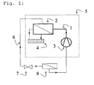
- a vehicle air conditioning system has a compressor 3, a heat exchanger 2 following in the direction of the circulation according to arrow 2, in which heat is withdrawn from the circulating refrigerant, and an inflow line 1 between compressor 3 and heat exchanger 2, which is also referred to as Discharge line in the context of the present invention.
- the heat exchanger 2 can be cooled by the cooling circuit of the vehicle 4 as described above.
- the heat exchanger 2 is releasably secured via a holder or directly on the engine, wherein the fastening means can be designed to be rigid or vibration-damped.
- the unit of engine and transmission (“Powertrain”) is shown by a dashed box 5.
- Powertrain The unit of engine and transmission
- the cooling circuit of the vehicle 4 shown here only schematically is not limited to the "powertrain" area alone.
- the line 6 Arranged downstream of the heat exchanger 2 are the line 6, an expansion element 7 following in the direction of circulation, and a further heat exchanger 8 (evaporator), through which the cooling of the interior air takes place, in that the coolant absorbs heat from outside in the latter.
- the subcritically working cooling processes usually referred to as capacitor first heat exchanger 2 is cooled by ambient air by the heat exchanger 2 flows as a wind or is blown by an additional blower.
- the heat receiving or air-cooling second Heat exchanger 8, which is commonly referred to as an evaporator, is arranged in the air distribution system of the motor vehicle or an associated bypass duct of this system, so that the air can be cooled if necessary.
- a buffer tank (accumulator) may be provided, in which a non-vaporized portion of the refrigerant (CO 2 ) settles, so that according to the operating condition of the system in this container, a stock amount of refrigerant is present.
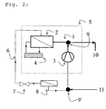
- Fig. 2 the arrangement shown in Fig. 1 is further developed by a split version of the Discharge line. Via an externally controlled switching valve 9, the Discharge line is connected to a line to an auxiliary heater 10, and via a connecting piece or switching valve 9 ', the suction line is connected to a line from the auxiliary heater 11.
Landscapes
- Physics & Mathematics (AREA)
- Thermal Sciences (AREA)
- Engineering & Computer Science (AREA)
- Mechanical Engineering (AREA)
- Air-Conditioning For Vehicles (AREA)
Claims (10)
- Véhicule automobile comprenant un dispositif de climatisation fonctionnant selon le procédé de vapeur froide de CO2, dans lequel on fait circuler du dioxyde de carbone (CO2) en guise de réfrigérant en circuit fermé à l'aide d'un compresseur (3) en direction d'un échangeur thermique (1, 2) avant de l'en ramener, et vers une unité moteur/transmission (5) présentant un circuit de refroidissement (4), caractérisé en ce que l'échangeur thermique (1,2) est solidaire de l'unité moteur/transmission (5) et peut être refroidi par le circuit de refroidissement (4) de celle-ci.
- Véhicule automobile selon la revendication 1, caractérisé en ce que l'échangeur thermique (1, 2) comprend un refroidisseur de gaz (2) et une conduite (1) susceptible d'être refroidie par le circuit de refroidissement (4).
- Véhicule automobile selon la revendication 2, caractérisé en ce que la conduite (1) reliée rigidement à l'unité moteur/transmission (5) conduit du compresseur (3) au refroidisseur de gaz (2).
- Véhicule automobile selon l'une des revendications 1 ou 3, caractérisé en ce que la conduite (1) est constituée sans élément flexible.
- Véhicule automobile selon l'une des revendications 1 à 4, caractérisé en ce que la conduite (1) est reliée au compresseur (3) à l'aide de raccords amovibles à vis.
- Véhicule automobile selon l'une des revendications 1 à 5, caractérisé en ce que la conduite (1) est reliée au refroidisseur de gaz (2) à l'aide de raccords amovibles à vis.
- Véhicule automobile selon l'une des revendications 1 à 5, caractérisé en ce que la conduite (1) est reliée rigidement au refroidisseur de gaz (2).
- Véhicule automobile selon l'une des revendications 1 à 7, caractérisé en ce que la conduite (1) est réalisée en aluminium, en ses alliages ou en acier.
- Véhicule automobile selon l'une des revendications 1 à 8, caractérisé en ce que la conduite (1) est réalisée en plusieurs parties, et en ce qu'est disposée à l'interface une valve de commutation commandée par l'électronique du dispositif de climatisation ou bien du moteur.
- Véhicule automobile selon la revendication 9, caractérisé en ce que la conduite (1) est reliée à un chauffage supplémentaire par l'intermédiaire de la valve de commutation commandée soit par l'électronique du dispositif de climatisation soit par l'électronique du moteur.
Priority Applications (1)
| Application Number | Priority Date | Filing Date | Title |
|---|---|---|---|
| PL05005824T PL1580052T3 (pl) | 2004-03-24 | 2005-03-17 | Urządzenie klimatyzacyjne do samochodu |
Applications Claiming Priority (2)
| Application Number | Priority Date | Filing Date | Title |
|---|---|---|---|
| DE102004014812 | 2004-03-24 | ||
| DE102004014812A DE102004014812B3 (de) | 2004-03-24 | 2004-03-24 | Fahrzeug-Klimmaanlage |
Publications (2)
| Publication Number | Publication Date |
|---|---|
| EP1580052A1 EP1580052A1 (fr) | 2005-09-28 |
| EP1580052B1 true EP1580052B1 (fr) | 2007-05-16 |
Family
ID=34745456
Family Applications (1)
| Application Number | Title | Priority Date | Filing Date |
|---|---|---|---|
| EP05005824A Expired - Lifetime EP1580052B1 (fr) | 2004-03-24 | 2005-03-17 | Dispositif de climatisation pour véhicule |
Country Status (4)
| Country | Link |
|---|---|
| EP (1) | EP1580052B1 (fr) |
| DE (2) | DE102004014812B3 (fr) |
| ES (1) | ES2285593T3 (fr) |
| PL (1) | PL1580052T3 (fr) |
Families Citing this family (2)
| Publication number | Priority date | Publication date | Assignee | Title |
|---|---|---|---|---|
| DE102005043709A1 (de) * | 2005-09-14 | 2007-03-15 | GM Global Technology Operations, Inc., Detroit | Fahrzeug-Klimaanlage |
| DE102006037443A1 (de) * | 2006-08-09 | 2008-02-14 | Behr Gmbh & Co. Kg | Kraftfahrzeug-Klimaanlagenanordnung |
Family Cites Families (6)
| Publication number | Priority date | Publication date | Assignee | Title |
|---|---|---|---|---|
| DE2204950A1 (de) * | 1972-02-03 | 1973-08-09 | Rudolf Hintze | Kuehlaggregat mit umlaufender kompressorkondensator-verdampfer-einheit und solekuehlung |
| US4036029A (en) * | 1975-06-25 | 1977-07-19 | Francis Philip L | Air conditioning unit for automobiles |
| NO890076D0 (no) * | 1989-01-09 | 1989-01-09 | Sinvent As | Luftkondisjonering. |
| CH689826A5 (de) * | 1995-05-10 | 1999-12-15 | Daimler Benz Ag | Fahrzeug-Klimaanlage. |
| JP2001289534A (ja) * | 2000-04-07 | 2001-10-19 | Toyota Autom Loom Works Ltd | 空調用ユニット |
| GB0012034D0 (en) * | 2000-05-19 | 2000-07-05 | Llanelli Radiators Ltd | Compressor/condenser unit |
-
2004
- 2004-03-24 DE DE102004014812A patent/DE102004014812B3/de not_active Revoked
-
2005
- 2005-03-17 DE DE502005000717T patent/DE502005000717D1/de not_active Expired - Fee Related
- 2005-03-17 PL PL05005824T patent/PL1580052T3/pl unknown
- 2005-03-17 ES ES05005824T patent/ES2285593T3/es not_active Expired - Lifetime
- 2005-03-17 EP EP05005824A patent/EP1580052B1/fr not_active Expired - Lifetime
Also Published As
| Publication number | Publication date |
|---|---|
| ES2285593T3 (es) | 2007-11-16 |
| DE102004014812B3 (de) | 2005-08-11 |
| EP1580052A1 (fr) | 2005-09-28 |
| PL1580052T3 (pl) | 2007-10-31 |
| DE502005000717D1 (de) | 2007-06-28 |
Similar Documents
| Publication | Publication Date | Title |
|---|---|---|
| DE102020124471A1 (de) | Montageverteiler eines gebündelten integrierten wärmepumpenmoduls | |
| DE112011104486B4 (de) | Wärmeaustauschsystem | |
| DE112011101957B4 (de) | Wärmepumpenkreislauf | |
| DE102017118425A1 (de) | Kreislaufsystem für ein Fahrzeug und Verfahren dazu | |
| DE102009060860A1 (de) | Klimatisierungssystem für ein Fahrzeug sowie Verfahren zum Temperieren | |
| DE112012005008T5 (de) | Wärmetauscher | |
| DE102017109313B4 (de) | Vorrichtung zur Wärmeübertragung für einen Kältemittelkreislauf eines Klimatisierungssystems eines Kraftfahrzeugs und Klimatisierungssystem mit der Vorrichtung | |
| EP1281545B1 (fr) | Dispositif d'échangeurs de chaleur refroidi par air et comprenant un refroidisseur de gaz CO2 | |
| DE112011102137T5 (de) | Wärmetauscher | |
| DE102009000767A1 (de) | Wärmeübertrager für ein Heiz-, Belüftungs- und Air-Conditioning-System | |
| EP1262344B1 (fr) | Echangeur de chaleur pour climatisation de véhicule | |
| DE102016100192A1 (de) | Vorrichtung zur Wärmeübertragung | |
| DE10306395A1 (de) | Klimaanlage mit mehreren Verdampfern für ein Kraftfahrzeug | |
| DE102015111393A1 (de) | Vorrichtung zur Wärmeübertragung | |
| EP1600314B1 (fr) | Arrangement et procédé d'operation dans un circuit de réfrigérant | |
| DE102004014812B3 (de) | Fahrzeug-Klimmaanlage | |
| DE102005027674A1 (de) | Klimaanlage für Fahrzeugverwendung | |
| WO2016206816A1 (fr) | Dispositif et procédé de dégivrage d'un échangeur de chaleur lors du fonctionnement d'évaporation d'une installation frigorifique et véhicule comprenant un dispositif de ce type | |
| DE102004003788A1 (de) | Klimaanlage | |
| WO2001069086A2 (fr) | Gestion thermique d'un vehicule motorise comportant un circuit de refroidissement et une climatisation | |
| DE102018221109B4 (de) | Klimatisierungseinrichtung für ein Kraftfahrzeug | |
| DE102017114993A1 (de) | Vorrichtung zur Wärmeübertragung und Verfahren zum Betreiben der Vorrichtung | |
| DE102005028510A1 (de) | Verstellbarer innerer Wärmeübertrager | |
| DE102004003787A1 (de) | Klimaanlage | |
| DE102005043709A1 (de) | Fahrzeug-Klimaanlage |
Legal Events
| Date | Code | Title | Description |
|---|---|---|---|
| PUAI | Public reference made under article 153(3) epc to a published international application that has entered the european phase |
Free format text: ORIGINAL CODE: 0009012 |
|
| AK | Designated contracting states |
Kind code of ref document: A1 Designated state(s): AT BE BG CH CY CZ DE DK EE ES FI FR GB GR HU IE IS IT LI LT LU MC NL PL PT RO SE SI SK TR |
|
| AX | Request for extension of the european patent |
Extension state: AL BA HR LV MK YU |
|
| 17P | Request for examination filed |
Effective date: 20060209 |
|
| AKX | Designation fees paid |
Designated state(s): AT BE BG CH CY CZ DE DK EE ES FI FR GB GR HU IE IS IT LI LT LU MC NL PL PT RO SE SI SK TR |
|
| GRAP | Despatch of communication of intention to grant a patent |
Free format text: ORIGINAL CODE: EPIDOSNIGR1 |
|
| GRAS | Grant fee paid |
Free format text: ORIGINAL CODE: EPIDOSNIGR3 |
|
| GRAA | (expected) grant |
Free format text: ORIGINAL CODE: 0009210 |
|
| RBV | Designated contracting states (corrected) |
Designated state(s): CZ DE ES FR GB IT PL |
|
| AK | Designated contracting states |
Kind code of ref document: B1 Designated state(s): CZ DE ES FR GB IT PL |
|
| REG | Reference to a national code |
Ref country code: GB Ref legal event code: FG4D Free format text: NOT ENGLISH |
|
| GBT | Gb: translation of ep patent filed (gb section 77(6)(a)/1977) |
Effective date: 20070516 |
|
| REF | Corresponds to: |
Ref document number: 502005000717 Country of ref document: DE Date of ref document: 20070628 Kind code of ref document: P |
|
| REG | Reference to a national code |
Ref country code: PL Ref legal event code: T3 |
|
| REG | Reference to a national code |
Ref country code: ES Ref legal event code: FG2A Ref document number: 2285593 Country of ref document: ES Kind code of ref document: T3 |
|
| PLBE | No opposition filed within time limit |
Free format text: ORIGINAL CODE: 0009261 |
|
| STAA | Information on the status of an ep patent application or granted ep patent |
Free format text: STATUS: NO OPPOSITION FILED WITHIN TIME LIMIT |
|
| 26N | No opposition filed |
Effective date: 20080219 |
|
| REG | Reference to a national code |
Ref country code: GB Ref legal event code: 732E Free format text: REGISTERED BETWEEN 20090305 AND 20090311 |
|
| PGFP | Annual fee paid to national office [announced via postgrant information from national office to epo] |
Ref country code: CZ Payment date: 20090225 Year of fee payment: 5 Ref country code: PL Payment date: 20090209 Year of fee payment: 5 |
|
| PGFP | Annual fee paid to national office [announced via postgrant information from national office to epo] |
Ref country code: GB Payment date: 20090311 Year of fee payment: 5 |
|
| PGFP | Annual fee paid to national office [announced via postgrant information from national office to epo] |
Ref country code: ES Payment date: 20090428 Year of fee payment: 5 |
|
| PGFP | Annual fee paid to national office [announced via postgrant information from national office to epo] |
Ref country code: DE Payment date: 20090313 Year of fee payment: 5 Ref country code: IT Payment date: 20090318 Year of fee payment: 5 |
|
| PGFP | Annual fee paid to national office [announced via postgrant information from national office to epo] |
Ref country code: FR Payment date: 20090316 Year of fee payment: 5 |
|
| REG | Reference to a national code |
Ref country code: GB Ref legal event code: 732E Free format text: REGISTERED BETWEEN 20091029 AND 20091104 |
|
| REG | Reference to a national code |
Ref country code: GB Ref legal event code: 732E Free format text: REGISTERED BETWEEN 20091105 AND 20091111 |
|
| GBPC | Gb: european patent ceased through non-payment of renewal fee |
Effective date: 20100317 |
|
| PG25 | Lapsed in a contracting state [announced via postgrant information from national office to epo] |
Ref country code: CZ Free format text: LAPSE BECAUSE OF NON-PAYMENT OF DUE FEES Effective date: 20100317 |
|
| REG | Reference to a national code |
Ref country code: FR Ref legal event code: ST Effective date: 20101130 |
|
| PG25 | Lapsed in a contracting state [announced via postgrant information from national office to epo] |
Ref country code: FR Free format text: LAPSE BECAUSE OF NON-PAYMENT OF DUE FEES Effective date: 20100331 |
|
| PG25 | Lapsed in a contracting state [announced via postgrant information from national office to epo] |
Ref country code: DE Free format text: LAPSE BECAUSE OF NON-PAYMENT OF DUE FEES Effective date: 20101001 |
|
| PG25 | Lapsed in a contracting state [announced via postgrant information from national office to epo] |
Ref country code: GB Free format text: LAPSE BECAUSE OF NON-PAYMENT OF DUE FEES Effective date: 20100317 Ref country code: IT Free format text: LAPSE BECAUSE OF NON-PAYMENT OF DUE FEES Effective date: 20100317 |
|
| REG | Reference to a national code |
Ref country code: ES Ref legal event code: FD2A Effective date: 20110415 |
|
| PG25 | Lapsed in a contracting state [announced via postgrant information from national office to epo] |
Ref country code: ES Free format text: LAPSE BECAUSE OF NON-PAYMENT OF DUE FEES Effective date: 20110404 |
|
| PG25 | Lapsed in a contracting state [announced via postgrant information from national office to epo] |
Ref country code: ES Free format text: LAPSE BECAUSE OF NON-PAYMENT OF DUE FEES Effective date: 20100318 |
|
| REG | Reference to a national code |
Ref country code: PL Ref legal event code: LAPE |
|
| PG25 | Lapsed in a contracting state [announced via postgrant information from national office to epo] |
Ref country code: PL Free format text: LAPSE BECAUSE OF NON-PAYMENT OF DUE FEES Effective date: 20100317 |