EP1579802A1 - Méthode et appareil de mesure du rythme cardiaque; support d'enregistrement d'un programme d'ordinateur permettant d'executer la méthode. - Google Patents
Méthode et appareil de mesure du rythme cardiaque; support d'enregistrement d'un programme d'ordinateur permettant d'executer la méthode. Download PDFInfo
- Publication number
- EP1579802A1 EP1579802A1 EP05251670A EP05251670A EP1579802A1 EP 1579802 A1 EP1579802 A1 EP 1579802A1 EP 05251670 A EP05251670 A EP 05251670A EP 05251670 A EP05251670 A EP 05251670A EP 1579802 A1 EP1579802 A1 EP 1579802A1
- Authority
- EP
- European Patent Office
- Prior art keywords
- signal
- reconfigured
- heart rate
- light signal
- circuit
- Prior art date
- Legal status (The legal status is an assumption and is not a legal conclusion. Google has not performed a legal analysis and makes no representation as to the accuracy of the status listed.)
- Withdrawn
Links
- 238000000034 method Methods 0.000 title claims abstract description 26
- 238000004590 computer program Methods 0.000 title abstract 2
- 230000003287 optical effect Effects 0.000 claims description 17
- 238000001914 filtration Methods 0.000 claims 1
- 230000017531 blood circulation Effects 0.000 abstract description 15
- 210000004204 blood vessel Anatomy 0.000 abstract description 10
- 238000005259 measurement Methods 0.000 abstract description 3
- 238000010586 diagram Methods 0.000 description 10
- 238000013500 data storage Methods 0.000 description 2
- 238000013186 photoplethysmography Methods 0.000 description 2
- 239000004065 semiconductor Substances 0.000 description 2
- QVGXLLKOCUKJST-UHFFFAOYSA-N atomic oxygen Chemical compound [O] QVGXLLKOCUKJST-UHFFFAOYSA-N 0.000 description 1
- 230000005540 biological transmission Effects 0.000 description 1
- 235000019577 caloric intake Nutrition 0.000 description 1
- 230000015556 catabolic process Effects 0.000 description 1
- 210000003467 cheek Anatomy 0.000 description 1
- 230000001276 controlling effect Effects 0.000 description 1
- 238000006731 degradation reaction Methods 0.000 description 1
- 230000002542 deteriorative effect Effects 0.000 description 1
- 210000000624 ear auricle Anatomy 0.000 description 1
- 210000003811 finger Anatomy 0.000 description 1
- 230000006870 function Effects 0.000 description 1
- 238000010606 normalization Methods 0.000 description 1
- 229910052760 oxygen Inorganic materials 0.000 description 1
- 239000001301 oxygen Substances 0.000 description 1
- 230000001105 regulatory effect Effects 0.000 description 1
- 230000004044 response Effects 0.000 description 1
- 210000000707 wrist Anatomy 0.000 description 1
Images


Classifications
-
- A—HUMAN NECESSITIES
- A61—MEDICAL OR VETERINARY SCIENCE; HYGIENE
- A61B—DIAGNOSIS; SURGERY; IDENTIFICATION
- A61B5/00—Measuring for diagnostic purposes; Identification of persons
- A61B5/02—Detecting, measuring or recording pulse, heart rate, blood pressure or blood flow; Combined pulse/heart-rate/blood pressure determination; Evaluating a cardiovascular condition not otherwise provided for, e.g. using combinations of techniques provided for in this group with electrocardiography or electroauscultation; Heart catheters for measuring blood pressure
- A61B5/024—Detecting, measuring or recording pulse rate or heart rate
- A61B5/02416—Detecting, measuring or recording pulse rate or heart rate using photoplethysmograph signals, e.g. generated by infrared radiation
-
- A—HUMAN NECESSITIES
- A61—MEDICAL OR VETERINARY SCIENCE; HYGIENE
- A61B—DIAGNOSIS; SURGERY; IDENTIFICATION
- A61B5/00—Measuring for diagnostic purposes; Identification of persons
- A61B5/02—Detecting, measuring or recording pulse, heart rate, blood pressure or blood flow; Combined pulse/heart-rate/blood pressure determination; Evaluating a cardiovascular condition not otherwise provided for, e.g. using combinations of techniques provided for in this group with electrocardiography or electroauscultation; Heart catheters for measuring blood pressure
Definitions
- the present invention relates to a method of and an apparatus for measuring heart rate, and more particularly, to a method of and an apparatus for measuring heart rate by measuring a blood flow.
- FIG. 1 shows an apparatus 20 for measuring heart rate by using blood flow.
- the apparatus 20 measures the blood flow, oxygen saturation, or heart rate in a human body part such as finger, wrist, cheek, or earlobe by using a photoplethysmography (PPG) sensor.
- PPG photoplethysmography
- the apparatus 20 comprises an optical transmitting circuit 30, an optical receiving circuit 40, and a processor 50.
- the optical transmitting circuit 30 When infrared or visible light output from the optical transmitting circuit 30 is reflected from a blood vessel of a finger 10, the optical receiving circuit 40 detects an amplitude of the reflected light from the blood vessel of the finger 10. The amplitude of the reflected light depends on the blood flow in the blood vessel.
- the processor 50 measures heart rate using the reflected light detected by the optical receiving circuit 40.
- measurement of the heart rate is often affected by a varying contact pressure between the finger 10 and the apparatus 20, a condition of a capillary vessel in the finger 10, or noise resulting from a movement of the finger 10, which results in deteriorating an accuracy in measurement.
- an apparatus for measuring heart rate comprising: an amplifying circuit receiving a light signal reflected or penetrated from a human body part and generating a multi-stage amplified signal composed of signals having a plurality of different gains according to a control signal; and a processor separating the multi-stage amplified signal provided from the amplifying circuit into a plurality of channel signals having corresponding gains, reconfiguring the light signal using a channel signal selected among the plurality of channel signals and calculating heart rate from the reconfigured light signal.
- the amplifying circuit may comprise: an amplifier amplifying a difference between a signal input to a first input terminal and a signal input to a second input terminal; a plurality of resistors having different resistances; and a multiplexer transmitting the received light signal to a corresponding resistor among the plurality of resistors according to the control signal output from the processor, and wherein each of the plurality of resistors is connected between the first input terminal and the multiplexer.
- the processor may comprise a first signal reconfiguring circuit separating the multi-stage amplified signal provided from the amplifying circuit into a plurality of channel signals having corresponding gains, dividing each of the plurality of channel signals into a unit of segments based on peak values of each of the plurality of channel signals, and generating a first reconfigured light signal including a channel signal selected among the plurality of channel signals with regard to each segment; a second signal reconfiguring circuit calculating a correlation coefficient from the first reconfigured signal and the basic pattern and generating a second reconfigured light signal using the correlation coefficient; and a heart rate calculating circuit comparing the second reconfigured signal with a reference correlation coefficient, and calculating the heart rate based on a signal obtained from the comparison result.
- a first signal reconfiguring circuit separating the multi-stage amplified signal provided from the amplifying circuit into a plurality of channel signals having corresponding gains, dividing each of the plurality of channel signals into a unit of segments based on peak values of each of the plurality of channel signals, and generating a
- the processor may comprise a signal reconfiguring circuit separating the multi-stage amplified signal provided from the amplifying circuit into a plurality of channel signals having corresponding gains, dividing each of the plurality of channel signals into a unit of segments based on peak values of each of the plurality of channel signals, and generating the reconfigured light signal including a channel signal selected among the plurality of channel signals with regard to each segment; and a heart rate calculating circuit comparing the reconfigured light signal with a reference correlation coefficient, and calculating the heart rate based on a signal obtained from the comparison result.
- an apparatus for measuring heart rate comprising: a detecting circuit detecting a light signal reflected or penetrated from a human body part; and a processor receiving the light signal from the detecting circuit, generating a reconfigured signal based on a correlation between the light signal and a basic pattern, and calculating heart rate from the reconfigured signal.
- the processor may comprise a signal reconfiguring circuit calculating a correlation coefficient from the light signal and the basic pattern and generating the reconfigured signal using the correlation coefficient; and a heart rate calculating circuit comparing the reconfigured signal with a reference correlation coefficient, and calculating the heart rate based on a signal obtained from the comparison result.
- a method of measuring heart rate comprising: receiving a light signal reflected or penetrated from a human body part; generating a multi-stage amplified signal by amplifying the light signal with a plurality of different gains according to a control signal; separating the multi-stage amplified signal into a plurality of channel signals having corresponding gains; reconfiguring the light signal using a channel signal selected among the plurality of channel signals; and calculating heart rate from the reconfigured light signal.
- the reconfiguring the light signal comprises: dividing each of the plurality of channel signals in a unit of segments, and generating a first reconfigured light signal including a channel signal selected among the plurality of channel signals with regard to each segment; and generating a second reconfigured light signal based on a correlation between the first reconfigured signal and a basic pattern.
- the reconfiguring the light signal comprises: dividing each of the plurality of channel signals in a unit of segments, and generating a reconfigured signal including a channel signal selected among the plurality of channel signals with regard to each segment.
- a program for executing the method of measuring heart rate from blood flow in the blood vessel of the body part may be stored on a computer-readable recording medium.
- the present invention thus provides a method of and an apparatus for measuring heart rate accurately by using blood flow, irrespective of a varying contact pressure between a human body part and the apparatus, a condition of a capillary vessel in the body part, or noise resulting from a movement of the body part.
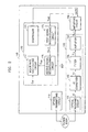
- FIG. 2 is a block diagram showing an apparatus 100 for measuring heart rate by using blood flow according to an embodiment of the present invention.
- the apparatus 100 can be implemented with semiconductor chips.
- the apparatus 100 comprises an optical transmitting circuit 110, a detecting circuit 130, an amplifying circuit 150, and a processor 170.
- the optical transmitting circuit 110 generates a light signal and outputs the light signal to a human body part.
- Examples of the light signal include infrared or visible light, but are not limited thereto.
- the detecting circuit 130 receives the infrared or visible light reflected or penetrated from the body part, particularly a blood vessel of the body part, filters the received light signal, amplifies the filtered light signal, and outputs the amplified light signal V out1 to an amplifying circuit 150.
- the detecting circuit 130 comprises an optical receiving circuit 131, an IN converter 133, a filter 135, and an amplifier 137.
- the optical receiving circuit 131 detects an amplitude of the infrared or visible light reflected or penetrated from the body part, and generates a current d i according to the detected amplitude.
- the amplitude of the infrared or visible light received by the optical receiving circuit 131 varies according to a thickness of a blood vessel of the body part. For instance, when the infrared or visible light output from the optical transmitting circuit 110 is input to the body part during expansion of the blood vessel of the body part, the blood vessel of the body part absorbs plenty of the infrared or visible light. Thus, the amplitude of the infrared or visible light reflected or penetrated from the body part is reduced, whereby the amount of current output from the optical receiving circuit 131 is small.
- the IN converter 133 receives the current d i from the optical receiving circuit 131 and generates a voltage c v corresponding to the current d i .
- the IN converter 133 acts as a current/voltage converter.
- the filter 135 is preferably implemented with a lowpass filter.
- the filter 135 receives the voltage C v from the IN converter 133, removes a high-frequency noise from the voltage c v , and outputs the result F cv .
- the amplifier 137 receives the voltage F cv output from the filter 135, amplifies the voltage F cv , and outputs the result V out1 .
- the amplifying circuit 150 generates a multi-stage amplified signal V out2 composed of a sum of signals having "n" different gains in response to a control signal CNTR output from a controller 171 of the processor 170.
- FIG. 3 shows a detailed circuit diagram of an amplifying circuit 150 in FIG. 2.
- the amplifying circuit 150 comprises an n-channel multiplexer 151, a plurality of resistors R 1 through R n , a comparator 155, and a resistor R 0 .
- the n-channel multiplexer 151 transmits a voltage V out1 output from the amplifier 137 to each of corresponding terminals A1 through An according to the control signal CNTR.
- Each of the resistors R 1 through R n is connected between each of the corresponding terminals A1 through An and a node 153.
- the resistances of the individual resistors R 1 through R n are preferably different from one another.
- a pair of each of the terminals A1 through An and each of the resistors R 1 through R n constitute a channel.
- the resistor R 0 is connected between an input terminal 153 and an output terminal of the comparator 155.
- the comparator 155 receives a bias voltage BIAS and a voltage of the node 153, amplifies a difference between the received voltages, and outputs the result V out2 .
- the comparator 155 and the resistor R 0 may be replaced with a single OP amp having a feedback resistor R 0 .
- FIG. 4 shows input and output waveforms of a first signal reconfiguring circuit 173 in FIG. 2.
- the output voltage V out2 of the amplifying circuit 150 is a signal obtained by superimposing a plurality of signals SA1 through SA8 having different gains.
- FIG. 4 shows an output signal V out2 of the amplifying circuit 150 composed of an eight-channel multiplexer 151. In other words, the number of resistors and terminals in FIG. 3 is 8, respectively.
- the output signal V out2 of the amplifying circuit 150 is separated into signals SA1 through SA8.
- SA1 represents the output signal V out2 of the amplifying circuit 150 when the voltage V out1 output from the amplifier 137 is input to the comparator 155 through the terminal A1 and the resistor R1.
- SAn (where “n” is 2 through 8) represents the output signal V out2 of the amplifying circuit 150 when the voltage V out1 output from the amplifier 137 is input to the comparator 155 through the terminal An (where “n” is 2 through 8) and the resistor R n (where "n” is 2 through 8).
- the processor 170 comprises a controller 171, a first signal reconfiguring circuit 173, a second signal reconfiguring circuit 175, and a heart rate calculating circuit 177.
- the processor 170 may be implemented with semiconductor chips.
- the processor 170 comprises a controller 171, a first signal reconfiguring circuit 173, and a heart rate calculating circuit 177. According to this, the output signal V out3 of the first signal reconfiguring circuit 173 is directly provided to the heart rate calculating circuit 177.
- the processor 170 comprises a controller 171, a second signal reconfiguring circuit 175, and a heart rate calculating circuit 177. According to this, the output signal V out1 of the amplifier 137 is directly provided to the second signal reconfiguring circuit 175.
- the controller 171 provides the control signal CNTR to the amplifying circuit 150 for controlling an operation of the n-channel multiplexer 151.
- the first signal reconfiguring circuit 173 receives the output signal V out2 of the amplifying circuit 150, stores the received signals, detects peak values of the stored output signal V out2 , which are peak values of heart rate signals, and divides adjacent peak values in a unit of segments.
- the first signal reconfiguring circuit 173 selects a single signal having an optimum amplitude in each segment (SG1 through SG6 in FIG. 4), and generates a first reconfigured signal V out3 including the selected signals.
- Each of the selected signals has an unsaturated highest peak value in each segment (SG1 through SG6 in FIG. 4).
- each of the signals selected in the individual segments is normalized by dividing by its gain, when the first reconfigured signal is generated.
- the first signal reconfiguring circuit 173 normalizes each of the signals selected in the segments SG1 through SG6, and outputs a reconfigured signal V out3 resulting from the normalization.
- the second signal reconfiguring circuit 175 receives the output signal V out3 from the first signal reconfiguring circuit 173 in FIG. 5, samples a signal 200 corresponding to one segment in the signal V out3 , normalizes the sampled signal 200, generates a basic pattern as shown in FIG. 6, and stores the basic pattern.
- the second signal reconfiguring circuit 175 may receive and store the basic pattern BSP as shown in FIG. 6 from outside.
- the second signal reconfiguring circuit 175 receives the basic pattern BSP and the output signal V out3 of the first signal reconfiguring circuit 173, estimates a correlation coefficient C between the basic pattern BSP and the signal of each segment in the output signal V out3 , and outputs a second, reconfigured signal V outc having the estimated correlation coefficient C in each segment to the heart rate calculating circuit 177.
- the correlation coefficient C may be estimated through Equation 2.
- X k(i) denotes a k(i)-th signal
- b i denotes an i-th basic pattern having a single cycle 0 through N
- ⁇ x and ⁇ b denote standard deviations of x and b, respectively
- x and b denote mean values of x and b, respectively
- P n denotes a n-th peak point
- P n+1 denotes a (n+1)-th peak point
- i denotes a natural number.
- each of the segments SG1 through SG6 is a sector between a central point of a n-th peak point and a (n+1)-th peak point and a central point of a (n+1)-th peak point and a (n+2)-th peak point.
- the sector of each of the segments according to the present invention is not limited to the sector as defined above.
- the first signal reconfiguring circuit 173 separates the output signal V out2 of the amplifying circuit 150 according to channels, detects a peak value of a signal in each of the channels, allots a sector between neighboring peak values to a segment, selects signals allotted to each segment according to a predetermined standard, reconfigures the selected signals, and outputs the result V out3 .
- the predetermined standard is a standard for obtaining a signal having an unsaturated highest peak value.
- the heart rate calculating circuit 177 receives the second reconfigured signal V outc having the correlation coefficient C and a reference correlation coefficient C ref , compares the correlation coefficient C and the reference correlation coefficient C ref , and calculates the heart rate from a signal having the correlation coefficient C larger than the reference correlation coefficient C ref , according to the comparison result.
- the reference correlation coefficient C ref may be input from outside the apparatus 100, or be already stored in a memory of the heart rate calculating circuit 177. For instance, when the correlation coefficient C has a range of 0 through 1, the correlation coefficient C may be close to 1 for a normal signal, and the correlation coefficient C may be close to 0 for a signal with noise. However, a range of the correlation coefficient C may be diversely set.
- FIG. 7 shows an output waveform of a first signal reconfiguring circuit 173 including noise.
- FIG. 8 shows a correlation coefficient of the output waveform in FIG. 7.
- the heart rate calculating circuit 177 counts only a signal having the correlation coefficient C greater than the reference correlation coefficient C ref among the output signal V outc of the second signal reconfiguring circuit 175, but does not count different signals regarded as noise. Therefore, even though noise is included in the output signal V out3 of the first signal reconfiguring circuit 173, the heart rate calculating circuit 177 counts the heart rate excluding the noise by using the correlation, and outputs the result to a display (not shown). Therefore, a method of measuring the heart rate by using the blood flow in a blood vessel of the body part can be used by the apparatus 100.
- the method may be implemented as a software program stored on a computer-readable recording medium.
- the computer-readable recording medium is any data storage device that can store data which can be thereafter read by a computer system. Examples of the computer-readable recording medium include read-only memory (ROM), random-access memory (RAM), CD-ROMs, magnetic tapes, floppy disks, optical data storage devices, and carrier waves (such as data transmission through the Internet).
- the computer-readable recording medium can also be distributed over network-coupled computer systems so that the computer-readable code is stored and executed in a distributed fashion.
- functional programs, codes, and code segments for accomplishing the present invention can be easily construed by programmers skilled in the art to which the present invention pertains.
- the method and apparatus according to the present invention can be used in a portable heart rate measuring instrument capable of measuring heart rate by using blood flow, an MP3 player having a function of measuring the amount of exercise, a stress measuring instrument, a calorie consumption measuring instrument or the like.
- the method and apparatus for measuring heart rate by using blood flow does not require an additional operation of regulating a gain, it is possible to reduce the time for measuring the heart rate.
- the method and apparatus for measuring heart rate by using blood flow is resistive to noise resulting from a movement of a body part by comparing an optimum signal pattern with a correlation coefficient.
- the apparatus and method for measuring heart rate by using blood flow can prevent performance degradation resulting from a varying contact pressure between the body part and the apparatus.
Applications Claiming Priority (2)
| Application Number | Priority Date | Filing Date | Title |
|---|---|---|---|
| KR1020040019626A KR100846488B1 (ko) | 2004-03-23 | 2004-03-23 | 심박수 검출 장치, 심박수 검출 방법 및 그 기록매체 |
| KR2004019626 | 2004-03-23 |
Publications (1)
| Publication Number | Publication Date |
|---|---|
| EP1579802A1 true EP1579802A1 (fr) | 2005-09-28 |
Family
ID=34858874
Family Applications (1)
| Application Number | Title | Priority Date | Filing Date |
|---|---|---|---|
| EP05251670A Withdrawn EP1579802A1 (fr) | 2004-03-23 | 2005-03-18 | Méthode et appareil de mesure du rythme cardiaque; support d'enregistrement d'un programme d'ordinateur permettant d'executer la méthode. |
Country Status (4)
| Country | Link |
|---|---|
| US (1) | US9649038B2 (fr) |
| EP (1) | EP1579802A1 (fr) |
| JP (1) | JP2005270661A (fr) |
| KR (1) | KR100846488B1 (fr) |
Cited By (2)
| Publication number | Priority date | Publication date | Assignee | Title |
|---|---|---|---|---|
| WO2018202606A1 (fr) | 2017-05-04 | 2018-11-08 | Bayer Aktiengesellschaft | Identification de troubles du rythme cardiaque |
| WO2019141551A1 (fr) | 2018-01-16 | 2019-07-25 | Bayer Aktiengesellschaft | Accompagnement de patients souffrant d'une insuffisance cardiaque |
Families Citing this family (8)
| Publication number | Priority date | Publication date | Assignee | Title |
|---|---|---|---|---|
| KR101019764B1 (ko) * | 2008-09-22 | 2011-03-04 | 건양대학교산학협력단 | 진동 및 잡음이 포함된 피피지 신호에서 정확한 심박을 측정하기 위한 피피지 기반의 심박 검출 방법 |
| US10687742B2 (en) | 2015-06-12 | 2020-06-23 | ChroniSense Medical Ltd. | Using invariant factors for pulse oximetry |
| US11160461B2 (en) | 2015-06-12 | 2021-11-02 | ChroniSense Medical Ltd. | Blood pressure measurement using a wearable device |
| US11160459B2 (en) * | 2015-06-12 | 2021-11-02 | ChroniSense Medical Ltd. | Monitoring health status of people suffering from chronic diseases |
| US11464457B2 (en) | 2015-06-12 | 2022-10-11 | ChroniSense Medical Ltd. | Determining an early warning score based on wearable device measurements |
| US10952638B2 (en) | 2015-06-12 | 2021-03-23 | ChroniSense Medical Ltd. | System and method for monitoring respiratory rate and oxygen saturation |
| US11712190B2 (en) | 2015-06-12 | 2023-08-01 | ChroniSense Medical Ltd. | Wearable device electrocardiogram |
| US11000235B2 (en) | 2016-03-14 | 2021-05-11 | ChroniSense Medical Ltd. | Monitoring procedure for early warning of cardiac episodes |
Citations (4)
| Publication number | Priority date | Publication date | Assignee | Title |
|---|---|---|---|---|
| EP0554208A2 (fr) * | 1992-01-14 | 1993-08-04 | Incontrol, Inc. | Appareil implantable de surveillance cardiaque |
| US20020045806A1 (en) * | 1995-08-07 | 2002-04-18 | Baker Clark R. | Method and apparatus for estimating physiological parameters using model-based adaptive filtering |
| EP1354553A1 (fr) * | 2002-04-15 | 2003-10-22 | Samsung Electronics Co., Ltd. | Dispositif et procédé pour la détection des battements de coeur à l'aide de PPG |
| EP1393673A1 (fr) * | 2002-08-30 | 2004-03-03 | Pioneer Corporation | Système, méthode, programme et support de stockage pour la mesure de la fréquence cardiaque |
Family Cites Families (14)
| Publication number | Priority date | Publication date | Assignee | Title |
|---|---|---|---|---|
| US5012411A (en) * | 1985-07-23 | 1991-04-30 | Charles J. Policastro | Apparatus for monitoring, storing and transmitting detected physiological information |
| JPH04138342A (ja) * | 1990-09-29 | 1992-05-12 | Shimadzu Corp | 光診断装置 |
| US5368026A (en) * | 1993-03-26 | 1994-11-29 | Nellcor Incorporated | Oximeter with motion detection for alarm modification |
| US6018673A (en) * | 1996-10-10 | 2000-01-25 | Nellcor Puritan Bennett Incorporated | Motion compatible sensor for non-invasive optical blood analysis |
| US5830137A (en) * | 1996-11-18 | 1998-11-03 | University Of South Florida | Green light pulse oximeter |
| JP3567319B2 (ja) | 1997-12-26 | 2004-09-22 | 日本光電工業株式会社 | パルスオキシメータ用プローブ |
| KR20000075056A (ko) | 1999-05-28 | 2000-12-15 | 임현수 | 산소포화도 및 혈류량 광센서 시스템 |
| US6360113B1 (en) * | 1999-12-17 | 2002-03-19 | Datex-Ohmeda, Inc. | Photoplethysmographic instrument |
| US7171251B2 (en) * | 2000-02-01 | 2007-01-30 | Spo Medical Equipment Ltd. | Physiological stress detector device and system |
| US6385821B1 (en) * | 2000-02-17 | 2002-05-14 | Udt Sensors, Inc. | Apparatus for securing an oximeter probe to a patient |
| JP2002238866A (ja) | 2001-02-22 | 2002-08-27 | Mitsubishi Electric Corp | 脈波計測装置 |
| KR20020069866A (ko) * | 2001-02-28 | 2002-09-05 | (주)라이픈콘트롤 | 이동통신 단말기용 생체 신호감지기 |
| KR20040043981A (ko) * | 2002-11-20 | 2004-05-27 | 안재목 | 심박수 레코더 및 에치알브이분석에 의한 건강 모니터링시스템 |
| JP3760920B2 (ja) * | 2003-02-28 | 2006-03-29 | 株式会社デンソー | センサ |
-
2004
- 2004-03-23 KR KR1020040019626A patent/KR100846488B1/ko active IP Right Grant
-
2005
- 2005-03-18 EP EP05251670A patent/EP1579802A1/fr not_active Withdrawn
- 2005-03-23 JP JP2005083067A patent/JP2005270661A/ja not_active Withdrawn
- 2005-03-23 US US11/086,412 patent/US9649038B2/en active Active
Patent Citations (4)
| Publication number | Priority date | Publication date | Assignee | Title |
|---|---|---|---|---|
| EP0554208A2 (fr) * | 1992-01-14 | 1993-08-04 | Incontrol, Inc. | Appareil implantable de surveillance cardiaque |
| US20020045806A1 (en) * | 1995-08-07 | 2002-04-18 | Baker Clark R. | Method and apparatus for estimating physiological parameters using model-based adaptive filtering |
| EP1354553A1 (fr) * | 2002-04-15 | 2003-10-22 | Samsung Electronics Co., Ltd. | Dispositif et procédé pour la détection des battements de coeur à l'aide de PPG |
| EP1393673A1 (fr) * | 2002-08-30 | 2004-03-03 | Pioneer Corporation | Système, méthode, programme et support de stockage pour la mesure de la fréquence cardiaque |
Cited By (2)
| Publication number | Priority date | Publication date | Assignee | Title |
|---|---|---|---|---|
| WO2018202606A1 (fr) | 2017-05-04 | 2018-11-08 | Bayer Aktiengesellschaft | Identification de troubles du rythme cardiaque |
| WO2019141551A1 (fr) | 2018-01-16 | 2019-07-25 | Bayer Aktiengesellschaft | Accompagnement de patients souffrant d'une insuffisance cardiaque |
Also Published As
| Publication number | Publication date |
|---|---|
| US20050215913A1 (en) | 2005-09-29 |
| KR100846488B1 (ko) | 2008-07-17 |
| KR20050094502A (ko) | 2005-09-28 |
| JP2005270661A (ja) | 2005-10-06 |
| US9649038B2 (en) | 2017-05-16 |
Similar Documents
| Publication | Publication Date | Title |
|---|---|---|
| EP1579802A1 (fr) | Méthode et appareil de mesure du rythme cardiaque; support d'enregistrement d'un programme d'ordinateur permettant d'executer la méthode. | |
| US4319241A (en) | Telemetering system for operating room and the like | |
| US4356486A (en) | Telemetering system for operating room and the like | |
| US20150216427A1 (en) | System for processing exercise-related data | |
| US9877661B2 (en) | Aural heart monitoring apparatus and method | |
| EP3127478B1 (fr) | Dispositifs et procédés pour des mesures photopléthysmographiques | |
| CA2260928C (fr) | Oxymetre convertissant un signal direct en signal numerique | |
| JPH0758565A (ja) | 自動音量制御装置 | |
| US7930886B2 (en) | Bio signal measuring apparatus and method | |
| JP4760342B2 (ja) | 生体状態検出装置 | |
| JPH06174A (ja) | パルスオキシメータ | |
| US20230301526A1 (en) | Apparatus and method for estimating blood pressure | |
| JPS6133578B2 (fr) | ||
| US6282439B1 (en) | Method of measuring vital function and measuring device | |
| US8155327B2 (en) | Tone detector and method used in a robot for detecting a tone | |
| JP5327194B2 (ja) | 生体状態検出装置 | |
| JPH04655B2 (fr) | ||
| JP5742884B2 (ja) | 生体状態検出装置 | |
| CN109068992B (zh) | 睡眠信号调节装置和方法 | |
| EP1464275B1 (fr) | Dispositif de mesure de l'onde pulsatile comprenant une unité de correction | |
| US4635645A (en) | Electronic sphygmomanometer | |
| US10159417B2 (en) | Apparatus and method for measuring pulse wave | |
| US6748092B1 (en) | Hearing aid with improved percentile estimator | |
| EP3539466B1 (fr) | Snr de signaux intracardiaques | |
| WO2007094427A1 (fr) | Lecteur de contenu |
Legal Events
| Date | Code | Title | Description |
|---|---|---|---|
| PUAI | Public reference made under article 153(3) epc to a published international application that has entered the european phase |
Free format text: ORIGINAL CODE: 0009012 |
|
| AK | Designated contracting states |
Kind code of ref document: A1 Designated state(s): AT BE BG CH CY CZ DE DK EE ES FI FR GB GR HU IE IS IT LI LT LU MC NL PL PT RO SE SI SK TR |
|
| AX | Request for extension of the european patent |
Extension state: AL BA HR LV MK YU |
|
| 17P | Request for examination filed |
Effective date: 20060215 |
|
| AKX | Designation fees paid |
Designated state(s): DE FR GB |
|
| 17Q | First examination report despatched |
Effective date: 20090219 |
|
| STAA | Information on the status of an ep patent application or granted ep patent |
Free format text: STATUS: THE APPLICATION IS DEEMED TO BE WITHDRAWN |
|
| 18D | Application deemed to be withdrawn |
Effective date: 20090630 |