EP1579197B1 - Verfahren zur optischen charakterisierung von materialen ohne verwendung eines physikalischen modells - Google Patents
Verfahren zur optischen charakterisierung von materialen ohne verwendung eines physikalischen modells Download PDFInfo
- Publication number
- EP1579197B1 EP1579197B1 EP03810019.4A EP03810019A EP1579197B1 EP 1579197 B1 EP1579197 B1 EP 1579197B1 EP 03810019 A EP03810019 A EP 03810019A EP 1579197 B1 EP1579197 B1 EP 1579197B1
- Authority
- EP
- European Patent Office
- Prior art keywords
- initial
- interval
- equal
- interpolation
- choose
- Prior art date
- Legal status (The legal status is an assumption and is not a legal conclusion. Google has not performed a legal analysis and makes no representation as to the accuracy of the status listed.)
- Expired - Lifetime
Links
- 238000000034 method Methods 0.000 title claims description 80
- 239000000463 material Substances 0.000 title claims description 67
- 238000012512 characterization method Methods 0.000 title claims description 18
- 230000003287 optical effect Effects 0.000 title claims description 15
- 238000001228 spectrum Methods 0.000 claims description 74
- 238000005259 measurement Methods 0.000 claims description 52
- 230000008033 biological extinction Effects 0.000 claims description 29
- 238000004364 calculation method Methods 0.000 claims description 13
- 238000002310 reflectometry Methods 0.000 claims description 13
- 238000000572 ellipsometry Methods 0.000 claims description 11
- 239000000758 substrate Substances 0.000 claims description 10
- 230000002745 absorbent Effects 0.000 claims description 2
- 239000002250 absorbent Substances 0.000 claims description 2
- 239000010410 layer Substances 0.000 description 57
- 230000000977 initiatory effect Effects 0.000 description 12
- 238000004422 calculation algorithm Methods 0.000 description 7
- 238000010521 absorption reaction Methods 0.000 description 6
- 238000005293 physical law Methods 0.000 description 6
- 230000003595 spectral effect Effects 0.000 description 6
- 230000010287 polarization Effects 0.000 description 5
- 238000005457 optimization Methods 0.000 description 4
- 238000005070 sampling Methods 0.000 description 4
- 238000010845 search algorithm Methods 0.000 description 4
- 230000000295 complement effect Effects 0.000 description 3
- 229920000535 Tan II Polymers 0.000 description 2
- 238000004458 analytical method Methods 0.000 description 2
- 230000003416 augmentation Effects 0.000 description 2
- 238000004377 microelectronic Methods 0.000 description 2
- 235000019592 roughness Nutrition 0.000 description 2
- 241000135309 Processus Species 0.000 description 1
- XUIMIQQOPSSXEZ-UHFFFAOYSA-N Silicon Chemical compound [Si] XUIMIQQOPSSXEZ-UHFFFAOYSA-N 0.000 description 1
- 241000607057 Stenodus Species 0.000 description 1
- 238000007796 conventional method Methods 0.000 description 1
- 230000002950 deficient Effects 0.000 description 1
- 238000000280 densification Methods 0.000 description 1
- 239000003814 drug Substances 0.000 description 1
- 238000005530 etching Methods 0.000 description 1
- 238000005286 illumination Methods 0.000 description 1
- 238000000691 measurement method Methods 0.000 description 1
- 230000003647 oxidation Effects 0.000 description 1
- 238000007254 oxidation reaction Methods 0.000 description 1
- 229920002120 photoresistant polymer Polymers 0.000 description 1
- 238000012545 processing Methods 0.000 description 1
- 238000011160 research Methods 0.000 description 1
- 229920005989 resin Polymers 0.000 description 1
- 239000011347 resin Substances 0.000 description 1
- 229910052710 silicon Inorganic materials 0.000 description 1
- 239000010703 silicon Substances 0.000 description 1
- 238000002922 simulated annealing Methods 0.000 description 1
- 239000002356 single layer Substances 0.000 description 1
- 238000000391 spectroscopic ellipsometry Methods 0.000 description 1
- 239000000126 substance Substances 0.000 description 1
- 238000012360 testing method Methods 0.000 description 1
- 238000000427 thin-film deposition Methods 0.000 description 1
Images


Classifications
-
- G—PHYSICS
- G01—MEASURING; TESTING
- G01N—INVESTIGATING OR ANALYSING MATERIALS BY DETERMINING THEIR CHEMICAL OR PHYSICAL PROPERTIES
- G01N21/00—Investigating or analysing materials by the use of optical means, i.e. using sub-millimetre waves, infrared, visible or ultraviolet light
- G01N21/17—Systems in which incident light is modified in accordance with the properties of the material investigated
- G01N21/21—Polarisation-affecting properties
- G01N21/211—Ellipsometry
-
- G—PHYSICS
- G01—MEASURING; TESTING
- G01N—INVESTIGATING OR ANALYSING MATERIALS BY DETERMINING THEIR CHEMICAL OR PHYSICAL PROPERTIES
- G01N21/00—Investigating or analysing materials by the use of optical means, i.e. using sub-millimetre waves, infrared, visible or ultraviolet light
- G01N21/17—Systems in which incident light is modified in accordance with the properties of the material investigated
- G01N21/21—Polarisation-affecting properties
- G01N21/211—Ellipsometry
- G01N2021/213—Spectrometric ellipsometry
Definitions
- the present invention relates to a method for optical characterization of materials.
- optical characterization of materials is useful for the chemical analysis of these materials (in particular study of absorption bands, densification properties and oxidation properties), in the fields of microelectronics, sensors, biology, of medicine), or for the analysis of the deposit thicknesses of these materials.
- the characterization of the optical properties of a material is also useful when the material is subsequently structured (to form, for example, etchings or roughnesses) and that the optical diffraction properties of the obtained structure must be calculated (see document [2]).
- the angle of incidence of the illumination light may be non-zero.
- the reflection coefficient can be measured for several angles of incidence ⁇ .
- R ( ⁇ , ⁇ , p) the reflectometry spectrum, where p is the polarization of the incident beam and ⁇ the wavelength of the latter.
- the angle ⁇ is zero and the polarization p indeterminate. In the case where ⁇ is not zero, it is necessary to know this polarization p. In general, the latter is of type (S) where (P).
- the measured quantities are then the real and imaginary parts of the ratio of the coefficient polarization reflection (P) at the polarization reflection coefficient (S).
- the spectra S i , i ⁇ [1, 2] are measured over a range of wavelengths [ ⁇ m , ⁇ M ].
- the angle of incidence can be any.
- Several spectra can be measured at different angles of incidence to obtain a richer spectrum.
- s ( ⁇ , ⁇ ) ⁇ S 1 ( ⁇ , ⁇ ), S 2 ( ⁇ , ⁇ ) ⁇ the ellipsometric spectrum.
- goniometric measurements may be added to the measurements used for the characterization, in order to determine the thickness of the various layers, for one or more wavelengths. These measurements are not sufficient in themselves since we want to determine the complex refractive index over a spectral range from ⁇ m to ⁇ M.
- ⁇ a set of spectrophotometric and / or ellipsometric spectra (s) (and possibly goniometric for some wavelengths).
- Er ( ⁇ (1) , ⁇ (2) ) denotes an error function (for example, the mean squared difference) between two spectra ⁇ (1) and ⁇ (2) .
- Weighting factors can be applied to the integral so that the error function can account for variations in the measurement accuracy of the spectra.
- the deposited material is well known, that is to say that the complex refractive index of this material is well known at the wavelengths of the light used for the characterization.
- the laws followed by the complex refractive index are either tabulated or approximated by known physical laws such as, for example, the Cauchy model, the Sellmeier model (see document [3]), the Forouhi laws ( see the document [4]), and the laws laws of harmonic oscillators (see the document [5]). These laws are defined by a finite number of parameters.
- a search algorithm is used to find the thickness that minimizes the error between the measurement ⁇ and the theoretical response ⁇ given the modeled index.
- the search algorithm may be, for example, the Simplex method, the Tabou search, the Levendt-Marquart method or the simulated annealing method (see Chapter 10 of document [6]).
- the coefficients a i are integrated in the adjustment procedure of ⁇ and ⁇ .
- the search for the coefficients a i constitutes a method of characterization of the refractive index.
- the second application is the characterization of materials.
- the process used remains the same, except that the material is not well known. It is precisely the complex refractive index function closest to reality that is targeted.
- PAP point-to-point method
- a search algorithm tries to find the thickness, the index n ( ⁇ i ) and the extinction coefficient k ( ⁇ i ) which minimize the error between the measure ⁇ ( ⁇ i ) and the theoretical answer ⁇ ( ⁇ i , n ( ⁇ i ), k ( ⁇ i ), ⁇ ).
- Such a method poses a problem because the various points ( ⁇ i , ⁇ , n ( ⁇ i ), k ( ⁇ i )) are not necessarily physically compatible with each other: for example, the thickness found may vary according to the wavelength and the law followed by the complex refractive index, more simply called the index law, may have discontinuities.
- the present invention aims to overcome the above disadvantages.
- the method of the invention makes it possible to characterize a material without using a physical model, that is to say without using a physical law followed by the complex refractive index of the studied material. It is therefore particularly useful when such a law is not known.
- node method This process constitutes an alternative to the known characterization methods mentioned above. It can be called “node method” because it uses “nodes” that is to say points of coordinates ( ⁇ i , not i * ), or not i * is the value taken by the complex refractive index at the wavelength ⁇ i and i takes a limited number of values (integers).
- the invention is useful for characterizing a spectrum or part of the spectrum.
- Each interpolation law can be chosen from linear interpolation laws, cubic interpolation laws, polynomial interpolation laws and interpolation laws, for example of the "spline" function type.
- the spectrum is sampled uniformly in ⁇ ( ⁇ ), that is to say that the initial values of the function ⁇ (see step 2) mentioned above) are uniformly distributed in the interval A, the distribution of the nodes thus being homogeneous.
- ⁇ ( ⁇ ) can be chosen from ⁇ , 1 / ⁇ , and hc / ⁇ or any other function of ⁇ , where h is the Planck constant and c is the speed of light in vacuum .
- the error is measured on an interval of interest C which is included in the interval B or equal to this interval B.
- the M variable parameters may be the real parts of the refractive indices at points ⁇ i , i ranging from 1 to m, or the imaginary parts of these refractive indices, or these M variable parameters may be constituted by the thickness of the material of which we look for the refractive index.
- n is at least 2; according to a second particular embodiment, m is equal to 1 and initial initial refractive indices are chosen.
- the material is non-absorbent and the number M is equal to m, the extinction coefficient of the material being taken equal to 0; according to another particular embodiment, M is at least equal to 2 m, an interpolation law is also chosen for the extinction coefficient of the material, for each initial wavelength ⁇ i , 1 ⁇ i ⁇ m in addition, an initial extinction coefficient k i is chosen, the initial wavelengths being furthermore chosen so as to be able to determine by interpolation the extinction coefficient for any wavelength of the interval ⁇ min, ⁇ max], and in the optimization process, the error is minimized by further varying the values of the extinction coefficients at the initial wavelengths and the added wavelengths are furthermore placed so as to represent at best the spectrum of the extinction coefficient of the material.
- m may be 1 and equal initial refractive indices and initial initial extinction coefficients may be selected.
- the layer of material may be thin, that is to say have a thickness less than the coherence length of the light used for the measurements, it is possible to choose a additional initial parameter, namely an initial layer thickness, and in the optimization process the error can be minimized by further varying the value of the layer thickness; alternatively, the material layer may be thick, i.e. not be thin, and M may be at most 2 m; in another variant, the thickness of the layer of material can be known with sufficient accuracy and M is at most equal to 2 m.
- the distribution of the nodes can be homogeneous.
- the invention provides an alternative to the conventional methods mentioned above. It makes it possible to combine the coherence of a layer model (corresponding to a continuous index law and to constant physical thicknesses), to the generality concerning the index law to be found (as in the PAP method). In addition, the resolution is limited only by the resolution of the measured spectrum.
- This interpolation law makes it possible to calculate, from the nodes, the refractive indices and the extinction coefficients for the wavelengths located between the nodes.
- the refractive index is characterized by a set of values for wavelengths ⁇ 1 ... ⁇ m
- one can use a linear interpolation between two wavelengths ⁇ i and ⁇ i + 1 for calculate the index n at the wavelength ⁇ (see the document [6] chapter 3): not ⁇ ⁇ i + 1 - ⁇ not ⁇ i + ⁇ - ⁇ i not ⁇ i + 1 ⁇ i + 1 - ⁇ i with ⁇ i ⁇ ⁇ i + 1
- a layer model is therefore characterized by a thickness ⁇ and a family of nodes.
- the measurements ⁇ consist of a reflectometric measurement R ( ⁇ ) and an ellipsometric measurement S 1.2 ( ⁇ , ⁇ ) where ⁇ is the angle of incidence of the light beam that is sent on the layer to be studied when measuring ellipsometry.
- This layer is a thin layer so that the thickness of this layer is also a variable of the problem.
- the loop thus defined is stopped when the precision on each of the spectra n ( ⁇ ) and k ( ⁇ ) and on the thickness ⁇ is considered sufficient (satisfactory adjustment of ⁇ and ⁇ ).
- the figure 1 shows schematically the studied layer 2, formed on a substrate 4.
- electronic processing means 12 comprising a computer and making it possible to characterize n ( ⁇ ), k ( ⁇ ) and ⁇ as a function of the information provided by the spectrometer 10 and in accordance with the method of the invention.
- These means 12 are provided with display means 14 which make it possible, in particular, to display the curve of the variations of n as a function of ⁇ and the curve of the variations of k as a function of ⁇ .
- the method of this example comprises first an initialization step.
- the algorithm starts with a reduced number of nodes, more precisely at least one node.
- Node positions are chosen so that, from this family of nodes, the whole spectrum can be deduced by interpolation.
- the layer model is therefore 3 or more parameters, since the thickness is also a variable to be determined.
- the index table over the entire spectrum is deduced from the nodes by interpolation.
- the thickness of the layers is of the order of magnitude of the wavelength (thin layers). But when the thickness of the layer is greater than the coherence length of the light source, the thickness intervenes almost no longer in the calculation of the response of the layer, and is no longer a variable of the problem.
- the reflection coefficient of such a layer is no longer a function of thickness of the layer but only of the refractive index thereof, the coherence length of the incident light beam being less than the thickness of the layer.
- the coherence length of the incident beam is determined by the roughness of the layers.
- the starting thickness is, for its part, chosen as close as possible to the actual thickness.
- the values of the refractive index and extinction coefficient on the nodes and the value of the thickness are then optimally determined.
- the spectra ⁇ ( ⁇ ) are calculated using the layer model used, resulting from the choice of nodes, the interpolation law and the thickness of the layer.
- the physical model used for the calculation of ⁇ is of course a function of the measurement method used, that is to say in particular the angle of incidence of the light, the spectrum used and the model of thin layers or thick layers if appropriate (see for example stacked layer models in document [3]).
- the spectra ⁇ being constituted by a set of measurements of various natures (for example ellipsometric and reflectometric measurements), one uses for the reflectometry measurements (respectively of ellipsometry) a method of calculation of reflectometry (respectively of ellipsometry).
- the layer model (refractive index, extinction coefficient and thickness) that best corresponds to the actual layer is obtained.
- the nodes added are positioned so as to best represent the spectra n ( ⁇ ) and k ( ⁇ ). For example, these additional nodes are placed where the difference between ⁇ and ⁇ is maximum or at the places in which the nodes are the most spaced. And we go back to phase 2 as long as the precision on each of the spectra n ( ⁇ ) and k ( ⁇ ) and on the thickness ⁇ is not sufficient, that is to say is not equal to a predefined precision.
- new nodes are inserted between two nodes of the set of previously selected nodes, these new nodes being distributed homogeneously over the spectrum.
- Fictitious measurements (ellipsometric measurements, reflectometry measurements) are calculated and then noised so as to introduce a defective apparatus.
- This index law is typical of photosensitive resins (in the spectral range from 300 nm to 800 nm).
- the figure 2 allows to compare the refractive index corresponding to the fictitious material which perfectly follows a Cauchy law (curve I) with the index of refraction which we find by the method of the nodes (curve II), using 6 knots (represented by circles on the figure 2 ).
- Curve I the refractive index corresponding to the fictitious material which perfectly follows a Cauchy law
- curve II the index of refraction which we find by the method of the nodes
- 6 knots represented by circles on the figure 2 .
- a ⁇ composed of an ellipsometric measurement ⁇ S 1 ( ⁇ ), S 2 ( ⁇ ) ⁇ at 70 ° and a reflectometric measurement R ( ⁇ ).
- the node method is applied to a set of ellipsometric measurements made between 250nm and 800nm, at 75 °, 70 °, 60 ° and 45 °, with in addition a reflectometric measurement.
- the actual thickness of the material being 200 nm, we find a thickness of 200.25 nm with the method of knots.
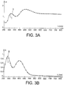
- the adjustment on the index law considered in this second example is very good, as shown by the Figures 3A and 3B .
- FIGS 3A and 3B illustrate respectively the reconstructions of the curves n ( ⁇ ) and k ( ⁇ ) of the material using the method of the nodes.
- the reconstruction is performed using four ellipsometric spectra and a reflectometric spectrum.
- the actual absorption peaks are very well represented by the curve obtained by cubic interpolation between the nodes (represented by circles on the Figures 3A and 3B ).
- the curve I corresponds to a refractive index n which follows perfectly the chosen law (respectively to a refractive index n found by the method of the nodes).
- the curve I corresponds to an extinction coefficient k which follows perfectly the chosen law (respectively to an extinction coefficient k found by the method of the nodes).
- the error minimization operation Er ( ⁇ , ⁇ ) returns to find the set or "vector" X such that Er is minimum.
- the minimization is a minimization at 2xm + 1 parameters.
- A be the interval of the measurement spectrum
- B the spectral interval described by the "nodes”
- C the interval of interest.
- the interval C is included in the interval B or equal to this interval B.
- the interval B is included in the interval A or equal to this interval A.
- the figure 4 shows an example of the intervals A, B and C and the curves of the variations of ⁇ and ⁇ according to ⁇ ( ⁇ ), ⁇ being in fact a function of n * ( ⁇ ( ⁇ ).
- the circles N represent the nodes.
- n * is the complex index, which is expressed here as a function of ⁇ ( ⁇ ) and whose real and imaginary parts are denoted respectively n ( ⁇ ( ⁇ )) and k ( ⁇ ( ⁇ )).
- the present invention can use not only wavelength sampling ( ⁇ ) but also frequency sampling (c / ⁇ or, more simply 1 / ⁇ ), energy (hc / ⁇ ) and, more generally, as a function parameter of the wavelength.
- an essential step in the algorithm is not limited to adding a set of nodes to already existing nodes: it encompasses the more general case where the number of nodes increases.
- the information on the old position of the old nodes is not lost because the value of the indices at the old nodes is used to calculate the values of the 6 new nodes (in fact 3 new nodes plus 3 old nodes).
- the number of initial values of the function ⁇ can be increased by replacing the existing initial values with new initial values whose number is greater than the number of existing initial values.
- the present invention is not limited to the characterization of thin layers. It also applies to the characterization of thick layers.
- the present invention is not limited to the characterization of a single layer formed on a substrate. It also applies to the characterization of two or more layers formed on a substrate.
Landscapes
- Physics & Mathematics (AREA)
- Health & Medical Sciences (AREA)
- Life Sciences & Earth Sciences (AREA)
- Chemical & Material Sciences (AREA)
- Analytical Chemistry (AREA)
- Biochemistry (AREA)
- General Health & Medical Sciences (AREA)
- General Physics & Mathematics (AREA)
- Immunology (AREA)
- Pathology (AREA)
- Length Measuring Devices By Optical Means (AREA)
- Investigating Or Analysing Materials By Optical Means (AREA)
Claims (21)
- Verfahren zur optischen Charakterisierung wenigstens einer Schicht eines Materials in einem Intervall A von Werten, die von einer Funktion α einer optischen Wellenlänge λ angenommen werden, wenn λ in einem Intervall von Wellenlängen variiert, wobei diese Schicht auf einem Substrat gebildet ist, wobei dieses Verfahren dadurch gekennzeichnet ist, dass es die folgenden Schritte umfasst:1) man führt eine Gesamtheit von Reflektometrie- und/oder Ellipsometriemessungen auf dem Intervall A durch, wobei diese Gesamtheit von Messungen zu einem gemessenen Spektrum führt, genannt Ψ, und man wählt die Rechenverfahren aus, die der Art der Messungen und dem Typ der zu charakterisierenden Schicht zugeordnet sind,2) man wählt m Anfangswerte α 1 ...α m der Funktion α, die zu diesem Intervall A gehören, wobei m eine ganze Zahl wenigstens gleich 1 ist, und man definiert ein Intervall B als die Gesamtheit der Punkte α des Intervalls von der kleinsten bis zur größten der Zahlen α 1...α m, wenn m größer als 1 ist, und als das Intervall A, wenn m gleich 1 ist,3) man wählt m komplexe Anfangswerte eines komplexen Brechungsindex n*= n+jk an den m Punkten α i, wobei i von 1 bis m geht,4) wenn m von 1 verschieden ist, wählt man ein Interpolationsgesetz, das die Berechnung des Brechungsindex n(α) des Materials auf dem Intervall B ausgehend von den Punkten (α i, ni ) mit n i= n(α i) erlaubt, wobei i von 1 bis m geht, und wenn m gleich 1 ist, wird n(α) auf dem gesamten Intervall B gleich der Zahl n 1(α 1) gesetzt,5) man wählt M variable Parameter, wobei M kleiner oder gleich 2m+1 ist,6) man wählt eine Fehlerfunktion Er (Ψ,
Ψ ), die den Abstand zwischen einem gemessenen Spektrum Ψ und einen theoretischen SpektrumΨ charakterisiert,7) mit Hilfe einer Funktion zur Minimierung von Er (Ψ,Ψ ) mit M Parametern führt man die folgende Serie von Schritten durch:a) mit Hilfe des Interpolationsgesetzes der (αi , ni ) auf dem Intervall B leitet man n (α) her, wobei α zu B gehört,b) mit Hilfe von n (α) und der Dicke ε der Schicht sowie von Verfahren zur Berechnung von Spektren berechnet man ein theoretisches Spektrum Ψ (n (α), ε),c) man vergleicht Ψ undΨ mit Hilfe von Er(Ψ,Ψ ) und, falls Er(Ψ,Ψ ) hinreichend klein ist, das heißt kleiner als ein vordefinierter Wert e, oder minimal ist, geht man zum Schritt e) weiter, ansonsten geht man zum Schritt d) weiter,d) man variiert die M variablen Parameter derart, dass zum Minimum von Er (Ψ,Ψ ) gestrebt wird, und man kehrt zum Schritt a) zurück,e) wenn Er (Ψ,Ψ ) kleiner als e ist, erhält man somit eine Gesamtheit von M variablen Parameter, für die Er (Ψ,Ψ (n(α, M), ε)) minimal ist, und der Brechungsindex wird dann gleich jenem gesetzt, der als letztes erhalten wurde, und falls Er (Ψ,Ψ ) größer oder gleich e ist, geht man zum Schritt 8) weiter,8) man erhöht die Zahl m von Anfangswerten der Funktion α, und man kehrt zum Schritt 2) zurück. - Verfahren nach Anspruch 1, bei dem man die Zahl von Anfangswerten der Funktion α erhöht, indem man einen oder mehr Werte zu den existierenden Anfangswerten hinzufügt.
- Verfahren nach Anspruch 1, bei dem man die Zahl von Anfangswerten der Funktion α erhöht, indem man die existierenden Anfangswerte durch neue Anfangswerte ersetzt, deren Zahl größer ist als die Zahl der existierenden Anfangswerte.
- Verfahren nach einem der Ansprüche 1 bis 3, bei dem jedes Interpolationsgesetz ausgewählt ist aus den linearen Interpolationsgesetzen, den kubischen Interpolationsgesetzen, den Polynom-Interpolationsgesetzen und den Interpolationsgesetzen zum Beispiel vom Typ Splinefunktion.
- Verfahren nach einem der Ansprüche 1 bis 4, bei dem die Anfangswerte der Funktion α in gleichmäßiger Weise in dem Intervall A verteilt sind, wobei die Verteilung der Knoten somit homogen ist.
- Verfahren nach einem der Ansprüche 1 bis 5, bei dem α (λ) ausgewählt ist aus λ, 1/λ und hc/λ, wobei h die Plancksche Konstante ist, und c die Vakuum-Lichtgeschwindigkeit ist.
- Verfahren nach einem der Ansprüche 1 bis 6, bei dem man im Schritt 6) den Fehler auf einem interessierenden Intervall C misst, das in dem Intervall B enthalten oder gleich diesem Intervall B ist.
- Verfahren nach einem der Ansprüche 1 bis 7, bei dem die M variablen Parameter die Realteile der Brechungsindices an den Punkten α i sind, wobei i von 1 bis m geht.
- Verfahren nach einem der Ansprüche 1 bis 7, bei dem die M variablen Parameter die Imaginärteile der Brechungsindices an den Punkten α i sind, wobei i von 1 bis m geht.
- Verfahren nach einem der Ansprüche 1 bis 7, bei dem die M variablen Parameter durch die Dicke des Materials gebildet sind, dessen Brechungsindex man sucht.
- Verfahren nach Anspruch 1, bei dem α(λ) gleich λ ist, und das Intervall A ein Intervall von Wellenlängen [λ min, λ max] ist, und bei dem:- man eine Gesamtheit von Reflektometrie- und/oder Ellipsometriemessungen durchführt, wobei diese Gesamtheit von Messungen zu einem gemessenen Spektrum führt, genannt Ψ,- man m Anfangswellenlängen λ 1...λ m auswählt, die zu diesem Intervall gehören, wobei m eine ganze Zahl wenigstens gleich 1 ist, und man jeder Wellenlänge einen Brechungsindex zuordnet,- man ein Interpolationsgesetz wenigstens für den Brechungsindex des Materials für die Wellenlängen auswählt, die zwischen den Anfangswellenlängen λ 1...λ m enthalten sind,- man M Anfangsparameter auswählt, wobei M wenigstens gleich m ist, nämlich einen Anfangsbrechungsindex ni für jede Anfangswellenlänge λi , 1 ≤ i ≤ m, wobei die Anfangswellenlängen derart gewählt werden, dass durch Interpolation wenigstens der Brechungsindex für jede Wellenlänge des Intervalls [λ min, λ max] bestimmt werden kann, wobei die Paare (λi , ni ) Knoten genannt werden,- man Reflektometrie- und Ellipsometrie-Rechenverfahren auwählt,- man ferner eine Fehlerfunktion Er auswählt, die repräsentativ ist für den Abstand zwischen zwei Spektren Ψ1 und Ψ2, wobei die Spektren Ψ1 und Ψ2 auf einer Zahl von Punkten berechnet oder gemessen werden, die größer als die Zahl m von Knoten ist,- man mit Hilfe der m Anfangswellenlängen, der M Anfangsparameter und des Interpolationsgesetzes das folgende Optimierungsverfahren durchführt:- man bestimmt ein theoretisches Spektrum genannt
Ψ , als Funktion der ausgewählten Rechenverfahren und des Index, der durch Interpolation seines Werts bei λi , wobei i von 1 bis m geht, auf dem Spektrum [λ min, λ max] hergeleitet wird,- man bestimmt den Fehler Er (Ψ,Ψ ) zwischen dem gemessenen Spektrum und dem theoretischen Spektrum,- man minimiert diesen Fehler durch Variieren der Position der Werte der unbekannten Indices und/oder der Dicke der Schicht und/oder der Werte der Brechungsindices bei den Anfangswellenlängen, und man erhält ein Spektrum,- man fügt Wellenlängen zu den Anfangswellenlängen λ 1...λm hinzu, wobei die hinzugefügten Wellenlängen neue Knoten bilden,- man wiederholt das Verfahren durch Auswählen einer Zahl m' von Anfangswellenlängen, wobei m' größer als m ist, und von M' Anfangsparametern, wobei M' größer als M ist, bis die Genauigkeit bei jedem derart repräsentierten Spektrum am besten gleich einer vordefinierten Genauigkeit ist. - Verfahren nach Anspruch 11, bei dem m wenigstens gleich 2 ist.
- Verfahren nach Anspruch 11, bei dem m gleich 1 ist, und man gleiche Anfangsbrechungsindices wählt.
- Verfahren nach einem der Ansprüche 11 bis 13, bei dem das Material nicht absorbierend ist, und M gleich m ist, wobei der Extinktionskoeffizient des Materials gleich 0 gesetzt wird.
- Verfahren nach einem der Ansprüche 11 bis 13, bei dem:- M wenigstens gleich 2 m ist,- man ferner ein Interpolationsgesetz für den Extinktionskoeffizienten des Materials wählt,- man für jede Anfangswellenlänge λi , 1 < i < m, ferner einen Anfangsextinktionskoeffizienten ki wählt, wobei die Anfangswellenlängen ferner derart gewählt werden, dass durch Interpolation der Extinktionskoeffizient für jede Wellenlänge des Intervalls [λ min, λ max] bestimmt werden kann,- man in dem Optimierungsverfahren den Fehler minimiert, indem man ferner die Werte der Extinktionskoeffizienten bei den Anfangswellenlängen variiert, und die hinzugefügten Wellenlängen ferner derart platziert werden, dass sie das Spektrum des Extinktionskoeffizienten des Materials am besten repräsentieren.
- Verfahren nach Anspruch 15, bei dem m gleich 1 ist, und man gleiche Anfangsbrechungsindices und gleiche Anfangsextinktionskoeffizienten wählt.
- Verfahren nach einem der Ansprüche 11 bis 16, bei dem die Materialschicht dünn ist, das heißt eine Dicke kleiner als die Kohärenzlänge des für die Messungen verwendeten Lichts hat, man einen zusätzlichen Anfangsparameter wählt, nämlich eine Anfangsdicke der Schicht und man in dem Optimierungsverfahren den Fehler minimiert, indem man ferner den Wert der Schichtdicke variiert.
- Verfahren nach einem der Ansprüche 11 bis 16, bei dem die Materialschicht dick ist, das heißt nicht dünn ist, und M höchstens gleich 2 m ist.
- Verfahren nach einem der Ansprüche 11 bis 16, bei dem die Dicke der Materialschicht mit einer vordefinierten Genauigkeit bekannt ist, und M höchstens gleich 2 m ist.
- Verfahren nach einem der Ansprüche 11 bis 19, bei dem jedes Interpolationsgesetz ausgewählt ist aus den linearen Interpolationsgesetzen, den kubischen Interpolationsgesetzen, den Polynom-Interpolationsgesetzen und den Interpolationsgesetzen von Typ Splinefunktion.
- Verfahren nach einem der Ansprüche 11 bis 20, bei dem die Verteilung der Knoten homogen ist.
Applications Claiming Priority (5)
| Application Number | Priority Date | Filing Date | Title |
|---|---|---|---|
| FR0216847A FR2849504B1 (fr) | 2002-12-30 | 2002-12-30 | Procede de caracterisation optique de materiaux sans utilisation de modele physique |
| FR0216847 | 2002-12-30 | ||
| FR0350635 | 2003-10-02 | ||
| FR0350635A FR2849505B1 (fr) | 2002-12-30 | 2003-10-02 | Procede de caracterisation optique de materiaux sans utilisation de modele physique. |
| PCT/FR2003/050211 WO2004061432A2 (fr) | 2002-12-30 | 2003-12-24 | Procede de carcterisation optique de materiaux sans utilisation de modele physique |
Publications (2)
| Publication Number | Publication Date |
|---|---|
| EP1579197A2 EP1579197A2 (de) | 2005-09-28 |
| EP1579197B1 true EP1579197B1 (de) | 2017-02-22 |
Family
ID=32510295
Family Applications (1)
| Application Number | Title | Priority Date | Filing Date |
|---|---|---|---|
| EP03810019.4A Expired - Lifetime EP1579197B1 (de) | 2002-12-30 | 2003-12-24 | Verfahren zur optischen charakterisierung von materialen ohne verwendung eines physikalischen modells |
Country Status (4)
| Country | Link |
|---|---|
| US (1) | US7307723B2 (de) |
| EP (1) | EP1579197B1 (de) |
| FR (1) | FR2849505B1 (de) |
| WO (1) | WO2004061432A2 (de) |
Families Citing this family (1)
| Publication number | Priority date | Publication date | Assignee | Title |
|---|---|---|---|---|
| FR2849505B1 (fr) | 2002-12-30 | 2005-04-08 | Commissariat Energie Atomique | Procede de caracterisation optique de materiaux sans utilisation de modele physique. |
Family Cites Families (6)
| Publication number | Priority date | Publication date | Assignee | Title |
|---|---|---|---|---|
| US5416338A (en) * | 1992-02-29 | 1995-05-16 | Nippondenso Co., Ltd. | Semiconductor device with quantum well resonance states |
| US5956145A (en) * | 1992-09-18 | 1999-09-21 | J. A. Woollam Co. Inc. | System and method for improving data acquisition capability in spectroscopic rotatable element, rotating element, modulation element, and other ellipsometer and polarimeter and the like systems |
| US5682402A (en) * | 1995-01-10 | 1997-10-28 | Hitachi, Ltd. | Organic luminescent devices with a multiplex structure |
| US7099005B1 (en) * | 2000-09-27 | 2006-08-29 | Kla-Tencor Technologies Corporation | System for scatterometric measurements and applications |
| JP2002319738A (ja) * | 2001-04-19 | 2002-10-31 | Furukawa Electric Co Ltd:The | 半導体レーザ装置、半導体レーザモジュールおよびこれを用いたラマン増幅器 |
| FR2849505B1 (fr) | 2002-12-30 | 2005-04-08 | Commissariat Energie Atomique | Procede de caracterisation optique de materiaux sans utilisation de modele physique. |
-
2003
- 2003-10-02 FR FR0350635A patent/FR2849505B1/fr not_active Expired - Lifetime
- 2003-12-24 US US10/540,003 patent/US7307723B2/en not_active Expired - Lifetime
- 2003-12-24 EP EP03810019.4A patent/EP1579197B1/de not_active Expired - Lifetime
- 2003-12-24 WO PCT/FR2003/050211 patent/WO2004061432A2/fr not_active Ceased
Non-Patent Citations (1)
| Title |
|---|
| None * |
Also Published As
| Publication number | Publication date |
|---|---|
| US7307723B2 (en) | 2007-12-11 |
| WO2004061432A2 (fr) | 2004-07-22 |
| EP1579197A2 (de) | 2005-09-28 |
| FR2849505B1 (fr) | 2005-04-08 |
| FR2849505A1 (fr) | 2004-07-02 |
| US20060077386A1 (en) | 2006-04-13 |
| WO2004061432A3 (fr) | 2004-08-26 |
Similar Documents
| Publication | Publication Date | Title |
|---|---|---|
| EP0574987B1 (de) | Vorrichtung zur Verarbeitung eines Messsignals, das der durch eine Mehrschichtenstruktur auf einem Substrat reflektierten Röntgenstrahlenintensität entspricht | |
| FR2880472A1 (fr) | Procede et systeme de diffusometrie | |
| EP0663590B1 (de) | Moduliertes Spektralellipsometer | |
| FR2937732A1 (fr) | Dispositif et procede de mesures polarimetriques spectroscopiques dans le domaine visible et proche infrarouge | |
| FR2878649A1 (fr) | Procede pour la conception d'un reseau de cible de superposition pour des mesures d'un echantillon par diffusometrie, procede de diffusometrie, substrat pour fabrication et procede de calcul | |
| EP2278299A1 (de) | Verfahren zur optischen Kennzeichnung | |
| CN112880574B (zh) | 一种薄膜厚度测量方法 | |
| WO2000042401A2 (fr) | Procede et dispositif d'analyse d'un front d'onde a grande dynamique | |
| KR102195132B1 (ko) | 편광자 연속 회전 광량 측정 방법 | |
| EP1682879B1 (de) | Verwendung einer optischen fourier-transformation zur einhaltung der grössentoleranz in der mikroelektronik | |
| FR2825150A1 (fr) | Dispositif de caracterisation de reseaux optiques et procede de fabrication de reseaux optiques avec une frequence spatiale predefinie | |
| FR2849505A1 (fr) | Procede de caracterisation optique de materiaux sans utilisation de modele physique. | |
| FR2849504A1 (fr) | Procede de caracterisation optique de materiaux sans utilisation de modele physique | |
| WO2006070161A1 (fr) | Caracterisation metrologique de circuits de microelectronique | |
| CN116086329B (zh) | 一种薄膜参数的获取方法、获取装置及终端设备 | |
| WO2020245257A1 (fr) | Procédé et dispositif d'analyse d'un échantillon, mettant en oeuvre un support résonant, illuminé par un rayonnement infra-rouge | |
| EP1574816A1 (de) | Verfahren und Vorrichtung zur geometrischen Charakterisierung von Strukturen | |
| EP2391875A2 (de) | Verfahren zur messung und verfahren zur betrachtung einer wellenoberfläche unter verwendung von spektrophotometrie | |
| CN121521762A (zh) | 面向少层过渡金属硫族化合物薄膜的高灵敏层数测量方法 | |
| EP0923121A1 (de) | Verfahren zur Herstellung von Dünnschichtvorrichtungen unter Verwendung der anisotropen Reflektionstechnik | |
| EP1358467A1 (de) | Verfahren zur charakterisierung oder steuerung der herstellung eines dünnschichtbauelements mittels optischer verfahren | |
| EP2505976B1 (de) | Messung des Wärmeemissionsvermögens eines Körpers | |
| Wang et al. | Picometrology of ultra-thin gold film by spinning-disc interferometry | |
| FR2816055A1 (fr) | Procede d'analyse quantitative et selective des composes contaminants volatils dans un melange gazeux par spectroscopie infrarouge | |
| JPH09243554A (ja) | 薄膜の光学的性質を求める方法 |
Legal Events
| Date | Code | Title | Description |
|---|---|---|---|
| PUAI | Public reference made under article 153(3) epc to a published international application that has entered the european phase |
Free format text: ORIGINAL CODE: 0009012 |
|
| 17P | Request for examination filed |
Effective date: 20050603 |
|
| AK | Designated contracting states |
Kind code of ref document: A2 Designated state(s): AT BE BG CH CY CZ DE DK EE ES FI FR GB GR HU IE IT LI LU MC NL PT RO SE SI SK TR |
|
| RAP1 | Party data changed (applicant data changed or rights of an application transferred) |
Owner name: COMMISSARIAT A L'ENERGIE ATOMIQUE |
|
| RAP1 | Party data changed (applicant data changed or rights of an application transferred) |
Owner name: COMMISSARIAT A L'ENERGIE ATOMIQUE ET AUX ENERGIES |
|
| GRAP | Despatch of communication of intention to grant a patent |
Free format text: ORIGINAL CODE: EPIDOSNIGR1 |
|
| INTG | Intention to grant announced |
Effective date: 20160922 |
|
| RIC1 | Information provided on ipc code assigned before grant |
Ipc: G01N 21/21 20060101AFI20160912BHEP |
|
| STAA | Information on the status of an ep patent application or granted ep patent |
Free format text: STATUS: GRANT OF PATENT IS INTENDED |
|
| GRAS | Grant fee paid |
Free format text: ORIGINAL CODE: EPIDOSNIGR3 |
|
| GRAA | (expected) grant |
Free format text: ORIGINAL CODE: 0009210 |
|
| STAA | Information on the status of an ep patent application or granted ep patent |
Free format text: STATUS: THE PATENT HAS BEEN GRANTED |
|
| AK | Designated contracting states |
Kind code of ref document: B1 Designated state(s): AT BE BG CH CY CZ DE DK EE ES FI FR GB GR HU IE IT LI LU MC NL PT RO SE SI SK TR |
|
| REG | Reference to a national code |
Ref country code: GB Ref legal event code: FG4D Free format text: NOT ENGLISH |
|
| REG | Reference to a national code |
Ref country code: CH Ref legal event code: EP |
|
| REG | Reference to a national code |
Ref country code: AT Ref legal event code: REF Ref document number: 869631 Country of ref document: AT Kind code of ref document: T Effective date: 20170315 |
|
| REG | Reference to a national code |
Ref country code: IE Ref legal event code: FG4D Free format text: LANGUAGE OF EP DOCUMENT: FRENCH |
|
| REG | Reference to a national code |
Ref country code: DE Ref legal event code: R096 Ref document number: 60349926 Country of ref document: DE |
|
| REG | Reference to a national code |
Ref country code: NL Ref legal event code: MP Effective date: 20170222 |
|
| REG | Reference to a national code |
Ref country code: AT Ref legal event code: MK05 Ref document number: 869631 Country of ref document: AT Kind code of ref document: T Effective date: 20170222 |
|
| PG25 | Lapsed in a contracting state [announced via postgrant information from national office to epo] |
Ref country code: FI Free format text: LAPSE BECAUSE OF FAILURE TO SUBMIT A TRANSLATION OF THE DESCRIPTION OR TO PAY THE FEE WITHIN THE PRESCRIBED TIME-LIMIT Effective date: 20170222 Ref country code: GR Free format text: LAPSE BECAUSE OF FAILURE TO SUBMIT A TRANSLATION OF THE DESCRIPTION OR TO PAY THE FEE WITHIN THE PRESCRIBED TIME-LIMIT Effective date: 20170523 |
|
| PG25 | Lapsed in a contracting state [announced via postgrant information from national office to epo] |
Ref country code: PT Free format text: LAPSE BECAUSE OF FAILURE TO SUBMIT A TRANSLATION OF THE DESCRIPTION OR TO PAY THE FEE WITHIN THE PRESCRIBED TIME-LIMIT Effective date: 20170622 Ref country code: ES Free format text: LAPSE BECAUSE OF FAILURE TO SUBMIT A TRANSLATION OF THE DESCRIPTION OR TO PAY THE FEE WITHIN THE PRESCRIBED TIME-LIMIT Effective date: 20170222 Ref country code: BG Free format text: LAPSE BECAUSE OF FAILURE TO SUBMIT A TRANSLATION OF THE DESCRIPTION OR TO PAY THE FEE WITHIN THE PRESCRIBED TIME-LIMIT Effective date: 20170522 Ref country code: SE Free format text: LAPSE BECAUSE OF FAILURE TO SUBMIT A TRANSLATION OF THE DESCRIPTION OR TO PAY THE FEE WITHIN THE PRESCRIBED TIME-LIMIT Effective date: 20170222 Ref country code: AT Free format text: LAPSE BECAUSE OF FAILURE TO SUBMIT A TRANSLATION OF THE DESCRIPTION OR TO PAY THE FEE WITHIN THE PRESCRIBED TIME-LIMIT Effective date: 20170222 Ref country code: NL Free format text: LAPSE BECAUSE OF FAILURE TO SUBMIT A TRANSLATION OF THE DESCRIPTION OR TO PAY THE FEE WITHIN THE PRESCRIBED TIME-LIMIT Effective date: 20170222 |
|
| PG25 | Lapsed in a contracting state [announced via postgrant information from national office to epo] |
Ref country code: IT Free format text: LAPSE BECAUSE OF FAILURE TO SUBMIT A TRANSLATION OF THE DESCRIPTION OR TO PAY THE FEE WITHIN THE PRESCRIBED TIME-LIMIT Effective date: 20170222 Ref country code: CZ Free format text: LAPSE BECAUSE OF FAILURE TO SUBMIT A TRANSLATION OF THE DESCRIPTION OR TO PAY THE FEE WITHIN THE PRESCRIBED TIME-LIMIT Effective date: 20170222 Ref country code: SK Free format text: LAPSE BECAUSE OF FAILURE TO SUBMIT A TRANSLATION OF THE DESCRIPTION OR TO PAY THE FEE WITHIN THE PRESCRIBED TIME-LIMIT Effective date: 20170222 Ref country code: RO Free format text: LAPSE BECAUSE OF FAILURE TO SUBMIT A TRANSLATION OF THE DESCRIPTION OR TO PAY THE FEE WITHIN THE PRESCRIBED TIME-LIMIT Effective date: 20170222 Ref country code: EE Free format text: LAPSE BECAUSE OF FAILURE TO SUBMIT A TRANSLATION OF THE DESCRIPTION OR TO PAY THE FEE WITHIN THE PRESCRIBED TIME-LIMIT Effective date: 20170222 |
|
| REG | Reference to a national code |
Ref country code: DE Ref legal event code: R097 Ref document number: 60349926 Country of ref document: DE |
|
| PG25 | Lapsed in a contracting state [announced via postgrant information from national office to epo] |
Ref country code: DK Free format text: LAPSE BECAUSE OF FAILURE TO SUBMIT A TRANSLATION OF THE DESCRIPTION OR TO PAY THE FEE WITHIN THE PRESCRIBED TIME-LIMIT Effective date: 20170222 |
|
| PLBE | No opposition filed within time limit |
Free format text: ORIGINAL CODE: 0009261 |
|
| STAA | Information on the status of an ep patent application or granted ep patent |
Free format text: STATUS: NO OPPOSITION FILED WITHIN TIME LIMIT |
|
| REG | Reference to a national code |
Ref country code: FR Ref legal event code: PLFP Year of fee payment: 15 |
|
| REG | Reference to a national code |
Ref country code: HU Ref legal event code: AG4A Ref document number: E034183 Country of ref document: HU |
|
| 26N | No opposition filed |
Effective date: 20171123 |
|
| PG25 | Lapsed in a contracting state [announced via postgrant information from national office to epo] |
Ref country code: SI Free format text: LAPSE BECAUSE OF FAILURE TO SUBMIT A TRANSLATION OF THE DESCRIPTION OR TO PAY THE FEE WITHIN THE PRESCRIBED TIME-LIMIT Effective date: 20170222 |
|
| REG | Reference to a national code |
Ref country code: DE Ref legal event code: R119 Ref document number: 60349926 Country of ref document: DE |
|
| REG | Reference to a national code |
Ref country code: CH Ref legal event code: PL |
|
| GBPC | Gb: european patent ceased through non-payment of renewal fee |
Effective date: 20171224 |
|
| REG | Reference to a national code |
Ref country code: IE Ref legal event code: MM4A |
|
| PG25 | Lapsed in a contracting state [announced via postgrant information from national office to epo] |
Ref country code: LU Free format text: LAPSE BECAUSE OF NON-PAYMENT OF DUE FEES Effective date: 20171224 |
|
| REG | Reference to a national code |
Ref country code: BE Ref legal event code: MM Effective date: 20171231 |
|
| PG25 | Lapsed in a contracting state [announced via postgrant information from national office to epo] |
Ref country code: IE Free format text: LAPSE BECAUSE OF NON-PAYMENT OF DUE FEES Effective date: 20171224 Ref country code: DE Free format text: LAPSE BECAUSE OF NON-PAYMENT OF DUE FEES Effective date: 20180703 |
|
| PG25 | Lapsed in a contracting state [announced via postgrant information from national office to epo] |
Ref country code: BE Free format text: LAPSE BECAUSE OF NON-PAYMENT OF DUE FEES Effective date: 20171231 Ref country code: GB Free format text: LAPSE BECAUSE OF NON-PAYMENT OF DUE FEES Effective date: 20171224 Ref country code: LI Free format text: LAPSE BECAUSE OF NON-PAYMENT OF DUE FEES Effective date: 20171231 Ref country code: CH Free format text: LAPSE BECAUSE OF NON-PAYMENT OF DUE FEES Effective date: 20171231 |
|
| PG25 | Lapsed in a contracting state [announced via postgrant information from national office to epo] |
Ref country code: MC Free format text: LAPSE BECAUSE OF FAILURE TO SUBMIT A TRANSLATION OF THE DESCRIPTION OR TO PAY THE FEE WITHIN THE PRESCRIBED TIME-LIMIT Effective date: 20170222 |
|
| PG25 | Lapsed in a contracting state [announced via postgrant information from national office to epo] |
Ref country code: CY Free format text: LAPSE BECAUSE OF NON-PAYMENT OF DUE FEES Effective date: 20170222 |
|
| PGFP | Annual fee paid to national office [announced via postgrant information from national office to epo] |
Ref country code: HU Payment date: 20191125 Year of fee payment: 17 |
|
| PGFP | Annual fee paid to national office [announced via postgrant information from national office to epo] |
Ref country code: FR Payment date: 20191231 Year of fee payment: 17 |
|
| PG25 | Lapsed in a contracting state [announced via postgrant information from national office to epo] |
Ref country code: TR Free format text: LAPSE BECAUSE OF FAILURE TO SUBMIT A TRANSLATION OF THE DESCRIPTION OR TO PAY THE FEE WITHIN THE PRESCRIBED TIME-LIMIT Effective date: 20170222 |
|
| PG25 | Lapsed in a contracting state [announced via postgrant information from national office to epo] |
Ref country code: HU Free format text: LAPSE BECAUSE OF NON-PAYMENT OF DUE FEES Effective date: 20201225 Ref country code: FR Free format text: LAPSE BECAUSE OF NON-PAYMENT OF DUE FEES Effective date: 20201231 |