EP1579105B1 - Cutting tool - Google Patents
Cutting tool Download PDFInfo
- Publication number
- EP1579105B1 EP1579105B1 EP03785617A EP03785617A EP1579105B1 EP 1579105 B1 EP1579105 B1 EP 1579105B1 EP 03785617 A EP03785617 A EP 03785617A EP 03785617 A EP03785617 A EP 03785617A EP 1579105 B1 EP1579105 B1 EP 1579105B1
- Authority
- EP
- European Patent Office
- Prior art keywords
- sealing element
- base part
- cutting tool
- plug
- bit holder
- Prior art date
- Legal status (The legal status is an assumption and is not a legal conclusion. Google has not performed a legal analysis and makes no representation as to the accuracy of the status listed.)
- Expired - Lifetime
Links
- 238000007789 sealing Methods 0.000 claims abstract description 64
- 230000000717 retained effect Effects 0.000 claims abstract 2
- 239000004033 plastic Substances 0.000 claims description 4
- 229920001296 polysiloxane Polymers 0.000 claims description 4
- 239000013013 elastic material Substances 0.000 claims description 3
- 238000002347 injection Methods 0.000 claims description 3
- 239000007924 injection Substances 0.000 claims description 3
- 229920002725 thermoplastic elastomer Polymers 0.000 claims description 3
- 230000001747 exhibiting effect Effects 0.000 claims 1
- XLYOFNOQVPJJNP-UHFFFAOYSA-N water Substances O XLYOFNOQVPJJNP-UHFFFAOYSA-N 0.000 abstract description 5
- 230000035515 penetration Effects 0.000 abstract description 2
- 239000000428 dust Substances 0.000 abstract 1
- 239000004575 stone Substances 0.000 abstract 1
- 230000000694 effects Effects 0.000 description 9
- 238000013459 approach Methods 0.000 description 7
- 238000003780 insertion Methods 0.000 description 5
- 230000037431 insertion Effects 0.000 description 5
- 239000000843 powder Substances 0.000 description 4
- 239000011435 rock Substances 0.000 description 4
- 238000001746 injection moulding Methods 0.000 description 3
- 238000004519 manufacturing process Methods 0.000 description 3
- 238000003801 milling Methods 0.000 description 3
- 239000004944 Liquid Silicone Rubber Substances 0.000 description 2
- 238000004891 communication Methods 0.000 description 2
- 238000013461 design Methods 0.000 description 2
- 239000000463 material Substances 0.000 description 2
- 229920002379 silicone rubber Polymers 0.000 description 2
- 230000001154 acute effect Effects 0.000 description 1
- 238000010276 construction Methods 0.000 description 1
- 239000000356 contaminant Substances 0.000 description 1
- 238000011109 contamination Methods 0.000 description 1
- 230000007547 defect Effects 0.000 description 1
- 229920001971 elastomer Polymers 0.000 description 1
- 239000000806 elastomer Substances 0.000 description 1
- 239000004519 grease Substances 0.000 description 1
- 239000012535 impurity Substances 0.000 description 1
- 239000007788 liquid Substances 0.000 description 1
- 238000000034 method Methods 0.000 description 1
- 239000002245 particle Substances 0.000 description 1
- 238000012545 processing Methods 0.000 description 1
- 229920003031 santoprene Polymers 0.000 description 1
- 238000000926 separation method Methods 0.000 description 1
- 238000012549 training Methods 0.000 description 1
- 230000007704 transition Effects 0.000 description 1
Images


Classifications
-
- A—HUMAN NECESSITIES
- A47—FURNITURE; DOMESTIC ARTICLES OR APPLIANCES; COFFEE MILLS; SPICE MILLS; SUCTION CLEANERS IN GENERAL
- A47C—CHAIRS; SOFAS; BEDS
- A47C20/00—Head -, foot -, or like rests for beds, sofas or the like
- A47C20/04—Head -, foot -, or like rests for beds, sofas or the like with adjustable inclination
- A47C20/041—Head -, foot -, or like rests for beds, sofas or the like with adjustable inclination by electric motors
-
- E—FIXED CONSTRUCTIONS
- E21—EARTH OR ROCK DRILLING; MINING
- E21C—MINING OR QUARRYING
- E21C35/00—Details of, or accessories for, machines for slitting or completely freeing the mineral from the seam, not provided for in groups E21C25/00 - E21C33/00, E21C37/00 or E21C39/00
- E21C35/18—Mining picks; Holders therefor
- E21C35/19—Means for fixing picks or holders
- E21C35/191—Means for fixing picks or holders for fixing holders
-
- E—FIXED CONSTRUCTIONS
- E21—EARTH OR ROCK DRILLING; MINING
- E21C—MINING OR QUARRYING
- E21C35/00—Details of, or accessories for, machines for slitting or completely freeing the mineral from the seam, not provided for in groups E21C25/00 - E21C33/00, E21C37/00 or E21C39/00
- E21C35/18—Mining picks; Holders therefor
- E21C35/19—Means for fixing picks or holders
- E21C35/193—Means for fixing picks or holders using bolts as main fixing elements
-
- Y—GENERAL TAGGING OF NEW TECHNOLOGICAL DEVELOPMENTS; GENERAL TAGGING OF CROSS-SECTIONAL TECHNOLOGIES SPANNING OVER SEVERAL SECTIONS OF THE IPC; TECHNICAL SUBJECTS COVERED BY FORMER USPC CROSS-REFERENCE ART COLLECTIONS [XRACs] AND DIGESTS
- Y10—TECHNICAL SUBJECTS COVERED BY FORMER USPC
- Y10T—TECHNICAL SUBJECTS COVERED BY FORMER US CLASSIFICATION
- Y10T82/00—Turning
- Y10T82/25—Lathe
- Y10T82/2585—Tool rest
- Y10T82/2589—Quick release tool or holder clamp
Definitions
- the invention relates to a cutting tool of a cutting machine having a base part and a bit holder, wherein the bit holder is provided with a plug-in projection which is held in a socket of the base part, and wherein the plug-in receptacle is in spatial communication with the environment via one or more openings ,
- Such a cutting tool is from the DE 43 22 401 C2 known.
- the cutting tool includes a bit holder and a base part which is attached to a cylindrical cutting body of a cutting machine. To attach the chisel holder on the base part this has a plug-in with a prism guide into which a plug neck of the chisel holder can be inserted.
- the bit holder is fixed by means of a pressure screw. The exact positioning of the chisel holder is also given special importance in the case of repeated assembly / disassembly and replacement.
- the base part has a stop on which the bit holder is supported. So that the effect of the stop is maintained and a load on the plug-in extension and the plug-in receptacle is largely avoided, the bit holder is arranged in the region around the plug-in receptacle spaced around a Vietnamesesetzraum.
- Impurities are particularly disadvantageous on the insertion projection of the chisel holder and in the region of the plug-in receptacle of the base part.
- the particles used here are smashed during later machine operation. This creates a game between the plug-in approach and the pricking.
- the Precision positioning of the chisel holder is then no longer ensured. This has a negative effect especially in so-called fine milling.
- This method which is gaining in importance in practice, is used to mill road surfaces to final quality in one processing step. The prerequisite for this is that the bit holders are exactly positioned. If a chisel holder does not meet this criterion, then it creates a defect in the milling pattern that affects the overall result. A chisel holder sitting loosely in the base part can thus decisively worsen the milling quality. Furthermore, it may happen that the loosened chisel completely detached from the base part and then causes serious damage to the tool.
- This object is achieved in that at least one of the openings is closed at least partially with a sealing element.
- the sealing element protects the transition region of the plug-in receptacle formed between the plug-in projection and the base part. It prevents in a simple and effective way the penetration of space material and water into the socket. When the bit holder has reached its wear state, it can be pulled out of the socket. The receiving space formed by the plug-in receptacle remains unpolluted or substantially free of contamination. A new bit holder can then be accurately positioned and fixed with little time.
- the sealing element thus forms a simple component which allows an effective tool change and at the same time substantially increases the service life of the base part.
- the sealing element may also be formed by a layer of grease.
- the sealing element between the bit holder and the base part is arranged at least partially around the plug receptacle. This protects an area that can often penetrate massive contaminants.
- a particularly good seal is achieved in that the sealing element is designed as a molded part, which has the contour of the circumference of the plug-neck of the bit holder. Furthermore, the design is particularly easy to install, since the sealing element can be placed for mounting on the plug neck of the bit holder and then used together with the bit holder in the base part.
- the base part has a circumferential chamfer around the plug-in receptacle, which serves as a seat for the sealing element, ensures that the sealing element sits immovably during operation. Furthermore, the chamfer provides the space in which the sealing element is pressed defined during assembly, without it can be destroyed. As a result, an optimum sealing effect is achieved.
- a permanent sealing of the area to be protected is achieved in that the sealing element consists of a permanently elastic material, preferably of silicone or of a thermoplastic elastomer.
- a preferred embodiment provides that the bit holder rests with its stop on the stop of the base part, that the base part has a shoulder which is at an angle to the stop, that between the shoulder of the base part and the paragraph facing side of the bit holder as Vietnamesesetzraum acting distance is formed, wherein the sealing element is formed in such a way is that it bridges this gap. This ensures that no rock powder and water can penetrate through the Nachsetzraum in the socket.
- a particularly easy assembly and secure sealing effect is achieved in that the sealing element is angled in accordance with the angle between the shoulder and the stop of the base part.
- the sealing element has a portion of O-shaped cross-section which rests at least partially against the stop of the base member and has an angled against this portion which on the Has paragraph of the base part and a, the distance at least partially bridging thickened cross-section.
- An advantageous embodiment of the invention provides that the angled section has a wedge-shaped sealing lip, which is adapted to the shape of the Nachsetzraumes. As a result, unevenness and manufacturing robotics on chisel holder and base are compensated.
- sealing element is designed as an injection molded part and the sprue is arranged in the region of the corresponding thickened cross-section cross section. This ensures that the sprue nose does not affect the sealing effect of the sealing element.
- a simple and precise fitting of the chisel holder in the base part is achieved by the sealing element is mounted as a separate plastic component on the plug-in approach or the sealing element is molded onto the plug-in approach as a plastic component.
- a preferred embodiment of the invention provides that the bit holder for the cutting tool is provided with an integrally formed on a base plug-in, and the plug-in approach has a sealing element surrounding the plug-in approach at least partially on its outer periphery. This ensures that the bit holder can be preformed with the plug-in approach and the sealing element as a unit, stored as a unit and can be mounted as a spare quickly and inexpensively.
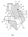
- the cutting tool (1) in Fig. 1 consists of a base part (20) in which a replaceable bit holder (10) can be used. Furthermore, the cutting tool (1) has a sealing element (30) and a pressure screw (40), which serves for fixing the bit holder (10) in the base part (20).
- the bit holder (10) consists of a base body (17) and has at its lower end an insertion projection (15) which in a corresponding thereto plug-in receptacle (22) on the base part. (20) can be used.
- the insertion movement of the chisel holder (10) in the base part (20) is limited in its rear region by a stop (11) on the bit holder (10) and by a, this opposite stop (24) on the base part (20).
- the insertion projection (15) has at its front edge at least one guide surface (15.1) which is guided by a corresponding prism guide (22.1) in the plug-in receptacle (22) during insertion of the bit holder (10).
- the bit holder (10) further has a chisel holder (12) into which a likewise easily replaceable turning tool can be inserted.
- the chisel holder (12) forms with its longitudinal axis at an acute angle to the axis of the plug-in extension (15).
- a sealing element (30) is mounted, which is adapted in its contour to the prism-shaped cross-section of the plug-in receptacle (15) with its guide surfaces (15.1).
- the sealing element (30) can be made angled according to the angle between the shoulder (21) and the stop (24) of the base part (20).
- the sealing element (30) in this case has an O-shaped cross section (31) in the region of the stop (24) and a cross-section thickened in the opposite direction in the region of the shoulder (21). In this case, this area is preferably designed as a wedge-shaped sealing lip (34).
- the base part In the area around the plug-in receptacle (22), the base part is provided with a bevel (23) encircling the plug-in receptacle (22), which serves as a seat for the sealing element (30).
- Fig. 2 shows the same cutting tool of Fig. 1 in section, after the bit holder (10) in the base part (20) is fully inserted.
- the pressure screw (40) which is preferably designed as a grub screw and has a thread (41) and a flattened pin (42), acts with its pin (42) a pressure surface (14) which is formed by a V-shaped recess (13) on the, the guide surface (15.1) opposite side of the plug-in projection (15).
- Fig. 3a and 3b show an embodiment of the sealing element (30) in plan view and in side view.
- the sealing element (30) is designed as a molded part, which has the contour of the circumference of the plug-in projection (15) of the bit holder (10). Corresponding to the angle between the shoulder (21) and the abutment (24) of the base part (20), the sealing element (30) is angled, wherein the sealing element (30) has at least one section with O-shaped cross-section (31), which on the Stop (24) of the base part (20) is applied.
- the angled portion (32) which bears against the shoulder (21) of the base part (20) has a cross section which is thickened in accordance with the distance (16).
- a wedge-shaped sealing lip (34) executed angled portion (32) increases the sealing effect.
- the sealing element (30) is formed from permanently elastic material and preferably designed as an injection molded part.
- the materials used are silicones. Examples are so-called liquid silicone rubber (LSR), z. B. SILOPREN® from GE BAYER Silicones, which can be produced by means of the so-called Liquid Injection Molding (LIM).
- suitable thermoplastic elastomers for. B. SANTOPRENE® from ADVANCED ELASTOMER SYSTEMS, which can be processed in the normal injection molding process. The usual during injection molding sprue is laid in the thickened region of the distance (16), so that the sprue nose (33) does not affect the sealing effect of the sealing element (30).
- sealing element (30) may be formed directly on the integrally formed plug projection (15) of the chisel holder (10), thereby surrounding the plug projection (15) at least in regions on its outer circumference.
- sealing element (30) on the base part (20) in the region around the plug receptacle (22) is formed directly and surrounds the plug receptacle (22) at least partially on its outer periphery.
- the invention is not limited to the cross-sectional shape of a plug-in extension (15) shown here. Rather, any other cross-sectional variants are conceivable, such as round cross-sections or plug-in lugs with a conical shape.
- the plug-in receptacle (22) in the base part (20) facing away from the bit holder (10) is open. This opening is in communication closed with the connected, not shown in the drawing Fräswalzenrohr by means of a weld joint.
Landscapes
- Engineering & Computer Science (AREA)
- Mining & Mineral Resources (AREA)
- Mechanical Engineering (AREA)
- Life Sciences & Earth Sciences (AREA)
- General Life Sciences & Earth Sciences (AREA)
- Geochemistry & Mineralogy (AREA)
- Geology (AREA)
- General Health & Medical Sciences (AREA)
- Nursing (AREA)
- Health & Medical Sciences (AREA)
- Percussive Tools And Related Accessories (AREA)
- Auxiliary Devices For Machine Tools (AREA)
- Processing Of Stones Or Stones Resemblance Materials (AREA)
- Gasket Seals (AREA)
- Cutting Tools, Boring Holders, And Turrets (AREA)
- Milling Processes (AREA)
- Pit Excavations, Shoring, Fill Or Stabilisation Of Slopes (AREA)
- Food-Manufacturing Devices (AREA)
- Component Parts Of Construction Machinery (AREA)
- Lubricants (AREA)
- Pharmaceuticals Containing Other Organic And Inorganic Compounds (AREA)
Abstract
Description
Die Erfindung betrifft ein Schrämwerkzeug einer Schrämmaschine, das ein Basisteil und einen Meißelhalter aufweist, wobei der Meißelhalter mit einem Steckansatz versehen ist, der in einer Steckaufnahme des Basisteils gehalten ist, und wobei die Steckaufnahme mit der Umgebung über eine oder mehrere Öffnungen in räumlicher Verbindung steht.The invention relates to a cutting tool of a cutting machine having a base part and a bit holder, wherein the bit holder is provided with a plug-in projection which is held in a socket of the base part, and wherein the plug-in receptacle is in spatial communication with the environment via one or more openings ,
Ein solches Schrämwerkzeug ist aus der
Zur Aufnahme der im Betrieb auftretenden Kräfte weist das Basisteil einen Anschlag auf, an dem sich der Meißelhalter abstützt. Damit die Wirkung des Anschlags erhalten bleibt und eine Belastung des Steckansatzes und der Steckaufnahme weitestgehend vermieden wird, ist der Meißelhalter im Bereich um die Steckaufnahme um einen Nachsetzraum beabstandet angeordnet.To accommodate the forces occurring during operation, the base part has a stop on which the bit holder is supported. So that the effect of the stop is maintained and a load on the plug-in extension and the plug-in receptacle is largely avoided, the bit holder is arranged in the region around the plug-in receptacle spaced around a Nachsetzraum.
Bei solchen Schrämwerkzeugen, wie sie beispielsweise im Straßenbau eingesetzt werden, hat es sich als nachteilig erwiesen, dass Gesteinspulver und Wasser in den Bereich des Steckansatzes und der Steckaufnahme eindringen. Gesteinspulver und Feuchtigkeit können dazu führen, dass sich der Steckansatz in der Steckaufnahme sowie die Druckschraube festsetzen. Dadurch kann der Meißelhalter nur mit erhöhtem Aufwand vom Basisteil gelöst werden. Häufig werden die Teile beim gewaltsamen Trennen beschädigt, was zu einem kostenintensiven Ersatz führt. Weiterhin führt das Gesteinspulver in diesem Bereich zu einem erhöhten Verschleiß, was zu kürzeren Standzeiten des Werkzeugs und somit zu höheren Betriebskosten führt. Verschmutzungen, die sich in der Steckaufnahme von der Innenseite an der Druckschraube festsetzen werden beim Lösen der Druckschraube zum Werkzeugwechsel in die Gewindeaufnahme des Basisteils hineingearbeitet und beschädigen dieses. Eine dann erforderliche Reparatur oder ein Tausch des Basisteils ist nur aufwendig durchführbar, weil das Basisteil üblicherweise mit dem Fräswalzenrohr und den benachbarten Basisteilen verschweißt ist.In such Schrämwerkzeugen as they are used for example in road construction, it has proved to be disadvantageous that rock powder and water penetrate into the region of the plug-in approach and the plug-in receptacle. Rock powder and moisture can cause the plug in the socket and the pressure screw to settle. As a result, the bit holder can be solved only with increased effort from the base. Often the parts are damaged in violent separation, resulting in a costly replacement. Furthermore, the rock powder in this area leads to increased wear, resulting in shorter tool life and thus higher operating costs. Dirt that settle in the socket from the inside of the pressure screw are working when loosening the pressure screw for tool change in the threaded receptacle of the base and damage it. A then required repair or replacement of the base part is expensive to carry out only because the base part is usually welded to the Fräswalzenrohr and the adjacent base parts.
Besonders nachteilig wirken sich Verunreinigungen am Steckansatz des Meißelhalters und im Bereich der Steckaufnahme des Basisteils aus. Die hier angesetzten Partikel werden beim späteren Maschinenbetrieb zertrümmert. Dabei entsteht dann ein Spiel zwischen dem Steckansatz und der Stechaufnahme. Die paßgenaue Positionierung des Meißelhalters ist dann nicht mehr sichergestellt. Dies wirkt sich vor allem beim sogenannten Feinfräsen negativ aus. Dieses, in der Praxis an Bedeutung gewinnende Verfahren dient dazu Fahrbahnoberflächen in einem Bearbeitungsschritt in endgültiger Qualität zu fräsen. Voraussetzung hierfür ist, daß die Meißelhalter exakt positioniert sind. Wenn ein Meißelhalter dieses Kriterium nicht erfüllt, dann erzeugt er eine Fehlstelle im Fräsbild, die das Gesamt- Ergebnis beeinflußt. Ein - gelockert im Basisteil sitzender Meißelhalter kann somit die Fräsqualität entscheidend verschlechtern. Weiterhin kann es vorkommen, daß sich der gelockerte Meißel vollständig vom Basisteil löst und dann gravierende Werkzeugschäden verursacht.Impurities are particularly disadvantageous on the insertion projection of the chisel holder and in the region of the plug-in receptacle of the base part. The particles used here are smashed during later machine operation. This creates a game between the plug-in approach and the pricking. The Precision positioning of the chisel holder is then no longer ensured. This has a negative effect especially in so-called fine milling. This method, which is gaining in importance in practice, is used to mill road surfaces to final quality in one processing step. The prerequisite for this is that the bit holders are exactly positioned. If a chisel holder does not meet this criterion, then it creates a defect in the milling pattern that affects the overall result. A chisel holder sitting loosely in the base part can thus decisively worsen the milling quality. Furthermore, it may happen that the loosened chisel completely detached from the base part and then causes serious damage to the tool.
Es ist Aufgabe der Erfindung, ein Schrämwerkzeug der eingangs erwähnten Art zu schaffen, bei dem die Werkzeug- Standzeit, insbesondere des Basisteils verbessert ist.It is an object of the invention to provide a cutting tool of the type mentioned, in which the tool life, in particular of the base part is improved.
Diese Aufgabe wird dadurch gelöst, daß zumindest eine der Öffnungen wenigstens bereichsweise mit einem Dichtungselement verschlossen ist.This object is achieved in that at least one of the openings is closed at least partially with a sealing element.
Das Dichtungselement schützt den zwischen dem Steckansatz und dem Basisteil gebildeten Übergangsbereich der Steckaufnahme. Es verhindert auf einfache und wirkungsvolle Weise das Eindringen von Abraummaterial und Wasser in die Steckaufnahme. Wenn der Meißelhalter seinen Verschleißzustand erreicht hat, kann er aus der Steckaufnahme herausgezogen werden. Der von der Steckaufnahme gebildete Aufnahmeraum bleibt unverschmutzt oder im wesentlichen verschmutzungsfrei. Ein neuer Meißelhalter kann dann mit geringem Zeitaufwand exakt positioniert und befestigt werden. Das Dichtungselement bildet somit ein einfaches Bauteil, das einen effektiven Werkzeugwechsel gestattet und gleichzeitig die Lebensdauer des Basisteils wesentlich erhöht. Das Dichtungselement kann auch von einer Fettschicht gebildet sein.The sealing element protects the transition region of the plug-in receptacle formed between the plug-in projection and the base part. It prevents in a simple and effective way the penetration of space material and water into the socket. When the bit holder has reached its wear state, it can be pulled out of the socket. The receiving space formed by the plug-in receptacle remains unpolluted or substantially free of contamination. A new bit holder can then be accurately positioned and fixed with little time. The sealing element thus forms a simple component which allows an effective tool change and at the same time substantially increases the service life of the base part. The sealing element may also be formed by a layer of grease.
Abhängig von der Gestalt und Anordnung des Dichtelementes wird ein reproduzierbare und paßgenaue Positionierung des Meißelhalters möglich.Depending on the shape and arrangement of the sealing element, a reproducible and precise positioning of the chisel holder becomes possible.
Gemäß einer bevorzugten Ausgestaltungsvariante der Erfindung kann es vorgesehen sein, daß das Dichtungselement zwischen dem Meißelhalter und dem Basisteil zumindest bereichsweise um die Steckaufnahme angeordnet ist. Damit wird ein Bereich geschützt, über den häufig massiv Verunreinigungen eindringen können.According to a preferred embodiment variant of the invention, it may be provided that the sealing element between the bit holder and the base part is arranged at least partially around the plug receptacle. This protects an area that can often penetrate massive contaminants.
Eine besonders gute Abdichtung wird dadurch erreicht, dass das Dichtungselement als Formteil ausgeführt ist, welches die Kontur des Umfanges des Steckansatzes des Meißelhalters aufweist. Weiterhin ist die Ausgestaltung besonders montagefreundlich, da das Dichtungselement zur Montage auf den Steckansatz des Meißelhalters aufgesetzt und dann gemeinsam mit dem Meißelhalter in das Basisteil eingesetzt werden kann.A particularly good seal is achieved in that the sealing element is designed as a molded part, which has the contour of the circumference of the plug-neck of the bit holder. Furthermore, the design is particularly easy to install, since the sealing element can be placed for mounting on the plug neck of the bit holder and then used together with the bit holder in the base part.
Dadurch, dass das Basisteil um die Steckaufnahme eine umlaufende Fase aufweist, welche als Sitz für das Dichtungselement dient, wird erreicht, dass das Dichtungselement während des Betriebes unverrückbar sitzt. Weiterhin bietet die Fase den Raum, in den das Dichtungselement bei der Montage definiert eingepresst wird, ohne dass es dabei zerstört werden kann. Hierdurch wird eine optimale Dichtwirkung erzielt.The fact that the base part has a circumferential chamfer around the plug-in receptacle, which serves as a seat for the sealing element, ensures that the sealing element sits immovably during operation. Furthermore, the chamfer provides the space in which the sealing element is pressed defined during assembly, without it can be destroyed. As a result, an optimum sealing effect is achieved.
Eine dauerhafte Abdichtung des zu schützenden Bereiches wird dadurch erreicht, dass das Dichtungselement aus einem dauerelastischen Material, vorzugsweise aus Silikon oder aus einem thermoplastischen Elastomer besteht.A permanent sealing of the area to be protected is achieved in that the sealing element consists of a permanently elastic material, preferably of silicone or of a thermoplastic elastomer.
Eine bevorzugte Ausgestaltung sieht vor, dass der Meißelhalter mit seinem Anschlag an dem Anschlag des Basisteils anliegt, dass das Basisteil einen Absatz aufweist, der im Winkel zu dem Anschlag steht, dass zwischen dem Absatz des Basisteils und der dem Absatz zugekehrten Seite des Meißelhalters ein als Nachsetzraum wirkender Abstand ausgebildet ist, wobei das Dichtungselement derart ausgeformt ist, dass es diesen Abstand überbrückt. Hiermit wird erreicht, dass kein Gesteinspulver und Wasser über den Nachsetzraum in die Steckaufnahme eindringen kann.A preferred embodiment provides that the bit holder rests with its stop on the stop of the base part, that the base part has a shoulder which is at an angle to the stop, that between the shoulder of the base part and the paragraph facing side of the bit holder as Nachsetzraum acting distance is formed, wherein the sealing element is formed in such a way is that it bridges this gap. This ensures that no rock powder and water can penetrate through the Nachsetzraum in the socket.
Eine besonders leichte Montage und sichere Dichtwirkung wird dadurch erreicht, dass das Dichtungselement entsprechend dem Winkel zwischen dem Absatz und dem Anschlag des Basisteils abgewinkelt ist.A particularly easy assembly and secure sealing effect is achieved in that the sealing element is angled in accordance with the angle between the shoulder and the stop of the base part.
Eine gute Abdichtung der unterschiedlichen Spaltbreiten im Bereich des Anschlags und des Nachsetzraums kann dadurch erreicht werden, dass das Dichtungselement einen Abschnitt mit O-förmigen Querschnitt aufweist, der zumindest bereichsweise an dem Anschlag des Basisteils anliegt und einen gegen diesen abgewinkelten Abschnitt aufweist, der an dem Absatz des Basisteils anliegt und einen, den Abstand zumindest bereichsweise überbrückenden verdickten Querschnitt aufweist.A good sealing of the different gap widths in the region of the abutment and the Nachsetzraums can be achieved, that the sealing element has a portion of O-shaped cross-section which rests at least partially against the stop of the base member and has an angled against this portion which on the Has paragraph of the base part and a, the distance at least partially bridging thickened cross-section.
Eine vorteilhafte Ausgestaltung der Erfindung sieht vor, dass der abgewinkelte Abschnitt eine keilförmige Dichtlippe aufweist, welche an die Form des Nachsetzraumes angepasst ist. Hierdurch werden Unebenheiten und Fertigungstoteranzen am Meißelhalter und Basisteil ausgeglichen.An advantageous embodiment of the invention provides that the angled section has a wedge-shaped sealing lip, which is adapted to the shape of the Nachsetzraumes. As a result, unevenness and manufacturing robotics on chisel holder and base are compensated.
Eine kostengünstige Herstellung, auch in großen Stückzahlen, sowie enge Toleranzen und ein an das Herstellverfahren angepasstes Design wird dadurch ermöglicht, dass das Dichtungselement als Spritzgussteil ausgeführt ist und die Angußnase im Bereich des entsprechend des Abstands verdickten Querschnitts angeordnet ist. Hierdurch wird erreicht, dass die Angussnase die Dichtwirkung des Dichtungselementes nicht beeinträchtigt.A cost-effective production, even in large quantities, as well as tight tolerances and adapted to the manufacturing process design is made possible by the fact that the sealing element is designed as an injection molded part and the sprue is arranged in the region of the corresponding thickened cross-section cross section. This ensures that the sprue nose does not affect the sealing effect of the sealing element.
Eine leichte und passgenaue Montage des Meißelhalters in das Basisteil wird erreicht, indem das Dichtungselement als separates Kunststoff - Bauteil auf den Steckansatz aufgezogen ist oder das Dichtungselement an den Steckansatz als Kunststoff - Bauteil angespritzt ist.A simple and precise fitting of the chisel holder in the base part is achieved by the sealing element is mounted as a separate plastic component on the plug-in approach or the sealing element is molded onto the plug-in approach as a plastic component.
Eine bevorzugte Ausgestaltung der Erfindung sieht vor, dass der Meißelhalter für das Schrämwerkzeug mit einem an einen Grundkörper angeformten Steckansatz versehen ist, und der Steckansatz ein Dichtungselement aufweist, das den Steckansatz zumindest bereichsweise an seinem Außenumfang umgibt. Hierdurch wird erreicht, dass der Meißelhalter mit dem Steckansatz und dem Dichtungselement als Baueinheit vorgeformt werden, als Einheit bevorratet und als Ersatzteil schnell und kostengünstig montiert werden kann.A preferred embodiment of the invention provides that the bit holder for the cutting tool is provided with an integrally formed on a base plug-in, and the plug-in approach has a sealing element surrounding the plug-in approach at least partially on its outer periphery. This ensures that the bit holder can be preformed with the plug-in approach and the sealing element as a unit, stored as a unit and can be mounted as a spare quickly and inexpensively.
Die Erfindung wird im folgenden anhand eines in den Figuren dargestellten Ausführungsbeispiels näher erläutert. Es zeigen:
- Fig. 1
- im teilmontierten Zustand ein Schrämwerkzeug mit einem auswechselbaren Meißelhalter in Seitenansicht und im Schnitt
- Fig. 2
- das Schrämwerkzeug gemäß Fig. 1 mit eingesetztem Meißelhalter in Seitenansicht und im Schnitt
- Fig. 3a
- ein Dichtungselement in der Draufsicht
- Fig. 3b
- das Dichtungselement gemäß Fig. 3a in der Seitenansicht
- Fig. 1
- in partially assembled state a cutting tool with a replaceable bit holder in side view and in section
- Fig. 2
- the cutting tool of FIG. 1 with inserted bit holder in side view and in section
- Fig. 3a
- a sealing element in plan view
- Fig. 3b
- the sealing element of FIG. 3a in side view
Das Schrämwerkzeug (1) in Fig. 1 besteht aus einem Basisteil (20), in dem ein auswechselbarer-Meißelhalter (10) eingesetzt werden kann. Weiterhin weist das Schrämwerkzeug (1) ein Dichtungselement (30) und eine Druckschraube (40) auf, die zur Fixierung des Meißelhalters (10) in dem Basisteil (20) dient.The cutting tool (1) in Fig. 1 consists of a base part (20) in which a replaceable bit holder (10) can be used. Furthermore, the cutting tool (1) has a sealing element (30) and a pressure screw (40), which serves for fixing the bit holder (10) in the base part (20).
Der Meißelhalter (10) besteht aus einem Grundkörper (17) und besitzt an seinem unteren Ende einen Steckansatz (15), der in eine dazu korrespondierende Steckaufnahme (22) am Basisteil. (20) eingesetzt werden kann. Die Einschubbewegung des Meißelhalters (10) in das Basisteil (20) wird in seinem rückwärtigen Bereich durch einen Anschlag (11) am Meißelhalter (10) und durch einen, diesem gegenüberliegenden Anschlag (24) am Basisteil (20) begrenzt. Der Steckansatz (15) weist an seiner Vorderkante mindestens eine Führungsfläche (15.1) auf, die von einer entsprechenden Prismenführung (22.1) in der Steckaufnahme (22) beim Einschieben des Meißelhalters (10) geführt wird.The bit holder (10) consists of a base body (17) and has at its lower end an insertion projection (15) which in a corresponding thereto plug-in receptacle (22) on the base part. (20) can be used. The insertion movement of the chisel holder (10) in the base part (20) is limited in its rear region by a stop (11) on the bit holder (10) and by a, this opposite stop (24) on the base part (20). The insertion projection (15) has at its front edge at least one guide surface (15.1) which is guided by a corresponding prism guide (22.1) in the plug-in receptacle (22) during insertion of the bit holder (10).
Der Meißelhalter (10) besitzt weiterhin eine Meißelaufnahme (12), in die ein ebenfalls leicht austauschbarer Drehmeißel eingesetzt werden kann. Die Meißelaufnahme (12) bildet mit ihrer Längsachse einen spitzen Winkel zur Achse des Steckansatzes (15).The bit holder (10) further has a chisel holder (12) into which a likewise easily replaceable turning tool can be inserted. The chisel holder (12) forms with its longitudinal axis at an acute angle to the axis of the plug-in extension (15).
Auf den Steckansatz (15) ist ein Dichtungselement (30) aufgezogen, welches in seiner Kontur an den prismenförmigen Querschnitt der Steckaufnahme (15) mit seinen Führungsflächen (15.1) angepasst ist. Das Dichtungselement (30) kann entsprechend dem Winkel zwischen dem Absatz (21) und dem Anschlag (24) des Basisteils (20) abgewinkelt ausgeführt sein. Das Dichtungselement (30) besitzt dabei einen O-förmigen Querschnitt (31) im Bereich des Anschlags (24) und einen dem gegenüber verdickten Querschnitt im Bereich des Absatzes (21). Dabei ist dieser Bereich vorzugsweise als eine keilförmige Dichtlippe (34) ausgeführt.On the plug-in projection (15) a sealing element (30) is mounted, which is adapted in its contour to the prism-shaped cross-section of the plug-in receptacle (15) with its guide surfaces (15.1). The sealing element (30) can be made angled according to the angle between the shoulder (21) and the stop (24) of the base part (20). The sealing element (30) in this case has an O-shaped cross section (31) in the region of the stop (24) and a cross-section thickened in the opposite direction in the region of the shoulder (21). In this case, this area is preferably designed as a wedge-shaped sealing lip (34).
Im Bereich um die Steckaufnahme (22) ist das Basisteil mit einer um die Steckaufnahme (22) umlaufende Fase (23) versehen, welche als Sitz für das Dichtungselement (30) dient.In the area around the plug-in receptacle (22), the base part is provided with a bevel (23) encircling the plug-in receptacle (22), which serves as a seat for the sealing element (30).
Fig. 2 zeigt das gleiche Schrämwerkzeug aus Fig. 1 im Schnitt, nachdem der Meißelhalter (10) in das Basisteil (20) vollständig eingesetzt ist. Dabei wirkt die Druckschraube (40), die vorzugsweise als Madenschraube ausgeführt ist und ein Gewinde (41) und einen abgeflachten Zapfen (42) besitzt, mit ihrem Zapfen (42) auf eine Druckfläche (14), die durch eine V-förmige Aussparung (13) an der, der Führungsfläche (15.1) gegenüberliegenden Seite des Steckansatzes (15) gebildet wird.Fig. 2 shows the same cutting tool of Fig. 1 in section, after the bit holder (10) in the base part (20) is fully inserted. In this case, the pressure screw (40), which is preferably designed as a grub screw and has a thread (41) and a flattened pin (42), acts with its pin (42) a pressure surface (14) which is formed by a V-shaped recess (13) on the, the guide surface (15.1) opposite side of the plug-in projection (15).
Beim Anziehen der Druckschraube (40) ergeben sich resultierende Kräfte, die den Meißelhalter (10) in das Basisteil (20) drücken. Dabei stützt sich der Anschlag (11) des Meißelhalters (10) an dem Anschlag (24) des Basisteils ab. Das Dichtungselement (30) setzt sich dabei mit seinem Abschnitt mit O-förmigen Querschnitt (31) in die als Dichtungssitz ausgebildete Fase (23) des Basisteils (20). Dabei wird der ursprüngliche 0-förmige Querschnitt derart gepresst, dass eine optimale Dichtwirkung erzielt wird.When tightening the pressure screw (40) results in resulting forces that press the bit holder (10) in the base part (20). In this case, the stop (11) of the chisel holder (10) is supported on the stop (24) of the base part. The sealing element (30) sits down with its section with an O-shaped cross section (31) in the formed as a seal seat chamfer (23) of the base part (20). In this case, the original 0-shaped cross-section is pressed so that an optimum sealing effect is achieved.
Zwischen dem Absatz (21) im vorderen Teil des Basisteils (20) und der dem Absatz (21) gegenüberliegenden Fläche des Meißelhalters (10) ist ein als Nachsetzraum wirkender Abstand (16) ausgebildet. Das Dichtungselement (30) überbrückt aufgrund seines in diesem Bereich verdickten Querschnitts und der gleichzeitigen Ausbildung als keilförmige Dichtlippe (34) den Abstand (16) wodurch ebenfalls eine optimale Dichtwirkung erzielt wird. Damit wird erreicht, dass keine Abraumpartikel in den Bereich der Steckaufnahme eindringen können. Dies erleichtert den Austausch der Meißelhalter (10). Gleichzeitig wird durch diese Anordnung erreicht, dass kein Wasser mit Abraumpartikeln in den Bereich des Zapfens (42) und der Druckfläche (14) des Steckansatzes (15) eindringen kann.Between the shoulder (21) in the front part of the base part (20) and the opposite surface of the chisel holder (10) (21) acting as Nachsetzraum distance (16) is formed. The sealing element (30) due to its thickened in this area cross section and the simultaneous training as a wedge-shaped sealing lip (34) bridges the distance (16) whereby also an optimal sealing effect is achieved. This ensures that no Abraumpartikel can penetrate into the area of the plug-in receptacle. This facilitates the replacement of the bit holder (10). At the same time is achieved by this arrangement that no water with Abraumpartikeln in the region of the pin (42) and the pressure surface (14) of the plug-in projection (15) can penetrate.
Fig. 3a und 3b zeigen eine Ausführungsform des Dichtungselementes (30) in Draufsicht und in der Seitenansicht.Fig. 3a and 3b show an embodiment of the sealing element (30) in plan view and in side view.
Das Dichtungselement (30) ist als Formteil ausgeführt, welches die Kontur des Umfanges des Steckansatzes (15) des Meißelhalters (10) aufweist. Entsprechend dem Winkel zwischen dem Absatz (21) und dem Anschlag (24) des Basisteils (20) ist das Dichtungselement (30) abgewinkelt, wobei das Dichtungselement (30) mindestens einen Abschnitt mit O-förmigen Querschnitt (31) aufweist, der an dem Anschlag (24) des Basisteils (20) anliegt. Der abgewinkelte Abschnitt (32), der an dem Absatz (21) des Basisteils (20) anliegt, weist einen entsprechend dem Abstand (16) verdickten Querschnitt auf. Ein als keilförmige Dichtlippe (34) ausgeführter abgewinkelter Abschnitt (32) erhöht dabei die Dichtwirkung.The sealing element (30) is designed as a molded part, which has the contour of the circumference of the plug-in projection (15) of the bit holder (10). Corresponding to the angle between the shoulder (21) and the abutment (24) of the base part (20), the sealing element (30) is angled, wherein the sealing element (30) has at least one section with O-shaped cross-section (31), which on the Stop (24) of the base part (20) is applied. The angled portion (32) which bears against the shoulder (21) of the base part (20) has a cross section which is thickened in accordance with the distance (16). A wedge-shaped sealing lip (34) executed angled portion (32) increases the sealing effect.
Das Dichtungselement (30) ist dabei aus dauerelastischem Material gebildet und vorzugsweise als Spritzgussteil ausgeführt. Als Materialien kommen Silikone zum Einsatz. Beispiele dafür sind sogenannte Liquid-Silicone-Rubber (LSR), z. B. SILOPREN® von GE BAYER Silicones, die mittels dem sogenannten Liquid-Injection-Molding (LIM) hergestellt werden können. Weiterhin geeignet sich thermoplastische Elastomere, z. B. SANTOPRENE® von ADVANCED ELASTOMER SYSTEMS, die im normalen Spritzgussprozess verarbeitet werden können. Der beim Spritzgussprozess übliche Anguss ist dabei in den verdickten Bereich des Abstands (16) verlegt, so dass die Angussnase (33) die Dichtwirkung des Dichtungselementes (30) nicht beeinträchtigt.The sealing element (30) is formed from permanently elastic material and preferably designed as an injection molded part. The materials used are silicones. Examples are so-called liquid silicone rubber (LSR), z. B. SILOPREN® from GE BAYER Silicones, which can be produced by means of the so-called Liquid Injection Molding (LIM). Furthermore, suitable thermoplastic elastomers, for. B. SANTOPRENE® from ADVANCED ELASTOMER SYSTEMS, which can be processed in the normal injection molding process. The usual during injection molding sprue is laid in the thickened region of the distance (16), so that the sprue nose (33) does not affect the sealing effect of the sealing element (30).
Weiterhin kann es vorgesehen sein, dass das Dichtungselement (30) an den angeformten Steckansatz (15) des Meißelhalters (10) direkt angeformt ist und dabei den Steckansatz (15) zumindest bereichsweise an seinem Außenumfang umgibt. Ebenso kann es vorgesehen sein, dass das Dichtungselement (30) an das Basisteil (20) im Bereich um die Steckaufnahme (22) direkt angeformt ist und die Steckaufnahme (22) zumindest bereichsweise an ihrem Außenumfang umgibt.Furthermore, provision may be made for the sealing element (30) to be formed directly on the integrally formed plug projection (15) of the chisel holder (10), thereby surrounding the plug projection (15) at least in regions on its outer circumference. Likewise, it may be provided that the sealing element (30) on the base part (20) in the region around the plug receptacle (22) is formed directly and surrounds the plug receptacle (22) at least partially on its outer periphery.
An dieser Stelle sei noch erwähnt daß die Erfindung nicht auf die vorliegend gezeigte Querschnittsform eines Steckansatzes (15) beschränkt ist. Vielmehr sind auch beliebige andere Querschnittsvarianten denkbar, wie zum Beispiel runde Querschnitte oder Steckansätze mit einem konischen Verlauf.At this point it should be mentioned that the invention is not limited to the cross-sectional shape of a plug-in extension (15) shown here. Rather, any other cross-sectional variants are conceivable, such as round cross-sections or plug-in lugs with a conical shape.
Wie aus den Zeichnungen ersichtlich ist, ist die Steckaufnahme (22) im Basisteil (20) dem Meißelhalter (10) abgekehrt offen ausgeführt. Diese Öffnung ist in Verbindung mit dem angeschlossenen, in der Zeichnung nicht dargestellten Fräswalzenrohr mittels einer Schweißnaht Verbindung geschlossen.As can be seen from the drawings, the plug-in receptacle (22) in the base part (20) facing away from the bit holder (10) is open. This opening is in communication closed with the connected, not shown in the drawing Fräswalzenrohr by means of a weld joint.
Claims (10)
- Cutting tool of a cutting machine, comprising a base part (20) and a bit holder (10), the bit holder being provided with a plug-in attachment (15) retained in a socket (22) of the base part, the socket being in a spatial connection with the surrounding environment via one or a plurality of openings, the bit holder (10) making contact with an abutment (11) on an abutment (24) of the base part (20), the base part (20) exhibiting a shoulder (21), which is set at an angle to the abutment (24), a distance (16) acting as an adjustment space being formed between the shoulder (21) of the base part (20) and the side of the bit holder (10) facing the shoulder (21), characterized in that at least the opening formed by the socket is closed in at least some areas by means of a sealing element and the sealing element (30) is executed in such a way that it bridges this distance (16).
- Cutting tool according to Claim 1, characterized in that the sealing element (30) is arranged between the bit holder (10) and the base part (20) around the socket (22) in at least some areas.
- Cutting tool according to Claim 1 or 2, characterized in that the sealing element (30) is configured as a preformed part, which exhibits the contour of the periphery of the plug-in attachment (15) of the bit holder (10).
- Cutting tool according to one of Claims 1 to 3, characterized in that the base part (20) exhibits an at least partially circumferential chamfer (23) around the sockets (22), which serves as a seat for the sealing element (30).
- Cutting tool according to one of Claims 1 to 4, characterized in that the sealing element (30) consists of a permanently elastic material, preferably silicone, or a thermoplastic elastomer.
- Cutting tool according to one of Claims 1 to 5, characterized in that the sealing element (30) is angled according to the angle between the shoulder (21) and the abutment (24) of the base part (20).
- Cutting tool according to one of Claims 1 to 6, characterized in that the sealing element (30) exhibits a section having an O-shaped cross section (31), which makes contact at least partially with an area of the base part (20) allocated to the abutment (24) and exhibits a section (32) angled thereto, which section makes contact with the shoulder (21) of the base part (20) and exhibits a thickened cross section bridging the distance (16) in at least some areas.
- Cutting tool according to Claim 7, characterized in that the angled section (32) exhibits a wedge-shaped sealing lip (34).
- Cutting tool according to one of Claims 7 or 8, characterized in that the sealing element (30) is executed as an injection moulded component part, and the sprue (33) is arranged in the area of the thickened cross section corresponding to the distance (16).
- Cutting tool according to one of Claims 1 to 9, characterized in that the sealing element (30) is attached to the plug-in attachment (15) as a separate plastic component part, or in that the sealing element (30) is injection-moulded on the plug-in attachment (15) as a plastic component part.
Applications Claiming Priority (3)
| Application Number | Priority Date | Filing Date | Title |
|---|---|---|---|
| DE10261646 | 2002-12-27 | ||
| DE10261646A DE10261646B4 (en) | 2002-12-27 | 2002-12-27 | Schrämwerkzeug |
| PCT/EP2003/011288 WO2004059128A1 (en) | 2002-12-27 | 2003-10-11 | Cutting tool |
Publications (2)
| Publication Number | Publication Date |
|---|---|
| EP1579105A1 EP1579105A1 (en) | 2005-09-28 |
| EP1579105B1 true EP1579105B1 (en) | 2007-08-22 |
Family
ID=32519501
Family Applications (1)
| Application Number | Title | Priority Date | Filing Date |
|---|---|---|---|
| EP03785617A Expired - Lifetime EP1579105B1 (en) | 2002-12-27 | 2003-10-11 | Cutting tool |
Country Status (12)
| Country | Link |
|---|---|
| US (1) | US7461903B2 (en) |
| EP (1) | EP1579105B1 (en) |
| KR (1) | KR100685320B1 (en) |
| CN (1) | CN100532785C (en) |
| AT (1) | ATE371095T1 (en) |
| AU (1) | AU2003294689A1 (en) |
| BR (1) | BR0317797B1 (en) |
| DE (3) | DE20221925U1 (en) |
| ES (1) | ES2290531T3 (en) |
| HK (1) | HK1076647A1 (en) |
| RU (1) | RU2304216C2 (en) |
| WO (1) | WO2004059128A1 (en) |
Families Citing this family (19)
| Publication number | Priority date | Publication date | Assignee | Title |
|---|---|---|---|---|
| DE10221764C1 (en) * | 2002-05-15 | 2003-11-27 | Wirtgen Gmbh | Holder for shaft chisel in milling machine has upper part with seating for shaft chisel secured to base part with clamp screw and clamp element for securing chisel shaft |
| DE102005003734B3 (en) * | 2005-01-26 | 2006-02-16 | Wirtgen Gmbh | Lathe tool holder socket is surrounded by a block that translates via a stress-relief groove to an angled side-extension |
| US9653601B2 (en) | 2005-07-11 | 2017-05-16 | Peregrine Semiconductor Corporation | Method and apparatus for use in improving linearity of MOSFETs using an accumulated charge sink-harmonic wrinkle reduction |
| DE102009059189A1 (en) * | 2009-12-17 | 2011-06-22 | Wirtgen GmbH, 53578 | Chisel holder and base part for holding a chisel holder |
| DE102009059188A1 (en) * | 2009-12-17 | 2011-06-22 | Wirtgen GmbH, 53578 | Chisel holder and base part |
| JP5822940B2 (en) | 2010-12-03 | 2015-11-25 | ヴィルトゲン ゲーエム ベーハーWirtgen Gesellschaft Mit Beschrankter Haftung | Chisel holder, and chisel holder system comprising the chisel holder and base portion |
| DE102010061019A1 (en) | 2010-12-03 | 2012-06-06 | Betek Gmbh & Co. Kg | Chisel holder and lower tool part for a chisel holder |
| TWI568919B (en) | 2010-12-03 | 2017-02-01 | Wirtgen Gmbh | Turret (a) |
| CN202705874U (en) | 2010-12-03 | 2013-01-30 | 维特根有限公司 | Knife holder |
| TWI483798B (en) | 2010-12-03 | 2015-05-11 | Wirtgen Gmbh | Chisel holder and chisel holder system with a chisel holder and a base |
| USD667854S1 (en) | 2011-04-11 | 2012-09-25 | Betek Gmbh & Co. Kg | Chisel holder |
| USD667855S1 (en) | 2011-04-11 | 2012-09-25 | Betek Gmbh & Co. Kg | Base for a chisel holder |
| USD666643S1 (en) | 2011-07-04 | 2012-09-04 | Wirtgen Gmbh | Chisel holder |
| DE102011051525A1 (en) | 2011-07-04 | 2013-01-10 | Wirtgen Gmbh | Chisel holder for a soil tillage machine |
| US9382795B2 (en) | 2012-12-12 | 2016-07-05 | Kennametal Inc. | Cutting tool mounting assembly |
| US8857917B2 (en) | 2012-12-12 | 2014-10-14 | Kennametal Inc. | Cutting tool mounting assembly |
| RU2666906C2 (en) | 2013-06-18 | 2018-09-13 | Эско Корпорейшн | Mineral winning pick, pick holder, and combination |
| CN106758694A (en) * | 2017-01-16 | 2017-05-31 | 徐工集团工程机械有限公司 | The tool apron device and cold regenerative machine of instrument are mixed in road surface cold renewal milling |
| TWI803397B (en) * | 2022-07-21 | 2023-05-21 | 施權航 | electric bed |
Family Cites Families (14)
| Publication number | Priority date | Publication date | Assignee | Title |
|---|---|---|---|---|
| FR2356831A1 (en) | 1976-06-29 | 1978-01-27 | Metafram | Drill bit for rock drill - is snapped into socket by radial deflection of garter spring in groove |
| DE2839292A1 (en) | 1978-09-09 | 1980-03-13 | Elfgen Apex | MILLING CHISEL FOR A MILLING DEVICE, IN PARTICULAR FOR MILLING OFF ROAD COVERINGS |
| GB2055434A (en) * | 1979-07-27 | 1981-03-04 | Hall & Pickles Ltd | A retention seal for mineral cutter picks and boxes |
| AT369859B (en) * | 1981-03-12 | 1983-02-10 | Voest Alpine Ag | DEVICE FOR COOLING THE CHISELS OF A BREWING MACHINE |
| AT375149B (en) * | 1982-07-06 | 1984-07-10 | Voest Alpine Ag | CHISEL HOLDER EQUIPPED WITH A SPRAYING DEVICE |
| DE3411602A1 (en) | 1982-11-13 | 1985-10-03 | Peters, Albert, 4000 Düsseldorf | Winning apparatus with rotary/tilting bit and sealed-off bit pocket |
| DE3300168A1 (en) | 1983-01-05 | 1984-07-05 | Elfgen-Apex GmbH, 5047 Wesseling | Cutting-pick holder for cutting machines and selective-cut heading machines |
| US4664450A (en) * | 1983-03-02 | 1987-05-12 | Padley & Venables Limited | Holder for a pick, and the combination of a pick and holder |
| DE9211739U1 (en) | 1992-09-01 | 1992-11-05 | Betek Bergbau- und Hartmetalltechnik Karl-Heinz Simon GmbH & Co KG, 7234 Aichhalden | Roller-shaped cutting body for a shearing machine |
| DE4322401C2 (en) * | 1993-07-06 | 1996-06-20 | Betek Bergbau & Hartmetall | Attachment of a cutting tool to a cutting body |
| US5725283A (en) * | 1996-04-16 | 1998-03-10 | Joy Mm Delaware, Inc. | Apparatus for holding a cutting bit |
| GB9704554D0 (en) | 1997-03-05 | 1997-04-23 | Bingham Engineering Ltd | Semi-locking pick box assembly |
| GB9804413D0 (en) * | 1998-03-03 | 1998-04-29 | Minnovation Ltd | Mineral cutting apparatus |
| US6113195A (en) * | 1998-10-08 | 2000-09-05 | Sandvik Ab | Rotatable cutting bit and bit washer therefor |
-
2002
- 2002-12-27 DE DE20221925U patent/DE20221925U1/en not_active Expired - Lifetime
- 2002-12-27 DE DE10261646A patent/DE10261646B4/en not_active Expired - Lifetime
-
2003
- 2003-10-11 KR KR1020057011967A patent/KR100685320B1/en active IP Right Grant
- 2003-10-11 WO PCT/EP2003/011288 patent/WO2004059128A1/en active IP Right Grant
- 2003-10-11 AT AT03785617T patent/ATE371095T1/en active
- 2003-10-11 US US10/540,805 patent/US7461903B2/en not_active Expired - Lifetime
- 2003-10-11 ES ES03785617T patent/ES2290531T3/en not_active Expired - Lifetime
- 2003-10-11 CN CNB2003801077814A patent/CN100532785C/en not_active Expired - Lifetime
- 2003-10-11 DE DE50308035T patent/DE50308035D1/en not_active Expired - Lifetime
- 2003-10-11 BR BRPI0317797-1A patent/BR0317797B1/en not_active IP Right Cessation
- 2003-10-11 EP EP03785617A patent/EP1579105B1/en not_active Expired - Lifetime
- 2003-10-11 RU RU2005123819/03A patent/RU2304216C2/en not_active IP Right Cessation
- 2003-10-11 AU AU2003294689A patent/AU2003294689A1/en not_active Abandoned
-
2005
- 2005-09-29 HK HK05108571A patent/HK1076647A1/en not_active IP Right Cessation
Also Published As
| Publication number | Publication date |
|---|---|
| HK1076647A1 (en) | 2006-01-20 |
| DE20221925U1 (en) | 2009-05-20 |
| CN100532785C (en) | 2009-08-26 |
| WO2004059128A1 (en) | 2004-07-15 |
| ES2290531T3 (en) | 2008-02-16 |
| EP1579105A1 (en) | 2005-09-28 |
| BR0317797B1 (en) | 2014-06-24 |
| RU2005123819A (en) | 2006-03-10 |
| DE10261646B4 (en) | 2010-02-25 |
| US7461903B2 (en) | 2008-12-09 |
| KR100685320B1 (en) | 2007-02-22 |
| KR20050091022A (en) | 2005-09-14 |
| US20060130342A1 (en) | 2006-06-22 |
| DE10261646A1 (en) | 2004-07-22 |
| CN1732327A (en) | 2006-02-08 |
| DE50308035D1 (en) | 2007-10-04 |
| BR0317797A (en) | 2005-11-22 |
| RU2304216C2 (en) | 2007-08-10 |
| ATE371095T1 (en) | 2007-09-15 |
| AU2003294689A1 (en) | 2004-07-22 |
Similar Documents
| Publication | Publication Date | Title |
|---|---|---|
| EP1579105B1 (en) | Cutting tool | |
| EP2646651B1 (en) | Chisel holder and lower tool part for a chisel holder | |
| DE19649621B4 (en) | Connection arrangement for melt channel sections in hot runners | |
| EP0816151A1 (en) | Fuel tank | |
| EP2215693A1 (en) | Arrangement for screw locking electric connecting terminals | |
| DE4440852C5 (en) | Closing device for liquid container, in particular battery plug and method for their preparation | |
| DE60206930T2 (en) | DEVICE WITH A SEAL BETWEEN TWO HOUSING TABLES | |
| DE4401622A1 (en) | Fastening device for a mounting link of a mother | |
| DE102021122574A1 (en) | Water tank with filter cartridge | |
| DE202011109172U1 (en) | Screw connection, glasses | |
| DE10306602B4 (en) | Sealing system for a shaft | |
| DE19601740C2 (en) | Sealed electrical connector | |
| DE202010013057U1 (en) | Chisel holder and lower tool part for a chisel holder | |
| DE69423136T2 (en) | Cast glazing and device for its production | |
| DE19541217C2 (en) | Sealing arrangement for a lamp | |
| DE102019206287B4 (en) | locking device | |
| DE8513179U1 (en) | Sealing arrangement | |
| EP1261074B1 (en) | Waterproof cable strain relief | |
| DE2121211A1 (en) | Elastomers under shear stress in power transmission systems | |
| DE102011119819A1 (en) | fastening device | |
| EP3850684B1 (en) | Seal arrangement for sealing a frame part | |
| DE9202872U1 (en) | Overflow pipe | |
| DE29619861U1 (en) | Plastic welding socket | |
| DE102011001237A1 (en) | Depth stopper for use in transferring arrangement of tool holder for transferring coolant or lubricant from tool holder to tool, has coolant channel and front surface that is provided for partial contact with front surface of tool | |
| DE29719333U1 (en) | Housing attachment for electrical connectors |
Legal Events
| Date | Code | Title | Description |
|---|---|---|---|
| PUAI | Public reference made under article 153(3) epc to a published international application that has entered the european phase |
Free format text: ORIGINAL CODE: 0009012 |
|
| 17P | Request for examination filed |
Effective date: 20050727 |
|
| AK | Designated contracting states |
Kind code of ref document: A1 Designated state(s): AT BE BG CH CY CZ DE DK EE ES FI FR GB GR HU IE IT LI LU MC NL PT RO SE SI SK TR |
|
| AX | Request for extension of the european patent |
Extension state: AL LT LV MK |
|
| REG | Reference to a national code |
Ref country code: HK Ref legal event code: DE Ref document number: 1076647 Country of ref document: HK |
|
| DAX | Request for extension of the european patent (deleted) | ||
| RIN1 | Information on inventor provided before grant (corrected) |
Inventor name: HOLL, BERND Inventor name: TEWES, GUENTER |
|
| GRAP | Despatch of communication of intention to grant a patent |
Free format text: ORIGINAL CODE: EPIDOSNIGR1 |
|
| GRAS | Grant fee paid |
Free format text: ORIGINAL CODE: EPIDOSNIGR3 |
|
| GRAA | (expected) grant |
Free format text: ORIGINAL CODE: 0009210 |
|
| AK | Designated contracting states |
Kind code of ref document: B1 Designated state(s): AT BE BG CH CY CZ DE DK EE ES FI FR GB GR HU IE IT LI LU MC NL PT RO SE SI SK TR |
|
| REG | Reference to a national code |
Ref country code: GB Ref legal event code: FG4D Free format text: NOT ENGLISH |
|
| REG | Reference to a national code |
Ref country code: CH Ref legal event code: EP |
|
| REG | Reference to a national code |
Ref country code: IE Ref legal event code: FG4D Free format text: LANGUAGE OF EP DOCUMENT: GERMAN |
|
| REF | Corresponds to: |
Ref document number: 50308035 Country of ref document: DE Date of ref document: 20071004 Kind code of ref document: P |
|
| REG | Reference to a national code |
Ref country code: SE Ref legal event code: TRGR |
|
| GBT | Gb: translation of ep patent filed (gb section 77(6)(a)/1977) |
Effective date: 20071029 |
|
| ET | Fr: translation filed | ||
| PG25 | Lapsed in a contracting state [announced via postgrant information from national office to epo] |
Ref country code: FI Free format text: LAPSE BECAUSE OF FAILURE TO SUBMIT A TRANSLATION OF THE DESCRIPTION OR TO PAY THE FEE WITHIN THE PRESCRIBED TIME-LIMIT Effective date: 20070822 Ref country code: BG Free format text: LAPSE BECAUSE OF FAILURE TO SUBMIT A TRANSLATION OF THE DESCRIPTION OR TO PAY THE FEE WITHIN THE PRESCRIBED TIME-LIMIT Effective date: 20071122 |
|
| REG | Reference to a national code |
Ref country code: ES Ref legal event code: FG2A Ref document number: 2290531 Country of ref document: ES Kind code of ref document: T3 |
|
| REG | Reference to a national code |
Ref country code: HK Ref legal event code: GR Ref document number: 1076647 Country of ref document: HK |
|
| REG | Reference to a national code |
Ref country code: IE Ref legal event code: FD4D |
|
| PG25 | Lapsed in a contracting state [announced via postgrant information from national office to epo] |
Ref country code: GR Free format text: LAPSE BECAUSE OF FAILURE TO SUBMIT A TRANSLATION OF THE DESCRIPTION OR TO PAY THE FEE WITHIN THE PRESCRIBED TIME-LIMIT Effective date: 20071123 Ref country code: DK Free format text: LAPSE BECAUSE OF FAILURE TO SUBMIT A TRANSLATION OF THE DESCRIPTION OR TO PAY THE FEE WITHIN THE PRESCRIBED TIME-LIMIT Effective date: 20070822 |
|
| PG25 | Lapsed in a contracting state [announced via postgrant information from national office to epo] |
Ref country code: SK Free format text: LAPSE BECAUSE OF FAILURE TO SUBMIT A TRANSLATION OF THE DESCRIPTION OR TO PAY THE FEE WITHIN THE PRESCRIBED TIME-LIMIT Effective date: 20070822 Ref country code: PT Free format text: LAPSE BECAUSE OF FAILURE TO SUBMIT A TRANSLATION OF THE DESCRIPTION OR TO PAY THE FEE WITHIN THE PRESCRIBED TIME-LIMIT Effective date: 20080122 Ref country code: MC Free format text: LAPSE BECAUSE OF NON-PAYMENT OF DUE FEES Effective date: 20071031 Ref country code: IE Free format text: LAPSE BECAUSE OF FAILURE TO SUBMIT A TRANSLATION OF THE DESCRIPTION OR TO PAY THE FEE WITHIN THE PRESCRIBED TIME-LIMIT Effective date: 20070822 |
|
| REG | Reference to a national code |
Ref country code: CH Ref legal event code: PL |
|
| PLBE | No opposition filed within time limit |
Free format text: ORIGINAL CODE: 0009261 |
|
| STAA | Information on the status of an ep patent application or granted ep patent |
Free format text: STATUS: NO OPPOSITION FILED WITHIN TIME LIMIT |
|
| PG25 | Lapsed in a contracting state [announced via postgrant information from national office to epo] |
Ref country code: RO Free format text: LAPSE BECAUSE OF FAILURE TO SUBMIT A TRANSLATION OF THE DESCRIPTION OR TO PAY THE FEE WITHIN THE PRESCRIBED TIME-LIMIT Effective date: 20070822 |
|
| 26N | No opposition filed |
Effective date: 20080526 |
|
| PG25 | Lapsed in a contracting state [announced via postgrant information from national office to epo] |
Ref country code: LI Free format text: LAPSE BECAUSE OF NON-PAYMENT OF DUE FEES Effective date: 20071031 Ref country code: CH Free format text: LAPSE BECAUSE OF NON-PAYMENT OF DUE FEES Effective date: 20071031 |
|
| PG25 | Lapsed in a contracting state [announced via postgrant information from national office to epo] |
Ref country code: EE Free format text: LAPSE BECAUSE OF FAILURE TO SUBMIT A TRANSLATION OF THE DESCRIPTION OR TO PAY THE FEE WITHIN THE PRESCRIBED TIME-LIMIT Effective date: 20070822 |
|
| PG25 | Lapsed in a contracting state [announced via postgrant information from national office to epo] |
Ref country code: SI Free format text: LAPSE BECAUSE OF FAILURE TO SUBMIT A TRANSLATION OF THE DESCRIPTION OR TO PAY THE FEE WITHIN THE PRESCRIBED TIME-LIMIT Effective date: 20070822 |
|
| PG25 | Lapsed in a contracting state [announced via postgrant information from national office to epo] |
Ref country code: CY Free format text: LAPSE BECAUSE OF FAILURE TO SUBMIT A TRANSLATION OF THE DESCRIPTION OR TO PAY THE FEE WITHIN THE PRESCRIBED TIME-LIMIT Effective date: 20070822 |
|
| PG25 | Lapsed in a contracting state [announced via postgrant information from national office to epo] |
Ref country code: LU Free format text: LAPSE BECAUSE OF NON-PAYMENT OF DUE FEES Effective date: 20071011 |
|
| PG25 | Lapsed in a contracting state [announced via postgrant information from national office to epo] |
Ref country code: HU Free format text: LAPSE BECAUSE OF FAILURE TO SUBMIT A TRANSLATION OF THE DESCRIPTION OR TO PAY THE FEE WITHIN THE PRESCRIBED TIME-LIMIT Effective date: 20080223 |
|
| REG | Reference to a national code |
Ref country code: FR Ref legal event code: PLFP Year of fee payment: 13 |
|
| REG | Reference to a national code |
Ref country code: DE Ref legal event code: R082 Ref document number: 50308035 Country of ref document: DE Representative=s name: HERRMANN, JOCHEN, DIPL.-ING., DE |
|
| REG | Reference to a national code |
Ref country code: FR Ref legal event code: PLFP Year of fee payment: 14 |
|
| REG | Reference to a national code |
Ref country code: FR Ref legal event code: PLFP Year of fee payment: 15 |
|
| REG | Reference to a national code |
Ref country code: FR Ref legal event code: PLFP Year of fee payment: 16 |
|
| PGFP | Annual fee paid to national office [announced via postgrant information from national office to epo] |
Ref country code: TR Payment date: 20190924 Year of fee payment: 17 Ref country code: CZ Payment date: 20190925 Year of fee payment: 17 |
|
| PGFP | Annual fee paid to national office [announced via postgrant information from national office to epo] |
Ref country code: NL Payment date: 20191021 Year of fee payment: 17 |
|
| PGFP | Annual fee paid to national office [announced via postgrant information from national office to epo] |
Ref country code: BE Payment date: 20191021 Year of fee payment: 17 Ref country code: ES Payment date: 20191122 Year of fee payment: 17 |
|
| PGFP | Annual fee paid to national office [announced via postgrant information from national office to epo] |
Ref country code: AT Payment date: 20191022 Year of fee payment: 17 |
|
| PG25 | Lapsed in a contracting state [announced via postgrant information from national office to epo] |
Ref country code: CZ Free format text: LAPSE BECAUSE OF NON-PAYMENT OF DUE FEES Effective date: 20201011 |
|
| REG | Reference to a national code |
Ref country code: NL Ref legal event code: MM Effective date: 20201101 |
|
| REG | Reference to a national code |
Ref country code: AT Ref legal event code: MM01 Ref document number: 371095 Country of ref document: AT Kind code of ref document: T Effective date: 20201011 |
|
| REG | Reference to a national code |
Ref country code: BE Ref legal event code: MM Effective date: 20201031 |
|
| PG25 | Lapsed in a contracting state [announced via postgrant information from national office to epo] |
Ref country code: NL Free format text: LAPSE BECAUSE OF NON-PAYMENT OF DUE FEES Effective date: 20201101 |
|
| PG25 | Lapsed in a contracting state [announced via postgrant information from national office to epo] |
Ref country code: BE Free format text: LAPSE BECAUSE OF NON-PAYMENT OF DUE FEES Effective date: 20201031 Ref country code: AT Free format text: LAPSE BECAUSE OF NON-PAYMENT OF DUE FEES Effective date: 20201011 |
|
| REG | Reference to a national code |
Ref country code: ES Ref legal event code: FD2A Effective date: 20220121 |
|
| PGFP | Annual fee paid to national office [announced via postgrant information from national office to epo] |
Ref country code: SE Payment date: 20211021 Year of fee payment: 19 Ref country code: DE Payment date: 20211020 Year of fee payment: 19 Ref country code: GB Payment date: 20211022 Year of fee payment: 19 |
|
| PGFP | Annual fee paid to national office [announced via postgrant information from national office to epo] |
Ref country code: IT Payment date: 20211029 Year of fee payment: 19 Ref country code: FR Payment date: 20211021 Year of fee payment: 19 |
|
| PG25 | Lapsed in a contracting state [announced via postgrant information from national office to epo] |
Ref country code: ES Free format text: LAPSE BECAUSE OF NON-PAYMENT OF DUE FEES Effective date: 20201012 |
|
| PG25 | Lapsed in a contracting state [announced via postgrant information from national office to epo] |
Ref country code: TR Free format text: LAPSE BECAUSE OF NON-PAYMENT OF DUE FEES Effective date: 20201011 |
|
| REG | Reference to a national code |
Ref country code: DE Ref legal event code: R119 Ref document number: 50308035 Country of ref document: DE |
|
| REG | Reference to a national code |
Ref country code: SE Ref legal event code: EUG |
|
| GBPC | Gb: european patent ceased through non-payment of renewal fee |
Effective date: 20221011 |
|
| PG25 | Lapsed in a contracting state [announced via postgrant information from national office to epo] |
Ref country code: FR Free format text: LAPSE BECAUSE OF NON-PAYMENT OF DUE FEES Effective date: 20221031 Ref country code: DE Free format text: LAPSE BECAUSE OF NON-PAYMENT OF DUE FEES Effective date: 20230503 |
|
| PG25 | Lapsed in a contracting state [announced via postgrant information from national office to epo] |
Ref country code: SE Free format text: LAPSE BECAUSE OF NON-PAYMENT OF DUE FEES Effective date: 20221012 |
|
| PG25 | Lapsed in a contracting state [announced via postgrant information from national office to epo] |
Ref country code: IT Free format text: LAPSE BECAUSE OF NON-PAYMENT OF DUE FEES Effective date: 20221011 Ref country code: GB Free format text: LAPSE BECAUSE OF NON-PAYMENT OF DUE FEES Effective date: 20221011 |