EP1579104B1 - Meisselanordnung für einen bohrhammer - Google Patents
Meisselanordnung für einen bohrhammer Download PDFInfo
- Publication number
- EP1579104B1 EP1579104B1 EP03773762A EP03773762A EP1579104B1 EP 1579104 B1 EP1579104 B1 EP 1579104B1 EP 03773762 A EP03773762 A EP 03773762A EP 03773762 A EP03773762 A EP 03773762A EP 1579104 B1 EP1579104 B1 EP 1579104B1
- Authority
- EP
- European Patent Office
- Prior art keywords
- bit
- drilling
- drill
- hole
- counter
- Prior art date
- Legal status (The legal status is an assumption and is not a legal conclusion. Google has not performed a legal analysis and makes no representation as to the accuracy of the status listed.)
- Expired - Lifetime
Links
Images

Classifications
-
- E—FIXED CONSTRUCTIONS
- E21—EARTH OR ROCK DRILLING; MINING
- E21B—EARTH OR ROCK DRILLING; OBTAINING OIL, GAS, WATER, SOLUBLE OR MELTABLE MATERIALS OR A SLURRY OF MINERALS FROM WELLS
- E21B10/00—Drill bits
- E21B10/26—Drill bits with leading portion, i.e. drill bits with a pilot cutter; Drill bits for enlarging the borehole, e.g. reamers
- E21B10/32—Drill bits with leading portion, i.e. drill bits with a pilot cutter; Drill bits for enlarging the borehole, e.g. reamers with expansible cutting tools
-
- E—FIXED CONSTRUCTIONS
- E21—EARTH OR ROCK DRILLING; MINING
- E21B—EARTH OR ROCK DRILLING; OBTAINING OIL, GAS, WATER, SOLUBLE OR MELTABLE MATERIALS OR A SLURRY OF MINERALS FROM WELLS
- E21B10/00—Drill bits
- E21B10/36—Percussion drill bits
- E21B10/40—Percussion drill bits with leading portion
-
- E—FIXED CONSTRUCTIONS
- E21—EARTH OR ROCK DRILLING; MINING
- E21B—EARTH OR ROCK DRILLING; OBTAINING OIL, GAS, WATER, SOLUBLE OR MELTABLE MATERIALS OR A SLURRY OF MINERALS FROM WELLS
- E21B10/00—Drill bits
- E21B10/64—Drill bits characterised by the whole or part thereof being insertable into or removable from the borehole without withdrawing the drilling pipe
-
- E—FIXED CONSTRUCTIONS
- E21—EARTH OR ROCK DRILLING; MINING
- E21B—EARTH OR ROCK DRILLING; OBTAINING OIL, GAS, WATER, SOLUBLE OR MELTABLE MATERIALS OR A SLURRY OF MINERALS FROM WELLS
- E21B7/00—Special methods or apparatus for drilling
- E21B7/20—Driving or forcing casings or pipes into boreholes, e.g. sinking; Simultaneously drilling and casing boreholes
Definitions
- the invention relates to a bit assembly for a hammering and rotating drill, in which assembly the drill body is arranged to drill essentially the middle portion of the hole and in the drill body mounted one or more hammering bit is arranged to drill the outer circle of the hole and the mentioned outer circle of the hole drilling bits are arranged to drill a drilling surface, which locates further behind in the drilling direction than for the drill body meant drilling surface and that the mentioned bits are further mounted in a drill body formed counter cavities, the axial directions of which have either the same direction as the drilling direction has or deviate outwards from it.
- a drilling apparatus for drilling large holes in which apparatus in the centre locating bit drills the hole centre portion and separate on the outer circle of the drilling apparatus placed bits drill the outer circle of the hole.
- the outer circle drilling bits need in this case rotating and hammering devices of their own.
- the drilling apparatus can be applied for drilling of horizontal holes when it is meant finally to penetrate through the ground into free space.
- bits can at least a part of their way out of the counter cavities be transported out in the direction which deviates from the axial direction of the counter cavity in order to make the outer diameter of the drilling unit smaller.
- the advantage for the bit assembly according to the invention is that the large hole drilling, diameter 300 - 1000 mm, is possible by means of the hammering devices, when thanks to many separate in the drilling body mounted and only the outer circle of the hole drilling bits the total drilling surface area becomes smaller than the front surface area of the drilled hole.
- the bit assembly doesn't need so effective and inconvenient heavy hammer device, than with corresponding drills whose bit is hammering against whole drilling surface.
- the separate outer circle drilling bits can also easily be changed. Further the outer circle drilling bits can be according to the invention mounted in the drill body in such a way that when the bit assembly is pulled out from the hole, the bits are moving inwards at the casing tube edge and are thus allowing the pulling of the whole bit assembly out and that the casing tube remains in the hole. In the solution no expensive is remaining in the hole and drilling becomes advantageous.
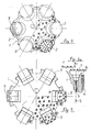
- Fig. 1 shows a drill body 1 for a hammering drill which drills by means of its drilling surface, level L1, essentially the centre portion of the hole.
- Many smaller bits 2 have been mounted in the drill body 1 for drilling the outer circle of the hole.
- the fitting surface is curved counter surface 7 whose curvature can also be radius R.
- the bit 2 drills a hole whose diameter is little larger than the casing tube 4 needs in order to be able to follow with in a hole.
- the bit 2 is rotation piece in relation to its axis, that's why it can be rotate in its counter cavity 7.
- the bit 2 can be mounted in the drill body 1 by using as a help a separate bushing 5 which is placed into a hole drilled in the drill body 1. It is easier to machine in this kind of bushing 5 the needed counter cavities 7 as for example in the drill body 1.
- a separate bushing 5 which is placed into a hole drilled in the drill body 1. It is easier to machine in this kind of bushing 5 the needed counter cavities 7 as for example in the drill body 1.
- the mounting of the bit 2, 2' into the counter cavity and the axial direction S which describes this in figures forms with the drilling direction preferably an angle ⁇ .
- the direction S of the counter cavity deviates so advantageously outwards from the drilling direction.
- the angle ⁇ is advantageously between 0 - 30°.
- the axial direction of the counter cavity can possible be same as the drilling direction, as it is in the figure 5a . It facilitates a little the construction of the drill unit if the angle ⁇ is larger than 0.
- the figure 3 presents, how the bit 2 of the bit assembly according to the invention moves to the side at the casing tube 4, when the whole drill unit is pulled out from the hole.
- the material of the arm 6 fixing the bit 2 has been elected so that it allows the bit 2 to move out and to the side a needed distance.
- the form of the counter surface 7 causes that the bit also glides and turns inwards and doesn't at all move out in the direction S of the axis of the counter cavity.
- the casing tube 4 carries out the moving of the bit 2. When the whole drilling unit has been received out from the casing tube the bit 2 will move back into its counter cavity.
- the fixing arm 6 is for example spring-like and therefore stretchy and it is needed that it will bend at least in one point.
- the fixing arm 6 can be manufactured of pull resistant materials totally or combined, wherein it can comprise separately a stretchy portion and separately bending portion. Rubbers, plastics, fibre materials, steel springs or similar can become in question.
- the bending of the fixing arm can also be solved by means of articulated joint. In the drilling situation the fixing arm 6 stresses the bit 2, 3 against the counter cavity. The fixing arm 6 and possible holder part 8 will preferable rotate with when the bit 2 rotates.
- the bit 3 has angular form, wherein it doesn't rotate in its counter cavity.
- the moving of the bit 3 out of the cavity pushed by the casing tube 4 can, however, happen just in the same way as presented in figures 2 and 3 i.e. based on the curved or step-like side form.
- the bits 3 have always the same portion in the drilling phase, wherein they will wear a little sooner than the bits 2.
- the changing of the bits 2 and 3 takes, however, quite short time when the drill body 1 has been removed from the hole.
- the bit assembly according to the invention becomes the cheaper the larger holes are drilled.
- the centre bit will have long duration and smaller strain than one full-sized centre bit will have when drilled the whole hole only by that one bit.
- the hammer device can be smaller of its power when the summarized bit surface area doesn't correspond the drilling surface of the whole drilling.
- the drilling of the hole naturally takes little more time carried out by the way according to the invention compared with drilling by means of one bit by using heavy hammer device which is needed.
- FIG 5a there is a section view of the unrotatable bit 3 where the bit 3 locates in its counter cavity.
- the axial direction S of the counter cavity is same as the drilling direction.
Landscapes
- Engineering & Computer Science (AREA)
- Geology (AREA)
- Mining & Mineral Resources (AREA)
- Life Sciences & Earth Sciences (AREA)
- General Life Sciences & Earth Sciences (AREA)
- Fluid Mechanics (AREA)
- Environmental & Geological Engineering (AREA)
- Physics & Mathematics (AREA)
- Geochemistry & Mineralogy (AREA)
- Mechanical Engineering (AREA)
- Earth Drilling (AREA)
- Drilling Tools (AREA)
- Processing Of Stones Or Stones Resemblance Materials (AREA)
- Perforating, Stamping-Out Or Severing By Means Other Than Cutting (AREA)
- Percussive Tools And Related Accessories (AREA)
- Drilling And Exploitation, And Mining Machines And Methods (AREA)
Claims (10)
- Bohrmeißelanordnung für eine Bohrvorrichtung, die mittels Stoßwirkung und Rotation arbeitet und in welcher Bohrmeißelanordnung der Rahmen (1) der Bohrvorrichtung wenigstens teilweise in Schutzrohr (4) liegt, und an die Bohrvorrichtung wesentlich in den mittleren Teil des Bohrlochs gebracht ist, und der Rahmen (1) der Bohrvorrichtung auf einen oder mehreren stoßenden Bohrkronen (2),(3) arrangiert ist, um den Außenkreis des Bohrlochs zu bohren, und die erwähnten Bohrkronen (2),(3), die den Außenkreis des Lochs bohren sind arrangiert die Bohrfläche zu bohren, die in Bohrrichtung mehr nach hinten liegt als für den Rahmen (1) der Bohrvorrichtung beabsichtigte Bohrfläche (L1), und weiter dass die erwähnten Bohrkronen (2),(3) in Rahmen (1) der Bohrvorrichtung bildeten Anschlag-hohlräume (7) arrangiert sind, deren Achsenrichtungen (S) entweder in gleicher - oder in Bohrrichtung sind, oder von der Richtung auswärts abweichen gekennzeichnet daraus, dass die erwähnten in Anschlaghohlräumen (7) montierten Bohrkronen (2),(3) mit Hilfe von Kräften, die Resultat des Kontakts mit Schutzrohr (4) sind, wenigsten ein Teil ihrer Strecke heraus in einer Richtung, die von der Achsenrichtung (S) des Anschlaghohlraums (7) abweichen können um den Außendurchmesser der Bohreinheit kleiner zu machen
- Bohrmeißelanordnung nach Anspruch 1 gekennzeichnet daraus, dass Bohrkrone (2), angepasst in Anschlaghohlraum (7), ein Rotationsstück ist, wobei sie beabsichtigt ist beim Bohren in ihrem Anschlaghohlraum (7) zu rotieren.
- Bohrmeißelanordnung nach Anspruch 1 gekennzeichnet daraus, dass Bohrkrone (3) vom Rotationsstück abweicht und beabsichtigt ist, in ihrem Anschlaghohlraum rotationsfrei zu sein.
- Bohrmeißelanordnung nach Anspruch 1 gekennzeichnet daraus, dass Bohrkrone (2), die den Außenkreis des Lochs bohrt, wesentlich nur mit einem Teil (9) ihrer Stirnfläche zu bohren, angepasst ist, wobei die ganze Rotation der Bohrmeißelanordnung während Bohren auch die erwähnte Bohrkrone (2) um ihre eigene Achse dreht.
- Bohrmeißelanordnung nach Anspruch 1 gekennzeichnet daraus, dass Bohrkrone (2), (3) aus von ihrem Anschlagshohlraum (7) weg gerückt werden kann, damit sie ganz und gar auf die inneren Fläche der Innenseite des nächsten Schutzrohrs (4) der Bohrmeißelanordnung weggerückt werden kann, wobei es möglich ist, die Bohrmeißelanordnung aus dem Loch zu entfernen, und Schutzrohr (4) im Loch zu lassen.
- Bohrmeißelanordnung nach Anspruch 1 gekennzeichnet daraus, dass der Der Form der Anschlagshohlraum (7) gewölbt ist wobei in Hohlraum (7) angepasste Bohrkrone (2) sich zu der Mittellinie des Rahmens der Bohrvorrichtung (1) dreht wenn Bohrkrone (2) vom Ausgangsraum heraus kommt.
- Bohrmeißelanordnung nach Anspruch 1 gekennzeichnet daraus, dass der Seitenform des Anschlagshohlraums abgestuft ist.
- Bohrmeißelanordnung nach Anspruch 1 gekennzeichnet daraus, dass die Befestigung der Bohrkrone (2), in den Anschlagsraum mit Hilfe einer Befestigungstange (6) angepasst ist, der für Bohrkrone (2),(3) nötigen Bewegungsabstand in gewünschter Richtung von der Anschlagshohlraum erlaubt.
- Bohrmeißelanordnung nach Anspruch 1 gekennzeichnet daraus, dass in Rahmen der Bohrvorrichtung, mit Hilfe einer einzelne Hülse (5), der Anschlagsraum im Loch, gebohrt in den Rahmen der Bohrvorrichtung, angepasst ist.
- Bohrmeißelanordnung nach Anspruch 1 gekennzeichnet daraus, dass die Bohrkronen (2),(3), die den Außenkreis des Lochs bohren, können getauscht werden durch Abkopplung der Anordnung des Befestigungsstiels (6)(8).
Applications Claiming Priority (3)
| Application Number | Priority Date | Filing Date | Title |
|---|---|---|---|
| FI20022043A FI115245B (fi) | 2002-11-18 | 2002-11-18 | Teräsovitelma iskevään poraan |
| FI20022043 | 2002-11-18 | ||
| PCT/FI2003/000876 WO2004046496A1 (en) | 2002-11-18 | 2003-11-18 | Bit assembly for a hammering drill |
Publications (2)
| Publication Number | Publication Date |
|---|---|
| EP1579104A1 EP1579104A1 (de) | 2005-09-28 |
| EP1579104B1 true EP1579104B1 (de) | 2009-01-21 |
Family
ID=8564948
Family Applications (1)
| Application Number | Title | Priority Date | Filing Date |
|---|---|---|---|
| EP03773762A Expired - Lifetime EP1579104B1 (de) | 2002-11-18 | 2003-11-18 | Meisselanordnung für einen bohrhammer |
Country Status (10)
| Country | Link |
|---|---|
| US (1) | US7124843B2 (de) |
| EP (1) | EP1579104B1 (de) |
| JP (1) | JP4384050B2 (de) |
| CN (1) | CN100510309C (de) |
| AT (1) | ATE421630T1 (de) |
| AU (1) | AU2003282144A1 (de) |
| CA (1) | CA2506605A1 (de) |
| DE (1) | DE60326009D1 (de) |
| FI (1) | FI115245B (de) |
| WO (1) | WO2004046496A1 (de) |
Families Citing this family (1)
| Publication number | Priority date | Publication date | Assignee | Title |
|---|---|---|---|---|
| AT501696B1 (de) * | 2004-03-30 | 2008-03-15 | Alwag Tunnelausbau Gmbh | Verfahren und vorrichtung zum bohren von löchern in boden- oder gesteinsmaterial |
Family Cites Families (14)
| Publication number | Priority date | Publication date | Assignee | Title |
|---|---|---|---|---|
| US2400853A (en) * | 1941-07-08 | 1946-05-21 | Walter P Stilley | Well drilling apparatus |
| US2815932A (en) * | 1956-02-29 | 1957-12-10 | Norman E Wolfram | Retractable rock drill bit apparatus |
| GB973790A (en) * | 1962-07-17 | 1964-10-28 | Jerome Labrosse | Drill assembly |
| AT294728B (de) | 1969-05-30 | 1971-12-10 | Boehler & Co Ag Geb | Versenkhammer-Bohrgerät |
| CH622312A5 (en) * | 1977-09-30 | 1981-03-31 | Anton Broder | Drill bit, in particular for drilling in overburden |
| DE2829868A1 (de) | 1978-07-07 | 1980-01-17 | Heinrich Loth | Signierstempel |
| US4386669A (en) * | 1980-12-08 | 1983-06-07 | Evans Robert F | Drill bit with yielding support and force applying structure for abrasion cutting elements |
| US4478296A (en) * | 1981-12-14 | 1984-10-23 | Richman Jr Charles D | Drill bit having multiple drill rod impact members |
| DE3510375A1 (de) | 1985-03-22 | 1986-09-25 | Robert Bosch Gmbh, 7000 Stuttgart | Werkzeug zur herstellung hinterschnittener bohrloecher |
| US5004056A (en) * | 1988-05-23 | 1991-04-02 | Goikhman Yakov A | Percussion-rotary drilling tool |
| US4940097A (en) * | 1988-12-13 | 1990-07-10 | Martini Leo A | Fluid powered rotary percussion drill with formation disintegration inserts |
| EP0429649A1 (de) | 1989-05-19 | 1991-06-05 | Vsesojuzny Nauchno-Issledovatelsky Institut Metodiki I Tekhniki Razvedki, Nauchno-Proizvodstvennoe Obiedinenie "Geotekhnika" | Bohreinrichtung |
| FI91552C (fi) * | 1991-03-25 | 1994-07-11 | Valto Ilomaeki | Poraava laite ja sen etenemisen säätömenetelmä |
| FI95618C (fi) | 1992-12-03 | 1998-09-03 | Jorma Jaervelae | Porauslaitteisto |
-
2002
- 2002-11-18 FI FI20022043A patent/FI115245B/fi not_active IP Right Cessation
-
2003
- 2003-11-18 CN CNB2003801067441A patent/CN100510309C/zh not_active Expired - Fee Related
- 2003-11-18 DE DE60326009T patent/DE60326009D1/de not_active Expired - Lifetime
- 2003-11-18 CA CA002506605A patent/CA2506605A1/en not_active Abandoned
- 2003-11-18 AU AU2003282144A patent/AU2003282144A1/en not_active Abandoned
- 2003-11-18 US US10/535,201 patent/US7124843B2/en not_active Expired - Fee Related
- 2003-11-18 EP EP03773762A patent/EP1579104B1/de not_active Expired - Lifetime
- 2003-11-18 WO PCT/FI2003/000876 patent/WO2004046496A1/en not_active Ceased
- 2003-11-18 JP JP2004552757A patent/JP4384050B2/ja not_active Expired - Fee Related
- 2003-11-18 AT AT03773762T patent/ATE421630T1/de not_active IP Right Cessation
Also Published As
| Publication number | Publication date |
|---|---|
| ATE421630T1 (de) | 2009-02-15 |
| FI20022043L (fi) | 2004-05-19 |
| FI115245B (fi) | 2005-03-31 |
| WO2004046496A1 (en) | 2004-06-03 |
| US20060054362A1 (en) | 2006-03-16 |
| DE60326009D1 (de) | 2009-03-12 |
| EP1579104A1 (de) | 2005-09-28 |
| CN1729344A (zh) | 2006-02-01 |
| CA2506605A1 (en) | 2004-06-03 |
| JP2006506565A (ja) | 2006-02-23 |
| CN100510309C (zh) | 2009-07-08 |
| AU2003282144A1 (en) | 2004-06-15 |
| FI20022043A0 (fi) | 2002-11-18 |
| US7124843B2 (en) | 2006-10-24 |
| JP4384050B2 (ja) | 2009-12-16 |
Similar Documents
| Publication | Publication Date | Title |
|---|---|---|
| US8550180B2 (en) | Bearing of a breaking device tool | |
| AU2023206186B2 (en) | Cutting device with tapered cutting element | |
| AU2011304382B2 (en) | A rock drill bit for percussive drilling and a rock drill bit button | |
| EP2787163B1 (de) | Ausgrabungswerkzeug | |
| CN113027448B (zh) | 具有多个切削头的采矿机械 | |
| EP2201180B1 (de) | Vibrationszange | |
| US20060054362A1 (en) | Bit assembly for a hammering drill | |
| AU2019309886B2 (en) | Rock cutting assembly | |
| IE78441B1 (en) | Drill tool | |
| US7454851B1 (en) | Cylindrical cutting element supported on a drum | |
| GB2402146A (en) | Drilling tool | |
| US12540548B2 (en) | Cutting device and support for same | |
| EP1463869B1 (de) | Mitnehmer | |
| CN105604488A (zh) | 一种截齿型钻头 | |
| EP4431695B1 (de) | Schafthülsenanordnung, gesteinsbohrmaschine und verfahren | |
| KR100302077B1 (ko) | 암반굴착용비트 | |
| JPH09303087A (ja) | ローラビット取付具 |
Legal Events
| Date | Code | Title | Description |
|---|---|---|---|
| PUAI | Public reference made under article 153(3) epc to a published international application that has entered the european phase |
Free format text: ORIGINAL CODE: 0009012 |
|
| 17P | Request for examination filed |
Effective date: 20050617 |
|
| AK | Designated contracting states |
Kind code of ref document: A1 Designated state(s): AT BE BG CH CY CZ DE DK EE ES FI FR GB GR HU IE IT LI LU MC NL PT RO SE SI SK TR |
|
| AX | Request for extension of the european patent |
Extension state: AL LT LV MK |
|
| DAX | Request for extension of the european patent (deleted) | ||
| 17Q | First examination report despatched |
Effective date: 20061220 |
|
| GRAP | Despatch of communication of intention to grant a patent |
Free format text: ORIGINAL CODE: EPIDOSNIGR1 |
|
| GRAS | Grant fee paid |
Free format text: ORIGINAL CODE: EPIDOSNIGR3 |
|
| GRAA | (expected) grant |
Free format text: ORIGINAL CODE: 0009210 |
|
| AK | Designated contracting states |
Kind code of ref document: B1 Designated state(s): AT BE BG CH CY CZ DE DK EE ES FI FR GB GR HU IE IT LI LU MC NL PT RO SE SI SK TR |
|
| REG | Reference to a national code |
Ref country code: GB Ref legal event code: FG4D |
|
| REG | Reference to a national code |
Ref country code: CH Ref legal event code: EP |
|
| REG | Reference to a national code |
Ref country code: IE Ref legal event code: FG4D |
|
| REF | Corresponds to: |
Ref document number: 60326009 Country of ref document: DE Date of ref document: 20090312 Kind code of ref document: P |
|
| REG | Reference to a national code |
Ref country code: SE Ref legal event code: TRGR |
|
| PG25 | Lapsed in a contracting state [announced via postgrant information from national office to epo] |
Ref country code: NL Free format text: LAPSE BECAUSE OF FAILURE TO SUBMIT A TRANSLATION OF THE DESCRIPTION OR TO PAY THE FEE WITHIN THE PRESCRIBED TIME-LIMIT Effective date: 20090121 |
|
| NLV1 | Nl: lapsed or annulled due to failure to fulfill the requirements of art. 29p and 29m of the patents act | ||
| PG25 | Lapsed in a contracting state [announced via postgrant information from national office to epo] |
Ref country code: ES Free format text: LAPSE BECAUSE OF FAILURE TO SUBMIT A TRANSLATION OF THE DESCRIPTION OR TO PAY THE FEE WITHIN THE PRESCRIBED TIME-LIMIT Effective date: 20090502 Ref country code: FI Free format text: LAPSE BECAUSE OF FAILURE TO SUBMIT A TRANSLATION OF THE DESCRIPTION OR TO PAY THE FEE WITHIN THE PRESCRIBED TIME-LIMIT Effective date: 20090121 Ref country code: SI Free format text: LAPSE BECAUSE OF FAILURE TO SUBMIT A TRANSLATION OF THE DESCRIPTION OR TO PAY THE FEE WITHIN THE PRESCRIBED TIME-LIMIT Effective date: 20090121 |
|
| PG25 | Lapsed in a contracting state [announced via postgrant information from national office to epo] |
Ref country code: PT Free format text: LAPSE BECAUSE OF FAILURE TO SUBMIT A TRANSLATION OF THE DESCRIPTION OR TO PAY THE FEE WITHIN THE PRESCRIBED TIME-LIMIT Effective date: 20090622 Ref country code: AT Free format text: LAPSE BECAUSE OF FAILURE TO SUBMIT A TRANSLATION OF THE DESCRIPTION OR TO PAY THE FEE WITHIN THE PRESCRIBED TIME-LIMIT Effective date: 20090121 |
|
| PG25 | Lapsed in a contracting state [announced via postgrant information from national office to epo] |
Ref country code: BE Free format text: LAPSE BECAUSE OF FAILURE TO SUBMIT A TRANSLATION OF THE DESCRIPTION OR TO PAY THE FEE WITHIN THE PRESCRIBED TIME-LIMIT Effective date: 20090121 |
|
| PG25 | Lapsed in a contracting state [announced via postgrant information from national office to epo] |
Ref country code: EE Free format text: LAPSE BECAUSE OF FAILURE TO SUBMIT A TRANSLATION OF THE DESCRIPTION OR TO PAY THE FEE WITHIN THE PRESCRIBED TIME-LIMIT Effective date: 20090121 Ref country code: DK Free format text: LAPSE BECAUSE OF FAILURE TO SUBMIT A TRANSLATION OF THE DESCRIPTION OR TO PAY THE FEE WITHIN THE PRESCRIBED TIME-LIMIT Effective date: 20090121 Ref country code: CZ Free format text: LAPSE BECAUSE OF FAILURE TO SUBMIT A TRANSLATION OF THE DESCRIPTION OR TO PAY THE FEE WITHIN THE PRESCRIBED TIME-LIMIT Effective date: 20090121 |
|
| PLBE | No opposition filed within time limit |
Free format text: ORIGINAL CODE: 0009261 |
|
| STAA | Information on the status of an ep patent application or granted ep patent |
Free format text: STATUS: NO OPPOSITION FILED WITHIN TIME LIMIT |
|
| PG25 | Lapsed in a contracting state [announced via postgrant information from national office to epo] |
Ref country code: SK Free format text: LAPSE BECAUSE OF FAILURE TO SUBMIT A TRANSLATION OF THE DESCRIPTION OR TO PAY THE FEE WITHIN THE PRESCRIBED TIME-LIMIT Effective date: 20090121 Ref country code: RO Free format text: LAPSE BECAUSE OF FAILURE TO SUBMIT A TRANSLATION OF THE DESCRIPTION OR TO PAY THE FEE WITHIN THE PRESCRIBED TIME-LIMIT Effective date: 20090121 |
|
| 26N | No opposition filed |
Effective date: 20091022 |
|
| PG25 | Lapsed in a contracting state [announced via postgrant information from national office to epo] |
Ref country code: BG Free format text: LAPSE BECAUSE OF FAILURE TO SUBMIT A TRANSLATION OF THE DESCRIPTION OR TO PAY THE FEE WITHIN THE PRESCRIBED TIME-LIMIT Effective date: 20090421 |
|
| PG25 | Lapsed in a contracting state [announced via postgrant information from national office to epo] |
Ref country code: MC Free format text: LAPSE BECAUSE OF NON-PAYMENT OF DUE FEES Effective date: 20091130 |
|
| REG | Reference to a national code |
Ref country code: CH Ref legal event code: PL |
|
| REG | Reference to a national code |
Ref country code: IE Ref legal event code: MM4A |
|
| PG25 | Lapsed in a contracting state [announced via postgrant information from national office to epo] |
Ref country code: GR Free format text: LAPSE BECAUSE OF FAILURE TO SUBMIT A TRANSLATION OF THE DESCRIPTION OR TO PAY THE FEE WITHIN THE PRESCRIBED TIME-LIMIT Effective date: 20090422 Ref country code: LI Free format text: LAPSE BECAUSE OF NON-PAYMENT OF DUE FEES Effective date: 20091130 Ref country code: IE Free format text: LAPSE BECAUSE OF NON-PAYMENT OF DUE FEES Effective date: 20091118 Ref country code: CH Free format text: LAPSE BECAUSE OF NON-PAYMENT OF DUE FEES Effective date: 20091130 |
|
| PG25 | Lapsed in a contracting state [announced via postgrant information from national office to epo] |
Ref country code: IT Free format text: LAPSE BECAUSE OF NON-PAYMENT OF DUE FEES Effective date: 20091118 |
|
| PG25 | Lapsed in a contracting state [announced via postgrant information from national office to epo] |
Ref country code: LU Free format text: LAPSE BECAUSE OF NON-PAYMENT OF DUE FEES Effective date: 20091118 |
|
| PG25 | Lapsed in a contracting state [announced via postgrant information from national office to epo] |
Ref country code: HU Free format text: LAPSE BECAUSE OF FAILURE TO SUBMIT A TRANSLATION OF THE DESCRIPTION OR TO PAY THE FEE WITHIN THE PRESCRIBED TIME-LIMIT Effective date: 20090722 |
|
| PGFP | Annual fee paid to national office [announced via postgrant information from national office to epo] |
Ref country code: GB Payment date: 20110301 Year of fee payment: 8 |
|
| PGRI | Patent reinstated in contracting state [announced from national office to epo] |
Ref country code: IT Effective date: 20110616 |
|
| PG25 | Lapsed in a contracting state [announced via postgrant information from national office to epo] |
Ref country code: TR Free format text: LAPSE BECAUSE OF FAILURE TO SUBMIT A TRANSLATION OF THE DESCRIPTION OR TO PAY THE FEE WITHIN THE PRESCRIBED TIME-LIMIT Effective date: 20090121 |
|
| PG25 | Lapsed in a contracting state [announced via postgrant information from national office to epo] |
Ref country code: CY Free format text: LAPSE BECAUSE OF FAILURE TO SUBMIT A TRANSLATION OF THE DESCRIPTION OR TO PAY THE FEE WITHIN THE PRESCRIBED TIME-LIMIT Effective date: 20090121 |
|
| PGFP | Annual fee paid to national office [announced via postgrant information from national office to epo] |
Ref country code: SE Payment date: 20111129 Year of fee payment: 9 Ref country code: FR Payment date: 20111215 Year of fee payment: 9 |
|
| PGFP | Annual fee paid to national office [announced via postgrant information from national office to epo] |
Ref country code: DE Payment date: 20120127 Year of fee payment: 9 |
|
| PGFP | Annual fee paid to national office [announced via postgrant information from national office to epo] |
Ref country code: IT Payment date: 20121123 Year of fee payment: 10 |
|
| GBPC | Gb: european patent ceased through non-payment of renewal fee |
Effective date: 20121118 |
|
| PG25 | Lapsed in a contracting state [announced via postgrant information from national office to epo] |
Ref country code: SE Free format text: LAPSE BECAUSE OF NON-PAYMENT OF DUE FEES Effective date: 20121119 |
|
| REG | Reference to a national code |
Ref country code: FR Ref legal event code: ST Effective date: 20130731 |
|
| REG | Reference to a national code |
Ref country code: DE Ref legal event code: R119 Ref document number: 60326009 Country of ref document: DE Effective date: 20130601 |
|
| PG25 | Lapsed in a contracting state [announced via postgrant information from national office to epo] |
Ref country code: DE Free format text: LAPSE BECAUSE OF NON-PAYMENT OF DUE FEES Effective date: 20130601 |
|
| PG25 | Lapsed in a contracting state [announced via postgrant information from national office to epo] |
Ref country code: FR Free format text: LAPSE BECAUSE OF NON-PAYMENT OF DUE FEES Effective date: 20121130 Ref country code: GB Free format text: LAPSE BECAUSE OF NON-PAYMENT OF DUE FEES Effective date: 20121118 |
|
| PG25 | Lapsed in a contracting state [announced via postgrant information from national office to epo] |
Ref country code: IT Free format text: LAPSE BECAUSE OF NON-PAYMENT OF DUE FEES Effective date: 20131118 |