EP1578288B1 - Vorrichtung zum festhalten eines verbindungsstabes in einem knochenankerelement eines wirbelsäulenimplantats - Google Patents
Vorrichtung zum festhalten eines verbindungsstabes in einem knochenankerelement eines wirbelsäulenimplantats Download PDFInfo
- Publication number
- EP1578288B1 EP1578288B1 EP03778390A EP03778390A EP1578288B1 EP 1578288 B1 EP1578288 B1 EP 1578288B1 EP 03778390 A EP03778390 A EP 03778390A EP 03778390 A EP03778390 A EP 03778390A EP 1578288 B1 EP1578288 B1 EP 1578288B1
- Authority
- EP
- European Patent Office
- Prior art keywords
- profile
- immobilization device
- face
- seat
- tooth
- Prior art date
- Legal status (The legal status is an assumption and is not a legal conclusion. Google has not performed a legal analysis and makes no representation as to the accuracy of the status listed.)
- Expired - Lifetime
Links
- 238000004873 anchoring Methods 0.000 title claims abstract description 84
- 239000007943 implant Substances 0.000 title claims abstract description 15
- 210000000988 bone and bone Anatomy 0.000 title description 48
- 230000000903 blocking effect Effects 0.000 claims abstract description 33
- 230000003100 immobilizing effect Effects 0.000 claims abstract description 29
- 230000005489 elastic deformation Effects 0.000 description 6
- 230000014759 maintenance of location Effects 0.000 description 6
- 238000006073 displacement reaction Methods 0.000 description 3
- 230000000295 complement effect Effects 0.000 description 2
- 238000009434 installation Methods 0.000 description 2
- 238000003780 insertion Methods 0.000 description 1
- 230000037431 insertion Effects 0.000 description 1
- 230000000717 retained effect Effects 0.000 description 1
Images


Classifications
-
- A—HUMAN NECESSITIES
- A61—MEDICAL OR VETERINARY SCIENCE; HYGIENE
- A61B—DIAGNOSIS; SURGERY; IDENTIFICATION
- A61B17/00—Surgical instruments, devices or methods
- A61B17/56—Surgical instruments or methods for treatment of bones or joints; Devices specially adapted therefor
- A61B17/58—Surgical instruments or methods for treatment of bones or joints; Devices specially adapted therefor for osteosynthesis, e.g. bone plates, screws or setting implements
- A61B17/68—Internal fixation devices, including fasteners and spinal fixators, even if a part thereof projects from the skin
- A61B17/70—Spinal positioners or stabilisers, e.g. stabilisers comprising fluid filler in an implant
- A61B17/7001—Screws or hooks combined with longitudinal elements which do not contact vertebrae
- A61B17/7032—Screws or hooks with U-shaped head or back through which longitudinal rods pass
-
- A—HUMAN NECESSITIES
- A61—MEDICAL OR VETERINARY SCIENCE; HYGIENE
- A61B—DIAGNOSIS; SURGERY; IDENTIFICATION
- A61B17/00—Surgical instruments, devices or methods
- A61B17/56—Surgical instruments or methods for treatment of bones or joints; Devices specially adapted therefor
- A61B17/58—Surgical instruments or methods for treatment of bones or joints; Devices specially adapted therefor for osteosynthesis, e.g. bone plates, screws or setting implements
- A61B17/68—Internal fixation devices, including fasteners and spinal fixators, even if a part thereof projects from the skin
- A61B17/70—Spinal positioners or stabilisers, e.g. stabilisers comprising fluid filler in an implant
-
- A—HUMAN NECESSITIES
- A61—MEDICAL OR VETERINARY SCIENCE; HYGIENE
- A61B—DIAGNOSIS; SURGERY; IDENTIFICATION
- A61B17/00—Surgical instruments, devices or methods
- A61B17/56—Surgical instruments or methods for treatment of bones or joints; Devices specially adapted therefor
-
- A—HUMAN NECESSITIES
- A61—MEDICAL OR VETERINARY SCIENCE; HYGIENE
- A61B—DIAGNOSIS; SURGERY; IDENTIFICATION
- A61B17/00—Surgical instruments, devices or methods
- A61B17/56—Surgical instruments or methods for treatment of bones or joints; Devices specially adapted therefor
- A61B17/58—Surgical instruments or methods for treatment of bones or joints; Devices specially adapted therefor for osteosynthesis, e.g. bone plates, screws or setting implements
Definitions
- the present invention relates to a device for immobilizing a connecting rod in a bone anchoring element of a spinal implant.
- EP-A-1 064 885 discloses a device for immobilizing a connecting rod of a bone anchoring element according to the preamble of claim 1.
- the purpose of the immobilization device according to the present invention is to improve the retention of the locking element on the bone anchoring element, while preserving independent fastenings for retaining, on the one hand, the connecting rod and other of the blocking element.
- the immobilizing device comprises a bone anchoring element comprising retaining means able to deform elastically under a thrust force F and a locking element comprising on the one hand lugs which cooperate with the retained to allow attachment of the locking element on the bone anchoring element and secondly, a clamping screw for immobilization in rotation and in translation of the connecting rod between the anchoring element bone and the blocking element.
- the immobilizing device comprises a bone anchoring element whose central face of each vertical wall is pierced with a hole opening into the central opening U-shaped.
- the immobilizing device comprises a bone anchoring element whose elastic blades of the head respectively comprise in their upper part a tooth whose external profile is curved and inclined.
- the immobilizer according to the present invention comprises a locking element whose lower face comprises, in a direction parallel to the axis XX 'of the connecting rod, a housing having a profile in cylinder portion.
- the immobilizer according to the present invention comprises a locking element whose upper face, opposite to the lower one, comprises in its middle a threaded bore opening into the housing and in which a clamping screw cooperates.
- the immobilizing device comprises a locking element which has a first pair of opposite lateral faces respectively comprising, above the housing, a recess intended to cooperate with an instrument for the manipulation and positioning of said locking element on the bone anchoring element.
- the immobilizing device comprises a locking element which has a second pair of opposite lateral faces which are each integral with two lugs arranged in the width of said locking element and positioned in the extension of the first pair of lateral faces. .
- the immobilizing device comprises a locking element each lug comprises respectively in its upper part an inclined pan or chamfer whose lower base is positioned in the plane containing each of said first pairs of side faces.
- the immobilizer according to the present invention comprises a locking element, each lug comprises respectively in its lower part and opposite inclined faces, a rounded profile.
- the immobilizing device comprises a locking element whose distance d separating two lugs is less than that provided between two teeth of the same vertical wall of the bone anchoring element.
- the immobilizing device comprises a head comprising two vertical walls with a truncated profile disposed opposite each other and in parallel planes in order to define a first central U-shaped opening carried by the axis.
- the immobilizing device comprises a head comprising two perpendicular openings which make it possible to define at each angle of the head resilient blades that can deform elastically under a thrust force F.
- the immobilizing device comprises a head provided with elastic blades respectively comprising in their upper part a tooth whose hooking profile is turned towards the inside of the second opening and above the central face. of each vertical wall.
- the immobilizing device comprises a head of which each tooth comprises, above its attachment portion and in the direction of the opening, an inclined external profile extending towards the outside by a curved profile. .
- the immobilizing device comprises a locking element comprising a lower face comprising in a direction parallel to the axis XX 'a housing having a profile in a portion of a cylinder in order to cooperate with the connecting rod, an upper surface comprising in its middle a threaded bore opening into the housing and in which a clamping screw cooperates, and side faces parallel in pairs and at least two of which are secured respectively to two tooth-shaped lugs.
- the immobilizer according to the present invention comprises a locking element, each lug comprises a latching portion positioned at a distance and at a distance d1 from the lateral and opposite faces of the locking element.
- the immobilizing device comprises a head whose elastic blades respectively comprise in their upper part a tooth whose hooking profile is turned towards the interior of the central opening.
- the immobilizing device comprises a head of which each tooth comprises above its attachment portion and towards the opening an inclined outer profile extending towards the outside by a curved profile.
- the immobilizing device comprises a locking element comprising a lower face comprising, in a direction parallel to the axis XX ', a housing having a profile in a portion of a cylinder in order to cooperate with the connecting rod, a upper face comprising in its center a threaded bore opening into the housing and in which cooperates a clamping screw and parallel side faces in pairs and at least two of which are integral respectively with two tooth-shaped lugs.
- the immobilizer according to the present invention comprises a locking element, each side face disposed in a plane parallel to the axis XX 'of the housing comprises two tooth-shaped lugs separated by a vertical rib having a vertical central housing.
- the immobilizing device comprises a locking element whose attachment portions of the lugs are closed opposite the side faces through the corresponding vertical rib.
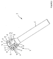
- FIG. 1 shows a device 1 for immobilizing a spinal implant 4 for locking in rotation and in translation of a connecting rod 2 at the level of each instrumented vertebra of a vertebral column.
- the immobilizing device 1 consists of a bone anchoring element 3 and a locking element 5 intended to cooperate with the anchoring element 3 for fixing in rotation and in translation of the connecting rod 2 .
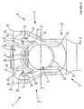
- FIG. 2 shows the bone anchoring element 3 comprising an anchoring part 6 and a receiving part 7.
- the anchoring part 6 can have either the shape of a hook or a fixed threaded profile or not of the receiving part 7 to be fixed on / or in the vertebral body of the vertebra to be instrumented.
- the receiving part 7 consists of a U-shaped head 8 open in its upper part 7 in order to cooperate with the connecting rod 2 and the locking element 5.
- the head 8 has two vertical walls 9, 10 arranged opposite each other and in parallel planes to define a central opening 11 in the shape of a U whose bottom 12 has a profile in cylinder portion.
- Each vertical wall 9, 10 consists of a central face 13 bordered laterally and on each side by elastic strips 14, 15 respectively separated from said central face by vertical slots 16, 17.
- each vertical wall 9, 10 is pierced with a hole 18 opening into the central opening 11 in the shape of a U.
- the elastic blades 14, 15 of the head 8 respectively comprise in their upper part a tooth 19, 20 whose outer profile 21, 22 is curved and inclined towards the outside of each vertical wall 9, 10.
- FIG. 3 shows the blocking element 5 of the immobilizing device 1 which has a substantially parallelepipedal external profile, each of the opposite faces 23, 24 of which; 25, 26, 27 and 28 are parallel in pairs.
- the lower face 24 of the locking element 5 comprises in a direction parallel to the axis XX 'of the connecting rod 2 a housing 29 having a profile portion of a cylinder.
- the upper face 23 of the locking element 5 comprises in its center a threaded bore 30 opening into the housing 29 and in which a clamping screw 31 cooperates.
- the first pair of lateral faces 25, 26 of the locking element 5 respectively comprises, above the housing 29, an impression 32 intended to cooperate with the teeth of an instrument, not shown, allowing the manipulation and the positioning of said element. locking on the bone anchoring element 3.
- the second pairs of lateral faces 27, 28 of the locking element 5 are each integral with two lugs 33, 34 arranged in the width of said locking element or in the extension of each lateral face 25, 26.
- the locking element 5 comprises four lugs 33, 34 extend towards the outside of the latter and in a direction perpendicular to the plane containing each lateral face 27, 28.
- Each lug 33, 34 respectively comprises in its upper part an inclined or chamfered portion 35, 36 directed towards the lateral faces 25, 26 so that the lower base of each inclined face 35, 36 is in the plane containing each of said lateral faces. 25, 26.
- Each lug 33, 34 has respectively in its lower part and on the opposite inclined faces 35, 36 a rounded profile 37, 38 for sliding said lugs on the teeth 19, 20 during assembly of the locking element 5 with the bone anchoring element 3.
- the distance d provided between two lugs 33, 34 of the same lateral face 27, 28 is smaller than that provided between two teeth 19, 20 of the same vertical wall 9, 10 of the head 8 of the anchoring element. bone 3.
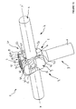
- FIGS. 4 and 5 illustrate the introduction and the retention of the locking element 5 on the head 8 of the anchoring element 3 in order to be able to lock in rotation and in translation the connecting rod 2 in each immobilization device 1 anchored to the vertebral body of a vertebra.
- the bone anchoring element 3 is fixed or hooked depending on its structure to the vertebral body of a vertebra to be instrumented.
- the connecting rod 2 is positioned inside the central opening 11 of the head 8 of the bone anchoring element 3.
- the locking element 5 is positioned above the head 8 of the bone anchoring element 3 so that the lugs 33, 34 of the same lateral face 27, 28 bear against the corresponding teeth 19, 20 of the same vertical wall 9, 10.
- a thrust force F is applied using an instrument, not shown, on the locking element 5 so that the lugs 33, 34 of each lateral face 27, 28 laterally deforms the elastic blades 14, 15 of each wall 9, 10 of the head 8 of the bone anchoring element 3.
- the elastic deformation of the blades 14, 15 is effected in the direction of the central face 13 of each vertical wall 9, 10 of the head 8 because of the difference in width provided between the lugs 33, 34 and the teeth 19, 20 ( Figure 4).
- each lug 33, 34 has a lower part with a rounded profile 37, 38 which slides on the curved outer profile 21, 22 of each tooth 19, 20 integral with the blades. 14, 15.
- the thrust force F must be sufficient for each lug 33, 34 to engage with the corresponding tooth 19, 20 of the elastic blades 14, 15.
- the retention of the lugs 33, 34 is obtained when each inclined section 35, 36 cooperates with the profile of the tooth 19, 20 corresponding ( Figure 5).
- the retention of the lugs 33, 34 is obtained by the elasticity of the blades 14, 15 which return to the rest position after the passage of the lugs 33, 34 on the teeth 19, 20 corresponding.
- the connecting rod 2 is then immobilized in rotation and in translation through the clamping screw 31 which is screwed inside the bore 30 of the locking element 5.
- the clamping screw 31 under the tightening force, comes to block the connecting rod 2 against the bottom 12 in cylinder portion of the central opening 11 of the head 8 of the anchoring element 3.
- the clamping force of the pressure screw 31 against the connecting rod 2 allows, by means of a vertical displacement directed in a direction opposite to that of said rod, to block the locking element 5 in the head 8 of the anchoring element 3.
- FIGS. 6 to 10 show a first variant of the spinal implant and more particularly the immobilization device 1 for locking in rotation and in translation of the connecting rod 2 at the level of each instrumented vertebra of a spinal column. .
- the immobilizing device 1 consists of a bone anchoring element 3 and a locking element 5 intended to cooperate with the anchoring element 3 for fixing in rotation and in translation of the connecting rod 2 .
- FIG. 7 shows the bone anchoring element 3 comprising an anchoring part 6 and a receiving part 7.
- the anchoring part 6 may have either the shape of a hook or a fixed threaded profile or not of the receiving part 7 to be fixed on / or in the vertebral body of the vertebra to be instrumented.
- the receiving part 7 consists of a U-shaped head 8, open in its upper part to be able to cooperate with the connecting rod 2 and the locking element 5.
- the head 8 comprises two vertical walls 9, 10 with a truncated profile, arranged opposite each other and in parallel planes in order to define a first central opening 11 in the shape of a U carried by the axis XX 'of the connecting rod 2 and whose bottom 12 has a profile in cylinder portion and a second opening 39 perpendicular to the axis XX 'and the first opening 11.
- the two perpendicular openings 11 and 39 define at each angle of the head 8 retaining means 14, 15 may deform elastically under a thrust F.
- Each truncated vertical wall 9, 10 consists of a central face 13 whose height is delimited by the second opening 39 passing through the head 8 of the receiving part 7.
- Each central face 13 is bordered laterally and on each side by elastic strips 14, 15 respectively separated from said central face by vertical slots 16, 17.
- each truncated vertical wall 9, 10 is pierced with a non-through hole 18 allowing an instrumentation to hang on to allow the insertion of the locking element 5 into the anchoring element 3 .
- the elastic blades 14, 15 of the head 8 respectively comprise in their upper part a tooth 19, 20 whose attachment profile 40, 41 is turned towards the inside of the second opening 39 and above the face. central 13 of each vertical wall 9, 10.
- Each tooth 19, 20 has above its attachment portion 40, 41 and towards the opening 39 an inclined outer profile 42, 43 extending towards the outside of each blade 14, 15 by a profile curved 44, 45.
- FIG. 8 shows the blocking element 5 of the immobilizing device 1 which has a substantially parallelepipedal external profile, each of the opposite faces 23, 24 of which; 25, 26, 27 and 28 are parallel in pairs.
- the lower face 24 of the locking element 5 comprises, in a direction parallel to the axis XX ', a housing 29 having a profile in a portion of a cylinder in order to receive the connecting rod 2 during assembly and fixing of the immobilizer 1.
- the upper face 23 of the locking element 5 comprises in its center a threaded bore 30 opening into the housing 29 and in which a clamping screw 31 cooperates.
- the locking element 5 comprises two lugs 33 and two lugs 34 which extend towards the outside of the latter.
- Each lug 33, 34 respectively comprises a hooking portion 48, 49 delimited by an arrangement of inclined and curved profiles for cooperation with the attachment portions 40, 41 of each tooth 19, 20 during the installation of the lug. blocking element 5 in the head 8 of the anchoring element 3.
- attachment portions 48, 49 of each lug 33, 34 are positioned at a distance and at a distance d1 from the lateral and opposite sides 25, 26 of the locking element 5.
- Each lug 33, 34 has respectively an inclined outer profile 37, 38 for sliding said lugs and the spacing of the elastic blades 14, 15 to the outside of the head 8 in order to achieve the assembly of the locking element 5 with the bone anchoring element 3.
- FIGS. 9 and 10 show the different steps for assembling the blocking element 5 in the head 8 of the anchoring element 3 in order to fix the connecting rod 2 in rotation and in translation. in each immobilization device 1 anchored in the vertebral body of a vertebra.
- the bone anchoring element 3 is fixed or hooked according to its structure to a vertebra to be instrumented.
- the connecting rod 2 is positioned inside the central opening 11 of the head 8 of the bone anchoring element 3 before the introduction of the locking element 5.
- the locking element 5 is positioned above the head 8 of the bone anchoring element 3 so that the lugs 33, 34 of the same lateral face 27, 28 bear against the corresponding teeth 19, 20 of the same vertical wall 9, 10.
- a thrust force F is made in a substantially vertical direction using an instrument, not shown, on the locking element 5 so that the lugs 33, 34 of each lateral face 27, 28 laterally deform the elastic blades. 14, 15 of each wall 9, 10 of the head 8 of the bone anchoring element 3.
- the elastic deformation of the blades 14, 15 is effected in the direction of the outside of the head 8, ie in a direction which moves away from the central face 13 of each vertical wall 9, 10 of the head 8 , due to the difference in the dimensions provided between the lugs 33, 34 and the teeth 19, 20 ( Figure 9).
- each lug 33, 34 has a lower inclined profile portion 37, 38 which slides on the outer profile of each tooth 19, 20 integral with the blades 14, 15.
- the thrust force F must be sufficient for each attachment portion 48, 49 of the lugs 33, 34 to snap into engagement with the attachment portion 40, 41 of each corresponding tooth 19, 20 of the elastic blades 14, 15.
- the retention of the locking element 5 is obtained by the elasticity of the blades 14, 15 which return to the rest position after the passage of the lugs 33, 34 on the teeth 19, 20 corresponding.
- the connecting rod 2 is slidably fitted in a cylindrical groove formed by the bottom 12 having a cylindrical portion profile of the head 8 of the bone anchoring element 3 and the housing 29 having a cylindrical portion profile of the the blocking element 5.
- the connecting rod 2 is then immobilized in rotation and in translation through the clamping screw 31 which is screwed inside the bore 30 of the locking element 5.
- the clamping screw 31 under the tightening force, comes to block the connecting rod 2 against the bottom 12 in cylinder portion of the central opening 11 of the head 8 of the anchoring element 3.
- the clamping force of the pressure screw 31 against the connecting rod 2 allows, by means of a vertical displacement directed in a direction opposite to that of said rod, to block the locking element 5 in the head 8 of the anchoring element 3.
- FIGS. 11 to 18 show a second variant of the spinal implant and more particularly the immobilization device 1 for locking in rotation and in translation of a connecting rod 2 at the level of each instrumented vertebra of a column spinal.
- the immobilizing device 1 consists of a bone anchoring element 3 and a blocking element 5 intended to cooperate with the anchoring element 3 for fixing in rotation and in translation of the connecting rod 2 .
- the bone anchoring element 3 comprising an anchoring portion 6 and a receiving portion 7.
- the anchoring portion 6 can have either the shape of a hook or a threaded profile secured to the receiving part or not 7 to come to fix on / or in the vertebra to instrument.
- the receiving part 7 consists of a U-shaped head 8 open in its upper part to be able to cooperate with the connecting rod 2 and the locking element 5.
- the head 8 has two vertical walls 9, 10 arranged facing each other and in parallel planes in order to define a first central U-shaped opening 11 carried by the axis XX 'of the connecting rod 2 and whose bottom 12 has a cylinder portion profile.
- Each vertical wall 9, 10 is separated from the bottom 12 of the central opening 11 by a vertical slot 50 giving a certain elasticity to each wall in a direction YY 'perpendicular to that XX' of the connecting rod 2.
- the elastic vertical walls 9, 10 respectively comprise at each end a hook-shaped profile 14, 15 arranged facing each other and on either side of the central opening 11.
- Each elastic vertical wall 9, 10 has on its inner face and between the latching blades 14, 15 a vertical housing 51 having a profile in cylinder portion.
- the vertical housing 51 has on each side a groove 54 for guiding the locking element 5 when it is placed inside the U-shaped head 8.
- Each elastic vertical wall 9, 10 is pierced between the attachment blades 14, 15 of a hole 18 opening inside the central opening 11 allowing an instrumentation to hang on to allow the introduction of the blocking element 5 in the anchoring element 3.
- the attachment blades 14, 15 of the head 8 respectively comprise in their upper part a tooth 19, 20 whose attachment profile 40, 41 is turned towards the interior of the central opening 11.
- Each tooth 19, 20 has above its attachment portion 40, 41 an inclined outer profile 42, 43 extending towards the outside of each blade 14, 15 by a curved profile 44, 45.
- FIG. 14 shows the blocking element 5 of the immobilizing device 1 which has a substantially parallelepipedal external profile, each of the opposite faces 23, 24 of which; 25, 26, 27 and 28 are parallel in pairs.
- the lower face 24 of the blocking element 5 comprises, in a direction parallel to the axis XX ', a housing 29 having a profile in a portion of a cylinder in order to receive the connecting rod 2 during assembly and fixing of the device. of immobilization 1.
- the upper face 23 of the locking element 5 comprises in its center a threaded bore 30 opening into the housing 29 and in which a clamping screw 31 cooperates.
- Each side face 27, 28 disposed in a plane parallel to the axis XX 'of the housing 29 and perpendicular to each of the lateral faces 25, 26 of the locking element 5, comprises two lugs 33, 34 in the shape of a tooth.
- the locking element 5 comprises two lugs 33 and two lugs 34 which extend towards the outside of the latter.
- Each lug 33, 34 respectively comprises a hooking portion 48, 49 delimited by a cylinder-section profile for cooperation with the attachment portions 40, 41 of each tooth 19, 20 during the installation of the locking element 5 in the head 8 of the anchoring element 3 (FIG. 15)
- Each lug 33, 34 has respectively an inclined outer profile 37, 38 allowing the sliding of said lugs and the elastic spacing of the walls 9, 10 and thus the fastening blades 14, 15 in the direction YY 'in order to achieve the assembly of the locking element 5 with the bone anchoring element 3.
- each opposite face 27, 28 has in its middle and between the lugs 33, 34 a vertical housing 52 laterally bordered by ribs 53 for guiding the locking element 5 when it is inserted into the head 8 of the anchoring element 3.
- hooking portions 48, 49 are closed opposite the lateral faces 25, 26 via the corresponding vertical rib 53 and arranged between each lug 33, 34.
- Each vertical rib 53 may have an external profile of any shape, provided that its profile is complementary to that of the groove 54 formed in the thickness of the inner face of each vertical wall 9, 10 of the head 8 of the element d anchoring 3.
- the vertical housings 51 and 52 have a profile in complementary cylinder portion to allow the introduction of an instrument to ensure the removal of the locking element 5 of the head 8 of the anchoring element 3.
- FIGS. 15 to 18 show the various steps for assembling the blocking element 5 in the head 8 of the anchoring element 3 in order to fix in rotation and in translation the connecting rod 2 in each immobilization device 1 anchored in the vertebral body of a vertebra.
- the connecting rod 2 is positioned inside the central opening 11 of the head 8 of the bone anchoring element 3 before the introduction of the locking element 5.
- the locking element 5 is positioned above the head 8 of the bone anchoring element 3 so that the lugs 33, 34 of the same lateral face 27, 28 bear against the corresponding teeth 19, 20 of the same vertical wall 9, 10.
- a thrust force F is made in a substantially vertical direction by means of an instrument, not shown, on the locking element 5 so that the lugs 33, 34 of each lateral face 27, 28 deform laterally the vertical walls 9, 10 and thus the elastic latching blades 14, 15.
- the elastic deformation of the vertical walls 9, 10 is effected towards the outside of the head 8 because of the difference in dimensions provided between the lugs 33, 34 and the teeth 19, 20.
- each lug 33, 34 has a lower part with an inclined profile 37, 38 which slides on the external profile of each tooth 19, 20 of the attachment blades 14, 15 of each elastic wall 9, 10.
- the thrust force F must be sufficient for each latching portion 48, 49 of the lugs 33, 34 to engage with the latching portion 40, 41 of each tooth 19, 20 corresponding.
- the retention of the locking element 5 is obtained by the elasticity of the vertical walls 9, 10 and thus of the attachment blades 14, 15 which return to the rest position after the passage of the lugs 33, 34 on the teeth 19, 20 corresponding.
- the connecting rod 2 is slidably fitted in a cylindrical groove formed by the bottom 12 having a cylindrical portion profile of the head 8 of the bone anchoring element 3 and the housing 29 having a cylindrical portion profile of the the blocking element 5.
- the connecting rod 2 is then immobilized in rotation and in translation through the clamping screw 31 which is screwed inside the bore 30 of the locking element 5.
- the clamping screw 31 under the tightening force, comes to block the connecting rod 2 against the bottom 12 in cylinder portion of the central opening 11 of the head 8 of the anchoring element 3.
- the clamping force of the pressure screw 31 against the connecting rod 2 allows, by means of a vertical displacement directed in a direction opposite to that of said rod, to block the locking element 5 in the head 8 of the anchoring element 3.
- the removal of the blocking element 5 is obtained by means of an instrument which is introduced into the vertical housings 51 and 52 so as to spread the vertical walls 9, 10 towards the outside of the head 8 of the the anchoring element 3.
Landscapes
- Health & Medical Sciences (AREA)
- Orthopedic Medicine & Surgery (AREA)
- Surgery (AREA)
- Life Sciences & Earth Sciences (AREA)
- Neurology (AREA)
- Medical Informatics (AREA)
- Biomedical Technology (AREA)
- Heart & Thoracic Surgery (AREA)
- Engineering & Computer Science (AREA)
- Molecular Biology (AREA)
- Animal Behavior & Ethology (AREA)
- General Health & Medical Sciences (AREA)
- Public Health (AREA)
- Veterinary Medicine (AREA)
- Nuclear Medicine, Radiotherapy & Molecular Imaging (AREA)
- Surgical Instruments (AREA)
- Prostheses (AREA)
Claims (26)
- Vorrichtung zum Festhalten eines Verbindungsstabs (2) in einem Knochenankerelement (3) eines Wirbelsäulenimplantats (4), dadurch gekennzeichnet, dass sie einerseits ein Knochenankerelement (3) aufweist, das mit einem Kopf (8) versehen ist, der zwei senkrechte Wände (9, 10) aufweist, die eine zentrale Öffnung (11) in U-Form abgrenzen, wobei die senkrechten Wände (9, 10) Anhängklingen (14, 15) aufweisen, die sich elastisch unter einer Schubkraft F verformen können, wobei die Anhängklingen (14, 15) jeweils in ihrem oberen Teil einen Einrastzahn (19, 20) aufweisen und andererseits ein Blockierelement (5), das zwischen die elastischen Anhängklingen (14, 15) kommt, die Spannmittel (31) und Dorne (33, 34) aufweisen, die jeweils mit einem Zahn (19, 20), der fest mit den elastischen Klingen (14, 15) verbunden ist, zusammenarbeiten.
- Vorrichtung zum Festhalten nach Anspruch 1, dadurch gekennzeichnet, dass die zentrale Öffnung (11) einen Boden (12) aufweist, der ein Zylinderabschnittprofil aufweist, wobei jede elastische senkrechte Wand (9, 10) von dem Boden (12) der zentralen Öffnung (11) durch einen senkrechten Schlitz (50) getrennt ist, der jeder Wand entlang einer Richtung YY' eine bestimmte Elastizität verleiht, wobei die senkrechten elastischen Wände (9, 10) jeweils an jedem Ende ein Profil in Form einer Anhängklinge (14, 15) aufweisen, die einander gegenüberliegend und zu beiden Seiten der zentralen Öffnung (11) angeordnet sind, und dass das Blockierelement (5) eine Aufnahme (29) mit Zylinderabschnittprofil aufweist, wobei eine Gewindebohrung (30) in das Innere der Aufnahme (29) mündet, und wobei die Spannmittel eine Spannschraube (31) aufweisen, die mit der Gewindebohrung (30) zusammenwirkt.
- Vorrichtung zum Festhalten nach Anspruch 2, dadurch gekennzeichnet, dass jede senkrechte elastische Wand (9, 10) auf ihrer Innenseite und zwischen den Anhängklingen (14, 15) eine senkrechte Aufnahme (51) in Zylinderabschnitt aufweist, die an jeder Seite Rillen (54) besitzt.
- Vorrichtung zum Festhalten nach Anspruch 2, dadurch gekennzeichnet, dass die Anhängklingen (14, 15) des Kopfs (8) jeweils in ihrem oberen Teil einen Zahn (19, 20) aufweisen, dessen Anhängprofil (40, 41) zum Inneren der zentralen Öffnung (11) gekehrt ist.
- Vorrichtung zum Festhalten nach Anspruch 4, dadurch gekennzeichnet, dass jeder Zahn (19, 20) über seinem Anhängteil (40, 41) und in Richtung der Öffnung (11) ein geneigtes externes Profil (42, 43) aufweist, das sich nach außen durch ein gewölbtes Profil (44, 45) verlängert.
- Vorrichtung zum Festhalten nach Anspruch 2, dadurch gekennzeichnet, dass das Blockierelement (5) eine Innenseite (24) aufweist, die entlang einer Richtung parallel zur Achse XX' eine Aufnahme (29) aufweist, die ein Zylinderabschnittprofil aufweist, um mit dem Verbindungsschaft (2) zusammenzuwirken, wobei eine obere Seite (23) in ihrer Mitte eine Gewindebohrung (30) aufweist, die in das Innere der Aufnahme (29) mündet, und in der eine Spannschraube (31) zusammenwirkt, und seitliche Seiten (25, 26, 27, 28), die gepaart parallel sind und von welchen mindestens zwei (27, 28) jeweils fest mit zwei Dornen (33, 34) in Zahnform verbunden sind.
- Vorrichtung zum Festhalten nach Anspruch 6, dadurch gekennzeichnet, dass jede seitliche Seite (27, 28), die in einer Ebene parallel zur Achse XX' der Aufnahme (29) angeordnet ist, zwei Dorne (33, 34) in Zahnform aufweist, die Anhängteile (48, 49) aufweisen, die von einer senkrechten Aufnahme (52), die seitlich durch Rippen (53) eingefasst ist, getrennt sind.
- Vorrichtung zum Festhalten nach Anspruch 6, dadurch gekennzeichnet, dass die Anhängteile (48, 49) auf der den seitlichen Seiten (25, 26) entgegengesetzten Seite mittels der entsprechenden senkrechten Rippe (53) geschlossen sind.
- Vorrichtung zum Festhalten nach Anspruch 1, dadurch gekennzeichnet, dass die zentrale Öffnung (11) einen Boden (12) aufweist, der ein Zylinderabschnittprofil aufweist, wobei jede senkrechte Wand (9, 10) aus einer zentralen Seite (13) besteht, die seitlich und zu jeder Seite von elastischen Klingen (14, 15) eingefasst ist, die jeweils von der zentralen Seite durch senkrechte Schlitze (16, 17) getrennt sind, und dass das Blockierelement (5) eine Aufnahme (29) mit Zylinderabschnittprofil aufweist, wobei eine Gewindebohrung (30) in das Innere der Aufnahme (29) mündet, und wobei die Spannmittel eine Spannschraube (31) aufweisen, die mit der Gewindebohrung zusammenwirkt.
- Vorrichtung zum Festhalten nach Anspruch 9, dadurch gekennzeichnet, dass die zentrale Seite (13) jeder senkrechten Wand (9, 10) mit einem Loch (18) durchbohrt ist, das in das Innere der zentralen Öffnung (11) in U-Form mündet.
- Vorrichtung zum Festhalten nach Anspruch 9, dadurch gekennzeichnet, dass die elastischen Klingen (14, 15) des Kopfs (8) jeweils in ihrem oberen Teil einen Zahn (19, 20) aufweisen, dessen externes Profil (21, 22) gewölbt und geneigt ist.
- Vorrichtung zum Festhalten nach Anspruch 9, dadurch gekennzeichnet, dass das Blockierelement (5) eine untere Seite (24) aufweist, die entlang einer Richtung parallel zur Achse XX' des Verbindungsschafts (2) eine Aufnahme (29) aufweist, die ein Zylinderabschnittprofil aufweist.
- Vorrichtung zum Festhalten nach Anspruch 9, dadurch gekennzeichnet, dass das Blockierelement (5) eine obere Seite (23) der unteren Seite (24) entgegengesetzt aufweist, wobei die obere Seite (23) in ihrer Mitte eine Gewindebohrung (30) enthält, die in das Innere der Aufnahme (29) mündet, und in der eine Spannschraube (31) zusammenwirkt.
- Vorrichtung zum Festhalten nach Anspruch 9, dadurch gekennzeichnet, dass das Blockierelement (5) ein erstes Paar seitlicher entgegengesetzter Seiten (25, 26) aufweist, die jeweils über der Aufnahme (29) eine Prägung (32) aufweisen, die dazu bestimmt ist, mit einem Instrument zum Handhaben und Anbringen des Blockierelements (5) auf dem Knochenankerelement (3) zusammenzuwirken.
- Vorrichtung zum Festhalten nach Anspruch 9, dadurch gekennzeichnet, dass das Blockierelement (5) ein zweites Paar seitlicher entgegengesetzter Seiten (27, 28) aufweist, die jeweils mit zwei Dornen (33, 34), die in der Breite des Blockierelements angeordnet und in der Verlängerung jeder seitlichen Seite (25, 26) positioniert sind, fest verbunden sind.
- Vorrichtung zum Festhalten nach Anspruch 9, dadurch gekennzeichnet, dass jeder Dorn (33, 34) jeweils in seinem oberen Teil eine schiefe Ebene oder Abfasung (35, 36) aufweist, deren untere Basis in der Ebene, die jede der seitlichen Seiten (25, 26) enthält, positioniert ist.
- Vorrichtung zum Festhalten nach Anspruch 9, dadurch gekennzeichnet, dass jeder Dorn (33, 34) jeweils in seinem unteren Teil und den schiefen Ebenen (35, 36) entgegengesetzt ein gerundetes Profil (37, 38) aufweist.
- Vorrichtung zum Festhalten nach Anspruch 9, dadurch gekennzeichnet, dass die Entfernung d, die zwei Dorne (33, 34) trennt, kleiner ist als die, die zwischen den zwei Zähnen (19, 20) einer gleichen senkrechten Wand (9, 10) des Knochenankerelements (3) vorgesehen ist.
- Vorrichtung zum Festhalten nach Anspruch 9, dadurch gekennzeichnet, dass die Schubkraft F, die an das Blockierelement (5) angelegt wird, über Dorne (33, 34) und senkrechte Schlitze (16, 17) das seitliche Verformen der elastischen Klingen (14, 15) in Richtung der zentralen Seite (13) jeder Wand (9, 10) des Knochenankerelements (3) erlaubt.
- Vorrichtung zum Festhalten nach Anspruch 1, dadurch gekennzeichnet, dass sie Folgendes aufweist: ein Knochenankerelement (3), das mit einem Kopf (8) versehen ist, der zwei stumpfe senkrechte Wände (9, 10) aufweist, die eine zentrale Öffnung (11) in U-Form abgrenzen, deren Boden (12) ein Zylinderabschnittprofil aufweist, wobei jede senkrechte Wand (9, 10) aus einer zentralen Seite (13) besteht, die seitlich und auf jeder Seite durch elastische Klingen (14, 15) eingefasst ist, die jeweils von der zentralen Seite durch senkrechte Schlitze (16, 17) getrennt sind, und wobei das Blockierelement (5), das eine Aufnahme (29) mit Zylinderabschnittprofil aufweist, eine Gewindebohrung (30) aufweist, die in das Innere der Aufnahme (29) mündet, und wobei die Spannmittel eine Spannschraube (31) aufweisen, die mit der Gewindebohrung (30) zusammenwirkt, und Dorne (33, 34), die jeweils mit einem Zahn (19, 20), der fest mit den elastischen Klingen (14, 15) verbunden ist, zusammenwirken.
- Vorrichtung zum Festhalten nach Anspruch 20, dadurch gekennzeichnet, dass der Kopf (8) zwei senkrechte Wände (9, 10) mit stumpfem Profil aufweist, die einander gegenüberliegend und in parallelen Ebenen angeordnet sind, um eine erste zentrale Öffnung (11) in U-Form, die von der Achse XX' des Verbindungsschafts (2) verbunden sind, abzugrenzen, und deren Boden (12) ein Zylinderabschnittprofil aufweist, sowie eine zweite Öffnung (39) senkrecht zur Achse XX' und zu der ersten Öffnung (11).
- Vorrichtung zum Festhalten nach Anspruch 21, dadurch gekennzeichnet, dass die zwei senkrechten Öffnungen (11, 39) erlauben, an jedem Winkel des Kopfs (8) elastische Klingen (14, 15) abzugrenzen, die sich unter einer Schubkraft F elastisch verformen können.
- Vorrichtung zum Festhalten nach Anspruch 22, dadurch gekennzeichnet, dass die elastischen Klingen (14, 15) des Kopfs (8) jeweils in ihrem oberen Teil einen Zahn (19, 20) aufweisen, dessen Anhängprofil (40, 41) in das Innere der zweiten Öffnung (39) und über der zentralen Seite (13) zu jeder senkrechten Wand (9, 10) gewandt ist.
- Vorrichtung zum Festhalten nach Anspruch 23, dadurch gekennzeichnet, dass jeder Zahn (19, 20) über seinem Anhängteil (40, 41) und in Richtung der Öffnung (39) ein geneigtes externes Profil (42, 43) aufweist, das sich nach außen durch ein gewölbtes Profil (44, 45) verlängert.
- Vorrichtung zum Festhalten nach Anspruch 20, dadurch gekennzeichnet, dass das Blockierelement (5) eine untere Seite (24) aufweist, die entlang einer Richtung parallel zu der Achse XX' eine Aufnahme (29) enthält, die ein Zylinderabschnittprofil aufweist, um mit dem Verbindungsschaft (2) zusammenzuarbeiten, wobei eine obere Seite (23) in ihrer Mitte eine Gewindebohrung (30) aufweist, die in das Innere der Aufnahme (29) mündet, und in welcher eine Spannschraube (31) zusammenwirkt, und seitliche Seiten (25, 26, 27, 28), die gepaart parallel sind und von welchen mindestens zwei (27, 28) jeweils fest mit zwei Dornen (33, 34) in Zahnform verbunden sind.
- Vorrichtung zum Festhalten nach Anspruch 25, dadurch gekennzeichnet, dass jeder Dorn (33, 34) einen Anhängteil (48, 49) aufweist, der vertieft und in einer bestimmten Entfernung d1 von den seitlichen und entgegengesetzten Seiten (25, 26) des Blockierelements (5) positioniert ist.
Applications Claiming Priority (5)
| Application Number | Priority Date | Filing Date | Title |
|---|---|---|---|
| FR0216441 | 2002-12-23 | ||
| FR0216441A FR2848808B1 (fr) | 2002-12-23 | 2002-12-23 | Dispositif d'immobilisation d'une tige de liaison dans un element d'ancrage osseux d'un implant rachidien |
| FR0308701A FR2857577B1 (fr) | 2003-07-17 | 2003-07-17 | Perfectionnements aux dispositifs d'immobilisation rachidien |
| FR0308701 | 2003-07-17 | ||
| PCT/FR2003/003023 WO2004064653A1 (fr) | 2002-12-23 | 2003-10-14 | Dispositif d'immobilisation d'une tige de liaison dans un element d'ancrage osseux d'un implant rachidien |
Publications (2)
| Publication Number | Publication Date |
|---|---|
| EP1578288A1 EP1578288A1 (de) | 2005-09-28 |
| EP1578288B1 true EP1578288B1 (de) | 2007-08-15 |
Family
ID=32773877
Family Applications (1)
| Application Number | Title | Priority Date | Filing Date |
|---|---|---|---|
| EP03778390A Expired - Lifetime EP1578288B1 (de) | 2002-12-23 | 2003-10-14 | Vorrichtung zum festhalten eines verbindungsstabes in einem knochenankerelement eines wirbelsäulenimplantats |
Country Status (9)
| Country | Link |
|---|---|
| US (1) | US8328850B2 (de) |
| EP (1) | EP1578288B1 (de) |
| JP (1) | JP4493599B2 (de) |
| KR (1) | KR20050088321A (de) |
| AT (1) | ATE369805T1 (de) |
| AU (1) | AU2003285398A1 (de) |
| DE (1) | DE60315713T2 (de) |
| ES (1) | ES2291715T3 (de) |
| WO (1) | WO2004064653A1 (de) |
Families Citing this family (45)
| Publication number | Priority date | Publication date | Assignee | Title |
|---|---|---|---|---|
| US8353932B2 (en) * | 2005-09-30 | 2013-01-15 | Jackson Roger P | Polyaxial bone anchor assembly with one-piece closure, pressure insert and plastic elongate member |
| US7658582B2 (en) | 2003-07-09 | 2010-02-09 | Ortho Innovations, Llc | Precise linear fastener system and method for use |
| US7842073B2 (en) | 2002-04-18 | 2010-11-30 | Aesculap Ii, Inc. | Screw and rod fixation assembly and device |
| US6740086B2 (en) | 2002-04-18 | 2004-05-25 | Spinal Innovations, Llc | Screw and rod fixation assembly and device |
| US7621918B2 (en) * | 2004-11-23 | 2009-11-24 | Jackson Roger P | Spinal fixation tool set and method |
| US7618442B2 (en) * | 2003-10-21 | 2009-11-17 | Theken Spine, Llc | Implant assembly and method for use in an internal structure stabilization system |
| US7967826B2 (en) * | 2003-10-21 | 2011-06-28 | Theken Spine, Llc | Connector transfer tool for internal structure stabilization systems |
| WO2005063135A1 (fr) * | 2003-12-23 | 2005-07-14 | Eurosurgical | Instrument chirurgical de type declipseuse pour implant rachidien |
| US8475495B2 (en) | 2004-04-08 | 2013-07-02 | Globus Medical | Polyaxial screw |
| US7503924B2 (en) | 2004-04-08 | 2009-03-17 | Globus Medical, Inc. | Polyaxial screw |
| US7763049B2 (en) * | 2004-06-09 | 2010-07-27 | Zimmer Spine, Inc. | Orthopedic fixation connector |
| US8361129B2 (en) * | 2006-04-28 | 2013-01-29 | Depuy Spine, Inc. | Large diameter bone anchor assembly |
| US9232968B2 (en) * | 2007-12-19 | 2016-01-12 | DePuy Synthes Products, Inc. | Polymeric pedicle rods and methods of manufacturing |
| KR100952753B1 (ko) * | 2008-03-27 | 2010-04-14 | 주식회사 지에스메디칼 | 다이나믹 로드 |
| US20090326583A1 (en) * | 2008-06-25 | 2009-12-31 | Missoum Moumene | Posterior Dynamic Stabilization System With Flexible Ligament |
| US20090326584A1 (en) * | 2008-06-27 | 2009-12-31 | Michael Andrew Slivka | Spinal Dynamic Stabilization Rods Having Interior Bumpers |
| US20100004693A1 (en) * | 2008-07-01 | 2010-01-07 | Peter Thomas Miller | Cam locking spine stabilization system and method |
| US8118837B2 (en) * | 2008-07-03 | 2012-02-21 | Zimmer Spine, Inc. | Tapered-lock spinal rod connectors and methods for use |
| US8167914B1 (en) | 2008-07-16 | 2012-05-01 | Zimmer Spine, Inc. | Locking insert for spine stabilization and method of use |
| US8197512B1 (en) * | 2008-07-16 | 2012-06-12 | Zimmer Spine, Inc. | System and method for spine stabilization using resilient inserts |
| US9282998B2 (en) * | 2008-09-05 | 2016-03-15 | DePuy Synthes Products, Inc. | Bone fixation assembly |
| US8641734B2 (en) * | 2009-02-13 | 2014-02-04 | DePuy Synthes Products, LLC | Dual spring posterior dynamic stabilization device with elongation limiting elastomers |
| US9320543B2 (en) * | 2009-06-25 | 2016-04-26 | DePuy Synthes Products, Inc. | Posterior dynamic stabilization device having a mobile anchor |
| KR20120051692A (ko) * | 2009-07-16 | 2012-05-22 | 스파인세이브 아게 | 퀵 클로저를 포함하는 척추 임플란트 세트 |
| US8361123B2 (en) | 2009-10-16 | 2013-01-29 | Depuy Spine, Inc. | Bone anchor assemblies and methods of manufacturing and use thereof |
| US9445844B2 (en) * | 2010-03-24 | 2016-09-20 | DePuy Synthes Products, Inc. | Composite material posterior dynamic stabilization spring rod |
| US9358047B2 (en) | 2011-07-15 | 2016-06-07 | Globus Medical, Inc. | Orthopedic fixation devices and methods of installation thereof |
| US9186187B2 (en) | 2011-07-15 | 2015-11-17 | Globus Medical, Inc. | Orthopedic fixation devices and methods of installation thereof |
| US9993269B2 (en) | 2011-07-15 | 2018-06-12 | Globus Medical, Inc. | Orthopedic fixation devices and methods of installation thereof |
| US9198694B2 (en) | 2011-07-15 | 2015-12-01 | Globus Medical, Inc. | Orthopedic fixation devices and methods of installation thereof |
| US8888827B2 (en) | 2011-07-15 | 2014-11-18 | Globus Medical, Inc. | Orthopedic fixation devices and methods of installation thereof |
| FR2991568B1 (fr) * | 2012-06-07 | 2014-07-04 | Euros Sa | Implant ilio-sacre de connexion a un systeme d'osteosynthese rachidienne |
| US8491640B1 (en) * | 2012-07-02 | 2013-07-23 | James C. Robinson | Bone screw coupling assembly |
| US9510863B2 (en) | 2012-07-02 | 2016-12-06 | Spectrum Spine Ip Holdings, Llc | Bone screw coupling assembly |
| US10098669B2 (en) * | 2015-10-14 | 2018-10-16 | Alphatec Spine, Inc. | Polyaxial bone screw and bushing |
| CN107693098B (zh) * | 2017-10-31 | 2024-02-06 | 李照文 | 一种防松脱椎弓根钉棒系统 |
| US11571244B2 (en) * | 2019-05-22 | 2023-02-07 | Nuvasive, Inc. | Posterior spinal fixation screws |
| US11304731B2 (en) * | 2019-12-20 | 2022-04-19 | Warsaw Orthopedic, Inc. | Anti-splay head and set screw for spinal fixation |
| US11504163B2 (en) * | 2020-03-31 | 2022-11-22 | Warsaw Orthopedic, Inc. | Pop-on-cap assemblies having opposing splay-resisting features and generally demi-teardrop opposing rotation-preventing/rotation-resisting features for spinal surgery |
| US11471194B2 (en) | 2020-03-31 | 2022-10-18 | Warsaw Orthopedic, Inc. | Pop-on-cap assemblies having opposing splay-resisting features and generally rectangular opposing rotation-preventing/rotation-resisting features for spinal surgery |
| US11129651B1 (en) * | 2020-03-31 | 2021-09-28 | Warsaw Orthopedic, Inc. | Pop-on-cap assemblies having opposing splay-resisting features and opposing anti-rotation features for spinal surgery |
| US11627992B2 (en) | 2020-12-21 | 2023-04-18 | Warsaw Orthopedic, Inc. | Locking-cap module and connector |
| US11627995B2 (en) | 2020-12-21 | 2023-04-18 | Warsaw Orthopedic, Inc. | Locking-cap module and connector |
| US20250186088A1 (en) * | 2021-08-26 | 2025-06-12 | Orthopediatrics Corp. | Guided growth spinal implants |
| US11957391B2 (en) | 2021-11-01 | 2024-04-16 | Warsaw Orthopedic, Inc. | Bone screw having an overmold of a shank |
Family Cites Families (19)
| Publication number | Priority date | Publication date | Assignee | Title |
|---|---|---|---|---|
| US5257993A (en) * | 1991-10-04 | 1993-11-02 | Acromed Corporation | Top-entry rod retainer |
| FR2697992B1 (fr) | 1992-11-18 | 1994-12-30 | Eurosurgical | Dispositif de fixation sur une tige d'un organe, en particulier pour une instrumentation d'orthopédie rachidienne. |
| US6077262A (en) * | 1993-06-04 | 2000-06-20 | Synthes (U.S.A.) | Posterior spinal implant |
| AU693498B2 (en) * | 1993-11-19 | 1998-07-02 | Cross Medical Products, Inc. | Rod anchor seat having sliding closure member |
| FR2729291B1 (fr) | 1995-01-12 | 1997-09-19 | Euros Sa | Implant rachidien |
| US6277358B1 (en) * | 1997-12-15 | 2001-08-21 | Revlon Consumer Products Corporation | Cosmetic compositions containing crosslinkable polymers |
| FR2778089B1 (fr) * | 1998-04-30 | 2000-07-21 | Dimso Sa | Systeme d'osteosynthese rachidienne avec bride et verrou |
| US6090111A (en) * | 1998-06-17 | 2000-07-18 | Surgical Dynamics, Inc. | Device for securing spinal rods |
| US6565565B1 (en) * | 1998-06-17 | 2003-05-20 | Howmedica Osteonics Corp. | Device for securing spinal rods |
| US6110172A (en) * | 1998-07-31 | 2000-08-29 | Jackson; Roger P. | Closure system for open ended osteosynthesis apparatus |
| US6302888B1 (en) * | 1999-03-19 | 2001-10-16 | Interpore Cross International | Locking dovetail and self-limiting set screw assembly for a spinal stabilization member |
| FR2795623B1 (fr) | 1999-07-01 | 2001-11-30 | Gerard Vanacker | Systeme pour osteosynthese sur la colonne vertebrale, en particulier pour la stabilisation des vertebres, element de fixation et ancillaire pour un tel systeme |
| EP1064885A1 (de) | 1999-07-02 | 2001-01-03 | Sulzer Orthopedics Ltd. | Haltevorrichtung für die Wirbelsäule |
| DE19951145C2 (de) | 1999-10-23 | 2003-11-13 | Schaefer Micomed Gmbh | Osteosynthesevorrichtung |
| US6755829B1 (en) * | 2000-09-22 | 2004-06-29 | Depuy Acromed, Inc. | Lock cap anchor assembly for orthopaedic fixation |
| DE10108965B4 (de) * | 2001-02-17 | 2006-02-23 | DePuy Spine Sàrl | Knochenschraube |
| CN1221217C (zh) * | 2002-01-24 | 2005-10-05 | 英属维京群岛商冠亚生技控股集团股份有限公司 | 一种脊椎固定用旋扣定位固定装置 |
| US6740086B2 (en) * | 2002-04-18 | 2004-05-25 | Spinal Innovations, Llc | Screw and rod fixation assembly and device |
| FR2847152B1 (fr) * | 2002-11-19 | 2005-02-18 | Eurosurgical | Dispositif d'ancrage vertebral et son dispositif de blocage sur une vis poly axiale |
-
2003
- 2003-10-10 US US10/682,541 patent/US8328850B2/en active Active
- 2003-10-14 JP JP2005512886A patent/JP4493599B2/ja not_active Expired - Lifetime
- 2003-10-14 WO PCT/FR2003/003023 patent/WO2004064653A1/fr not_active Ceased
- 2003-10-14 AU AU2003285398A patent/AU2003285398A1/en not_active Abandoned
- 2003-10-14 ES ES03778390T patent/ES2291715T3/es not_active Expired - Lifetime
- 2003-10-14 EP EP03778390A patent/EP1578288B1/de not_active Expired - Lifetime
- 2003-10-14 KR KR1020057011720A patent/KR20050088321A/ko not_active Abandoned
- 2003-10-14 DE DE60315713T patent/DE60315713T2/de not_active Expired - Lifetime
- 2003-10-14 AT AT03778390T patent/ATE369805T1/de not_active IP Right Cessation
Also Published As
| Publication number | Publication date |
|---|---|
| ES2291715T3 (es) | 2008-03-01 |
| EP1578288A1 (de) | 2005-09-28 |
| DE60315713T2 (de) | 2008-06-05 |
| AU2003285398A1 (en) | 2004-08-13 |
| KR20050088321A (ko) | 2005-09-05 |
| ATE369805T1 (de) | 2007-09-15 |
| DE60315713D1 (de) | 2007-09-27 |
| US20050027292A1 (en) | 2005-02-03 |
| JP2006512183A (ja) | 2006-04-13 |
| JP4493599B2 (ja) | 2010-06-30 |
| WO2004064653A1 (fr) | 2004-08-05 |
| US8328850B2 (en) | 2012-12-11 |
Similar Documents
| Publication | Publication Date | Title |
|---|---|---|
| EP1578288B1 (de) | Vorrichtung zum festhalten eines verbindungsstabes in einem knochenankerelement eines wirbelsäulenimplantats | |
| EP1643922B1 (de) | Pedikelhaken für eine rachidiale fixiervorrichtung | |
| EP1467666B1 (de) | Verbindungsstück für ein wirbelverankerungssystem | |
| EP1240875B1 (de) | Wirbelsäulenanker mit Sicherungsband | |
| WO2009106733A2 (fr) | Dispositif de connexion pivotant pour vis d'osteosynthese rachidienne | |
| FR2863861A1 (fr) | Instrument chirurgical de type declipseuse pour implant rachidien. | |
| EP1429673A1 (de) | Wirbelosteosynthese-system mit einem stützpolster | |
| EP1185209A1 (de) | Implantat für osteosynthesevorrichtung, insbesondere für die wirbelsäule | |
| WO2004006791A2 (fr) | Dispositif d'ancrage osseux avec articulation spherique | |
| FR2860703A1 (fr) | Dispositif de fixation occipitale | |
| FR2862863A1 (fr) | Instrument chirurgical de type clipseuse pour implant rachidien | |
| EP2795141B1 (de) | System zum befestigen eines objekts an einem element mit befestigungsrille(n) und befestigungsvorrichtung für ein solches system | |
| EP1087075A1 (de) | Permanente Verankerungsvorrichtung | |
| WO2021058894A1 (fr) | Pièce d'assemblage pour connecter une planche de bord à une partie de caisse d'un véhicule | |
| EP2598060A1 (de) | Verbesserungen an einer vorrichtung für die arthroplastik einer facette | |
| FR2848808A1 (fr) | Dispositif d'immobilisation d'une tige de liaison dans un element d'ancrage osseux d'un implant rachidien | |
| FR2857577A1 (fr) | Perfectionnements aux dispositifs d'immobilisation rachidien | |
| FR2781742A1 (fr) | Essuie-glace de vehicule automobile comportant des moyens perfectionnes de liaison et d'articulation du bras sur le balai de l'essuie-glace | |
| FR2796427A1 (fr) | Dispositif de premontage d'un ecrou pour ensemble de fixation du type vis-ecrou | |
| FR2895842A1 (fr) | Dispositif de jumelage pour coffrets electriques | |
| FR2958531A1 (fr) | Dispositif d'indexation par pivot et rainure de la poly axialite d'une vis pediculaire | |
| FR2868159A1 (fr) | Dispositif de montage et d'indexation d'un capteur, detecteur ou analogue | |
| WO2017098167A1 (fr) | Agencement de montage d'un accoudoir sur une portière de véhicule | |
| WO2017198553A1 (fr) | Tournevis orthopedique a verrouillage automatique | |
| WO1996031167A1 (fr) | Dispositif pour le redressement et l'etaiement d'un rachis |
Legal Events
| Date | Code | Title | Description |
|---|---|---|---|
| PUAI | Public reference made under article 153(3) epc to a published international application that has entered the european phase |
Free format text: ORIGINAL CODE: 0009012 |
|
| 17P | Request for examination filed |
Effective date: 20050715 |
|
| AK | Designated contracting states |
Kind code of ref document: A1 Designated state(s): AT BE BG CH CY CZ DE DK EE ES FI FR GB GR HU IE IT LI LU MC NL PT RO SE SI SK TR |
|
| AX | Request for extension of the european patent |
Extension state: AL LT LV MK |
|
| DAX | Request for extension of the european patent (deleted) | ||
| GRAP | Despatch of communication of intention to grant a patent |
Free format text: ORIGINAL CODE: EPIDOSNIGR1 |
|
| RIN1 | Information on inventor provided before grant (corrected) |
Inventor name: ROKEGEM, PASCAL Inventor name: LEPORT, TIPHAINE Inventor name: LEROY, JEAN-YVES Inventor name: POMMIER, ARNAUD Inventor name: BERNARD, PIERRE Inventor name: VIART, GUY |
|
| RAP1 | Party data changed (applicant data changed or rights of an application transferred) |
Owner name: SURGIVIEW |
|
| GRAS | Grant fee paid |
Free format text: ORIGINAL CODE: EPIDOSNIGR3 |
|
| GRAA | (expected) grant |
Free format text: ORIGINAL CODE: 0009210 |
|
| AK | Designated contracting states |
Kind code of ref document: B1 Designated state(s): AT BE BG CH CY CZ DE DK EE ES FI FR GB GR HU IE IT LI LU MC NL PT RO SE SI SK TR |
|
| REG | Reference to a national code |
Ref country code: GB Ref legal event code: FG4D Free format text: NOT ENGLISH |
|
| REG | Reference to a national code |
Ref country code: CH Ref legal event code: EP |
|
| REG | Reference to a national code |
Ref country code: IE Ref legal event code: FG4D Free format text: LANGUAGE OF EP DOCUMENT: FRENCH |
|
| REF | Corresponds to: |
Ref document number: 60315713 Country of ref document: DE Date of ref document: 20070927 Kind code of ref document: P |
|
| REG | Reference to a national code |
Ref country code: GR Ref legal event code: EP Ref document number: 20070403468 Country of ref document: GR |
|
| PG25 | Lapsed in a contracting state [announced via postgrant information from national office to epo] |
Ref country code: BG Free format text: LAPSE BECAUSE OF FAILURE TO SUBMIT A TRANSLATION OF THE DESCRIPTION OR TO PAY THE FEE WITHIN THE PRESCRIBED TIME-LIMIT Effective date: 20071115 Ref country code: FI Free format text: LAPSE BECAUSE OF FAILURE TO SUBMIT A TRANSLATION OF THE DESCRIPTION OR TO PAY THE FEE WITHIN THE PRESCRIBED TIME-LIMIT Effective date: 20070815 Ref country code: NL Free format text: LAPSE BECAUSE OF FAILURE TO SUBMIT A TRANSLATION OF THE DESCRIPTION OR TO PAY THE FEE WITHIN THE PRESCRIBED TIME-LIMIT Effective date: 20070815 |
|
| NLV1 | Nl: lapsed or annulled due to failure to fulfill the requirements of art. 29p and 29m of the patents act | ||
| PG25 | Lapsed in a contracting state [announced via postgrant information from national office to epo] |
Ref country code: AT Free format text: LAPSE BECAUSE OF FAILURE TO SUBMIT A TRANSLATION OF THE DESCRIPTION OR TO PAY THE FEE WITHIN THE PRESCRIBED TIME-LIMIT Effective date: 20070815 |
|
| REG | Reference to a national code |
Ref country code: ES Ref legal event code: FG2A Ref document number: 2291715 Country of ref document: ES Kind code of ref document: T3 |
|
| REG | Reference to a national code |
Ref country code: IE Ref legal event code: FD4D |
|
| PG25 | Lapsed in a contracting state [announced via postgrant information from national office to epo] |
Ref country code: DK Free format text: LAPSE BECAUSE OF FAILURE TO SUBMIT A TRANSLATION OF THE DESCRIPTION OR TO PAY THE FEE WITHIN THE PRESCRIBED TIME-LIMIT Effective date: 20070815 |
|
| PG25 | Lapsed in a contracting state [announced via postgrant information from national office to epo] |
Ref country code: SK Free format text: LAPSE BECAUSE OF FAILURE TO SUBMIT A TRANSLATION OF THE DESCRIPTION OR TO PAY THE FEE WITHIN THE PRESCRIBED TIME-LIMIT Effective date: 20070815 Ref country code: PT Free format text: LAPSE BECAUSE OF FAILURE TO SUBMIT A TRANSLATION OF THE DESCRIPTION OR TO PAY THE FEE WITHIN THE PRESCRIBED TIME-LIMIT Effective date: 20080115 Ref country code: IE Free format text: LAPSE BECAUSE OF FAILURE TO SUBMIT A TRANSLATION OF THE DESCRIPTION OR TO PAY THE FEE WITHIN THE PRESCRIBED TIME-LIMIT Effective date: 20070815 Ref country code: MC Free format text: LAPSE BECAUSE OF NON-PAYMENT OF DUE FEES Effective date: 20071031 Ref country code: CZ Free format text: LAPSE BECAUSE OF FAILURE TO SUBMIT A TRANSLATION OF THE DESCRIPTION OR TO PAY THE FEE WITHIN THE PRESCRIBED TIME-LIMIT Effective date: 20070815 |
|
| PLBE | No opposition filed within time limit |
Free format text: ORIGINAL CODE: 0009261 |
|
| STAA | Information on the status of an ep patent application or granted ep patent |
Free format text: STATUS: NO OPPOSITION FILED WITHIN TIME LIMIT |
|
| REG | Reference to a national code |
Ref country code: CH Ref legal event code: PL |
|
| PG25 | Lapsed in a contracting state [announced via postgrant information from national office to epo] |
Ref country code: RO Free format text: LAPSE BECAUSE OF FAILURE TO SUBMIT A TRANSLATION OF THE DESCRIPTION OR TO PAY THE FEE WITHIN THE PRESCRIBED TIME-LIMIT Effective date: 20070815 Ref country code: SE Free format text: LAPSE BECAUSE OF FAILURE TO SUBMIT A TRANSLATION OF THE DESCRIPTION OR TO PAY THE FEE WITHIN THE PRESCRIBED TIME-LIMIT Effective date: 20071115 |
|
| 26N | No opposition filed |
Effective date: 20080516 |
|
| PG25 | Lapsed in a contracting state [announced via postgrant information from national office to epo] |
Ref country code: CH Free format text: LAPSE BECAUSE OF NON-PAYMENT OF DUE FEES Effective date: 20071031 Ref country code: LI Free format text: LAPSE BECAUSE OF NON-PAYMENT OF DUE FEES Effective date: 20071031 |
|
| PG25 | Lapsed in a contracting state [announced via postgrant information from national office to epo] |
Ref country code: EE Free format text: LAPSE BECAUSE OF FAILURE TO SUBMIT A TRANSLATION OF THE DESCRIPTION OR TO PAY THE FEE WITHIN THE PRESCRIBED TIME-LIMIT Effective date: 20070815 |
|
| PG25 | Lapsed in a contracting state [announced via postgrant information from national office to epo] |
Ref country code: SI Free format text: LAPSE BECAUSE OF FAILURE TO SUBMIT A TRANSLATION OF THE DESCRIPTION OR TO PAY THE FEE WITHIN THE PRESCRIBED TIME-LIMIT Effective date: 20070815 |
|
| PG25 | Lapsed in a contracting state [announced via postgrant information from national office to epo] |
Ref country code: CY Free format text: LAPSE BECAUSE OF FAILURE TO SUBMIT A TRANSLATION OF THE DESCRIPTION OR TO PAY THE FEE WITHIN THE PRESCRIBED TIME-LIMIT Effective date: 20070815 |
|
| PG25 | Lapsed in a contracting state [announced via postgrant information from national office to epo] |
Ref country code: LU Free format text: LAPSE BECAUSE OF NON-PAYMENT OF DUE FEES Effective date: 20071014 |
|
| PG25 | Lapsed in a contracting state [announced via postgrant information from national office to epo] |
Ref country code: HU Free format text: LAPSE BECAUSE OF FAILURE TO SUBMIT A TRANSLATION OF THE DESCRIPTION OR TO PAY THE FEE WITHIN THE PRESCRIBED TIME-LIMIT Effective date: 20080216 |
|
| PGFP | Annual fee paid to national office [announced via postgrant information from national office to epo] |
Ref country code: GR Payment date: 20140923 Year of fee payment: 12 |
|
| PGFP | Annual fee paid to national office [announced via postgrant information from national office to epo] |
Ref country code: TR Payment date: 20140922 Year of fee payment: 12 |
|
| PGFP | Annual fee paid to national office [announced via postgrant information from national office to epo] |
Ref country code: FR Payment date: 20141008 Year of fee payment: 12 |
|
| PGFP | Annual fee paid to national office [announced via postgrant information from national office to epo] |
Ref country code: BE Payment date: 20141013 Year of fee payment: 12 |
|
| PGFP | Annual fee paid to national office [announced via postgrant information from national office to epo] |
Ref country code: ES Payment date: 20150915 Year of fee payment: 13 |
|
| PGFP | Annual fee paid to national office [announced via postgrant information from national office to epo] |
Ref country code: GB Payment date: 20151014 Year of fee payment: 13 Ref country code: IT Payment date: 20151026 Year of fee payment: 13 Ref country code: DE Payment date: 20151006 Year of fee payment: 13 |
|
| REG | Reference to a national code |
Ref country code: GR Ref legal event code: ML Ref document number: 20070403468 Country of ref document: GR Effective date: 20160506 |
|
| PG25 | Lapsed in a contracting state [announced via postgrant information from national office to epo] |
Ref country code: GR Free format text: LAPSE BECAUSE OF NON-PAYMENT OF DUE FEES Effective date: 20160506 |
|
| REG | Reference to a national code |
Ref country code: FR Ref legal event code: ST Effective date: 20160630 |
|
| PG25 | Lapsed in a contracting state [announced via postgrant information from national office to epo] |
Ref country code: FR Free format text: LAPSE BECAUSE OF NON-PAYMENT OF DUE FEES Effective date: 20151102 |
|
| REG | Reference to a national code |
Ref country code: DE Ref legal event code: R119 Ref document number: 60315713 Country of ref document: DE |
|
| GBPC | Gb: european patent ceased through non-payment of renewal fee |
Effective date: 20161014 |
|
| PG25 | Lapsed in a contracting state [announced via postgrant information from national office to epo] |
Ref country code: DE Free format text: LAPSE BECAUSE OF NON-PAYMENT OF DUE FEES Effective date: 20170503 Ref country code: BE Free format text: LAPSE BECAUSE OF NON-PAYMENT OF DUE FEES Effective date: 20151031 Ref country code: GB Free format text: LAPSE BECAUSE OF NON-PAYMENT OF DUE FEES Effective date: 20161014 |
|
| PG25 | Lapsed in a contracting state [announced via postgrant information from national office to epo] |
Ref country code: TR Free format text: LAPSE BECAUSE OF NON-PAYMENT OF DUE FEES Effective date: 20151014 |
|
| PG25 | Lapsed in a contracting state [announced via postgrant information from national office to epo] |
Ref country code: IT Free format text: LAPSE BECAUSE OF NON-PAYMENT OF DUE FEES Effective date: 20161014 |
|
| PG25 | Lapsed in a contracting state [announced via postgrant information from national office to epo] |
Ref country code: ES Free format text: LAPSE BECAUSE OF NON-PAYMENT OF DUE FEES Effective date: 20161015 |
|
| REG | Reference to a national code |
Ref country code: ES Ref legal event code: FD2A Effective date: 20181123 |