EP1578288B1 - Device for locking a link rod in a bone anchoring element of a spinal implant - Google Patents
Device for locking a link rod in a bone anchoring element of a spinal implant Download PDFInfo
- Publication number
- EP1578288B1 EP1578288B1 EP03778390A EP03778390A EP1578288B1 EP 1578288 B1 EP1578288 B1 EP 1578288B1 EP 03778390 A EP03778390 A EP 03778390A EP 03778390 A EP03778390 A EP 03778390A EP 1578288 B1 EP1578288 B1 EP 1578288B1
- Authority
- EP
- European Patent Office
- Prior art keywords
- profile
- immobilization device
- face
- seat
- tooth
- Prior art date
- Legal status (The legal status is an assumption and is not a legal conclusion. Google has not performed a legal analysis and makes no representation as to the accuracy of the status listed.)
- Expired - Lifetime
Links
- 238000004873 anchoring Methods 0.000 title claims abstract description 84
- 239000007943 implant Substances 0.000 title claims abstract description 15
- 210000000988 bone and bone Anatomy 0.000 title description 48
- 230000000903 blocking effect Effects 0.000 claims abstract description 33
- 230000003100 immobilizing effect Effects 0.000 claims abstract description 29
- 230000005489 elastic deformation Effects 0.000 description 6
- 230000014759 maintenance of location Effects 0.000 description 6
- 238000006073 displacement reaction Methods 0.000 description 3
- 230000000295 complement effect Effects 0.000 description 2
- 238000009434 installation Methods 0.000 description 2
- 238000003780 insertion Methods 0.000 description 1
- 230000037431 insertion Effects 0.000 description 1
- 230000000717 retained effect Effects 0.000 description 1
Images


Classifications
-
- A—HUMAN NECESSITIES
- A61—MEDICAL OR VETERINARY SCIENCE; HYGIENE
- A61B—DIAGNOSIS; SURGERY; IDENTIFICATION
- A61B17/00—Surgical instruments, devices or methods, e.g. tourniquets
- A61B17/56—Surgical instruments or methods for treatment of bones or joints; Devices specially adapted therefor
- A61B17/58—Surgical instruments or methods for treatment of bones or joints; Devices specially adapted therefor for osteosynthesis, e.g. bone plates, screws, setting implements or the like
- A61B17/68—Internal fixation devices, including fasteners and spinal fixators, even if a part thereof projects from the skin
- A61B17/70—Spinal positioners or stabilisers ; Bone stabilisers comprising fluid filler in an implant
- A61B17/7001—Screws or hooks combined with longitudinal elements which do not contact vertebrae
- A61B17/7032—Screws or hooks with U-shaped head or back through which longitudinal rods pass
-
- A—HUMAN NECESSITIES
- A61—MEDICAL OR VETERINARY SCIENCE; HYGIENE
- A61B—DIAGNOSIS; SURGERY; IDENTIFICATION
- A61B17/00—Surgical instruments, devices or methods, e.g. tourniquets
- A61B17/56—Surgical instruments or methods for treatment of bones or joints; Devices specially adapted therefor
- A61B17/58—Surgical instruments or methods for treatment of bones or joints; Devices specially adapted therefor for osteosynthesis, e.g. bone plates, screws, setting implements or the like
- A61B17/68—Internal fixation devices, including fasteners and spinal fixators, even if a part thereof projects from the skin
- A61B17/70—Spinal positioners or stabilisers ; Bone stabilisers comprising fluid filler in an implant
-
- A—HUMAN NECESSITIES
- A61—MEDICAL OR VETERINARY SCIENCE; HYGIENE
- A61B—DIAGNOSIS; SURGERY; IDENTIFICATION
- A61B17/00—Surgical instruments, devices or methods, e.g. tourniquets
- A61B17/56—Surgical instruments or methods for treatment of bones or joints; Devices specially adapted therefor
-
- A—HUMAN NECESSITIES
- A61—MEDICAL OR VETERINARY SCIENCE; HYGIENE
- A61B—DIAGNOSIS; SURGERY; IDENTIFICATION
- A61B17/00—Surgical instruments, devices or methods, e.g. tourniquets
- A61B17/56—Surgical instruments or methods for treatment of bones or joints; Devices specially adapted therefor
- A61B17/58—Surgical instruments or methods for treatment of bones or joints; Devices specially adapted therefor for osteosynthesis, e.g. bone plates, screws, setting implements or the like
Definitions
- the present invention relates to a device for immobilizing a connecting rod in a bone anchoring element of a spinal implant.
- EP-A-1 064 885 discloses a device for immobilizing a connecting rod of a bone anchoring element according to the preamble of claim 1.
- the purpose of the immobilization device according to the present invention is to improve the retention of the locking element on the bone anchoring element, while preserving independent fastenings for retaining, on the one hand, the connecting rod and other of the blocking element.
- the immobilizing device comprises a bone anchoring element comprising retaining means able to deform elastically under a thrust force F and a locking element comprising on the one hand lugs which cooperate with the retained to allow attachment of the locking element on the bone anchoring element and secondly, a clamping screw for immobilization in rotation and in translation of the connecting rod between the anchoring element bone and the blocking element.
- the immobilizing device comprises a bone anchoring element whose central face of each vertical wall is pierced with a hole opening into the central opening U-shaped.
- the immobilizing device comprises a bone anchoring element whose elastic blades of the head respectively comprise in their upper part a tooth whose external profile is curved and inclined.
- the immobilizer according to the present invention comprises a locking element whose lower face comprises, in a direction parallel to the axis XX 'of the connecting rod, a housing having a profile in cylinder portion.
- the immobilizer according to the present invention comprises a locking element whose upper face, opposite to the lower one, comprises in its middle a threaded bore opening into the housing and in which a clamping screw cooperates.
- the immobilizing device comprises a locking element which has a first pair of opposite lateral faces respectively comprising, above the housing, a recess intended to cooperate with an instrument for the manipulation and positioning of said locking element on the bone anchoring element.
- the immobilizing device comprises a locking element which has a second pair of opposite lateral faces which are each integral with two lugs arranged in the width of said locking element and positioned in the extension of the first pair of lateral faces. .
- the immobilizing device comprises a locking element each lug comprises respectively in its upper part an inclined pan or chamfer whose lower base is positioned in the plane containing each of said first pairs of side faces.
- the immobilizer according to the present invention comprises a locking element, each lug comprises respectively in its lower part and opposite inclined faces, a rounded profile.
- the immobilizing device comprises a locking element whose distance d separating two lugs is less than that provided between two teeth of the same vertical wall of the bone anchoring element.
- the immobilizing device comprises a head comprising two vertical walls with a truncated profile disposed opposite each other and in parallel planes in order to define a first central U-shaped opening carried by the axis.
- the immobilizing device comprises a head comprising two perpendicular openings which make it possible to define at each angle of the head resilient blades that can deform elastically under a thrust force F.
- the immobilizing device comprises a head provided with elastic blades respectively comprising in their upper part a tooth whose hooking profile is turned towards the inside of the second opening and above the central face. of each vertical wall.
- the immobilizing device comprises a head of which each tooth comprises, above its attachment portion and in the direction of the opening, an inclined external profile extending towards the outside by a curved profile. .
- the immobilizing device comprises a locking element comprising a lower face comprising in a direction parallel to the axis XX 'a housing having a profile in a portion of a cylinder in order to cooperate with the connecting rod, an upper surface comprising in its middle a threaded bore opening into the housing and in which a clamping screw cooperates, and side faces parallel in pairs and at least two of which are secured respectively to two tooth-shaped lugs.
- the immobilizer according to the present invention comprises a locking element, each lug comprises a latching portion positioned at a distance and at a distance d1 from the lateral and opposite faces of the locking element.
- the immobilizing device comprises a head whose elastic blades respectively comprise in their upper part a tooth whose hooking profile is turned towards the interior of the central opening.
- the immobilizing device comprises a head of which each tooth comprises above its attachment portion and towards the opening an inclined outer profile extending towards the outside by a curved profile.
- the immobilizing device comprises a locking element comprising a lower face comprising, in a direction parallel to the axis XX ', a housing having a profile in a portion of a cylinder in order to cooperate with the connecting rod, a upper face comprising in its center a threaded bore opening into the housing and in which cooperates a clamping screw and parallel side faces in pairs and at least two of which are integral respectively with two tooth-shaped lugs.
- the immobilizer according to the present invention comprises a locking element, each side face disposed in a plane parallel to the axis XX 'of the housing comprises two tooth-shaped lugs separated by a vertical rib having a vertical central housing.
- the immobilizing device comprises a locking element whose attachment portions of the lugs are closed opposite the side faces through the corresponding vertical rib.
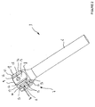
- FIG. 1 shows a device 1 for immobilizing a spinal implant 4 for locking in rotation and in translation of a connecting rod 2 at the level of each instrumented vertebra of a vertebral column.
- the immobilizing device 1 consists of a bone anchoring element 3 and a locking element 5 intended to cooperate with the anchoring element 3 for fixing in rotation and in translation of the connecting rod 2 .
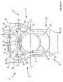
- FIG. 2 shows the bone anchoring element 3 comprising an anchoring part 6 and a receiving part 7.
- the anchoring part 6 can have either the shape of a hook or a fixed threaded profile or not of the receiving part 7 to be fixed on / or in the vertebral body of the vertebra to be instrumented.
- the receiving part 7 consists of a U-shaped head 8 open in its upper part 7 in order to cooperate with the connecting rod 2 and the locking element 5.
- the head 8 has two vertical walls 9, 10 arranged opposite each other and in parallel planes to define a central opening 11 in the shape of a U whose bottom 12 has a profile in cylinder portion.
- Each vertical wall 9, 10 consists of a central face 13 bordered laterally and on each side by elastic strips 14, 15 respectively separated from said central face by vertical slots 16, 17.
- each vertical wall 9, 10 is pierced with a hole 18 opening into the central opening 11 in the shape of a U.
- the elastic blades 14, 15 of the head 8 respectively comprise in their upper part a tooth 19, 20 whose outer profile 21, 22 is curved and inclined towards the outside of each vertical wall 9, 10.
- FIG. 3 shows the blocking element 5 of the immobilizing device 1 which has a substantially parallelepipedal external profile, each of the opposite faces 23, 24 of which; 25, 26, 27 and 28 are parallel in pairs.
- the lower face 24 of the locking element 5 comprises in a direction parallel to the axis XX 'of the connecting rod 2 a housing 29 having a profile portion of a cylinder.
- the upper face 23 of the locking element 5 comprises in its center a threaded bore 30 opening into the housing 29 and in which a clamping screw 31 cooperates.
- the first pair of lateral faces 25, 26 of the locking element 5 respectively comprises, above the housing 29, an impression 32 intended to cooperate with the teeth of an instrument, not shown, allowing the manipulation and the positioning of said element. locking on the bone anchoring element 3.
- the second pairs of lateral faces 27, 28 of the locking element 5 are each integral with two lugs 33, 34 arranged in the width of said locking element or in the extension of each lateral face 25, 26.
- the locking element 5 comprises four lugs 33, 34 extend towards the outside of the latter and in a direction perpendicular to the plane containing each lateral face 27, 28.
- Each lug 33, 34 respectively comprises in its upper part an inclined or chamfered portion 35, 36 directed towards the lateral faces 25, 26 so that the lower base of each inclined face 35, 36 is in the plane containing each of said lateral faces. 25, 26.
- Each lug 33, 34 has respectively in its lower part and on the opposite inclined faces 35, 36 a rounded profile 37, 38 for sliding said lugs on the teeth 19, 20 during assembly of the locking element 5 with the bone anchoring element 3.
- the distance d provided between two lugs 33, 34 of the same lateral face 27, 28 is smaller than that provided between two teeth 19, 20 of the same vertical wall 9, 10 of the head 8 of the anchoring element. bone 3.
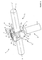
- FIGS. 4 and 5 illustrate the introduction and the retention of the locking element 5 on the head 8 of the anchoring element 3 in order to be able to lock in rotation and in translation the connecting rod 2 in each immobilization device 1 anchored to the vertebral body of a vertebra.
- the bone anchoring element 3 is fixed or hooked depending on its structure to the vertebral body of a vertebra to be instrumented.
- the connecting rod 2 is positioned inside the central opening 11 of the head 8 of the bone anchoring element 3.
- the locking element 5 is positioned above the head 8 of the bone anchoring element 3 so that the lugs 33, 34 of the same lateral face 27, 28 bear against the corresponding teeth 19, 20 of the same vertical wall 9, 10.
- a thrust force F is applied using an instrument, not shown, on the locking element 5 so that the lugs 33, 34 of each lateral face 27, 28 laterally deforms the elastic blades 14, 15 of each wall 9, 10 of the head 8 of the bone anchoring element 3.
- the elastic deformation of the blades 14, 15 is effected in the direction of the central face 13 of each vertical wall 9, 10 of the head 8 because of the difference in width provided between the lugs 33, 34 and the teeth 19, 20 ( Figure 4).
- each lug 33, 34 has a lower part with a rounded profile 37, 38 which slides on the curved outer profile 21, 22 of each tooth 19, 20 integral with the blades. 14, 15.
- the thrust force F must be sufficient for each lug 33, 34 to engage with the corresponding tooth 19, 20 of the elastic blades 14, 15.
- the retention of the lugs 33, 34 is obtained when each inclined section 35, 36 cooperates with the profile of the tooth 19, 20 corresponding ( Figure 5).
- the retention of the lugs 33, 34 is obtained by the elasticity of the blades 14, 15 which return to the rest position after the passage of the lugs 33, 34 on the teeth 19, 20 corresponding.
- the connecting rod 2 is then immobilized in rotation and in translation through the clamping screw 31 which is screwed inside the bore 30 of the locking element 5.
- the clamping screw 31 under the tightening force, comes to block the connecting rod 2 against the bottom 12 in cylinder portion of the central opening 11 of the head 8 of the anchoring element 3.
- the clamping force of the pressure screw 31 against the connecting rod 2 allows, by means of a vertical displacement directed in a direction opposite to that of said rod, to block the locking element 5 in the head 8 of the anchoring element 3.
- FIGS. 6 to 10 show a first variant of the spinal implant and more particularly the immobilization device 1 for locking in rotation and in translation of the connecting rod 2 at the level of each instrumented vertebra of a spinal column. .
- the immobilizing device 1 consists of a bone anchoring element 3 and a locking element 5 intended to cooperate with the anchoring element 3 for fixing in rotation and in translation of the connecting rod 2 .
- FIG. 7 shows the bone anchoring element 3 comprising an anchoring part 6 and a receiving part 7.
- the anchoring part 6 may have either the shape of a hook or a fixed threaded profile or not of the receiving part 7 to be fixed on / or in the vertebral body of the vertebra to be instrumented.
- the receiving part 7 consists of a U-shaped head 8, open in its upper part to be able to cooperate with the connecting rod 2 and the locking element 5.
- the head 8 comprises two vertical walls 9, 10 with a truncated profile, arranged opposite each other and in parallel planes in order to define a first central opening 11 in the shape of a U carried by the axis XX 'of the connecting rod 2 and whose bottom 12 has a profile in cylinder portion and a second opening 39 perpendicular to the axis XX 'and the first opening 11.
- the two perpendicular openings 11 and 39 define at each angle of the head 8 retaining means 14, 15 may deform elastically under a thrust F.
- Each truncated vertical wall 9, 10 consists of a central face 13 whose height is delimited by the second opening 39 passing through the head 8 of the receiving part 7.
- Each central face 13 is bordered laterally and on each side by elastic strips 14, 15 respectively separated from said central face by vertical slots 16, 17.
- each truncated vertical wall 9, 10 is pierced with a non-through hole 18 allowing an instrumentation to hang on to allow the insertion of the locking element 5 into the anchoring element 3 .
- the elastic blades 14, 15 of the head 8 respectively comprise in their upper part a tooth 19, 20 whose attachment profile 40, 41 is turned towards the inside of the second opening 39 and above the face. central 13 of each vertical wall 9, 10.
- Each tooth 19, 20 has above its attachment portion 40, 41 and towards the opening 39 an inclined outer profile 42, 43 extending towards the outside of each blade 14, 15 by a profile curved 44, 45.
- FIG. 8 shows the blocking element 5 of the immobilizing device 1 which has a substantially parallelepipedal external profile, each of the opposite faces 23, 24 of which; 25, 26, 27 and 28 are parallel in pairs.
- the lower face 24 of the locking element 5 comprises, in a direction parallel to the axis XX ', a housing 29 having a profile in a portion of a cylinder in order to receive the connecting rod 2 during assembly and fixing of the immobilizer 1.
- the upper face 23 of the locking element 5 comprises in its center a threaded bore 30 opening into the housing 29 and in which a clamping screw 31 cooperates.
- the locking element 5 comprises two lugs 33 and two lugs 34 which extend towards the outside of the latter.
- Each lug 33, 34 respectively comprises a hooking portion 48, 49 delimited by an arrangement of inclined and curved profiles for cooperation with the attachment portions 40, 41 of each tooth 19, 20 during the installation of the lug. blocking element 5 in the head 8 of the anchoring element 3.
- attachment portions 48, 49 of each lug 33, 34 are positioned at a distance and at a distance d1 from the lateral and opposite sides 25, 26 of the locking element 5.
- Each lug 33, 34 has respectively an inclined outer profile 37, 38 for sliding said lugs and the spacing of the elastic blades 14, 15 to the outside of the head 8 in order to achieve the assembly of the locking element 5 with the bone anchoring element 3.
- FIGS. 9 and 10 show the different steps for assembling the blocking element 5 in the head 8 of the anchoring element 3 in order to fix the connecting rod 2 in rotation and in translation. in each immobilization device 1 anchored in the vertebral body of a vertebra.
- the bone anchoring element 3 is fixed or hooked according to its structure to a vertebra to be instrumented.
- the connecting rod 2 is positioned inside the central opening 11 of the head 8 of the bone anchoring element 3 before the introduction of the locking element 5.
- the locking element 5 is positioned above the head 8 of the bone anchoring element 3 so that the lugs 33, 34 of the same lateral face 27, 28 bear against the corresponding teeth 19, 20 of the same vertical wall 9, 10.
- a thrust force F is made in a substantially vertical direction using an instrument, not shown, on the locking element 5 so that the lugs 33, 34 of each lateral face 27, 28 laterally deform the elastic blades. 14, 15 of each wall 9, 10 of the head 8 of the bone anchoring element 3.
- the elastic deformation of the blades 14, 15 is effected in the direction of the outside of the head 8, ie in a direction which moves away from the central face 13 of each vertical wall 9, 10 of the head 8 , due to the difference in the dimensions provided between the lugs 33, 34 and the teeth 19, 20 ( Figure 9).
- each lug 33, 34 has a lower inclined profile portion 37, 38 which slides on the outer profile of each tooth 19, 20 integral with the blades 14, 15.
- the thrust force F must be sufficient for each attachment portion 48, 49 of the lugs 33, 34 to snap into engagement with the attachment portion 40, 41 of each corresponding tooth 19, 20 of the elastic blades 14, 15.
- the retention of the locking element 5 is obtained by the elasticity of the blades 14, 15 which return to the rest position after the passage of the lugs 33, 34 on the teeth 19, 20 corresponding.
- the connecting rod 2 is slidably fitted in a cylindrical groove formed by the bottom 12 having a cylindrical portion profile of the head 8 of the bone anchoring element 3 and the housing 29 having a cylindrical portion profile of the the blocking element 5.
- the connecting rod 2 is then immobilized in rotation and in translation through the clamping screw 31 which is screwed inside the bore 30 of the locking element 5.
- the clamping screw 31 under the tightening force, comes to block the connecting rod 2 against the bottom 12 in cylinder portion of the central opening 11 of the head 8 of the anchoring element 3.
- the clamping force of the pressure screw 31 against the connecting rod 2 allows, by means of a vertical displacement directed in a direction opposite to that of said rod, to block the locking element 5 in the head 8 of the anchoring element 3.
- FIGS. 11 to 18 show a second variant of the spinal implant and more particularly the immobilization device 1 for locking in rotation and in translation of a connecting rod 2 at the level of each instrumented vertebra of a column spinal.
- the immobilizing device 1 consists of a bone anchoring element 3 and a blocking element 5 intended to cooperate with the anchoring element 3 for fixing in rotation and in translation of the connecting rod 2 .
- the bone anchoring element 3 comprising an anchoring portion 6 and a receiving portion 7.
- the anchoring portion 6 can have either the shape of a hook or a threaded profile secured to the receiving part or not 7 to come to fix on / or in the vertebra to instrument.
- the receiving part 7 consists of a U-shaped head 8 open in its upper part to be able to cooperate with the connecting rod 2 and the locking element 5.
- the head 8 has two vertical walls 9, 10 arranged facing each other and in parallel planes in order to define a first central U-shaped opening 11 carried by the axis XX 'of the connecting rod 2 and whose bottom 12 has a cylinder portion profile.
- Each vertical wall 9, 10 is separated from the bottom 12 of the central opening 11 by a vertical slot 50 giving a certain elasticity to each wall in a direction YY 'perpendicular to that XX' of the connecting rod 2.
- the elastic vertical walls 9, 10 respectively comprise at each end a hook-shaped profile 14, 15 arranged facing each other and on either side of the central opening 11.
- Each elastic vertical wall 9, 10 has on its inner face and between the latching blades 14, 15 a vertical housing 51 having a profile in cylinder portion.
- the vertical housing 51 has on each side a groove 54 for guiding the locking element 5 when it is placed inside the U-shaped head 8.
- Each elastic vertical wall 9, 10 is pierced between the attachment blades 14, 15 of a hole 18 opening inside the central opening 11 allowing an instrumentation to hang on to allow the introduction of the blocking element 5 in the anchoring element 3.
- the attachment blades 14, 15 of the head 8 respectively comprise in their upper part a tooth 19, 20 whose attachment profile 40, 41 is turned towards the interior of the central opening 11.
- Each tooth 19, 20 has above its attachment portion 40, 41 an inclined outer profile 42, 43 extending towards the outside of each blade 14, 15 by a curved profile 44, 45.
- FIG. 14 shows the blocking element 5 of the immobilizing device 1 which has a substantially parallelepipedal external profile, each of the opposite faces 23, 24 of which; 25, 26, 27 and 28 are parallel in pairs.
- the lower face 24 of the blocking element 5 comprises, in a direction parallel to the axis XX ', a housing 29 having a profile in a portion of a cylinder in order to receive the connecting rod 2 during assembly and fixing of the device. of immobilization 1.
- the upper face 23 of the locking element 5 comprises in its center a threaded bore 30 opening into the housing 29 and in which a clamping screw 31 cooperates.
- Each side face 27, 28 disposed in a plane parallel to the axis XX 'of the housing 29 and perpendicular to each of the lateral faces 25, 26 of the locking element 5, comprises two lugs 33, 34 in the shape of a tooth.
- the locking element 5 comprises two lugs 33 and two lugs 34 which extend towards the outside of the latter.
- Each lug 33, 34 respectively comprises a hooking portion 48, 49 delimited by a cylinder-section profile for cooperation with the attachment portions 40, 41 of each tooth 19, 20 during the installation of the locking element 5 in the head 8 of the anchoring element 3 (FIG. 15)
- Each lug 33, 34 has respectively an inclined outer profile 37, 38 allowing the sliding of said lugs and the elastic spacing of the walls 9, 10 and thus the fastening blades 14, 15 in the direction YY 'in order to achieve the assembly of the locking element 5 with the bone anchoring element 3.
- each opposite face 27, 28 has in its middle and between the lugs 33, 34 a vertical housing 52 laterally bordered by ribs 53 for guiding the locking element 5 when it is inserted into the head 8 of the anchoring element 3.
- hooking portions 48, 49 are closed opposite the lateral faces 25, 26 via the corresponding vertical rib 53 and arranged between each lug 33, 34.
- Each vertical rib 53 may have an external profile of any shape, provided that its profile is complementary to that of the groove 54 formed in the thickness of the inner face of each vertical wall 9, 10 of the head 8 of the element d anchoring 3.
- the vertical housings 51 and 52 have a profile in complementary cylinder portion to allow the introduction of an instrument to ensure the removal of the locking element 5 of the head 8 of the anchoring element 3.
- FIGS. 15 to 18 show the various steps for assembling the blocking element 5 in the head 8 of the anchoring element 3 in order to fix in rotation and in translation the connecting rod 2 in each immobilization device 1 anchored in the vertebral body of a vertebra.
- the connecting rod 2 is positioned inside the central opening 11 of the head 8 of the bone anchoring element 3 before the introduction of the locking element 5.
- the locking element 5 is positioned above the head 8 of the bone anchoring element 3 so that the lugs 33, 34 of the same lateral face 27, 28 bear against the corresponding teeth 19, 20 of the same vertical wall 9, 10.
- a thrust force F is made in a substantially vertical direction by means of an instrument, not shown, on the locking element 5 so that the lugs 33, 34 of each lateral face 27, 28 deform laterally the vertical walls 9, 10 and thus the elastic latching blades 14, 15.
- the elastic deformation of the vertical walls 9, 10 is effected towards the outside of the head 8 because of the difference in dimensions provided between the lugs 33, 34 and the teeth 19, 20.
- each lug 33, 34 has a lower part with an inclined profile 37, 38 which slides on the external profile of each tooth 19, 20 of the attachment blades 14, 15 of each elastic wall 9, 10.
- the thrust force F must be sufficient for each latching portion 48, 49 of the lugs 33, 34 to engage with the latching portion 40, 41 of each tooth 19, 20 corresponding.
- the retention of the locking element 5 is obtained by the elasticity of the vertical walls 9, 10 and thus of the attachment blades 14, 15 which return to the rest position after the passage of the lugs 33, 34 on the teeth 19, 20 corresponding.
- the connecting rod 2 is slidably fitted in a cylindrical groove formed by the bottom 12 having a cylindrical portion profile of the head 8 of the bone anchoring element 3 and the housing 29 having a cylindrical portion profile of the the blocking element 5.
- the connecting rod 2 is then immobilized in rotation and in translation through the clamping screw 31 which is screwed inside the bore 30 of the locking element 5.
- the clamping screw 31 under the tightening force, comes to block the connecting rod 2 against the bottom 12 in cylinder portion of the central opening 11 of the head 8 of the anchoring element 3.
- the clamping force of the pressure screw 31 against the connecting rod 2 allows, by means of a vertical displacement directed in a direction opposite to that of said rod, to block the locking element 5 in the head 8 of the anchoring element 3.
- the removal of the blocking element 5 is obtained by means of an instrument which is introduced into the vertical housings 51 and 52 so as to spread the vertical walls 9, 10 towards the outside of the head 8 of the the anchoring element 3.
Landscapes
- Health & Medical Sciences (AREA)
- Orthopedic Medicine & Surgery (AREA)
- Life Sciences & Earth Sciences (AREA)
- Surgery (AREA)
- Neurology (AREA)
- Heart & Thoracic Surgery (AREA)
- Engineering & Computer Science (AREA)
- Biomedical Technology (AREA)
- Nuclear Medicine, Radiotherapy & Molecular Imaging (AREA)
- Medical Informatics (AREA)
- Molecular Biology (AREA)
- Animal Behavior & Ethology (AREA)
- General Health & Medical Sciences (AREA)
- Public Health (AREA)
- Veterinary Medicine (AREA)
- Surgical Instruments (AREA)
- Prostheses (AREA)
Abstract
Description
La présente invention est relative à un dispositif d'immobilisation d'une tige de liaison dans un élément d'ancrage osseux d'un implant rachidien.The present invention relates to a device for immobilizing a connecting rod in a bone anchoring element of a spinal implant.
On connaît différents types de dispositif d'immobilisation qui, du fait de leur structure particulière, permettent le blocage en rotation et en translation de la tige de liaison dans un élément d'ancrage osseux d'un implant rachidien.Various types of immobilization device are known which, because of their particular structure, allow locking in rotation and in translation of the connecting rod in a bone anchoring element of a spinal implant.
Le document
Le dispositif d'immobilisation suivant la présente invention a pour objet d'améliorer la retenue de l'élément de blocage sur l'élément d'ancrage osseux, tout en préservant des fixations indépendantes pour la retenue d'une part de la tige de liaison et d'autre de l'élément de blocage.The purpose of the immobilization device according to the present invention is to improve the retention of the locking element on the bone anchoring element, while preserving independent fastenings for retaining, on the one hand, the connecting rod and other of the blocking element.
Le dispositif d'immobilisation suivant la présente invention comporte un élément d'ancrage osseux comprenant des moyens de retenue susceptibles de se déformer élastiquement sous un effort de poussée F et un élément de blocage comprenant d'une part des ergots qui coopèrent avec les moyens de retenue pour permettre la fixation de l'élément de blocage sur l'élément d'ancrage osseux et d'autre part, une vis de serrage permettant l'immobilisation en rotation et en translation de la tige de liaison entre l'élément d'ancrage osseux et l'élément de blocage.The immobilizing device according to the present invention comprises a bone anchoring element comprising retaining means able to deform elastically under a thrust force F and a locking element comprising on the one hand lugs which cooperate with the retained to allow attachment of the locking element on the bone anchoring element and secondly, a clamping screw for immobilization in rotation and in translation of the connecting rod between the anchoring element bone and the blocking element.
Le dispositif d'immobilisation suivant la présente invention comprend :
- ❖ un élément d'ancrage osseux pourvu d'une tête comportant deux parois verticales délimitant une ouverture centrale en forme de U dont le fond présente un profil en portion de cylindre, chaque paroi verticale étant constituée d'une face centrale bordée latéralement et de chaque côté par des lames élastiques séparées respectivement de ladite face centrale par des fentes verticales, lesdites lames élastiques comportant respectivement dans leur partie supérieure une dent d'encliquetage,
- ❖ et un élément de blocage comportant un logement à profil en portion de cylindre, un alésage fileté débouchant à l'intérieur du logement, une vis de serrage coopérant avec l'alésage fileté et des ergots qui coopèrent respectivement avec une dent solidaire de lames élastiques.
- ❖ a bone anchoring element provided with a head comprising two vertical walls delimiting a central U-shaped opening whose bottom has a cylindrical portion profile, each vertical wall consisting of a laterally lined central face and each side by elastic strips respectively separated from said central face by vertical slots, said elastic blades respectively having in their upper part a ratchet tooth,
- And a blocking element comprising a housing having a cylinder-section profile, a threaded bore opening into the housing, a clamping screw cooperating with the threaded bore and lugs which cooperate respectively with a tooth secured to resilient blades. .
Le dispositif d'immobilisation suivant la présente invention comporte un élément d'ancrage osseux dont la face centrale de chaque paroi verticale est percée d'un trou débouchant à l'intérieur de l'ouverture centrale en forme de U.The immobilizing device according to the present invention comprises a bone anchoring element whose central face of each vertical wall is pierced with a hole opening into the central opening U-shaped.
Le dispositif d'immobilisation suivant la présente invention comporte un élément d'ancrage osseux dont les lames élastiques de la tête comportent respectivement dans leur partie supérieure une dent dont le profil externe est bombé et incliné.The immobilizing device according to the present invention comprises a bone anchoring element whose elastic blades of the head respectively comprise in their upper part a tooth whose external profile is curved and inclined.
Le dispositif d'immobilisation suivant la présente invention comporte un élément de blocage dont la face inférieure comprend, suivant une direction parallèle à l'axe XX' de la tige de liaison, un logement présentant un profil en portion de cylindre.The immobilizer according to the present invention comprises a locking element whose lower face comprises, in a direction parallel to the axis XX 'of the connecting rod, a housing having a profile in cylinder portion.
Le dispositif d'immobilisation suivant la présente invention comporte un élément de blocage dont la face supérieure, opposée à celle inférieure, comprend en son milieu un alésage fileté débouchant à l'intérieur du logement et dans lequel coopère une vis de serrage.The immobilizer according to the present invention comprises a locking element whose upper face, opposite to the lower one, comprises in its middle a threaded bore opening into the housing and in which a clamping screw cooperates.
Le dispositif d'immobilisation suivant la présente invention comporte un élément de blocage qui présente une première paire de faces latérales opposées comportant respectivement au dessus du logement une empreinte destinée à coopérer un instrument pour la manipulation et la mise en place dudit élément de blocage sur l'élément d'ancrage osseux.The immobilizing device according to the present invention comprises a locking element which has a first pair of opposite lateral faces respectively comprising, above the housing, a recess intended to cooperate with an instrument for the manipulation and positioning of said locking element on the bone anchoring element.
Le dispositif d'immobilisation suivant la présente invention comporte un élément de blocage qui présente une seconde paire de faces latérales opposées qui sont solidaires chacune de deux ergots disposés dans la largeur dudit élément de blocage et positionnés dans le prolongement de la première paire de faces latérales.The immobilizing device according to the present invention comprises a locking element which has a second pair of opposite lateral faces which are each integral with two lugs arranged in the width of said locking element and positioned in the extension of the first pair of lateral faces. .
Le dispositif d'immobilisation suivant la présente invention comporte un élément de blocage dont chaque ergot comprend respectivement dans sa partie supérieure un pan incliné ou chanfrein dont la base inférieure est positionnée dans le plan contenant chacune desdites premières paires de faces latérales.The immobilizing device according to the present invention comprises a locking element each lug comprises respectively in its upper part an inclined pan or chamfer whose lower base is positioned in the plane containing each of said first pairs of side faces.
Le dispositif d'immobilisation suivant la présente invention comporte un élément de blocage dont chaque ergot comprend respectivement dans sa partie inférieure et à l'opposé des pans inclinés, un profil arrondi.The immobilizer according to the present invention comprises a locking element, each lug comprises respectively in its lower part and opposite inclined faces, a rounded profile.
Le dispositif d'immobilisation suivant la présente invention comporte un élément de blocage dont la distance d séparant deux ergots est inférieure à celle prévue entre deux dents d'une même paroi verticale de l'élément d'ancrage osseux.The immobilizing device according to the present invention comprises a locking element whose distance d separating two lugs is less than that provided between two teeth of the same vertical wall of the bone anchoring element.
Le dispositif d'immobilisation suivant la présente invention comporte des lames élastiques qui se déforment, sous une force de poussée F appliquée sur l'élément de blocage, latéralement en direction de la face centrale de chaque paroi de l'élément d'ancrage osseux.
Le dispositif d'immobilisation suivant la présente invention comprend :
- un élément d'ancrage osseux pourvu d'une tête comportant deux parois verticales tronquées délimitant une ouverture centrale en forme de U dont le fond présente un profil en portion de cylindre, chaque paroi verticale étant constituée d'une face centrale bordée latéralement et de chaque côté par des lames élastiques séparées respectivement de ladite face centrale par des fentes verticales, lesdites lames élastiques comportant respectivement dans leur partie supérieure une dent d'encliquetage,
- et un élément de blocage comportant un logement à profil en portion de cylindre, un alésage fileté débouchant à l'intérieur du logement, une vis de serrage coopérant avec l'alésage fileté et des ergots qui coopèrent respectivement avec une dent solidaire des lames élastiques.
The immobilizer according to the present invention comprises:
- a bone anchoring element provided with a head having two truncated vertical walls delimiting a central U-shaped opening whose bottom has a cylinder-section profile, each vertical wall consisting of a laterally-lined central face and each side by respective elastic strips separated from said central face by vertical slots, said resilient blades respectively having in their upper part a detent tooth,
- and a locking element comprising a housing with a cylinder-section profile, a threaded bore opening into the housing, a clamping screw cooperating with the threaded bore and lugs which cooperate respectively with a tooth integral with the resilient blades.
Le dispositif d'immobilisation suivant la présente invention comporte une tête comprenant deux parois verticales à profil tronqué disposées l'une en face de l'autre et dans des plans parallèles afin de délimiter une première ouverture centrale en forme de U portée par l'axe XX' de la tige de liaison et dont le fond présente un profil en portion de cylindre et une seconde ouverture perpendiculaire à l'axe XX' et à la première ouverture.The immobilizing device according to the present invention comprises a head comprising two vertical walls with a truncated profile disposed opposite each other and in parallel planes in order to define a first central U-shaped opening carried by the axis. XX 'of the connecting rod and whose bottom has a profile in a cylinder portion and a second opening perpendicular to the axis XX' and the first opening.
Le dispositif d'immobilisation suivant la présente invention comporte une tête comprenant deux ouvertures perpendiculaires qui permettent de délimiter à chaque angle de la tête des lames élastiques susceptibles de se déformer élastiquement sous un effort de poussée F.The immobilizing device according to the present invention comprises a head comprising two perpendicular openings which make it possible to define at each angle of the head resilient blades that can deform elastically under a thrust force F.
Le dispositif d'immobilisation suivant la présente invention comporte une tête pourvue de lames élastiques comprenant respectivement dans leur partie supérieure une dent dont le profil d'accrochage est tourné en direction de l'intérieur de la seconde ouverture et au-dessus de la face centrale de chaque paroi verticale.The immobilizing device according to the present invention comprises a head provided with elastic blades respectively comprising in their upper part a tooth whose hooking profile is turned towards the inside of the second opening and above the central face. of each vertical wall.
Le dispositif d'immobilisation suivant la présente invention comporte une tête dont chaque dent comprend, au-dessus de sa partie d'accrochage et en direction de l'ouverture, un profil externe incliné se prolongeant en direction de l'extérieur par un profil bombé.The immobilizing device according to the present invention comprises a head of which each tooth comprises, above its attachment portion and in the direction of the opening, an inclined external profile extending towards the outside by a curved profile. .
Le dispositif d'immobilisation suivant la présente invention comporte un élément de blocage comprenant une face inférieure comprenant suivant une direction parallèle à l'axe XX' un logement présentant un profil en portion de cylindre afin de coopérer avec la tige de liaison, une face supérieure comprenant en son milieu un alésage fileté débouchant à l'intérieur du logement et dans lequel coopère une vis de serrage, et des faces latérales parallèles deux à deux et dont deux au moins sont solidaires respectivement de deux ergots en forme de dent.The immobilizing device according to the present invention comprises a locking element comprising a lower face comprising in a direction parallel to the axis XX 'a housing having a profile in a portion of a cylinder in order to cooperate with the connecting rod, an upper surface comprising in its middle a threaded bore opening into the housing and in which a clamping screw cooperates, and side faces parallel in pairs and at least two of which are secured respectively to two tooth-shaped lugs.
Le dispositif d'immobilisation suivant la présente invention comporte un élément de blocage dont chaque ergot comprend une partie d'accrochage positionnée en retrait et à une certaine distance d1 des faces latérales et opposées de l'élément de blocage.The immobilizer according to the present invention comprises a locking element, each lug comprises a latching portion positioned at a distance and at a distance d1 from the lateral and opposite faces of the locking element.
Le dispositif d'immobilisation suivant la présente invention comprend :
- un élément d'ancrage osseux pourvu d'une tête comportant deux parois verticales délimitant une ouverture centrale en forme de U dont le fond présente un profil en portion de cylindre, chaque paroi verticale étant séparée du fond de l'ouverture centrale par une fente verticale donnant une certaine élasticité à chaque paroi selon une direction YY', lesdites parois verticales comprenant respectivement à chaque extrémité un profil en forme de lame d'accrochage élastique disposée l'une en face de l'autre et de part et d'autre de l'ouverture centrale, lesdites lames élastiques comportant respectivement dans leur partie supérieure une dent d'encliquetage,
- et un élément de blocage comportant un logement à profil en portion de cylindre, un alésage fileté débouchant à l'intérieur du logement, une vis de serrage coopérant avec l'alésage fileté et des ergots qui coopèrent respectivement avec une dent solidaire des lames élastiques.
Le dispositif d'immobilisation suivant la présente invention comporte une tête dont chaque paroi verticale comprend sur sa face interne et entre les lames d'accrochage un logement vertical.
- a bone anchoring element provided with a head having two vertical walls delimiting a central U-shaped opening whose bottom has a cylindrical portion profile, each vertical wall being separated from the bottom of the central opening by a vertical slot giving a certain elasticity to each wall in a direction YY ', said vertical walls respectively comprising at each end a profile shaped resilient gripping blade disposed opposite one another and on either side of the central opening, said elastic blades respectively having in their upper part a tooth d snap,
- and a locking element comprising a housing with a cylinder-section profile, a threaded bore opening into the housing, a clamping screw cooperating with the threaded bore and lugs which cooperate respectively with a tooth integral with the resilient blades.
The immobilizing device according to the present invention comprises a head of which each vertical wall comprises on its inner face and between the attachment blades a vertical housing.
Le dispositif d'immobilisation suivant la présente invention comporte une tête dont les lames élastiques comprennent respectivement dans leur partie supérieure une dent dont le profil d'accrochage est tourné en direction de l'intérieur de l'ouverture centrale.The immobilizing device according to the present invention comprises a head whose elastic blades respectively comprise in their upper part a tooth whose hooking profile is turned towards the interior of the central opening.
Le dispositif d'immobilisation suivant la présente invention comporte une tête dont chaque dent comprend au-dessus de sa partie d'accrochage et en direction de l'ouverture un profil externe incliné se prolongeant en direction de l'extérieur par un profil bombé.The immobilizing device according to the present invention comprises a head of which each tooth comprises above its attachment portion and towards the opening an inclined outer profile extending towards the outside by a curved profile.
Le dispositif d'immobilisation suivant la présente invention comporte un élément de blocage comprenant une face inférieure comprenant, suivant une direction parallèle à l'axe XX', un logement présentant un profil en portion de cylindre afin de coopérer avec la tige de liaison, une face supérieure comprenant en son milieu un alésage fileté débouchant à l'intérieur du logement et dans lequel coopère une vis de serrage et des faces latérales parallèles deux à deux et dont deux au moins sont solidaires respectivement de deux ergots en forme de dent.The immobilizing device according to the present invention comprises a locking element comprising a lower face comprising, in a direction parallel to the axis XX ', a housing having a profile in a portion of a cylinder in order to cooperate with the connecting rod, a upper face comprising in its center a threaded bore opening into the housing and in which cooperates a clamping screw and parallel side faces in pairs and at least two of which are integral respectively with two tooth-shaped lugs.
Le dispositif d'immobilisation suivant la présente invention comporte un élément de blocage dont chaque face latérale disposée dans un plan parallèle à l'axe XX' du logement comporte deux ergots en forme de dent séparés par une nervure verticale présentant un logement central vertical.The immobilizer according to the present invention comprises a locking element, each side face disposed in a plane parallel to the axis XX 'of the housing comprises two tooth-shaped lugs separated by a vertical rib having a vertical central housing.
Le dispositif d'immobilisation suivant la présente invention comporte un élément de blocage dont les parties d'accrochage des ergots sont fermées à l'opposé des faces latérales par l'intermédiaire de la nervure verticale correspondante.The immobilizing device according to the present invention comprises a locking element whose attachment portions of the lugs are closed opposite the side faces through the corresponding vertical rib.
La description qui va suivre en regard des dessins annexés, donnés à titre d'exemples non limitatifs, permettra de mieux comprendre l'invention, les caractéristiques qu'elle présente et les avantages qu'elle est susceptible de procurer :
- Figure 1 est une vue en perspective éclatée illustrant le dispositif d'immobilisation suivant la présente invention.
- Figure 2 est une vue en perspective montrant l'élément d'ancrage osseux du dispositif d'immobilisation suivant la présente invention.
- Figure 3 est une vue en perspective représentant l'élément de blocage en translation et en rotation de la tige de liaison à l'intérieur de l'élément d'ancrage osseux du dispositif d'immobilisation suivant la présente invention.
- Figure 4 est une vue en perspective illustrant la déformation élastique de l'élément d'ancrage osseux lors du montage de l'élément de blocage du dispositif d'immobilisation suivant la présente invention.
- Figure 5 est une vue en perspective montrant le dispositif d'immobilisation en position assemblée pour le blocage en rotation et en translation de la tige de liaison de l'implant rachidien.
- Figure 6 est une vue en perspective éclatée illustrant une première variante du dispositif d'immobilisation suivant la présente invention.
- Figure 7 est une vue en perspective montrant l'élément d'ancrage osseux de la première variante du dispositif d'immobilisation suivant la présente invention.
- Figure 8 est une vue en perspective représentant l'élément de blocage en translation et en rotation de la tige de liaison à l'intérieur de l'élément d'ancrage osseux de la première variante du dispositif d'immobilisation suivant la présente invention.
- Figure 9 est une vue en perspective illustrant la déformation élastique de l'élément d'ancrage osseux lors du montage de l'élément de blocage de la première variante du dispositif d'immobilisation suivant la présente invention.
- Figure 10 est une vue en perspective montrant la première variante du dispositif d'immobilisation en position assemblée pour le blocage en rotation et en translation de la tige de liaison de l'implant rachidien.
- Figure 11 est une vue en perspective éclatée illustrant une seconde variante du dispositif d'immobilisation suivant la présente invention.
- Figure 12 et 13 sont des vues en perspective montrant l'élément d'ancrage osseux de la seconde variante du dispositif d'immobilisation suivant la présente invention.
- Figure 14 est une vue en perspective représentant l'élément de blocage en translation et en rotation de la tige de liaison à l'intérieur de l'élément d'ancrage osseux de la seconde variante du dispositif d'immobilisation suivant la présente invention.
- Figures 15 et 16 sont des vues illustrant la déformation élastique de l'élément d'ancrage osseux lors du montage de l'élément de blocage de la seconde variante du dispositif d'immobilisation suivant la présente invention.
- Figure 17 et 18 sont des vues en perspective montrant une seconde variante du dispositif d'immobilisation en position assemblée pour le blocage en rotation et en translation de la tige de liaison de l'implant rachidien.
- Figure 1 is an exploded perspective view illustrating the immobilizer of the present invention.
- Figure 2 is a perspective view showing the bone anchoring element of the immobilizer according to the present invention.
- Figure 3 is a perspective view showing the locking element in translation and rotation of the connecting rod inside the bone anchoring element of the immobilizer according to the present invention.
- Figure 4 is a perspective view illustrating the elastic deformation of the bone anchoring element during mounting of the locking element of the immobilizer according to the present invention.
- Figure 5 is a perspective view showing the immobilization device in the assembled position for locking in rotation and in translation of the connecting rod of the spinal implant.
- Figure 6 is an exploded perspective view illustrating a first variant of the immobilizer according to the present invention.
- Figure 7 is a perspective view showing the bone anchoring element of the first variant of the immobilizer according to the present invention.
- Figure 8 is a perspective view showing the locking element in translation and in rotation of the connecting rod inside the bone anchoring element of the first variant of the immobilizer according to the present invention.
- Figure 9 is a perspective view illustrating the elastic deformation of the bone anchoring element during assembly of the locking element of the first variant of the immobilizer according to the present invention.
- Figure 10 is a perspective view showing the first variant of the immobilizer in the assembled position for locking in rotation and in translation of the connecting rod of the spinal implant.
- Figure 11 is an exploded perspective view illustrating a second variant of the immobilizer according to the present invention.
- Figures 12 and 13 are perspective views showing the bone anchor element of the second variant of the immobilizer according to the present invention.
- Figure 14 is a perspective view showing the locking element in translation and rotation of the connecting rod inside the bone anchoring element of the second variant of the immobilizer according to the present invention.
- Figures 15 and 16 are views illustrating the elastic deformation of the bone anchoring element during mounting of the blocking element of the second variant of the immobilizer according to the present invention.
- Figure 17 and 18 are perspective views showing a second variant of the immobilization device in the assembled position for locking in rotation and in translation of the connecting rod of the spinal implant.
On a montré en figure 1 un dispositif d'immobilisation 1 d'un implant rachidien 4 pour le blocage en rotation et en translation d'une tige de liaison 2 au niveau de chaque vertèbre instrumentée d'une colonne vertébrale.FIG. 1 shows a device 1 for immobilizing a
Le dispositif d'immobilisation 1 est constitué d'un élément d'ancrage osseux 3 et d'un élément de blocage 5 destiné à coopérer avec l'élément d'ancrage 3 pour la fixation en rotation et en translation de la tige de liaison 2.The immobilizing device 1 consists of a
On a représenté en figure 2 l'élément d'ancrage osseux 3 comprenant une partie d'ancrage 6 et une partie de réception 7. La partie d'ancrage 6 peut présenter soit la forme d'un crochet, soit un profil fileté solidaire ou non de la partie de réception 7 pour venir se fixer sur/ou dans le corps vertébral de la vertèbre à instrumenter.FIG. 2 shows the
La partie de réception 7 est constituée d'une tête 8 en forme de U ouverte dans sa partie supérieure 7 pour pouvoir coopérer avec la tige de liaison 2 et l'élément de blocage 5.The receiving
La tête 8 comporte deux parois verticales 9, 10 disposées l'une en face de l'autre et dans des plans parallèles afin de délimiter une ouverture centrale 11 en forme de U dont le fond 12 présente un profil en portion de cylindre.The
Chaque paroi verticale 9, 10 est constituée d'une face centrale 13 bordée latéralement et de chaque côté par des lames élastiques 14, 15 séparées respectivement de ladite face centrale par des fentes verticales 16, 17.Each
La face centrale 13 de chaque paroi verticale 9, 10 est percée d'un trou 18 débouchant à l'intérieur de l'ouverture centrale 11 en forme de U.The
Les lames élastiques 14, 15 de la tête 8 comportent respectivement dans leur partie supérieure une dent 19, 20 dont le profil externe 21, 22 est bombé et incliné en direction de l'extérieur de chaque paroi verticale 9, 10.The
On a montré en figure 3 l'élément de blocage 5 du dispositif d'immobilisation 1 qui présente un profil externe sensiblement parallélépipédique dont chacune des faces opposées 23, 24; 25, 26, 27 et 28 sont parallèles deux à deux.FIG. 3 shows the blocking element 5 of the immobilizing device 1 which has a substantially parallelepipedal external profile, each of the opposite faces 23, 24 of which; 25, 26, 27 and 28 are parallel in pairs.
Ainsi la face inférieure 24 de l'élément de blocage 5 comporte suivant une direction parallèle à l'axe XX' de la tige de liaison 2 un logement 29 présentant un profil en portion de cylindre.Thus the
La face supérieure 23 de l'élément de blocage 5 comporte en son milieu un alésage fileté 30 débouchant à l'intérieur du logement 29 et dans lequel coopère une vis de serrage 31.The
La première paire de faces latérales 25, 26 de l'élément de blocage 5 comporte respectivement au dessus du logement 29 une empreinte 32 destinée à coopérer avec les dents d'un instrument, non représentées, permettant la manipulation et la mise en place dudit élément de blocage sur l'élément d'ancrage osseux 3.The first pair of lateral faces 25, 26 of the locking element 5 respectively comprises, above the
Les secondes paires de faces latérales 27, 28 de l'élément de blocage 5 sont solidaires chacune de deux ergots 33, 34 disposés dans la largeur dudit élément de blocage soit dans le prolongement de chaque face latérale 25, 26.The second pairs of lateral faces 27, 28 of the locking element 5 are each integral with two
Ainsi, l'élément de blocage 5 comporte quatre ergots 33, 34 s'étendent en direction de l'extérieur de ce dernier et suivant une direction perpendiculaire au plan contenant chaque face latérale 27, 28.Thus, the locking element 5 comprises four
Chaque ergot 33, 34 comporte respectivement dans sa partie supérieure un pan incliné ou chanfrein 35, 36 dirigé en direction des faces latérales 25, 26 de manière que la base inférieure de chaque pan incliné 35, 36 soit dans le plan contenant chacune desdites faces latérales 25, 26.Each
Chaque ergot 33, 34 comporte respectivement dans sa partie inférieure et à l'opposé des pans inclinés 35, 36 un profil arrondi 37, 38 permettant le glissement desdits ergots sur les dents 19, 20 lors de l'assemblage de l'élément de blocage 5 avec l'élément d'ancrage osseux 3.Each
La distance d prévue entre deux ergots 33, 34 d'une même face latérale 27, 28 est inférieure à celle prévue entre deux dents 19, 20 d'une même paroi verticale 9, 10 de la tête 8 de l'élément d'ancrage osseux 3.The distance d provided between two
On a illustré en figures 4 et 5 la mise en place et la retenue de l'élément de blocage 5 sur la tête 8 de l'élément d'ancrage 3 afin de pouvoir bloquer en rotation et en translation la tige de liaison 2 dans chaque dispositif d'immobilisation 1 ancré de le corps vertébral d'une vertèbre.FIGS. 4 and 5 illustrate the introduction and the retention of the locking element 5 on the
L'élément d'ancrage osseux 3 est fixé ou accroché en fonction de sa structure au corps vertébral d'une vertèbre à instrumenter.The
La tige de liaison 2 est positionnée à l'intérieur de l'ouverture centrale 11 de la tête 8 de l'élément d'ancrage osseux 3.The connecting
L'élément de blocage 5 est positionné au dessus de la tête 8 de l'élément d'ancrage osseux 3 de manière que les ergots 33, 34 d'une même face latérale 27, 28 viennent en appui contre les dents correspondantes 19, 20 d'une même paroi verticale 9, 10.The locking element 5 is positioned above the
Une force de poussée F est appliquée à l'aide d'un instrument, non représenté, sur l'élément de blocage 5 afin que les ergots 33, 34 de chaque face latérale 27, 28 déforme latéralement les lames élastiques 14, 15 de chaque paroi 9, 10 de la tête 8 de l'élément d'ancrage osseux 3.A thrust force F is applied using an instrument, not shown, on the locking element 5 so that the
La déformation élastique des lames 14, 15 s'effectue en direction de la face centrale 13 de chaque paroi verticale 9, 10 de la tête 8 du fait de la différence de largeur prévue entre les ergots 33, 34 et les dents 19, 20 (figure 4).The elastic deformation of the
L'introduction de l'élément de blocage 5 est facilitée par le fait que chaque ergot 33, 34 présente une partie inférieure à profil arrondi 37, 38 qui glisse sur le profil externe bombé 21, 22 de chaque dent 19, 20 solidaire des lames 14, 15.The introduction of the locking element 5 is facilitated by the fact that each
La force de poussée F doit être suffisante pour que chaque ergot 33, 34 vienne s'encliqueter avec la dent 19, 20 correspondante des lames élastiques 14, 15. La retenue des ergots 33, 34 est obtenue lorsque chaque pan incliné 35, 36 coopère avec le profil de la dent 19, 20 correspondante (figure 5).The thrust force F must be sufficient for each
Egalement, la retenue des ergots 33, 34 est obtenue par l'élasticité des lames 14, 15 qui reviennent en position de repos après le passage des ergots 33, 34 sur les dents 19, 20 correspondantes.Also, the retention of the
La tige de liaison 2 est ensuite immobilisée en rotation et en translation par l'intermédiaire de la vis de serrage 31 qui est vissée à l'intérieur de l'alésage 30 de l'élément de blocage 5. La vis de serrage 31, sous l'effort de vissage, vient bloquer la tige de liaison 2 contre le fond 12 en portion de cylindre de l'ouverture centrale 11 de la tête 8 de l'élément d'ancrage 3.The connecting
Egalement, l'effort de serrage de la vis de pression 31 contre la tige de liaison 2 permet, par l'intermédiaire d'un déplacement vertical dirigé suivant une direction opposée à celle de ladite tige, de bloquer l'élément de blocage 5 dans la tête 8 de l'élément d'ancrage 3.Also, the clamping force of the
On a montré en figures 6 à 10 une première variante de l'implant rachidien et plus particulièrement du dispositif d'immobilisation 1 pour le blocage en rotation et en translation de la tige de liaison 2 au niveau de chaque vertèbre instrumentée d'une colonne vertébrale.FIGS. 6 to 10 show a first variant of the spinal implant and more particularly the immobilization device 1 for locking in rotation and in translation of the connecting
Par souci de clarté, les éléments identiques à ceux décrits précédemment présentent la même référence afin d'éviter toute confusion.For the sake of clarity, the elements identical to those described above have the same reference to avoid confusion.
Le dispositif d'immobilisation 1 est constitué d'un élément d'ancrage osseux 3 et d'un élément de blocage 5 destiné à coopérer avec l'élément d'ancrage 3 pour la fixation en rotation et en translation de la tige de liaison 2.The immobilizing device 1 consists of a
On a représenté en figure 7 l'élément d'ancrage osseux 3 comprenant une partie d'ancrage 6 et une partie de réception 7. La partie d'ancrage 6 peut présenter soit la forme d'un crochet, soit un profil fileté solidaire ou non de la partie de réception 7 pour venir se fixer sur/ou dans le corps vertébral de la vertèbre à instrumenter.FIG. 7 shows the
La partie de réception 7 est constituée d'une tête 8 en forme de U, ouverte dans sa partie supérieure pour pouvoir coopérer avec la tige de liaison 2 et l'élément de blocage 5.The receiving
La tête 8 comporte deux parois verticales 9, 10 à profil tronqué, disposées l'une en face de l'autre et dans des plans parallèles afin de délimiter une première ouverture centrale 11 en forme de U portée par l'axe XX' de la tige de liaison 2 et dont le fond 12 présente un profil en portion de cylindre et une seconde ouverture 39 perpendiculaire à l'axe XX' et à la première ouverture 11.The
Les deux ouvertures perpendiculaires 11 et 39 permettent de délimiter à chaque angle de la tête 8 des moyens de retenue 14, 15 susceptibles de se déformer élastiquement sous un effort de poussée F.The two
Chaque paroi verticale tronquée 9, 10 est constituée d'une face centrale 13 dont la hauteur est délimitée par la seconde ouverture 39 traversant la tête 8 de la partie de réception 7.Each truncated
Chaque face centrale 13 est bordée latéralement et de chaque côté par des lames élastiques 14, 15 séparées respectivement de ladite face centrale par des fentes verticales 16, 17.Each
La face centrale 13 de chaque paroi verticale tronquée 9, 10 est percée d'un trou 18 non débouchant permettant à une instrumentation de venir s'accrocher pour permettre l'introduction de l'élément de blocage 5 dans l'élément d'ancrage 3.The
Les lames élastiques 14, 15 de la tête 8 comportent respectivement dans leur partie supérieure une dent 19, 20 dont le profil d'accrochage 40, 41 est tourné en direction de l'intérieur de la seconde ouverture 39 et au-dessus de la face centrale 13 de chaque paroi verticale 9, 10.The
Chaque dent 19, 20 comporte au-dessus de sa partie d'accrochage 40, 41 et en direction de l'ouverture 39 un profil externe incliné 42, 43 se prolongeant en direction de l'extérieur de chaque lame 14, 15 par un profil bombé 44, 45.Each
On a montré en figure 8 l'élément de blocage 5 du dispositif d'immobilisation 1 qui présente un profil externe sensiblement parallélépipédique dont chacune des faces opposées 23, 24; 25, 26, 27 et 28 sont parallèles deux à deux.FIG. 8 shows the blocking element 5 of the immobilizing device 1 which has a substantially parallelepipedal external profile, each of the opposite faces 23, 24 of which; 25, 26, 27 and 28 are parallel in pairs.
Ainsi, la face inférieure 24 de l'élément de blocage 5 comporte suivant une direction parallèle à l'axe XX' un logement 29 présentant un profil en portion de cylindre afin de recevoir la tige de liaison 2 lors du montage et de la fixation du dispositif d'immobilisation 1.Thus, the
La face supérieure 23 de l'élément de blocage 5 comporte en son milieu un alésage fileté 30 débouchant à l'intérieur du logement 29 et dans lequel coopère une vis de serrage 31.The
Chaque face latérale 27, 28 disposée dans un plan parallèle à l'axe XX' du logement 29 et perpendiculaire à chacune des faces latérales 25, 26 de l'élément de blocage 5, est solidaire d'une surépaisseur 46, 47 délimitant deux ergots 33, 34 en forme de dent.Each
Ainsi, l'élément de blocage 5 comporte deux ergots 33 et deux ergots 34 qui s'étendent en direction de l'extérieur de ce dernier.Thus, the locking element 5 comprises two
Chaque ergot 33, 34 comporte respectivement une partie d'accrochage 48, 49 délimitée par un agencement de profils inclinés et bombés permettant une coopération avec les parties d'accrochage 40, 41 de chaque dent 19, 20 lors de la mise en place de l'élément de blocage 5 dans la tête 8 de l'élément d'ancrage 3.Each
On note que les parties d'accrochage 48, 49 de chaque ergot 33, 34 sont positionnées en retrait et à une distance d1 des faces latérales et opposées 25, 26 de l'élément de blocage 5.It is noted that the
Chaque ergot 33, 34 présente respectivement un profil externe incliné 37, 38 permettant le glissement desdits ergots et l'écartement des lames élastiques 14, 15 vers l'extérieur de la tête 8 afin de pouvoir réaliser l'assemblage de l'élément de blocage 5 avec l'élément d'ancrage osseux 3.Each
On a montré en figures 9 et 10 les différentes étapes permettant l'assemblage de l'élément de blocage 5 dans la tête 8 de l'élément d'ancrage 3 en vue de la fixation en rotation et en translation de la tige de liaison 2 dans chaque dispositif d'immobilisation 1 ancré dans le corps vertébral d'une vertèbre.FIGS. 9 and 10 show the different steps for assembling the blocking element 5 in the
L'élément d'ancrage osseux 3 est fixé ou accroché en fonction de sa structure à une vertèbre à instrumenter.The
La tige de liaison 2 est positionnée à l'intérieur de l'ouverture centrale 11 de la tête 8 de l'élément d'ancrage osseux 3 avant l'introduction de l'élément de blocage 5.The connecting
L'élément de blocage 5 est positionné au-dessus de la tête 8 de l'élément d'ancrage osseux 3 de manière que les ergots 33, 34 d'une même face latérale 27, 28 viennent en appui contre les dents correspondantes 19, 20 d'une même paroi verticale 9, 10.The locking element 5 is positioned above the
Une force de poussée F est effectuée suivant une direction sensiblement verticale à l'aide d'un instrument, non représenté, sur l'élément de blocage 5 afin que les ergots 33, 34 de chaque face latérale 27, 28 déforment latéralement les lames élastiques 14, 15 de chaque paroi 9, 10 de la tête 8 de l'élément d'ancrage osseux 3.A thrust force F is made in a substantially vertical direction using an instrument, not shown, on the locking element 5 so that the
La déformation élastique des lames 14, 15 s'effectue en direction de l'extérieur de la tête 8, c'est à dire suivant une direction qui s'éloigne de la face centrale 13 de chaque paroi verticale 9, 10 de la tête 8, du fait de la différence des dimensions prévues entre les ergots 33, 34 et les dents 19, 20 (figure 9).The elastic deformation of the
L'introduction de l'élément de blocage 5 est facilitée par le fait que chaque ergot 33, 34 présente une partie inférieure à profil incliné 37, 38 qui glisse sur le profil externe de chaque dent 19, 20 solidaire des lames 14, 15.The introduction of the locking element 5 is facilitated by the fact that each
La force de poussée F doit être suffisante pour que chaque partie d'accrochage 48, 49 des ergots 33, 34 vienne s'encliqueter avec la partie d'accrochage 40, 41 de chaque dent 19, 20 correspondante des lames élastiques 14, 15.The thrust force F must be sufficient for each
La retenue de l'élément de blocage 5 est obtenue par l'élasticité des lames 14, 15 qui reviennent en position de repos après le passage des ergots 33, 34 sur les dents 19, 20 correspondantes.The retention of the locking element 5 is obtained by the elasticity of the
La tige de liaison 2 est ajustée par coulissement dans une gouttière cylindrique constituée par le fond 12 présentant un profil en portion de cylindre de la tête 8 de l'élément d'ancrage osseux 3 et le logement 29 présentant un profil en portion de cylindre de l'élément de blocage 5.The connecting
La tige de liaison 2 est ensuite immobilisée en rotation et en translation par l'intermédiaire de la vis de serrage 31 qui est vissée à l'intérieur de l'alésage 30 de l'élément de blocage 5. La vis de serrage 31, sous l'effort de vissage, vient bloquer la tige de liaison 2 contre le fond 12 en portion de cylindre de l'ouverture centrale 11 de la tête 8 de l'élément d'ancrage 3.The connecting
Egalement, l'effort de serrage de la vis de pression 31 contre la tige de liaison 2 permet, par l'intermédiaire d'un déplacement vertical dirigé suivant une direction opposée à celle de ladite tige, de bloquer l'élément de blocage 5 dans la tête 8 de l'élément d'ancrage 3.Also, the clamping force of the
On a montré en figure 11 à 18 une seconde variante de l'implant rachidien et plus particulièrement du dispositif d'immobilisation 1 pour le blocage en rotation et en translation d'une tige de liaison 2 au niveau de chaque vertèbre instrumentée d'une colonne vertébrale.FIGS. 11 to 18 show a second variant of the spinal implant and more particularly the immobilization device 1 for locking in rotation and in translation of a connecting
Par souci de clarté, les éléments identiques à ceux décrits précédemment présentent les mêmes références.For the sake of clarity, the elements identical to those described above have the same references.
Le dispositif d'immobilisation 1 est constitué d'un élément d'ancrage osseux 3 et d'un élément de blocage 5 destinés à coopérer avec l'élément d'ancrage 3 pour la fixation en rotation et en translation de la tige de liaison 2.The immobilizing device 1 consists of a
L'élément d'ancrage osseux 3 comprenant une partie d'ancrage 6 et une partie de réception 7. La partie d'ancrage 6 peut présenter soit la forme d'un crochet, soit un profil fileté solidaire ou non de la partie de réception 7 pour venir se fixer sur/ou dans la vertèbre à instrumenter.The
La partie de réception 7 est constituée d'une tête 8 en forme de U ouverte dans sa partie supérieure pour pouvoir coopérer avec la tige de liaison 2 et l'élément de blocage 5.The receiving
La tête 8 comporte deux parois verticales 9, 10 disposées l'une en face de l'autre et dans des plans parallèles afin de délimiter une première ouverture centrale 11 en forme de U portée par l'axe XX' de la tige de liaison 2 et dont le fond 12 présente un profil en portion de cylindre.The
Chaque paroi verticale 9, 10 est séparée du fond 12 de l'ouverture centrale 11 par une fente verticale 50 donnant une certaine élasticité à chaque paroi suivant une direction YY' perpendiculaire à celle XX' de la tige de liaison 2.Each
Les parois verticales élastiques 9, 10 comportent respectivement à chaque extrémité un profil en forme de lame d'accrochage 14, 15 disposée l'une en face de l'autre et de part et d'autre de l'ouverture centrale 11.The elastic
Chaque paroi verticale élastique 9, 10 comporte sur sa face interne et entre les lames d'accrochage 14, 15 un logement vertical 51 présentant un profil en portion de cylindre.Each elastic
Le logement vertical 51 possède de chaque côté une rainure 54 permettant de guider l'élément de blocage 5 lors de sa mise en place à l'intérieur de la tête 8 en forme de U.The
Chaque paroi verticale élastiques 9, 10 est percée entre les lames d'accrochage 14, 15 d'un trou 18 débouchant à l'intérieur de l'ouverture centrale 11 permettant à une instrumentation de venir s'accrocher pour permettre l'introduction de l'élément de blocage 5 dans l'élément d'ancrage 3.Each elastic
Les lames d'accrochage 14, 15 de la tête 8 comportent respectivement dans leur partie supérieure une dent 19, 20 dont le profil d'accrochage 40, 41 est tourné en direction de l'intérieur de l'ouverture centrale 11.The
Chaque dent 19, 20 comporte au-dessus de sa partie d'accrochage 40, 41 un profil externe incliné 42, 43 se prolongeant en direction de l'extérieur de chaque lame 14, 15 par un profil bombé 44, 45.Each
On a montré en figure 14 l'élément de blocage 5 du dispositif d'immobilisation 1 qui présente un profil externe sensiblement parallélépipédique dont chacune des faces opposées 23, 24; 25, 26, 27 et 28 sont parallèles deux à deux.FIG. 14 shows the blocking element 5 of the immobilizing device 1 which has a substantially parallelepipedal external profile, each of the opposite faces 23, 24 of which; 25, 26, 27 and 28 are parallel in pairs.
Ainsi la face inférieure 24 de l'élément de blocage 5 comporte suivant une direction parallèle à l'axe XX' un logement 29 présentant un profil en portion de cylindre afin de recevoir la tige de liaison 2 lors du montage et de la fixation du dispositif d'immobilisation 1.Thus, the
La face supérieure 23 de l'élément de blocage 5 comporte en son milieu un alésage fileté 30 débouchant à l'intérieur du logement 29 et dans lequel coopère une vis de serrage 31.The
Chaque face latérale 27, 28 disposée dans un plan parallèle à l'axe XX' du logement 29 et perpendiculaire à chacune des faces latérales 25, 26 de l'élément de blocage 5, comporte deux ergots 33, 34 en forme de dent.Each
Ainsi, l'élément de blocage 5 comporte deux ergots 33 et deux ergots 34 qui s'étendent en direction de l'extérieur de ce dernier.Thus, the locking element 5 comprises two
Chaque ergot 33, 34 comporte respectivement une partie d'accrochage 48, 49 délimitée par un profil en portion de cylindre permettant une coopération avec les parties d'accrochage 40, 41 de chaque dent 19, 20 lors de la mise en place de l'élément de blocage 5 dans la tête 8 de l'élément d'ancrage 3 (figure 15)Each
Chaque ergot 33, 34 présente respectivement un profil externe incliné 37, 38 permettant le glissement desdits ergots et l'écartement élastique des parois 9, 10 et donc des lames d'accrochage 14, 15 suivant la direction YY' afin de pouvoir réaliser l'assemblage de l'élément de blocage 5 avec l'élément d'ancrage osseux 3.Each
On note que chaque face opposée 27, 28 comporte en son milieu et entre les ergots 33, 34 un logement vertical 52 bordé latéralement par des nervures 53 permettant le guidage de l'élément de blocage 5 lors de son introduction dans la tête 8 de l'élément d'ancrage 3.It should be noted that each
On constate que les parties d'accrochage 48, 49 sont fermées à l'opposé des faces latérales 25, 26 par l'intermédiaire de la nervure verticale 53 correspondante et disposée entre chaque ergot 33, 34.It can be seen that the hooking
Chaque nervure verticale 53 peut présenter un profil externe de forme quelconque, pourvu que son profil soit complémentaire à celui de la rainure 54 ménagé dans l'épaisseur de la face interne de chaque paroi verticale 9, 10 de la tête 8 de l'élément d'ancrage 3.Each
Les logements verticaux 51 et 52 présentent un profil en portion de cylindre complémentaire afin de permettre l'introduction d'un instrument afin d'assurer le retrait de l'élément de blocage 5 de la tête 8 de l'élément d'ancrage 3.The
On a montré en figures 15 à 18 les différentes étapes permettant l'assemblage de l'élément de blocage 5 dans la tête 8 de l'élément d'ancrage 3 en vue de la fixation en rotation et en translation de la tige de liaison 2 dans chaque dispositif d'immobilisation 1 ancré dans le corps vertébral d'une vertèbre.FIGS. 15 to 18 show the various steps for assembling the blocking element 5 in the
La tige de liaison 2 est positionnée à l'intérieur de l'ouverture centrale 11 de la tête 8 de l'élément d'ancrage osseux 3 avant l'introduction de l'élément de blocage 5.The connecting
La mise en place de l'élément de blocage 5 décrit ci-dessus dans la tête 8 de l'élément d'ancrage 3 est identique à celle décrite précédemment en figures 1 à 5.The establishment of the locking element 5 described above in the
L'élément de blocage 5 est positionné au-dessus de la tête 8 de l'élément d'ancrage osseux 3 de manière que les ergots 33, 34 d'une même face latérale 27, 28 viennent en appui contre les dents correspondantes 19, 20 d'une même paroi verticale 9, 10.The locking element 5 is positioned above the
Une force de poussée F est effectuée suivant une direction sensiblement verticale à l'aide d'un instrument, non représenté, sur l'élément de blocage 5 afin que les ergots 33, 34 de chaque face latérale 27, 28 déforment latéralement les parois verticales 9, 10 et donc les lames d'accrochage élastiques 14, 15.A thrust force F is made in a substantially vertical direction by means of an instrument, not shown, on the locking element 5 so that the
La déformation élastique des parois verticales 9, 10 s'effectue en direction de l'extérieur de la tête 8 du fait de la différence de dimensions prévues entre les ergots 33, 34 et les dents 19, 20.The elastic deformation of the
L'introduction de l'élément de blocage 5 est facilitée par le fait que chaque ergot 33, 34 présente une partie inférieure à profil incliné 37, 38 qui glisse sur le profil externe de chaque dent 19, 20 des lames d'accrochage 14, 15 de chaque paroi élastique 9, 10.The introduction of the locking element 5 is facilitated by the fact that each
La force de poussée F doit être suffisante pour que chaque partie d'accrochage 48, 49 des ergots 33, 34 vienne s'encliqueter avec la partie d'accrochage 40, 41 de chaque dent 19, 20 correspondante.The thrust force F must be sufficient for each latching
La retenue de l'élément de blocage 5 est obtenue par l'élasticité des parois verticales 9, 10 et donc des lames d'accrochage 14, 15 qui reviennent en position de repos après le passage des ergots 33, 34 sur les dents 19, 20 correspondantes.The retention of the locking element 5 is obtained by the elasticity of the
La tige de liaison 2 est ajustée par coulissement dans une gouttière cylindrique constituée par le fond 12 présentant un profil en portion de cylindre de la tête 8 de l'élément d'ancrage osseux 3 et le logement 29 présentant un profil en portion de cylindre de l'élément de blocage 5.The connecting
La tige de liaison 2 est ensuite immobilisée en rotation et en translation par l'intermédiaire de la vis de serrage 31 qui est vissée à l'intérieur de l'alésage 30 de l'élément de blocage 5. La vis de serrage 31, sous l'effort de vissage, vient bloquer la tige de liaison 2 contre le fond 12 en portion de cylindre de l'ouverture centrale 11 de la tête 8 de l'élément d'ancrage 3.The connecting
Egalement, l'effort de serrage de la vis de pression 31 contre la tige de liaison 2 permet, par l'intermédiaire d'un déplacement vertical dirigé suivant une direction opposée à celle de ladite tige, de bloquer l'élément de blocage 5 dans la tête 8 de l'élément d'ancrage 3.Also, the clamping force of the
Le retrait de l'élément de blocage 5 est obtenu par l'intermédiaire d'un instrument qui est introduit dans les logements verticaux 51 et 52 afin d'écarter les parois verticales 9, 10 en direction de l'extérieur de la tête 8 de l'élément d'ancrage 3.The removal of the blocking element 5 is obtained by means of an instrument which is introduced into the
Il doit d'ailleurs être entendu que la description qui précède n'a été donnée qu'à titre d'exemple et qu'elle ne limite nullement le domaine de l'invention dont on ne sortirait pas en remplaçant les détails d'exécutions décrits par tout autre équivalent.It must also be understood that the foregoing description has been given only by way of example and that it in no way limits the scope of the invention from which it would not go out by replacing the details of embodiments described. by any other equivalent.
Claims (26)
- Device for immobilizing a connection rod (2) in a bone-anchoring element (3) of a spinal implant (4), characterized in that it comprises, on the one hand, a bone-anchoring element (3) provided with a head (8) comprising two vertical walls (9, 10) that delimit a U-shaped central opening (11), said vertical walls (9, 10) comprising fastening blades (14, 15) that are able to deform elastically under a pressure force F, said fastening blades (14, 15) comprising respectively, in their upper part, a snap-in tooth (19, 20) and, on the other hand, a blocking element (5) coming between said elastic fastening blades (14, 15), with tightening means (31) and lugs (33, 34) cooperating respectively with a tooth (19, 20) integral with the elastic blades (14, 15).
- Immobilization device according to Claim 1, characterized in that the central opening (11) has a bottom (12) with the profile of a cylinder portion, each elastic vertical wall (9, 10) being separated from the bottom (12) of the central opening (11) by a vertical slot (50) giving a certain elasticity to each wall in a direction YY', said elastic vertical walls (9, 10) comprising respectively, at each end, a profile in the form of a fastening blade (14, 15) arranged facing one another and on opposite sides of the central opening (11), and in that the blocking element (5) comprises a seat (29) with the profile of a cylinder portion, a threaded bore (30) opening out inside the seat (29), and said tightening means comprising a tightening screw (31) that cooperates with the threaded bore (30).
- Immobilization device according to Claim 2, characterized in that each elastic vertical wall (9, 10) comprises, on its inner face and between the fastening blades (14, 15), a vertical seat (51) in the form of a portion of a cylinder, with grooves (54) on each side.
- Immobilization device according to Claim 2, characterized in that the fastening blades (14, 15) of the head (8) comprise respectively, in their upper part, a tooth (19, 20) whose fastening profile (40, 41) is oriented in the direction of the interior of the central opening (11).
- Immobilization device according to Claim 4, characterized in that each tooth (19, 20) comprises, above its fastening part (40, 41) and in the direction of the opening (11), an inclined outer profile (42, 43) which is continued in the outward direction by a convexly rounded profile (44, 45).
- Immobilization device according to Claim 2, characterized in that the blocking element (5) has a lower face (24) comprising, in a direction parallel to the axis XX', a seat (29) with the profile of a cylinder portion in order to cooperate with the connection rod (2), an upper face (23) comprising at its centre a threaded bore (30) which opens out inside the seat (29) and within which a tightening screw (31) cooperates, and lateral faces (25, 26, 27, 28) which are parallel in pairs and of which at least two (27, 28) are respectively integral with two tooth-shaped lugs (33, 34).
- Immobilization device according to Claim 6, characterized in that each lateral face (27, 28) arranged in a plane parallel to the axis XX' of the seat (29) comprises two tooth-shaped lugs (33, 34) with fastening parts (48, 49) that are separated by a vertical seat (52) bordered laterally by ribs (53).
- Immobilization device according to Claim 6, characterized in that the fastening parts (48, 49) are closed opposite the lateral faces (25, 26) by way of the corresponding vertical rib (53).
- Immobilization device according to Claim 1, characterized in that the central opening (11) has a bottom (12) with the profile of a cylinder portion, each vertical wall (9, 10) being formed by a central face (13) bordered laterally and on each side by elastic blades (14, 15) that are respectively separated from said central face by vertical slots (16, 17), and in that the blocking element (5) comprises a seat (29) with the profile of a cylinder portion, a threaded bore (30) opening out inside the seat (29), and said tightening means comprising a tightening screw (31) that cooperates with the threaded bore (30).
- Immobilization device according to Claim 9, characterized in that the central face (13) of each vertical wall (9, 10) is breached by a hole (18) opening out inside the U-shaped central opening (11).
- Immobilization device according to Claim 9,
characterized in that the elastic blades (14, 15) of the head (8) comprise respectively, in their upper part, a tooth (19, 20) whose external profile (21, 22) is convexly rounded and inclined. - Immobilization device according to Claim 9, characterized in that the blocking element (5) has a lower face (24) which, in a direction parallel to the axis XX' of the connection rod (2), has a seat (29) with the profile of a cylinder portion.
- Immobilization device according to Claim 9, characterized in that the blocking element (5) has an upper face (23) arranged opposite the lower one (24) and comprising at its centre a threaded bore (30) which opens out inside the seat (29) and within which a tightening screw (31) cooperates.
- Immobilization device according to Claim 9, characterized in that the blocking element (5) has a first pair of opposite lateral faces (25, 26) which comprise respectively, above the seat (29), an impression (32) intended to cooperate with an instrument for manipulation and placement of said blocking element (5) on the bone-anchoring element (3).
- Immobilization device according to Claim 9, characterized in that the blocking element (5) has a second pair of opposite lateral faces (27, 28) which are each integral with two lugs (33, 34) arranged within the width of said blocking element and positioned in the continuation of each lateral face (25, 26).
- Immobilization device according to Claim 9, characterized in that each lug (33, 34) comprises respectively, in its upper part, an inclined flat or bevel (35, 36) whose lower base is positioned in the plane containing each of said lateral faces (25, 26).
- Immobilization device according to Claim 9, characterized in that each lug (33, 34) comprises respectively, in its lower part, and opposite the inclined flats (35, 36), a rounded profile (37, 38).
- Immobilization device according to Claim 9, characterized in that the distance d separating two lugs (33, 34) is less than that provided between two teeth (19, 20) of a same vertical wall (9, 10) of the bone-anchoring element (3).
- Immobilization device according to Claim 9, characterized in that the pressure force F applied to the blocking element (5) permits, by way of the lugs (33, 34) and the vertical slots (16, 17), the lateral deformation of the elastic blades (14, 15) in the direction of the central face (13) of each wall (9, 10) of the bone-anchoring element (3).
- Immobilization device according to Claim 1, characterized in that it comprises: a bone-anchoring element (3) provided with a head (8) comprising two truncated vertical walls (9, 10) that delimit a U-shaped central opening (11), of which the bottom (12) has the profile of a cylinder portion, each vertical wall (9, 10) being formed by a central face (13) bordered laterally and on each side by elastic blades (14, 15) that are separated respectively from said central face by vertical slots (16, 17), and the blocking element (5) comprising a seat (29) with the profile of a cylinder portion, a threaded bore (30) opening out inside the seat (29), and said tightening means comprising a tightening screw (31) cooperating with the threaded bore (30) and the lugs (33, 34) which cooperate respectively with a tooth (19, 20) integral with the elastic blades (14, 15).
- Immobilization device according to Claim 20, characterized in that the head (8) comprises two vertical walls (9, 10) of truncated profile arranged opposite one another and in parallel planes, in order to delimit a first U-shaped central opening (11) carried by the axis XX' of the connection rod (2), and of which the bottom (12) has the profile of a cylinder portion, and a second opening (39) perpendicular to the axis XX' and to the first opening (11).
- Immobilization device according to Claim 21, characterized in that the two perpendicular openings (11, 39) make it possible to delimit, at each angle of the head (8), elastic blades (14, 15) that are able to deform elastically under a pressure force F.
- Immobilization device according to Claim 22, characterized in that the elastic blades (14, 15) of the head (8) comprise respectively, in their upper part, a tooth (19, 20) whose fastening profile (40, 41) is oriented in the direction of the interior of the second opening (39) and above the central face (13) of each vertical wall (9, 10).
- Immobilization device according to Claim 23, characterized in that each tooth (19, 20) comprises, above its fastening part (40, 41) and in the direction of the opening (39), an inclined external profile (42, 43) which is continued in the outward direction by a convexly rounded profile (44, 45).
- Immobilization device according to Claim 20, characterized in that the blocking element (5) has a lower face (24) comprising, in a direction parallel to the axis XX', a seat (29) with the profile of a cylinder portion in order to cooperate with the connection rod (2), an upper face (23) comprising at its centre a threaded bore (30) which opens out inside the seat (29) and within which a tightening screw (31) cooperates, and lateral faces (25, 26, 27, 28) which are parallel in pairs and of which at least two (27, 28) are respectively integral with two tooth-shaped lugs (33, 34).
- Immobilization device according to Claim 25,
characterized in that each lug (33, 34) comprises a fastening part (48, 49) set back from and at a certain distance d1 from the lateral and opposite faces (25, 26) of the blocking element (5).
Applications Claiming Priority (5)
| Application Number | Priority Date | Filing Date | Title |
|---|---|---|---|
| FR0216441A FR2848808B1 (en) | 2002-12-23 | 2002-12-23 | DEVICE FOR IMMOBILIZATION OF A CONNECTING ROD IN A BONE ANCHORING ELEMENT OF A SPINAL IMPLANT |
| FR0216441 | 2002-12-23 | ||
| FR0308701A FR2857577B1 (en) | 2003-07-17 | 2003-07-17 | IMPROVEMENTS TO SPARK IMMOBILIZATION DEVICES |
| FR0308701 | 2003-07-17 | ||
| PCT/FR2003/003023 WO2004064653A1 (en) | 2002-12-23 | 2003-10-14 | Device for locking a link rod in a bone anchoring element of a spinal implant |
Publications (2)
| Publication Number | Publication Date |
|---|---|
| EP1578288A1 EP1578288A1 (en) | 2005-09-28 |
| EP1578288B1 true EP1578288B1 (en) | 2007-08-15 |
Family
ID=32773877
Family Applications (1)
| Application Number | Title | Priority Date | Filing Date |
|---|---|---|---|
| EP03778390A Expired - Lifetime EP1578288B1 (en) | 2002-12-23 | 2003-10-14 | Device for locking a link rod in a bone anchoring element of a spinal implant |
Country Status (9)
| Country | Link |
|---|---|
| US (1) | US8328850B2 (en) |
| EP (1) | EP1578288B1 (en) |
| JP (1) | JP4493599B2 (en) |
| KR (1) | KR20050088321A (en) |
| AT (1) | ATE369805T1 (en) |
| AU (1) | AU2003285398A1 (en) |
| DE (1) | DE60315713T2 (en) |
| ES (1) | ES2291715T3 (en) |
| WO (1) | WO2004064653A1 (en) |
Families Citing this family (41)
| Publication number | Priority date | Publication date | Assignee | Title |
|---|---|---|---|---|
| US8353932B2 (en) | 2005-09-30 | 2013-01-15 | Jackson Roger P | Polyaxial bone anchor assembly with one-piece closure, pressure insert and plastic elongate member |
| US7658582B2 (en) | 2003-07-09 | 2010-02-09 | Ortho Innovations, Llc | Precise linear fastener system and method for use |
| US7842073B2 (en) | 2002-04-18 | 2010-11-30 | Aesculap Ii, Inc. | Screw and rod fixation assembly and device |
| US6740086B2 (en) | 2002-04-18 | 2004-05-25 | Spinal Innovations, Llc | Screw and rod fixation assembly and device |
| US7621918B2 (en) * | 2004-11-23 | 2009-11-24 | Jackson Roger P | Spinal fixation tool set and method |
| US7967826B2 (en) * | 2003-10-21 | 2011-06-28 | Theken Spine, Llc | Connector transfer tool for internal structure stabilization systems |
| US7588575B2 (en) * | 2003-10-21 | 2009-09-15 | Innovative Spinal Technologies | Extension for use with stabilization systems for internal structures |
| WO2005063135A1 (en) * | 2003-12-23 | 2005-07-14 | Eurosurgical | Surgical instrument that can be unclipped and is used for a spinal implant |
| US7503924B2 (en) | 2004-04-08 | 2009-03-17 | Globus Medical, Inc. | Polyaxial screw |
| US8475495B2 (en) | 2004-04-08 | 2013-07-02 | Globus Medical | Polyaxial screw |
| US7763049B2 (en) | 2004-06-09 | 2010-07-27 | Zimmer Spine, Inc. | Orthopedic fixation connector |
| US8361129B2 (en) * | 2006-04-28 | 2013-01-29 | Depuy Spine, Inc. | Large diameter bone anchor assembly |
| US9232968B2 (en) * | 2007-12-19 | 2016-01-12 | DePuy Synthes Products, Inc. | Polymeric pedicle rods and methods of manufacturing |
| KR100952753B1 (en) * | 2008-03-27 | 2010-04-14 | 주식회사 지에스메디칼 | A dynamic rod |
| US20090326583A1 (en) * | 2008-06-25 | 2009-12-31 | Missoum Moumene | Posterior Dynamic Stabilization System With Flexible Ligament |
| US20090326584A1 (en) * | 2008-06-27 | 2009-12-31 | Michael Andrew Slivka | Spinal Dynamic Stabilization Rods Having Interior Bumpers |
| US20100004693A1 (en) * | 2008-07-01 | 2010-01-07 | Peter Thomas Miller | Cam locking spine stabilization system and method |
| US8118837B2 (en) * | 2008-07-03 | 2012-02-21 | Zimmer Spine, Inc. | Tapered-lock spinal rod connectors and methods for use |
| US8167914B1 (en) | 2008-07-16 | 2012-05-01 | Zimmer Spine, Inc. | Locking insert for spine stabilization and method of use |
| US8197512B1 (en) * | 2008-07-16 | 2012-06-12 | Zimmer Spine, Inc. | System and method for spine stabilization using resilient inserts |
| WO2010028287A2 (en) | 2008-09-05 | 2010-03-11 | Synthes Usa, Llc | Bone fixation assembly |
| US8641734B2 (en) * | 2009-02-13 | 2014-02-04 | DePuy Synthes Products, LLC | Dual spring posterior dynamic stabilization device with elongation limiting elastomers |
| US9320543B2 (en) * | 2009-06-25 | 2016-04-26 | DePuy Synthes Products, Inc. | Posterior dynamic stabilization device having a mobile anchor |
| EP2453818B1 (en) * | 2009-07-16 | 2015-12-16 | Spinesave AG | Spinal implant set including a quick closure |
| US8361123B2 (en) | 2009-10-16 | 2013-01-29 | Depuy Spine, Inc. | Bone anchor assemblies and methods of manufacturing and use thereof |
| US9445844B2 (en) * | 2010-03-24 | 2016-09-20 | DePuy Synthes Products, Inc. | Composite material posterior dynamic stabilization spring rod |
| US9186187B2 (en) | 2011-07-15 | 2015-11-17 | Globus Medical, Inc. | Orthopedic fixation devices and methods of installation thereof |
| US8888827B2 (en) | 2011-07-15 | 2014-11-18 | Globus Medical, Inc. | Orthopedic fixation devices and methods of installation thereof |
| US9993269B2 (en) | 2011-07-15 | 2018-06-12 | Globus Medical, Inc. | Orthopedic fixation devices and methods of installation thereof |
| US9198694B2 (en) | 2011-07-15 | 2015-12-01 | Globus Medical, Inc. | Orthopedic fixation devices and methods of installation thereof |
| US9358047B2 (en) | 2011-07-15 | 2016-06-07 | Globus Medical, Inc. | Orthopedic fixation devices and methods of installation thereof |
| FR2991568B1 (en) * | 2012-06-07 | 2014-07-04 | Euros Sa | ILIO-SACRE IMPLANT CONNECTING TO A SYSTEM OF SPINAL OSTEOSYNTHESIS |
| US9510863B2 (en) | 2012-07-02 | 2016-12-06 | Spectrum Spine Ip Holdings, Llc | Bone screw coupling assembly |
| US8491640B1 (en) * | 2012-07-02 | 2013-07-23 | James C. Robinson | Bone screw coupling assembly |
| US10098669B2 (en) * | 2015-10-14 | 2018-10-16 | Alphatec Spine, Inc. | Polyaxial bone screw and bushing |
| CN107693098B (en) * | 2017-10-31 | 2024-02-06 | 李照文 | Anti-loosening pedicle screw rod system |
| US11129651B1 (en) * | 2020-03-31 | 2021-09-28 | Warsaw Orthopedic, Inc. | Pop-on-cap assemblies having opposing splay-resisting features and opposing anti-rotation features for spinal surgery |
| US11504163B2 (en) * | 2020-03-31 | 2022-11-22 | Warsaw Orthopedic, Inc. | Pop-on-cap assemblies having opposing splay-resisting features and generally demi-teardrop opposing rotation-preventing/rotation-resisting features for spinal surgery |
| US11627992B2 (en) | 2020-12-21 | 2023-04-18 | Warsaw Orthopedic, Inc. | Locking-cap module and connector |
| US11627995B2 (en) | 2020-12-21 | 2023-04-18 | Warsaw Orthopedic, Inc. | Locking-cap module and connector |
| US11957391B2 (en) | 2021-11-01 | 2024-04-16 | Warsaw Orthopedic, Inc. | Bone screw having an overmold of a shank |
Family Cites Families (19)
| Publication number | Priority date | Publication date | Assignee | Title |
|---|---|---|---|---|
| US5257993A (en) * | 1991-10-04 | 1993-11-02 | Acromed Corporation | Top-entry rod retainer |
| FR2697992B1 (en) | 1992-11-18 | 1994-12-30 | Eurosurgical | Device for attaching to a rod of an organ, in particular for spinal orthopedic instrumentation. |
| US6077262A (en) * | 1993-06-04 | 2000-06-20 | Synthes (U.S.A.) | Posterior spinal implant |
| ATE262839T1 (en) * | 1993-11-19 | 2004-04-15 | Cross Med Prod Inc | MOUNTING ROD SEAT WITH SLIDING LOCK |
| FR2729291B1 (en) | 1995-01-12 | 1997-09-19 | Euros Sa | RACHIDIAN IMPLANT |
| US6277358B1 (en) * | 1997-12-15 | 2001-08-21 | Revlon Consumer Products Corporation | Cosmetic compositions containing crosslinkable polymers |
| FR2778089B1 (en) * | 1998-04-30 | 2000-07-21 | Dimso Sa | SPINAL OSTEOSYNTHESIS SYSTEM WITH FLANGE AND LATCH |
| US6565565B1 (en) * | 1998-06-17 | 2003-05-20 | Howmedica Osteonics Corp. | Device for securing spinal rods |
| US6090111A (en) * | 1998-06-17 | 2000-07-18 | Surgical Dynamics, Inc. | Device for securing spinal rods |
| US6110172A (en) * | 1998-07-31 | 2000-08-29 | Jackson; Roger P. | Closure system for open ended osteosynthesis apparatus |
| US6302888B1 (en) * | 1999-03-19 | 2001-10-16 | Interpore Cross International | Locking dovetail and self-limiting set screw assembly for a spinal stabilization member |
| FR2795623B1 (en) | 1999-07-01 | 2001-11-30 | Gerard Vanacker | SYSTEM FOR OSTEOSYNTHESIS ON THE SPINE, PARTICULARLY FOR THE STABILIZATION OF VERTEBRAES, FIXING AND ANCILLARY ELEMENT FOR SUCH A SYSTEM |
| EP1064885A1 (en) | 1999-07-02 | 2001-01-03 | Sulzer Orthopedics Ltd. | Spinal fixator |
| DE19951145C2 (en) | 1999-10-23 | 2003-11-13 | Schaefer Micomed Gmbh | osteosynthesis |
| US6755829B1 (en) | 2000-09-22 | 2004-06-29 | Depuy Acromed, Inc. | Lock cap anchor assembly for orthopaedic fixation |
| DE10108965B4 (en) * | 2001-02-17 | 2006-02-23 | DePuy Spine Sàrl | bone screw |
| CN1221217C (en) * | 2002-01-24 | 2005-10-05 | 英属维京群岛商冠亚生技控股集团股份有限公司 | Rotary button fixator for vertebration fixing |
| US6740086B2 (en) * | 2002-04-18 | 2004-05-25 | Spinal Innovations, Llc | Screw and rod fixation assembly and device |
| FR2847152B1 (en) * | 2002-11-19 | 2005-02-18 | Eurosurgical | VERTEBRAL ANCHORING DEVICE AND ITS LOCKING DEVICE ON A POLY AXIAL SCREW |
-
2003
- 2003-10-10 US US10/682,541 patent/US8328850B2/en active Active
- 2003-10-14 WO PCT/FR2003/003023 patent/WO2004064653A1/en active IP Right Grant
- 2003-10-14 KR KR1020057011720A patent/KR20050088321A/en active IP Right Grant
- 2003-10-14 AT AT03778390T patent/ATE369805T1/en not_active IP Right Cessation
- 2003-10-14 DE DE60315713T patent/DE60315713T2/en not_active Expired - Lifetime
- 2003-10-14 ES ES03778390T patent/ES2291715T3/en not_active Expired - Lifetime
- 2003-10-14 JP JP2005512886A patent/JP4493599B2/en not_active Expired - Lifetime
- 2003-10-14 AU AU2003285398A patent/AU2003285398A1/en not_active Abandoned
- 2003-10-14 EP EP03778390A patent/EP1578288B1/en not_active Expired - Lifetime
Also Published As
| Publication number | Publication date |
|---|---|
| ATE369805T1 (en) | 2007-09-15 |
| US8328850B2 (en) | 2012-12-11 |
| DE60315713T2 (en) | 2008-06-05 |
| JP2006512183A (en) | 2006-04-13 |
| JP4493599B2 (en) | 2010-06-30 |
| EP1578288A1 (en) | 2005-09-28 |
| DE60315713D1 (en) | 2007-09-27 |
| US20050027292A1 (en) | 2005-02-03 |
| WO2004064653A1 (en) | 2004-08-05 |
| ES2291715T3 (en) | 2008-03-01 |
| KR20050088321A (en) | 2005-09-05 |
| AU2003285398A1 (en) | 2004-08-13 |
Similar Documents
| Publication | Publication Date | Title |
|---|---|---|
| EP1578288B1 (en) | Device for locking a link rod in a bone anchoring element of a spinal implant | |
| EP1643922B1 (en) | Pedicle hooks for a rachidial fixing device | |
| EP1467666B1 (en) | Connector for vertebral anchoring system | |
| EP1240875B1 (en) | Spinal anchor with locking collar | |
| WO2009106733A2 (en) | Pivoting connection device for spinal osteosynthesis screw | |
| FR2863861A1 (en) | Surgical instrument for spinal implant, has locking tube comprising plate for blocking instrument on head of osseous anchoring unit, and gripping rod including gripping device for attaching and withdrawing rod from head | |
| WO2003024343A1 (en) | Spinal osteosynthesis system comprising a support pad | |
| WO2004006791A2 (en) | Bone anchoring device with spherical articulation | |
| WO2000076413A1 (en) | Implant for osteosynthesis device in particular of the backbone | |
| WO1998052483A1 (en) | Implant for osteosynthesis device with hook | |
| FR2813782A1 (en) | Ancillary fastening for spinal osteosynthesis apparatus has transverse link connecting pairs of anchoring screws and/or hooks | |
| FR2860703A1 (en) | OCCIPIENT FIXING DEVICE | |
| EP2795141B1 (en) | System enabling the attachment of an object to an element having attachment groove(s), and attachment device for such a system | |
| EP1087075A1 (en) | Permanent anchoring device | |
| FR2848808A1 (en) | Immobilization device for rachidian implant bone anchoring element connection rod comprises head with vertical walls having central face edged by lateral strips with upper clipping teeth and locking element engaging teeth | |
| WO2012013868A1 (en) | Improvements to a facet arthroplasty device | |
| FR2895842A1 (en) | Electrical box e.g. distribution box, connecting device for e.g. electrical apparatus, has bridging wall with O-rings applied against lateral walls of boxes, and locking element with hooks locking bridging wall in position between boxes | |
| FR2857577A1 (en) | Link rod locking device for use in bone anchoring unit of spinal implant, has locking unit with pins cooperating with retaining units to enable locking unit to be fixed on bone anchoring unit | |
| FR2781742A1 (en) | Fixing for windscreen wiper blade to arm has connector on end of arm fitting between side wings of blade with locking pin passing through connector and rotating to lock connector on to transverse pin | |
| WO2021058894A1 (en) | Assembly part for connecting a dashboard to a body part of a vehicle | |
| EP3386795A1 (en) | Arrangement for mounting an armrest on a vehicle door | |
| WO2017198553A1 (en) | Orthopaedic screwdriver with automatic locking | |
| FR2958531A1 (en) | Device for angular indexing of fixation connector of spinal osteosynthesis equipment with respect to spherical head of pedicular screw in bone body of vertebra, has blind housing to completely limit angular displacements of connector | |
| EP3115623A1 (en) | Device for assembling and locking | |
| WO1996031167A1 (en) | Device for straightening and supporting a backbone |
Legal Events
| Date | Code | Title | Description |
|---|---|---|---|
| PUAI | Public reference made under article 153(3) epc to a published international application that has entered the european phase |
Free format text: ORIGINAL CODE: 0009012 |
|
| 17P | Request for examination filed |
Effective date: 20050715 |
|
| AK | Designated contracting states |
Kind code of ref document: A1 Designated state(s): AT BE BG CH CY CZ DE DK EE ES FI FR GB GR HU IE IT LI LU MC NL PT RO SE SI SK TR |
|
| AX | Request for extension of the european patent |
Extension state: AL LT LV MK |
|
| DAX | Request for extension of the european patent (deleted) | ||
| GRAP | Despatch of communication of intention to grant a patent |
Free format text: ORIGINAL CODE: EPIDOSNIGR1 |
|
| RIN1 | Information on inventor provided before grant (corrected) |
Inventor name: ROKEGEM, PASCAL Inventor name: LEPORT, TIPHAINE Inventor name: LEROY, JEAN-YVES Inventor name: POMMIER, ARNAUD Inventor name: BERNARD, PIERRE Inventor name: VIART, GUY |
|
| RAP1 | Party data changed (applicant data changed or rights of an application transferred) |
Owner name: SURGIVIEW |
|
| GRAS | Grant fee paid |
Free format text: ORIGINAL CODE: EPIDOSNIGR3 |
|
| GRAA | (expected) grant |
Free format text: ORIGINAL CODE: 0009210 |
|
| AK | Designated contracting states |
Kind code of ref document: B1 Designated state(s): AT BE BG CH CY CZ DE DK EE ES FI FR GB GR HU IE IT LI LU MC NL PT RO SE SI SK TR |
|
| REG | Reference to a national code |
Ref country code: GB Ref legal event code: FG4D Free format text: NOT ENGLISH |
|
| REG | Reference to a national code |
Ref country code: CH Ref legal event code: EP |
|
| REG | Reference to a national code |
Ref country code: IE Ref legal event code: FG4D Free format text: LANGUAGE OF EP DOCUMENT: FRENCH |
|
| REF | Corresponds to: |
Ref document number: 60315713 Country of ref document: DE Date of ref document: 20070927 Kind code of ref document: P |
|
| REG | Reference to a national code |
Ref country code: GR Ref legal event code: EP Ref document number: 20070403468 Country of ref document: GR |
|
| PG25 | Lapsed in a contracting state [announced via postgrant information from national office to epo] |
Ref country code: BG Free format text: LAPSE BECAUSE OF FAILURE TO SUBMIT A TRANSLATION OF THE DESCRIPTION OR TO PAY THE FEE WITHIN THE PRESCRIBED TIME-LIMIT Effective date: 20071115 Ref country code: FI Free format text: LAPSE BECAUSE OF FAILURE TO SUBMIT A TRANSLATION OF THE DESCRIPTION OR TO PAY THE FEE WITHIN THE PRESCRIBED TIME-LIMIT Effective date: 20070815 Ref country code: NL Free format text: LAPSE BECAUSE OF FAILURE TO SUBMIT A TRANSLATION OF THE DESCRIPTION OR TO PAY THE FEE WITHIN THE PRESCRIBED TIME-LIMIT Effective date: 20070815 |
|
| NLV1 | Nl: lapsed or annulled due to failure to fulfill the requirements of art. 29p and 29m of the patents act | ||
| PG25 | Lapsed in a contracting state [announced via postgrant information from national office to epo] |
Ref country code: AT Free format text: LAPSE BECAUSE OF FAILURE TO SUBMIT A TRANSLATION OF THE DESCRIPTION OR TO PAY THE FEE WITHIN THE PRESCRIBED TIME-LIMIT Effective date: 20070815 |
|
| REG | Reference to a national code |
Ref country code: ES Ref legal event code: FG2A Ref document number: 2291715 Country of ref document: ES Kind code of ref document: T3 |
|
| REG | Reference to a national code |
Ref country code: IE Ref legal event code: FD4D |
|
| PG25 | Lapsed in a contracting state [announced via postgrant information from national office to epo] |
Ref country code: DK Free format text: LAPSE BECAUSE OF FAILURE TO SUBMIT A TRANSLATION OF THE DESCRIPTION OR TO PAY THE FEE WITHIN THE PRESCRIBED TIME-LIMIT Effective date: 20070815 |
|
| PG25 | Lapsed in a contracting state [announced via postgrant information from national office to epo] |
Ref country code: SK Free format text: LAPSE BECAUSE OF FAILURE TO SUBMIT A TRANSLATION OF THE DESCRIPTION OR TO PAY THE FEE WITHIN THE PRESCRIBED TIME-LIMIT Effective date: 20070815 Ref country code: PT Free format text: LAPSE BECAUSE OF FAILURE TO SUBMIT A TRANSLATION OF THE DESCRIPTION OR TO PAY THE FEE WITHIN THE PRESCRIBED TIME-LIMIT Effective date: 20080115 Ref country code: IE Free format text: LAPSE BECAUSE OF FAILURE TO SUBMIT A TRANSLATION OF THE DESCRIPTION OR TO PAY THE FEE WITHIN THE PRESCRIBED TIME-LIMIT Effective date: 20070815 Ref country code: MC Free format text: LAPSE BECAUSE OF NON-PAYMENT OF DUE FEES Effective date: 20071031 Ref country code: CZ Free format text: LAPSE BECAUSE OF FAILURE TO SUBMIT A TRANSLATION OF THE DESCRIPTION OR TO PAY THE FEE WITHIN THE PRESCRIBED TIME-LIMIT Effective date: 20070815 |
|
| PLBE | No opposition filed within time limit |
Free format text: ORIGINAL CODE: 0009261 |
|
| STAA | Information on the status of an ep patent application or granted ep patent |
Free format text: STATUS: NO OPPOSITION FILED WITHIN TIME LIMIT |
|
| REG | Reference to a national code |
Ref country code: CH Ref legal event code: PL |
|
| PG25 | Lapsed in a contracting state [announced via postgrant information from national office to epo] |
Ref country code: RO Free format text: LAPSE BECAUSE OF FAILURE TO SUBMIT A TRANSLATION OF THE DESCRIPTION OR TO PAY THE FEE WITHIN THE PRESCRIBED TIME-LIMIT Effective date: 20070815 Ref country code: SE Free format text: LAPSE BECAUSE OF FAILURE TO SUBMIT A TRANSLATION OF THE DESCRIPTION OR TO PAY THE FEE WITHIN THE PRESCRIBED TIME-LIMIT Effective date: 20071115 |
|
| 26N | No opposition filed |
Effective date: 20080516 |
|
| PG25 | Lapsed in a contracting state [announced via postgrant information from national office to epo] |
Ref country code: CH Free format text: LAPSE BECAUSE OF NON-PAYMENT OF DUE FEES Effective date: 20071031 Ref country code: LI Free format text: LAPSE BECAUSE OF NON-PAYMENT OF DUE FEES Effective date: 20071031 |
|
| PG25 | Lapsed in a contracting state [announced via postgrant information from national office to epo] |
Ref country code: EE Free format text: LAPSE BECAUSE OF FAILURE TO SUBMIT A TRANSLATION OF THE DESCRIPTION OR TO PAY THE FEE WITHIN THE PRESCRIBED TIME-LIMIT Effective date: 20070815 |
|
| PG25 | Lapsed in a contracting state [announced via postgrant information from national office to epo] |
Ref country code: SI Free format text: LAPSE BECAUSE OF FAILURE TO SUBMIT A TRANSLATION OF THE DESCRIPTION OR TO PAY THE FEE WITHIN THE PRESCRIBED TIME-LIMIT Effective date: 20070815 |
|
| PG25 | Lapsed in a contracting state [announced via postgrant information from national office to epo] |
Ref country code: CY Free format text: LAPSE BECAUSE OF FAILURE TO SUBMIT A TRANSLATION OF THE DESCRIPTION OR TO PAY THE FEE WITHIN THE PRESCRIBED TIME-LIMIT Effective date: 20070815 |
|
| PG25 | Lapsed in a contracting state [announced via postgrant information from national office to epo] |
Ref country code: LU Free format text: LAPSE BECAUSE OF NON-PAYMENT OF DUE FEES Effective date: 20071014 |
|
| PG25 | Lapsed in a contracting state [announced via postgrant information from national office to epo] |
Ref country code: HU Free format text: LAPSE BECAUSE OF FAILURE TO SUBMIT A TRANSLATION OF THE DESCRIPTION OR TO PAY THE FEE WITHIN THE PRESCRIBED TIME-LIMIT Effective date: 20080216 |
|
| PGFP | Annual fee paid to national office [announced via postgrant information from national office to epo] |
Ref country code: GR Payment date: 20140923 Year of fee payment: 12 |
|
| PGFP | Annual fee paid to national office [announced via postgrant information from national office to epo] |
Ref country code: TR Payment date: 20140922 Year of fee payment: 12 |
|
| PGFP | Annual fee paid to national office [announced via postgrant information from national office to epo] |
Ref country code: FR Payment date: 20141008 Year of fee payment: 12 |
|
| PGFP | Annual fee paid to national office [announced via postgrant information from national office to epo] |
Ref country code: BE Payment date: 20141013 Year of fee payment: 12 |
|
| PGFP | Annual fee paid to national office [announced via postgrant information from national office to epo] |
Ref country code: ES Payment date: 20150915 Year of fee payment: 13 |
|
| PGFP | Annual fee paid to national office [announced via postgrant information from national office to epo] |
Ref country code: GB Payment date: 20151014 Year of fee payment: 13 Ref country code: IT Payment date: 20151026 Year of fee payment: 13 Ref country code: DE Payment date: 20151006 Year of fee payment: 13 |
|
| REG | Reference to a national code |
Ref country code: GR Ref legal event code: ML Ref document number: 20070403468 Country of ref document: GR Effective date: 20160506 |
|
| PG25 | Lapsed in a contracting state [announced via postgrant information from national office to epo] |
Ref country code: GR Free format text: LAPSE BECAUSE OF NON-PAYMENT OF DUE FEES Effective date: 20160506 |
|
| REG | Reference to a national code |
Ref country code: FR Ref legal event code: ST Effective date: 20160630 |
|
| PG25 | Lapsed in a contracting state [announced via postgrant information from national office to epo] |
Ref country code: FR Free format text: LAPSE BECAUSE OF NON-PAYMENT OF DUE FEES Effective date: 20151102 |
|
| REG | Reference to a national code |
Ref country code: DE Ref legal event code: R119 Ref document number: 60315713 Country of ref document: DE |
|
| GBPC | Gb: european patent ceased through non-payment of renewal fee |
Effective date: 20161014 |
|
| PG25 | Lapsed in a contracting state [announced via postgrant information from national office to epo] |
Ref country code: DE Free format text: LAPSE BECAUSE OF NON-PAYMENT OF DUE FEES Effective date: 20170503 Ref country code: BE Free format text: LAPSE BECAUSE OF NON-PAYMENT OF DUE FEES Effective date: 20151031 Ref country code: GB Free format text: LAPSE BECAUSE OF NON-PAYMENT OF DUE FEES Effective date: 20161014 |
|
| PG25 | Lapsed in a contracting state [announced via postgrant information from national office to epo] |
Ref country code: TR Free format text: LAPSE BECAUSE OF NON-PAYMENT OF DUE FEES Effective date: 20151014 |
|
| PG25 | Lapsed in a contracting state [announced via postgrant information from national office to epo] |
Ref country code: IT Free format text: LAPSE BECAUSE OF NON-PAYMENT OF DUE FEES Effective date: 20161014 |
|
| PG25 | Lapsed in a contracting state [announced via postgrant information from national office to epo] |
Ref country code: ES Free format text: LAPSE BECAUSE OF NON-PAYMENT OF DUE FEES Effective date: 20161015 |
|
| REG | Reference to a national code |
Ref country code: ES Ref legal event code: FD2A Effective date: 20181123 |