EP1578223B1 - Heat treated high density structures - Google Patents
Heat treated high density structures Download PDFInfo
- Publication number
- EP1578223B1 EP1578223B1 EP03779460.9A EP03779460A EP1578223B1 EP 1578223 B1 EP1578223 B1 EP 1578223B1 EP 03779460 A EP03779460 A EP 03779460A EP 1578223 B1 EP1578223 B1 EP 1578223B1
- Authority
- EP
- European Patent Office
- Prior art keywords
- hook
- portions
- projections
- ridges
- base
- Prior art date
- Legal status (The legal status is an assumption and is not a legal conclusion. Google has not performed a legal analysis and makes no representation as to the accuracy of the status listed.)
- Expired - Lifetime
Links
- 238000000034 method Methods 0.000 claims description 23
- 238000010438 heat treatment Methods 0.000 claims description 21
- 238000005520 cutting process Methods 0.000 claims description 10
- 238000001125 extrusion Methods 0.000 claims description 10
- 229920000642 polymer Polymers 0.000 claims description 8
- 229920005992 thermoplastic resin Polymers 0.000 claims description 6
- 238000002441 X-ray diffraction Methods 0.000 claims description 5
- 239000002952 polymeric resin Substances 0.000 claims 2
- 229920003002 synthetic resin Polymers 0.000 claims 2
- 230000001939 inductive effect Effects 0.000 claims 1
- 239000000463 material Substances 0.000 description 13
- 239000002243 precursor Substances 0.000 description 9
- -1 polypropylene Polymers 0.000 description 6
- 239000004698 Polyethylene Substances 0.000 description 4
- 230000007423 decrease Effects 0.000 description 4
- 239000000155 melt Substances 0.000 description 4
- 238000000465 moulding Methods 0.000 description 4
- 230000003534 oscillatory effect Effects 0.000 description 4
- 229920000573 polyethylene Polymers 0.000 description 4
- XLYOFNOQVPJJNP-UHFFFAOYSA-N water Substances O XLYOFNOQVPJJNP-UHFFFAOYSA-N 0.000 description 4
- 239000004743 Polypropylene Substances 0.000 description 3
- 238000004519 manufacturing process Methods 0.000 description 3
- 229920001155 polypropylene Polymers 0.000 description 3
- 238000011282 treatment Methods 0.000 description 3
- RYGMFSIKBFXOCR-UHFFFAOYSA-N Copper Chemical compound [Cu] RYGMFSIKBFXOCR-UHFFFAOYSA-N 0.000 description 2
- GWEVSGVZZGPLCZ-UHFFFAOYSA-N Titan oxide Chemical compound O=[Ti]=O GWEVSGVZZGPLCZ-UHFFFAOYSA-N 0.000 description 2
- 230000015572 biosynthetic process Effects 0.000 description 2
- 230000000052 comparative effect Effects 0.000 description 2
- 229920001577 copolymer Polymers 0.000 description 2
- 229910052802 copper Inorganic materials 0.000 description 2
- 239000010949 copper Substances 0.000 description 2
- 230000010354 integration Effects 0.000 description 2
- 238000003754 machining Methods 0.000 description 2
- 239000002184 metal Substances 0.000 description 2
- 229910052751 metal Inorganic materials 0.000 description 2
- 239000000203 mixture Substances 0.000 description 2
- 230000005855 radiation Effects 0.000 description 2
- 229920005989 resin Polymers 0.000 description 2
- 239000011347 resin Substances 0.000 description 2
- 238000010998 test method Methods 0.000 description 2
- 230000007704 transition Effects 0.000 description 2
- OKTJSMMVPCPJKN-UHFFFAOYSA-N Carbon Chemical compound [C] OKTJSMMVPCPJKN-UHFFFAOYSA-N 0.000 description 1
- 239000004831 Hot glue Substances 0.000 description 1
- 239000004793 Polystyrene Substances 0.000 description 1
- 239000004820 Pressure-sensitive adhesive Substances 0.000 description 1
- 229910000831 Steel Inorganic materials 0.000 description 1
- 230000006978 adaptation Effects 0.000 description 1
- 239000000853 adhesive Substances 0.000 description 1
- 230000001070 adhesive effect Effects 0.000 description 1
- 238000013459 approach Methods 0.000 description 1
- 230000009286 beneficial effect Effects 0.000 description 1
- 230000005540 biological transmission Effects 0.000 description 1
- 238000007796 conventional method Methods 0.000 description 1
- 239000000110 cooling liquid Substances 0.000 description 1
- 238000002447 crystallographic data Methods 0.000 description 1
- 230000001419 dependent effect Effects 0.000 description 1
- 230000000694 effects Effects 0.000 description 1
- 238000000605 extraction Methods 0.000 description 1
- 229910002804 graphite Inorganic materials 0.000 description 1
- 239000010439 graphite Substances 0.000 description 1
- 238000005259 measurement Methods 0.000 description 1
- 238000002844 melting Methods 0.000 description 1
- 230000008018 melting Effects 0.000 description 1
- 238000003801 milling Methods 0.000 description 1
- 229920001778 nylon Polymers 0.000 description 1
- 229920000728 polyester Polymers 0.000 description 1
- 229920000139 polyethylene terephthalate Polymers 0.000 description 1
- 239000005020 polyethylene terephthalate Substances 0.000 description 1
- 229920000098 polyolefin Polymers 0.000 description 1
- 229920002223 polystyrene Polymers 0.000 description 1
- 239000004800 polyvinyl chloride Substances 0.000 description 1
- 229920000915 polyvinyl chloride Polymers 0.000 description 1
- 238000012545 processing Methods 0.000 description 1
- 238000010791 quenching Methods 0.000 description 1
- 230000002787 reinforcement Effects 0.000 description 1
- 230000035945 sensitivity Effects 0.000 description 1
- 238000000926 separation method Methods 0.000 description 1
- 238000009958 sewing Methods 0.000 description 1
- 239000010959 steel Substances 0.000 description 1
- 239000000126 substance Substances 0.000 description 1
- 239000000758 substrate Substances 0.000 description 1
- 238000012360 testing method Methods 0.000 description 1
- 238000003466 welding Methods 0.000 description 1
Images

Classifications
-
- A—HUMAN NECESSITIES
- A44—HABERDASHERY; JEWELLERY
- A44B—BUTTONS, PINS, BUCKLES, SLIDE FASTENERS, OR THE LIKE
- A44B18/00—Fasteners of the touch-and-close type; Making such fasteners
-
- A—HUMAN NECESSITIES
- A44—HABERDASHERY; JEWELLERY
- A44B—BUTTONS, PINS, BUCKLES, SLIDE FASTENERS, OR THE LIKE
- A44B18/00—Fasteners of the touch-and-close type; Making such fasteners
- A44B18/0046—Fasteners made integrally of plastics
- A44B18/0061—Male or hook elements
- A44B18/0065—Male or hook elements of a mushroom type
-
- Y—GENERAL TAGGING OF NEW TECHNOLOGICAL DEVELOPMENTS; GENERAL TAGGING OF CROSS-SECTIONAL TECHNOLOGIES SPANNING OVER SEVERAL SECTIONS OF THE IPC; TECHNICAL SUBJECTS COVERED BY FORMER USPC CROSS-REFERENCE ART COLLECTIONS [XRACs] AND DIGESTS
- Y10—TECHNICAL SUBJECTS COVERED BY FORMER USPC
- Y10T—TECHNICAL SUBJECTS COVERED BY FORMER US CLASSIFICATION
- Y10T24/00—Buckles, buttons, clasps, etc.
- Y10T24/27—Buckles, buttons, clasps, etc. including readily dissociable fastener having numerous, protruding, unitary filaments randomly interlocking with, and simultaneously moving towards, mating structure [e.g., hook-loop type fastener]
- Y10T24/2792—Buckles, buttons, clasps, etc. including readily dissociable fastener having numerous, protruding, unitary filaments randomly interlocking with, and simultaneously moving towards, mating structure [e.g., hook-loop type fastener] having mounting surface and filaments constructed from common piece of material
Definitions
- the present invention concerns molded hook fasteners for use with hook and loop fasteners and a method for its manufacture (see EP-A-0 324 577 ).
- hook materials for hook and loop fasteners.
- One solution is generally the use of continuous extrusion methods that simultaneously form the base layer and the hook elements, or precursors to the hook elements.
- direct extrusion molding formation of the hook elements see for example U.S. Patent No. 5,315,740 , the hook elements must continuously taper from the base layer to the hook tip to allow the hook elements to be pulled from the molding surface. This generally inherently limits the individual hooks to those capable of engaging only in a single direction while also limiting the strength of the engaging head portion of the hook element, as well as the density of the hook structures, which generally must point in the machine direction.
- sections of the rib structures can be milled out to form discrete hook elements.
- this approach is not commercially viable due to the speed of the milling operation.
- the basic hook cross section or profile is only limited by the die shape and hooks can be formed that extend in two directions and have hook head portions that need not taper to allow extraction from a molding surface. This is extremely advantageous in providing higher performing and more functionably versatile hook structures.
- the present invention is defined by the features of independent claim 1. Further preferred embodiments of the invention are defined in the dependent claims.
- the present description discloses a method according to claim 8 for forming unitary polymeric structures comprising a polymeric base layer, and a multiplicity of spaced projections, projecting from at least one surface of the base layer.
- the method of the invention generally can be used to form upstanding projections, which may or may not be hook members that project upwardly from the surface of a polymeric film base layer. If the projections form hook members each projection comprises a stem portion attached at one end to the base layer, and a head portion at the end of the stem portion opposite the base layer. A head portion can also extend from a side of a stem portion.
- a head portion is omitted entirely alternative projections can be formed which can be used for purposes other than as hook members. Multiple types of projections having different purposes can be produced on a single base layer as well.
- a head portion preferably projects past the stem portion on at least one of two opposite sides.
- at least a portion of each projection precursor is heat treated so as to decrease the projection precursor thickness and thereby separating a projection from an adjacent projection. This heat treating also tends to reduce or eliminate molecular orientation in at least the heat treated portion of the projection in the machine direction.
- the structured invention projections are preferably made by an adaptation of a known method of making hook fasteners as described, for example, in U.S. Patent Nos. 3,266,113 ; 3,557,413 ; 4,001,366 ; 4,056,593 ; 4,189,809 and 4,894,060 or alternatively 6,209,177 .
- the preferred method generally includes extruding a thermoplastic resin through a die plate, which die plate is shaped to form a base layer and spaced ridges or ribs projecting above a surface of the base layer. These ridges generally form the cross-section shapes of the desired projection to be produced.
- the die forms the spaced ridges and induces machine direction molecular orientation in the ridges by directing the molten polymer flow in the machine direction (the direction of polymer flow or extrusion). These ridges or ribs will also form the cross sectional shape of the projections as the ridges are formed by the die plate.
- the initial projection precursor thickness is formed by transversely cutting the ridges at spaced locations along their lengths to form discrete cut portions of the ridges. These cut portions are directly adjacent one another along the cut line so at this point they do not form discrete projections or form projections separated by only a minimal distance.
- cut rib or ridge portions are simply heat treated without stretching.
- the heat treatment results in shrinkage of at least an uppermost portion of the cut portion thickness by from 5 to 90 percent, preferably 30 to 90 percent. This causes a separation of the cut portion generally of at least 10 ⁇ m, preferably at least 50 ⁇ m thereby forming the discrete projection.
- the heat treatment can then continue to shrink more or all of the cut portion (e.g., at least a portion of the stem portion of the hook members or down as far as the cut of the cut portion).
- the resulting heat treated projections, preferably hooks, are preferably substantially upstanding and/or rigid.
- a hook portion is generally designated by the reference numeral 10.
- the hook fastener portion 10 comprises a film-like base layer 11 having generally parallel upper and lower major surfaces 12 and 13, and a multiplicity of spaced hook members 14 projecting from at least the upper surface 12 of the base layer 11.
- the base layer can have planar surfaces or surface features as could be desired for tear resistance or reinforcement.
- the hook members 14 each comprise a stem portion 15 attached at one end to the base layer 11 and a head portion 17, preferably at the end of the stem portion 15 opposite the base layer 11.
- the head portion 17 has hook engaging parts or arms 36, 37 projecting past the stem portion 15 on one or both sides of the stem portion.
- the hook member shown in Figs. 7a and 7b has a rounded surface 18 opposite the stem portion 15 to help the head portion 17 enter between loops in a loop fastener portion.
- the height dimension is 20.
- the stem and head portions 15 and 17 have a thickness dimension 21, which as shown is the same at the point where the head joins the stem, and the head portions 17 have a width dimension 23 and an arm droop 24.
- the stem portion has a width dimension 22 at its base before flaring 16 to the base film 11.
- the thickness as shown is for a hook wherein the stem thickness gradually increases from the top of the stem to the bottom of the stem at which point the stem is joined to the polymeric backing. With other shapes, the thickness can be measured as the shortest distance between two opposing sides 34 and 35. Likewise, the width dimension can be measured as the shortest distance between two opposing sides.
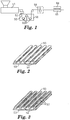
- a first embodiment method for forming a hook fastener portion is schematically illustrated in Fig. 1 .
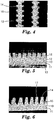
- the method includes first extruding a strip 50 shown in Fig. 2 of thermoplastic resin from an extruder 51 through a die 52 having an opening cut, for example, by electron discharge machining, shaped to form the strip 50 with a base 53 and elongate spaced ridges or ribs 54 projecting above an upper surface of the base layer 53 that have the cross sectional shape of the projections or hook members to be formed.
- the strip 50 is pulled around rollers 55 through a quench tank 56 filled with a cooling liquid (e.g., water), after which the ridges or ribs 54 (but not the base layer 53) are transversely slit or cut at spaced locations along their lengths by a cutter 58.
- the cutter forms discrete portions 57 of the ribs 54 having lengths corresponding to about the desired initial thicknesses of the cut portions to be formed into discrete projections , as is shown in Fig. 3 .
- Different cut angles or periods can also be used on the same strip, if desired.
- the cut can be at any desired angle, generally from 90° to 30° from the lengthwise extension of the ribs.
- the strip can be stretched prior to cutting to provide further molecular orientation to the polymers forming the ribs (increasing their ability to shrink when cut and heat treated) and/or reduce the size of the ribs and the resulting hook members formed by slitting of the ribs.
- the cutter 58 can cut using any conventional means such as reciprocating or rotating blades, lasers, or water jets, however preferably it cuts using blades oriented at an angle of about 60 to 80 degrees with respect to lengthwise extension of the ribs 54.
- the temperature and duration of the heating should be selected to cause shrinkage or thickness reduction of at least the top portion of the cut portion by from 5 to 90 percent.
- the non-contact heating source can include radiant, hot air, flame, UV, microwave, ultrasonics or focused IR heat lamps. This heat treating can be over the entire strip containing cut portions to form projections or hook portions or can be over only a portion or zone of the strip. Or different portions of the strip can be heat treated to more or less degrees of treatment to create projections having different characteristics. In this manner, it is possible, for example, to obtain on a single hook strip, hook containing areas with different levels of performance without the need to extrude different shaped rib profiles. This heat treatment can change projections or hook elements continuously or in a gradient across a region of the strip.
- the projections or hook elements can differ continuously across a defined area of the hook fastener portion. Further in this defined area, the projection or hook density can be the same in the different regions coupled with substantially the same film base layer caliper or thickness (e.g., 50 to 500 microns).
- the extruded strip can easily be made to have substantially the same basis weight and the same relative amount of material forming the ridges and base layer in all regions despite the difference in subsequent cutting and/or heat treating.
- the differential heat treatments can be along different rows or can cut across different rows, so that different types of projections or hooks, such as having different thicknesses or cross-sectional profiles, can be obtained in a single or multiple rows in the machine direction (lengthwise direction) or transverse direction of the hook strip.
- the heat treatment can be performed at any time following creation of the cut portions of the ridges or ribs, such that customized performance can be created without the need for modifying the basic strip extrusion manufacturing process.
- Figs. 4-7 show a hook member of the Fig. 3 cut hook after it has been heat treated to cause a reduction in the thickness 21 of the hook head portion 17.
- the other dimensions of the hook member can also change which is a result of conservation of mass.
- the height 20 generally increases a slight amount and the head portion width 23 increases as does the arm droop 24.
- the stem and head portions have a thickness dimension 21 that is nonuniform and tapers from the base to the head portion due to the incomplete heat treatment along the entire hook member 14.
- the untreated portion has a thickness up to the original thickness of the cut portion.
- the generally fully heat treated cut portion will have a uniform thickness 21 with a transition zone separating the untreated and treated portions.
- the incomplete heat treatment also results in variation of the thickness 21 of the hook head portion from the arm tip 39 to the arm portion 36, 37 adjacent the stem 15.
- Reduction in the projection or hook member thickness is caused by relaxation of at least the melt flow induced molecular orientation of the projection (e.g., the hook head and/or stem portion) which is in the machine direction, which generally corresponds to the thickness direction. Also, reduction in thickness can occur where there is stretch induced molecular orientation, as where ribs are stretched longitudinally prior to cutting.
- Melt flow induced molecular orientation is created by the melt extrusion process as polymer, under pressure and shear forces, is forced through the die orifice(s). The rib or ridge forming sections of the die create the melt flow induced molecular orientation in the formed ribs. This melt flow induced molecular orientation extends longitudinally or in the machine direction along the ribs or ridges.
- Stretch induced molecular orientation can be created by longitudinal stretching of the formed strips, regardless of whether they have melt flow induced orientation.
- the molecular orientation should extend generally in the thickness dimension of the cut rib portions, however, the molecular orientation can extend at an angle of from about 0 to 45 degrees to the cut portion thickness.
- the initial molecular orientation in the cut portions intended to form the projections or hook members is generally at least 10 percent, preferably 20 to 100 percent.
- the molecular orientation of the cut portions decrease and the resulting projection or hook member thickness dimension decreases.
- the amount of thickness reduction depends primarily on the amount of cut portion molecular orientation extending in the machine direction or hook thickness dimension.
- the heat treatment conditions such as time of treatment, temperature, the nature of the heat source and the like can also effect the cut portion thickness reduction.
- the reduction in cut portion, or projection thickness extends from the top portion, to the base or stem portion down the projection to the base, until the entire cut portion thickness has been reduced.
- the thickness reduction is substantially the same in the formed projection as one goes down the projection, when fully heat treated or partially heat treated to the same extent.
- the thickness dimension shrinks, the width of the treated portion generally increases, while the overall projection height increases slightly and for a hook the arm droop increases.
- the end result is a projection or hook member arranged closely spaced in a row where the spacing is one that can either, not be economically produced directly, or cannot be produced at all by conventional methods.
- the heat treated projection generally the hook head, and optionally stem, is also characterized by a molecular orientation level of less than 10 percent, preferably less than 5 percent whereas the base film layer orientation is substantially unreduced.
- the hook member stem or projection orientation immediately adjacent the base film layer will be 10 percent or higher, preferably 20 percent or higher.
- the heat treatment is generally carried out at a temperature near or above the polymer melt temperature. As the heat gets significantly above the polymer melt temperature, the treatment time decreases so as to minimize any actual melting of the polymer in the hook head portion or top of the projection.
- the heat treatment is carried out at a time sufficient to result in reduction of the thickness of the hook head, and/or stem, but not such that there is a significant deformation of the base layer or melt flow of the hook head portion or top of the projection. Heat treatment can also result in rounding of the hook head portion edges, improving tactile feel for use in garment applications.
- the invention projections can be arranged in very close proximity, for example, if closely spaced hooks or projections are desired, there can be 25/cm or more hooks or projections in a single row.
- a row is defined by hooks or projections that extend in a direction or extent and at least partially overlap in that direction or extent, preferably overlap by 50 percent or more most preferably 90 percent or more.
- the hooks or projections can be at least 30/cm even 50/cm or more up to 100/cm or possibly more.
- the overall density of the projections or hook members can be extremely high based on the closeness and width of the original rib members. If the rib members are closely spaced, extremely high hook densities are possible.
- Wider spacing between rib members can be created after the ribs are formed by stretch orientation of the base in a direction transverse to the rib members or hook rows. This can be beneficial to reduce the base layer thickness and made it more softer or less rigid while maintaining high number of projections in a row.
- Suitable polymeric materials from which the hook fastener portion can be made include thermoplastic resins capable of melt flow induced molecular orientation such as those comprising polyolefins, e.g. polypropylene and polyethylene, polyvinyl chloride, polystyrene, nylons, polyester such as polyethylene terephthalate and the like and copolymers and blends thereof.
- the resin is a polypropylene, polyethylene, polypropylene-polyethylene copolymer or blends thereof.
- the base layer is preferably a formed film which preferably is thick enough to allow it to be attached to a substrate by a desired means such as sonic welding, heat bonding, sewing or adhesives, including pressure sensitive or hot melt adhesives, and to firmly anchor the projections and provide resistance to tearing when subject to peel or shear forces.
- the base layer could be other extrudable shapes as would be known to those skilled in the art of extrusion.
- the base layer should not be so thick that it is stiffer than necessary.
- the film base layer has a Gurley stiffness of 10 to 2000, preferably 10 to 200 so as to allow it to be perceived as soft when used either by itself or laminated to a further carrier base layer structure such as a nonwoven, woven or film-type base layer, which carrier base layer should also be similarly soft for use in disposable garments or articles.
- the optimum base layer thickness will vary depending upon the resin from which the strip is made, but will generally be between 20 ⁇ m and 1000 ⁇ m, and is preferably 20 to 200 ⁇ m for softer base layers.
- the dimensions of the Examples and Comparative Example hook materials were measured using a Leica microscope equipped with a zoom lens at a magnification of approximately 25X. The samples were placed on a x-y moveable stage and measured via stage movement to the nearest micron. A minimum of 3 replicates were used and averaged for each dimension. As depicted generally in Figs. 7a and 7b , hook width is indicated by distance 23, hook height is indicated by distance 20, arm droop is indicated by distance 24, and hook thickness is indicated by distance 21. Hook thickness was measured at the top of the hook and approximately 300 microns down the stem from the top of the hook.
- the orientation and crystallinity is measured using X-ray diffraction techniques.
- Data is collected using a Bruker microdiffractometer (Bruker AXS, Madison, Wisconsin), using copper K ⁇ radiation, and HiSTARTM 2-dimensional detector registry of scattered radiation.
- the diffractometer is fitted with a graphite incident beam monochromator and a 200 micrometer pinhole collimator.
- the X-ray source consisted of a Rigaku RU200 (Rigaku USA, Danvers, MA) rotating anode and copper target operated at 50 kilovolts (kV) and 100 milliamperes (mA).
- Data is collected in transmission geometry with the detector centered at 0 degrees (2 ⁇ ) and a sample to detector distance of 6 cm.
- Test specimens are obtained by cutting thin sections of the hook materials in the machine direction after removing the hook arms.
- the incident beam is normal to the plane of the cut sections and thus is parallel to the cross direction of the extruded web.
- Three different positions are measured using a laser pointer and digital video camera alignment system. Measurements are taken near the center of the head portion 17, near the midpoint of the stem portion 15, and as close as possible to the bottom of the stem portion 17 just slightly above the surface 12 of the backing 11.
- the data is accumulated for 3600 seconds and corrected for detector sensitivity and spatial linearity using GADDSTM software (Bruker AXS Madison, Wisconsin).
- the crystallinity indices are calculated as the ratio of crystalline peak area to total peak area (crystalline + amorphous) within a 6 to 32 degree (2 ⁇ ) scattering angle range. A value of one represents 100 percent crystallinity and value of zero corresponds to completely amorphous material (0 percent crystallinity).
- the percent molecular orientation is calculated from the radial traces of the two-dimensional diffraction data. Background and amorphous intensities are assumed to be linear between the 2 ⁇ positions defined by traces (A) and (C) defined below. The background and amorphous intensities in trace (B) are interpolated for each element and subtracted from the trace to produce (B').
- Plot of trace (B') has constant intensity in absence of orientation or oscillatory intensity pattern when preferred orientation present.
- the magnitude of the crystalline fraction possessing no preferred orientation is defined by the minimum in the oscillatory pattern.
- the magnitude of the oriented crystalline fraction is defined by the intensity exceeding the oscillatory pattern minimum.
- the percent orientation is calculated by integration of the individual components from trace (B').
- B ' random i intensity value of minimum in oscillatory pattern
- B ' oriented i B ' i ⁇ B ' random i
- a mechanical fastener hook material web was made using the apparatus shown in Figure 1 .
- a polypropylene/polyethylene impact copolymer (SRC7-644, 1.5 MFI, Dow Chemical) pigmented with TiO2 (0.5%) was extruded with a 6.35 cm single screw extruder (24:1 L/D) using a barrel temperature profile of 177°C-232°C-246°C and a die temperature of approximately 235°C.
- the extrudate was extruded vertically downward through a die having an opening cut by electron discharge machining. After being shaped by the die, the extrudate is quenched in a water tank at a speed of 6.1 meter/min with the water being maintained at approximately 10°C.
- the web was then advanced through a cutting station where the ribs (but not the base layer) were transversely cut at an angle of 23 degrees measured from the transverse direction of the web.
- the spacing of the cuts was 305 microns.
- the precursor hook web described above was longitudinally (MD) drawn approximately 3.65 to 1 between two pairs of nip rolls to further separate the individual hook elements after the cutting step without any heat treatment of the hook side of the web. There were approximately 15 rows of ribs or cut hooks per centimeter crossweb after drawing. The dimensions of the resulting non heat-treated hook material are shown in Table 1 below.
- the precursor hook web described above was subjected to a non-contact heat treatment on the hook side of the web by passing said web underneath a perforated metal plate at a speed of 2.4 meter/min producing hook members having a profile substantially as shown in Fig. 7 .
- the hooks were approximately 46 cm from the perforated plate.
- the smooth base film side of the web was supported on a chill roll at approximately 149°C. After heat treatment the web was cooled by passing the web over a chill roll maintained at 11°C.
- Table 1 The dimensions of the resulting heat-treated hook material are shown in Table 1 below.
- the precursor hook web described above was subjected to a non-contact heat treatment on the hook side of the web using the following procedure.
- a 13 cm x 43 cm piece of web was placed onto a 13 cm x 43 cm steel plate(1.3 cm thick), hook-side up, and edge clamped to prevent the web from shrinking.
- Hot air from a Master brand hot air gun(14.5 amp) at 400°C was blown vertically down onto the web by passing the air gun uniformly over the web for about 20 seconds.
- the hot air gun vent was set at 50%.
- Table 1 The dimensions of the resulting heat-treated hook material are shown in Table 1 below.
Landscapes
- Slide Fasteners, Snap Fasteners, And Hook Fasteners (AREA)
- Extrusion Moulding Of Plastics Or The Like (AREA)
- Shaping By String And By Release Of Stress In Plastics And The Like (AREA)
Applications Claiming Priority (3)
| Application Number | Priority Date | Filing Date | Title |
|---|---|---|---|
| US321899 | 2002-12-17 | ||
| US10/321,899 US6814912B2 (en) | 2002-12-17 | 2002-12-17 | Heat treated high density structures |
| PCT/US2003/034994 WO2004060096A1 (en) | 2002-12-17 | 2003-11-03 | Heat treated high density structures |
Publications (2)
| Publication Number | Publication Date |
|---|---|
| EP1578223A1 EP1578223A1 (en) | 2005-09-28 |
| EP1578223B1 true EP1578223B1 (en) | 2017-12-20 |
Family
ID=32507151
Family Applications (1)
| Application Number | Title | Priority Date | Filing Date |
|---|---|---|---|
| EP03779460.9A Expired - Lifetime EP1578223B1 (en) | 2002-12-17 | 2003-11-03 | Heat treated high density structures |
Country Status (13)
| Country | Link |
|---|---|
| US (2) | US6814912B2 (zh) |
| EP (1) | EP1578223B1 (zh) |
| JP (2) | JP4732760B2 (zh) |
| KR (1) | KR20050085651A (zh) |
| CN (1) | CN1809296B (zh) |
| AR (1) | AR042786A1 (zh) |
| AU (1) | AU2003285139A1 (zh) |
| BR (1) | BR0317073A (zh) |
| MX (1) | MXPA05006387A (zh) |
| RU (1) | RU2005115838A (zh) |
| TR (1) | TR201802816T4 (zh) |
| TW (1) | TW200508018A (zh) |
| WO (1) | WO2004060096A1 (zh) |
Families Citing this family (25)
| Publication number | Priority date | Publication date | Assignee | Title |
|---|---|---|---|---|
| US7052636B2 (en) * | 2002-01-15 | 2006-05-30 | 3M Innovative Properties Company | Heat treated profile extruded hook |
| US6814912B2 (en) * | 2002-12-17 | 2004-11-09 | 3M Innovative Properties Company | Heat treated high density structures |
| US6982055B2 (en) * | 2003-03-25 | 2006-01-03 | 3M Innovative Properties Company | Multiheaded hook |
| US20050132544A1 (en) * | 2003-12-23 | 2005-06-23 | Jayshree Seth | Split hook fastener |
| US7897078B2 (en) * | 2004-03-09 | 2011-03-01 | 3M Innovative Properties Company | Methods of manufacturing a stretched mechanical fastening web laminate |
| EP1669001A1 (en) * | 2004-12-10 | 2006-06-14 | 3M Innovative Properties Company | Strip of male fastening means, patch cut therefrom, and fastening tape tab comprising such patch |
| WO2007118036A2 (en) * | 2006-04-03 | 2007-10-18 | 3M Innovative Properties Company | Human floatation device configured for radio frequency identification |
| US20070232164A1 (en) * | 2006-04-03 | 2007-10-04 | 3M Innovative Properties Company | Tamper-evident life vest package |
| US20070229268A1 (en) * | 2006-04-03 | 2007-10-04 | 3M Innovative Properties Company | Vehicle inspection using radio frequency identification (rfid) |
| US9745103B2 (en) | 2006-05-05 | 2017-08-29 | Illinois Tool Works Inc. | Wide mouth gusseted pouches |
| DE102006047139A1 (de) * | 2006-10-05 | 2008-04-10 | Robert Bosch Gmbh | Schleifvorrichtung mit lösbar verbundenem Schleifelement |
| US7954208B2 (en) * | 2007-10-31 | 2011-06-07 | Avery Dennison Corporation | Fastening member for a molded article |
| US8256068B2 (en) * | 2007-11-16 | 2012-09-04 | Panduit Corp. | Microhook fastener apparatus |
| US9138957B2 (en) | 2010-06-21 | 2015-09-22 | 3M Innovative Properties Company | Slit hook strips and laminates and articles containing the same |
| US8973225B2 (en) | 2010-12-21 | 2015-03-10 | 3M Innovative Properties Company | Structured surface with multiple-post caps and method of making the same |
| US8845943B2 (en) | 2010-12-21 | 2014-09-30 | 3M Innovative Properties Company | Method of making a structured surface and article therefrom |
| US20120260401A1 (en) * | 2011-04-12 | 2012-10-18 | Darryl Moskowitz | Releasable securement device |
| KR102245694B1 (ko) | 2011-09-16 | 2021-04-27 | 쓰리엠 이노베이티브 프로퍼티즈 캄파니 | 기계식 체결구, 체결 시스템, 및 일회용 흡수 용품 |
| US9084701B2 (en) | 2011-11-10 | 2015-07-21 | The Procter & Gamble Company | Absorbent articles with hook and loop fastening systems |
| JP2015205032A (ja) * | 2014-04-21 | 2015-11-19 | スリーエム イノベイティブ プロパティズ カンパニー | ファスニングシステム |
| US10341258B2 (en) | 2016-05-02 | 2019-07-02 | Ciena Corporation | Dynamic adjustment of connection priority in networks |
| WO2019166935A1 (en) | 2018-02-28 | 2019-09-06 | 3M Innovative Properties Company | Coextruded polymeric article and method of making the same |
| EP3758911B1 (en) | 2018-02-28 | 2022-03-30 | 3M Innovative Properties Company | Coextruded polymeric article and method of making the same |
| US20210371137A1 (en) * | 2020-05-26 | 2021-12-02 | Illinois Tool Works Inc. | Closure strips of resealable enclosures and methods of terminating the closure strips |
| US11931945B2 (en) * | 2020-10-20 | 2024-03-19 | Ford Global Technologies, Llc | Extruded sealed fastener |
Family Cites Families (36)
| Publication number | Priority date | Publication date | Assignee | Title |
|---|---|---|---|---|
| US3266113A (en) | 1963-10-07 | 1966-08-16 | Minnesota Mining & Mfg | Interreacting articles |
| US3557413A (en) | 1968-09-23 | 1971-01-26 | William H Engle | Nonmechanical closure |
| FR2082591A5 (en) | 1970-03-20 | 1971-12-10 | Velcro France | Separable plastic fixing bands - prepd by continuous extrusion and subvision |
| ES389609A1 (es) * | 1971-03-26 | 1971-12-16 | Navas Albareda De | Procedimiento para la fabricacion continua de elementos mo-nobloques dotados de protuberancias de agarre. |
| AT333222B (de) | 1971-03-26 | 1976-11-10 | Repla Int | Verfahren und einrichtung zur herstellung eines klettenverschlusses |
| US4001366A (en) | 1972-01-03 | 1977-01-04 | Ingrip Fasteners Inc. | Method for making self-gripping devices having integral trains of gripping elements |
| ES453167A1 (es) | 1976-11-10 | 1977-11-16 | Velero Espanola S A | Mejoras en los procedimientos de fabricacion continua de e- lementos monobloques autofijables. |
| US4497860A (en) * | 1978-12-18 | 1985-02-05 | Minnesota Mining And Manufacturing Company | Imageable prismatic array |
| US5011642A (en) * | 1987-06-05 | 1991-04-30 | Minnesota Mining And Manufacturing Company | Method of making extruded article |
| US4894060A (en) * | 1988-01-11 | 1990-01-16 | Minnesota Mining And Manufacturing Company | Disposable diaper with improved hook fastener portion |
| JPH0217006A (ja) | 1988-07-04 | 1990-01-22 | Kuraray Co Ltd | 面フアスナーの製造法 |
| JP2810388B2 (ja) * | 1988-10-27 | 1998-10-15 | 旭化成工業株式会社 | ロケットモータ点火装置用容器 |
| US5176670A (en) * | 1988-12-20 | 1993-01-05 | Kimberly-Clark Corporation | Disposable diaper with improved mechanical fastening system |
| US5230851A (en) * | 1989-01-31 | 1993-07-27 | The Procter & Gamble Company | Process of manufacturing a refastenable mechanical fastening system |
| US5040275A (en) * | 1990-06-01 | 1991-08-20 | Minnesota Mining And Manufacturing Company | Strip material used for forming fasteners |
| US5679302A (en) * | 1990-09-21 | 1997-10-21 | Minnesota Mining And Manufacturing Company | Method for making a mushroom-type hook strip for a mechanical fastener |
| US5315740A (en) | 1992-08-20 | 1994-05-31 | Velcro Industries, B.V. | Hook for hook and loop fasteners |
| JP3392887B2 (ja) * | 1992-10-16 | 2003-03-31 | ミネソタ マイニング アンド マニュファクチャリング カンパニー | 相互係合式ファスナー |
| US5505747A (en) * | 1994-01-13 | 1996-04-09 | Minnesota Mining And Manufacturing Company | Method of making an abrasive article |
| US5900350A (en) * | 1996-06-06 | 1999-05-04 | Velcro Industries B.V. | Molding methods, molds and products |
| US5953797A (en) * | 1996-10-09 | 1999-09-21 | Velcro Industries B.V. | Hook fasteners and methods of manufacture |
| US6039911A (en) * | 1997-01-09 | 2000-03-21 | 3M Innovative Properties Company | Method for capping stem fasteners |
| US5945131A (en) * | 1997-04-16 | 1999-08-31 | Velcro Industries B.V. | Continuous molding of fastener products and the like and products produced thereby |
| JP3505074B2 (ja) | 1998-01-22 | 2004-03-08 | Ykk株式会社 | 成形面ファスナー |
| US6066281A (en) | 1998-06-16 | 2000-05-23 | Velcro Industries B.V. | Fastener products and their production |
| US6303062B1 (en) | 1999-04-13 | 2001-10-16 | 3M Innovative Properties Company | Mechanical fastener and method for making the same |
| US6756327B2 (en) * | 2000-10-31 | 2004-06-29 | Kimberly-Clark Worldwide, Inc. | Loop fastening component made from thermally retracted materials |
| US6484371B1 (en) * | 2001-02-27 | 2002-11-26 | 3M Innovative Properties Company | High strength, flexible, light weight hook and loop bundling straps |
| US6730069B2 (en) * | 2001-07-05 | 2004-05-04 | Kimberly-Clark Worldwide, Inc. | Cloth-like mechanical fastener |
| AU2002367012A1 (en) | 2002-01-15 | 2003-07-30 | 3M Innovative Properties Company | Heat treated extruded hook fastener |
| US20030145440A1 (en) * | 2002-01-15 | 2003-08-07 | 3M Innovative Properties Company | Heat treated profile extruded hook |
| US20030182776A1 (en) * | 2002-01-15 | 2003-10-02 | 3M Innovative Properties Company | Heat treated profile extruded hook |
| US7052636B2 (en) * | 2002-01-15 | 2006-05-30 | 3M Innovative Properties Company | Heat treated profile extruded hook |
| US6687962B2 (en) * | 2002-01-16 | 2004-02-10 | Velcro Industries B.V. | Fastener element patterning |
| US6684464B1 (en) * | 2002-08-07 | 2004-02-03 | 3M Innovative Properties Company | Bundling strap |
| US6814912B2 (en) * | 2002-12-17 | 2004-11-09 | 3M Innovative Properties Company | Heat treated high density structures |
-
2002
- 2002-12-17 US US10/321,899 patent/US6814912B2/en not_active Expired - Fee Related
-
2003
- 2003-11-03 JP JP2004564855A patent/JP4732760B2/ja not_active Expired - Fee Related
- 2003-11-03 EP EP03779460.9A patent/EP1578223B1/en not_active Expired - Lifetime
- 2003-11-03 KR KR1020057010888A patent/KR20050085651A/ko not_active Application Discontinuation
- 2003-11-03 WO PCT/US2003/034994 patent/WO2004060096A1/en active Application Filing
- 2003-11-03 MX MXPA05006387A patent/MXPA05006387A/es active IP Right Grant
- 2003-11-03 RU RU2005115838/12A patent/RU2005115838A/ru not_active Application Discontinuation
- 2003-11-03 CN CN2003801066129A patent/CN1809296B/zh not_active Expired - Fee Related
- 2003-11-03 AU AU2003285139A patent/AU2003285139A1/en not_active Abandoned
- 2003-11-03 TR TR2018/02816T patent/TR201802816T4/tr unknown
- 2003-11-03 BR BR0317073-0A patent/BR0317073A/pt not_active IP Right Cessation
- 2003-12-08 TW TW092134552A patent/TW200508018A/zh unknown
- 2003-12-15 AR ARP030104623A patent/AR042786A1/es active IP Right Grant
-
2004
- 2004-02-25 US US10/786,486 patent/US7007351B2/en not_active Expired - Lifetime
-
2010
- 2010-12-21 JP JP2010284676A patent/JP2011072810A/ja active Pending
Also Published As
| Publication number | Publication date |
|---|---|
| RU2005115838A (ru) | 2006-03-20 |
| JP4732760B2 (ja) | 2011-07-27 |
| CN1809296B (zh) | 2012-11-07 |
| US6814912B2 (en) | 2004-11-09 |
| JP2006510458A (ja) | 2006-03-30 |
| US20040111844A1 (en) | 2004-06-17 |
| TW200508018A (en) | 2005-03-01 |
| US7007351B2 (en) | 2006-03-07 |
| WO2004060096A1 (en) | 2004-07-22 |
| BR0317073A (pt) | 2005-10-25 |
| AU2003285139A1 (en) | 2004-07-29 |
| TR201802816T4 (tr) | 2018-03-21 |
| EP1578223A1 (en) | 2005-09-28 |
| MXPA05006387A (es) | 2005-08-26 |
| US20040163222A1 (en) | 2004-08-26 |
| KR20050085651A (ko) | 2005-08-29 |
| CN1809296A (zh) | 2006-07-26 |
| JP2011072810A (ja) | 2011-04-14 |
| AR042786A1 (es) | 2005-07-06 |
Similar Documents
| Publication | Publication Date | Title |
|---|---|---|
| EP1578223B1 (en) | Heat treated high density structures | |
| EP1615521B1 (en) | Multiheaded hook | |
| EP1467639B1 (en) | Heat treated profile extruded hook | |
| US7670522B2 (en) | Reinforced hook web | |
| US20040068848A1 (en) | Heat treated profile extruded hook | |
| US20030182776A1 (en) | Heat treated profile extruded hook | |
| WO2003059108A2 (en) | Heat treated extruded hook fastener |
Legal Events
| Date | Code | Title | Description |
|---|---|---|---|
| PUAI | Public reference made under article 153(3) epc to a published international application that has entered the european phase |
Free format text: ORIGINAL CODE: 0009012 |
|
| 17P | Request for examination filed |
Effective date: 20050712 |
|
| AK | Designated contracting states |
Kind code of ref document: A1 Designated state(s): AT BE BG CH CY CZ DE DK EE ES FI FR GB GR HU IE IT LI LU MC NL PT RO SE SI SK TR |
|
| AX | Request for extension of the european patent |
Extension state: AL LT LV MK |
|
| DAX | Request for extension of the european patent (deleted) | ||
| 17Q | First examination report despatched |
Effective date: 20081016 |
|
| STAA | Information on the status of an ep patent application or granted ep patent |
Free format text: STATUS: EXAMINATION IS IN PROGRESS |
|
| GRAP | Despatch of communication of intention to grant a patent |
Free format text: ORIGINAL CODE: EPIDOSNIGR1 |
|
| STAA | Information on the status of an ep patent application or granted ep patent |
Free format text: STATUS: GRANT OF PATENT IS INTENDED |
|
| INTG | Intention to grant announced |
Effective date: 20170601 |
|
| GRAS | Grant fee paid |
Free format text: ORIGINAL CODE: EPIDOSNIGR3 |
|
| GRAA | (expected) grant |
Free format text: ORIGINAL CODE: 0009210 |
|
| STAA | Information on the status of an ep patent application or granted ep patent |
Free format text: STATUS: THE PATENT HAS BEEN GRANTED |
|
| AK | Designated contracting states |
Kind code of ref document: B1 Designated state(s): AT BE BG CH CY CZ DE DK EE ES FI FR GB GR HU IE IT LI LU MC NL PT RO SE SI SK TR |
|
| REG | Reference to a national code |
Ref country code: GB Ref legal event code: FG4D |
|
| REG | Reference to a national code |
Ref country code: CH Ref legal event code: EP |
|
| REG | Reference to a national code |
Ref country code: IE Ref legal event code: FG4D |
|
| REG | Reference to a national code |
Ref country code: AT Ref legal event code: REF Ref document number: 955564 Country of ref document: AT Kind code of ref document: T Effective date: 20180115 |
|
| REG | Reference to a national code |
Ref country code: DE Ref legal event code: R096 Ref document number: 60350864 Country of ref document: DE |
|
| REG | Reference to a national code |
Ref country code: NL Ref legal event code: MP Effective date: 20171220 |
|
| PG25 | Lapsed in a contracting state [announced via postgrant information from national office to epo] |
Ref country code: SE Free format text: LAPSE BECAUSE OF FAILURE TO SUBMIT A TRANSLATION OF THE DESCRIPTION OR TO PAY THE FEE WITHIN THE PRESCRIBED TIME-LIMIT Effective date: 20171220 Ref country code: FI Free format text: LAPSE BECAUSE OF FAILURE TO SUBMIT A TRANSLATION OF THE DESCRIPTION OR TO PAY THE FEE WITHIN THE PRESCRIBED TIME-LIMIT Effective date: 20171220 |
|
| REG | Reference to a national code |
Ref country code: AT Ref legal event code: MK05 Ref document number: 955564 Country of ref document: AT Kind code of ref document: T Effective date: 20171220 |
|
| PG25 | Lapsed in a contracting state [announced via postgrant information from national office to epo] |
Ref country code: BG Free format text: LAPSE BECAUSE OF FAILURE TO SUBMIT A TRANSLATION OF THE DESCRIPTION OR TO PAY THE FEE WITHIN THE PRESCRIBED TIME-LIMIT Effective date: 20180320 Ref country code: GR Free format text: LAPSE BECAUSE OF FAILURE TO SUBMIT A TRANSLATION OF THE DESCRIPTION OR TO PAY THE FEE WITHIN THE PRESCRIBED TIME-LIMIT Effective date: 20180321 |
|
| PG25 | Lapsed in a contracting state [announced via postgrant information from national office to epo] |
Ref country code: NL Free format text: LAPSE BECAUSE OF FAILURE TO SUBMIT A TRANSLATION OF THE DESCRIPTION OR TO PAY THE FEE WITHIN THE PRESCRIBED TIME-LIMIT Effective date: 20171220 |
|
| PG25 | Lapsed in a contracting state [announced via postgrant information from national office to epo] |
Ref country code: ES Free format text: LAPSE BECAUSE OF FAILURE TO SUBMIT A TRANSLATION OF THE DESCRIPTION OR TO PAY THE FEE WITHIN THE PRESCRIBED TIME-LIMIT Effective date: 20171220 Ref country code: CY Free format text: LAPSE BECAUSE OF FAILURE TO SUBMIT A TRANSLATION OF THE DESCRIPTION OR TO PAY THE FEE WITHIN THE PRESCRIBED TIME-LIMIT Effective date: 20171220 Ref country code: CZ Free format text: LAPSE BECAUSE OF FAILURE TO SUBMIT A TRANSLATION OF THE DESCRIPTION OR TO PAY THE FEE WITHIN THE PRESCRIBED TIME-LIMIT Effective date: 20171220 Ref country code: EE Free format text: LAPSE BECAUSE OF FAILURE TO SUBMIT A TRANSLATION OF THE DESCRIPTION OR TO PAY THE FEE WITHIN THE PRESCRIBED TIME-LIMIT Effective date: 20171220 Ref country code: SK Free format text: LAPSE BECAUSE OF FAILURE TO SUBMIT A TRANSLATION OF THE DESCRIPTION OR TO PAY THE FEE WITHIN THE PRESCRIBED TIME-LIMIT Effective date: 20171220 |
|
| PG25 | Lapsed in a contracting state [announced via postgrant information from national office to epo] |
Ref country code: AT Free format text: LAPSE BECAUSE OF FAILURE TO SUBMIT A TRANSLATION OF THE DESCRIPTION OR TO PAY THE FEE WITHIN THE PRESCRIBED TIME-LIMIT Effective date: 20171220 Ref country code: RO Free format text: LAPSE BECAUSE OF FAILURE TO SUBMIT A TRANSLATION OF THE DESCRIPTION OR TO PAY THE FEE WITHIN THE PRESCRIBED TIME-LIMIT Effective date: 20171220 Ref country code: IT Free format text: LAPSE BECAUSE OF FAILURE TO SUBMIT A TRANSLATION OF THE DESCRIPTION OR TO PAY THE FEE WITHIN THE PRESCRIBED TIME-LIMIT Effective date: 20171220 |
|
| REG | Reference to a national code |
Ref country code: FR Ref legal event code: PLFP Year of fee payment: 16 |
|
| REG | Reference to a national code |
Ref country code: DE Ref legal event code: R097 Ref document number: 60350864 Country of ref document: DE |
|
| PLBE | No opposition filed within time limit |
Free format text: ORIGINAL CODE: 0009261 |
|
| STAA | Information on the status of an ep patent application or granted ep patent |
Free format text: STATUS: NO OPPOSITION FILED WITHIN TIME LIMIT |
|
| 26N | No opposition filed |
Effective date: 20180921 |
|
| PG25 | Lapsed in a contracting state [announced via postgrant information from national office to epo] |
Ref country code: DK Free format text: LAPSE BECAUSE OF FAILURE TO SUBMIT A TRANSLATION OF THE DESCRIPTION OR TO PAY THE FEE WITHIN THE PRESCRIBED TIME-LIMIT Effective date: 20171220 |
|
| PG25 | Lapsed in a contracting state [announced via postgrant information from national office to epo] |
Ref country code: SI Free format text: LAPSE BECAUSE OF FAILURE TO SUBMIT A TRANSLATION OF THE DESCRIPTION OR TO PAY THE FEE WITHIN THE PRESCRIBED TIME-LIMIT Effective date: 20171220 |
|
| REG | Reference to a national code |
Ref country code: CH Ref legal event code: PL |
|
| GBPC | Gb: european patent ceased through non-payment of renewal fee |
Effective date: 20181103 |
|
| PG25 | Lapsed in a contracting state [announced via postgrant information from national office to epo] |
Ref country code: LU Free format text: LAPSE BECAUSE OF NON-PAYMENT OF DUE FEES Effective date: 20181103 Ref country code: MC Free format text: LAPSE BECAUSE OF FAILURE TO SUBMIT A TRANSLATION OF THE DESCRIPTION OR TO PAY THE FEE WITHIN THE PRESCRIBED TIME-LIMIT Effective date: 20171220 |
|
| REG | Reference to a national code |
Ref country code: BE Ref legal event code: MM Effective date: 20181130 |
|
| REG | Reference to a national code |
Ref country code: IE Ref legal event code: MM4A |
|
| PG25 | Lapsed in a contracting state [announced via postgrant information from national office to epo] |
Ref country code: CH Free format text: LAPSE BECAUSE OF NON-PAYMENT OF DUE FEES Effective date: 20181130 Ref country code: LI Free format text: LAPSE BECAUSE OF NON-PAYMENT OF DUE FEES Effective date: 20181130 |
|
| PG25 | Lapsed in a contracting state [announced via postgrant information from national office to epo] |
Ref country code: IE Free format text: LAPSE BECAUSE OF NON-PAYMENT OF DUE FEES Effective date: 20181103 |
|
| PG25 | Lapsed in a contracting state [announced via postgrant information from national office to epo] |
Ref country code: BE Free format text: LAPSE BECAUSE OF NON-PAYMENT OF DUE FEES Effective date: 20181130 |
|
| PG25 | Lapsed in a contracting state [announced via postgrant information from national office to epo] |
Ref country code: GB Free format text: LAPSE BECAUSE OF NON-PAYMENT OF DUE FEES Effective date: 20181103 |
|
| PG25 | Lapsed in a contracting state [announced via postgrant information from national office to epo] |
Ref country code: PT Free format text: LAPSE BECAUSE OF FAILURE TO SUBMIT A TRANSLATION OF THE DESCRIPTION OR TO PAY THE FEE WITHIN THE PRESCRIBED TIME-LIMIT Effective date: 20171220 |
|
| PG25 | Lapsed in a contracting state [announced via postgrant information from national office to epo] |
Ref country code: HU Free format text: LAPSE BECAUSE OF FAILURE TO SUBMIT A TRANSLATION OF THE DESCRIPTION OR TO PAY THE FEE WITHIN THE PRESCRIBED TIME-LIMIT; INVALID AB INITIO Effective date: 20031103 |
|
| PGFP | Annual fee paid to national office [announced via postgrant information from national office to epo] |
Ref country code: DE Payment date: 20211020 Year of fee payment: 19 |
|
| PGFP | Annual fee paid to national office [announced via postgrant information from national office to epo] |
Ref country code: FR Payment date: 20211020 Year of fee payment: 19 |
|
| REG | Reference to a national code |
Ref country code: DE Ref legal event code: R119 Ref document number: 60350864 Country of ref document: DE |
|
| PG25 | Lapsed in a contracting state [announced via postgrant information from national office to epo] |
Ref country code: DE Free format text: LAPSE BECAUSE OF NON-PAYMENT OF DUE FEES Effective date: 20230601 |
|
| PG25 | Lapsed in a contracting state [announced via postgrant information from national office to epo] |
Ref country code: FR Free format text: LAPSE BECAUSE OF NON-PAYMENT OF DUE FEES Effective date: 20221130 |