EP1577845B1 - Coin dispensing apparatus with safe system - Google Patents
Coin dispensing apparatus with safe system Download PDFInfo
- Publication number
- EP1577845B1 EP1577845B1 EP05001192A EP05001192A EP1577845B1 EP 1577845 B1 EP1577845 B1 EP 1577845B1 EP 05001192 A EP05001192 A EP 05001192A EP 05001192 A EP05001192 A EP 05001192A EP 1577845 B1 EP1577845 B1 EP 1577845B1
- Authority
- EP
- European Patent Office
- Prior art keywords
- coin
- coins
- safe
- dispensing
- dispensing apparatus
- Prior art date
- Legal status (The legal status is an assumption and is not a legal conclusion. Google has not performed a legal analysis and makes no representation as to the accuracy of the status listed.)
- Ceased
Links
- 230000001603 reducing effect Effects 0.000 description 4
- 230000005540 biological transmission Effects 0.000 description 1
- 230000001419 dependent effect Effects 0.000 description 1
- 238000011161 development Methods 0.000 description 1
- 230000018109 developmental process Effects 0.000 description 1
- 230000005284 excitation Effects 0.000 description 1
- 230000002265 prevention Effects 0.000 description 1
- 230000035939 shock Effects 0.000 description 1
- 229910001220 stainless steel Inorganic materials 0.000 description 1
- 239000010935 stainless steel Substances 0.000 description 1
- 230000032258 transport Effects 0.000 description 1
Images


Classifications
-
- G—PHYSICS
- G07—CHECKING-DEVICES
- G07D—HANDLING OF COINS OR VALUABLE PAPERS, e.g. TESTING, SORTING BY DENOMINATIONS, COUNTING, DISPENSING, CHANGING OR DEPOSITING
- G07D9/00—Counting coins; Handling of coins not provided for in the other groups of this subclass
- G07D9/008—Feeding coins from bulk
-
- G—PHYSICS
- G07—CHECKING-DEVICES
- G07D—HANDLING OF COINS OR VALUABLE PAPERS, e.g. TESTING, SORTING BY DENOMINATIONS, COUNTING, DISPENSING, CHANGING OR DEPOSITING
- G07D1/00—Coin dispensers
-
- G—PHYSICS
- G07—CHECKING-DEVICES
- G07D—HANDLING OF COINS OR VALUABLE PAPERS, e.g. TESTING, SORTING BY DENOMINATIONS, COUNTING, DISPENSING, CHANGING OR DEPOSITING
- G07D9/00—Counting coins; Handling of coins not provided for in the other groups of this subclass
Definitions
- This invention is related to a coin dispensing apparatus which can be attached or detached to or from a coin handling apparatus. Especially, this invention is related to a coin dispensing apparatus with a safe system in which, when the coin dispensing apparatus is detached from the coin handling apparatus, the coins can't be stolen from the coin dispensing apparatus. More especially, this invention is related to a coin dispensing apparatus with a safe system on the grounds of a simple mechanism. Also, the coin handling apparatus is for example: a money changer, an automatic changer or etc. In this specification, the term "coin” includes generally a coin, a token for amusement and a medium which has the same function.
- a hopper In first prior art, two hoppers which include a rotating disk with through holes are located in a safe unit which is a box whose lid can be locked (for example patent document No. 1, Japanese Patent No. 2514825 (figures 1-3 and pages 2-4)).
- a hopper In second prior art (the patent document No. 2, Japanese Laid open Patent 11-250301 (figures 1-5 and pages 2-3)), a hopper includes a rotating disk with through holes which is driven by an electric motor and is located at the bottom of a storing bowl which has an upper opening, and the hopper dispenses coins one by one.
- the shutter is automatically opened, and can receive the received coins of the charging apparatus.
- the shutter isn't automatically closed.
- the dispensing slot for the coins of the hopper and the driving section of the rotating disk are exposed. Accordingly, the rotating disk can be rotated by anybody. As a result, the coins can be stolen.
- a coin dispensing apparatus having a safe system comprising a coin dispensing apparatus which includes a rotating disc with throughholes which is located at the bottom of a coin storing bowl with an upper opening and which is rotated by an electric motor through a transfer mechanism. Further, a safe cover which is built in the coin dispensing apparatus and which can be detached from a coin handling apparatus is provided and includes a dispensing slot for dispensing dispensed coins from the dispensing apparatus.
- the first purpose of this present invention is to provide a coin dispensing apparatus with a safe system which can prevent coins from being stolen.
- the second purpose of this invention is to provide a coin dispensing apparatus with a safe system which can prevent coins from being stolen, which also is simple and inexpensive. This object is achieved by the features of claim 1. Further advantageous developments are the subject-matters of the dependent claims.
- a coin dispensing apparatus with a safe system comprises of:
- the coin dispensing apparatus is built in the safe cover.
- the safe cover When the safe cover is drawn out from the coin handling apparatus, the upper opening is covered with the safe cover. Therefore the bulk of coins in the storing bowl of the coin dispensing apparatus can't be stolen.
- the rotating disk for dispensing the coins can't be rotated, because the rotating disk is stopped by the non-operating unit. Therefore the rotating disk can' t be rotated from the coin dispensing slot. As a result, the stored coins in the storing bowl aren't dispensed, and the coins aren't stolen.
- the non-operating unit is a rotation stopping unit for locking said rotating disk.
- the rotating disk is non-rotatable by the non-operating unit. Therefore when the rotating disk receives a rotating force from the inserted object from the coin dispensing slot of the safe cover, the rotating disk is non-rotatable, and the coins in the coin dispensing apparatus aren't dispensed.
- the motor is an electric motor
- said rotating disk is driven by said motor through a transfer mechanism
- said non-operating unit is a stopping tooth which is engageable with said transfer mechanism.
- said non-operating unit is a shutter which shuts the dispensing slot for coin.
- the coin dispensing slot of the safe cover is closed by the shutter. Accordingly, other objects can't be inserted into the dispensing slot.
- the rotating disk is the same as the locked rotating disk. In other words, the rotating disk can't be rotated by other forces, and the stored coins in the coin dispensing apparatus aren't dispensed.
- an opening of a connector for operating said motor is located at the front surface of said safe cover to said coin handling apparatus.
- the coin dispensing slot and the opening of the connector for providing the driving source to the motor are located at the front surface of the safe cover.
- the coin receiving slot from the coin dispensing slot and the connector are located at the coin handling apparatus corresponding to the opening and the connector. Therefore, when the safe cover is moved towards the inside of the coin handling apparatus, the connectors are connected, and the coin slots are automatically coupled. As a result, it is convenient.
- a coin dispensing apparatus with a safe system comprises of:
- the coins are Japanese Yen, however other coins can be used, for example US dollar coins or Euro coins.
- the coin handling apparatus 101 is an automatic changing machine or anATM which dispenses a predetermined domination and a predetermined quantity based on a directing signal.
- Coin dispensing apparatus 50 with safe system for 50 Yen, coin dispensing apparatus 100 with safe system for 100 Yen, coin dispensing apparatus 10 with safe system for 10 Yen and coin dispensing apparatus 1 with safe system are located at safe areas 112,114,116 and 118 which are aligned perpendicular. Safe areas 112,114,116 and 118 are divided by separating plates 102, 104, 006 and 108 which are located at a predetermined distance perpendicular.
- Coin dispensing apparatus 50, 100, 10 and 1 with safe system can be detached from the safe areas 112,114,116 and 118.
- Coin dispensing apparatus 50, 100, 10 and 1 with safe system can be changed in their positions.
- dispensing apparatuses with a safe system which dispenses a lot in quantity are located at lower positions and those except for the above-mentioned dispensing apparatuses are located at upper positions.
- safe type dispensing apparatuses which dispense light weight coins are located at lower positions and the dispensing apparatuses for heavier coins are located at the upper positions. In these cases, the dispensing time for finishing all coins is as short as possible.
- Coin dispensing apparatuses 50, 100, 10 and 1 dispense the coins into falling duct 120 which is located beside the safe area.
- the dispensed coins fall in the falling duct 120, afterwards the coins fall onto a lateral direction transporting unit 122 which is located under the duct 120.
- the lateral direction transporting unit 122 is a belt.
- the fallen coins are transported towards the lateral direction by the lateral direction transporting unit 122 and are received by a lifting unit 124. Afterwards, the coins are lifted upwards by the lifting unit 124.
- the lateral direction transporting unit 122 has a function which transports the fallen coins and move them away from the falling duct 120. Therefore, the fallen coins can be moved either obliquely upwards or obliquely downwards.
- the coins lifted by the lifting unit 124 are dispensed into a receiving slot 126 which is bowl shaped.
- Dispensing slots 132, 134, 136 and 138 of safe areas 112, 114, 116 and 118 to the falling duct 120 are located at one-side towards the right at a plate 205 for defining the falling duct 120 as shown in figure 1(B).
- a second slanting guide plate 143 which extends at a right angle to the first slanting guide plate 142 is located below the first slanting guide plate 142 which is located at the uppermost position.
- a further second slanting guide plate 145 which extends at a right angle to the first slanting guide plate 144 is located below the first slanting guide plate 144 which is located at second upper position.
- First slanting guide plates 142,144,146,148 and second slanting guide plates 143,145 are a speed reducing unit 152 for reducing the falling speed where the dispensed coins fall onto the lateral direction transporting unit.
- the dispensed coins which were dispensed from each dispensing slot 132,134,136,138 are approximately level. Accordingly, the dispensed coins have contact with the surfaces and are guided by the first slanting guide plates 142,144,146,148 and the second slanting guide plates 143,145.
- the coin speed is reduced by the friction between the guide plates and the coins. Afterwards, the coins fall from the ends of the slanting guide plates 143,145,146,148 which are located below dispensing slots 143,134,136,138. Accordingly, the falling speed onto the lateral direction transporting unit 122 is reduced. Therefore, the coin's dance bounce on the rebounding is reduced. As a result, the coins are transported quickly.
- the speed reducing unit 152 is structured where the second slanting guide plates 143, 145 are located under the first slanting guiding plates 142,144 and are like a zigzag as shown in figure 2.
- the structure is desirable, because the speeds reducing effect is increased.
- the dispensed coins which are dispensed by the coin dispensing apparatus 50, 100 fall from the lower ends of the second slanting guiding guide plates 143,145 and fall onto a third slanting guide plate 147. The coins are guided towards the side by the third slanting guide plate 147, and fall onto the lateral direction transporting unit 122.
- the dispensed coins which are dispensed by the coin dispensing apparatuses 10,1 which are located lower fall directly onto the lateral direction transporting unit 122 from the first slanting guide plates 146,148. Accordingly, the falling position of the coins is dispersed. As a result, the coins are lifted smoothly by the lifting unit 124.
- Coin dispensing apparatuses with safe systems 50,100,10,1 which are in the present invention is explained referring to figures 3-7.
- Coin dispensing apparatuses with safe systems 50,100,10,1 have principally the same structure. Therefore, the coin dispensing apparatus 50 which is located at the uppermost position is explained on behalf of the other apparatuses.
- Coin dispensing apparatuses with safe systems 50 includes a coin hopper with a rotating disk 160, a safe cover 164 which is built in the coin hopper 162 and a non-operating unit 166 for the rotating disk 160.
- the coin hopper 162 includes a coin storing bowl 170, the rotating disk 160, a motor 174 and a transmitting mechanism 176.
- a coin storing bowl 170 is like a cylinder and can be detached from the upper surface of a base 168.
- the rotating disk 160 is located in a circle hole 172 which is located at the bottom of the bowl 170.
- the motor 174 (an electric motor in this embodiment) is fixed at the upper surface of the base 168.
- the transmitting mechanism 176 transmits the rotation from the motor 174 to the rotating disk 160 (shown in figure 7).
- the motor 174 can be changed to either an air-motor, anoil-motor or etc.
- An electric motor is desirable, because an electric motor is miniature and does not have an incidental equipment.
- the transmitting mechanism 176 is a gear transmission which includes plural gears 178.
- the transmitting mechanism 176 can be changed to another transmitting mechanism which has the same function.
- the bowl 170 is a cylinder which extends perpendicular, the upper opening 180 is a rectangle and the lower opening is a circle hole 172.
- the rotating disk 160 includes plural through holes 182 which are located at a predetermined interval and receive the coins. Also the rotating disk 180 includes pushing ribs 184 which are located at the reverse of the rotating disk 160 which faces to the base 168. The lower section of the rotating disk 160 is located at the circle hole 186 which is made at the upper surface of the base 168.
- the rotating disk 160 is fixed at a rotating shaft 188.
- the gear 178 is fixed at the rotating shaft 188.
- a coin outlet 190 has a notched position which is located at the circle holes 186 and 172.
- the coins which fall into the through hole 182 of the rotating disk 160 are supported on the upper surface of the base 168 and are guided by the inner surface of the circle hole 186 and move together with the rotating disk 160.
- the coins are pushed out at a coin outlet 190 by the pushing rib 184, afterwards, the coins are flipped by a flipping unit (not shown).
- a sensor (not shown) which detects the movement of the flipping unit outputs a counting signal for the coins.
- the coin hopper 162 is a known hopper, for example in Japanese Laid Open Patent 2000-132723.
- the safe cover 164 is a box which is made by a cover body 192 which is a box with a bottom and is opened at an upper opening and by a lid 194 which covers the upper opening.
- the cover body 192 and the lid 194 are formed by a stainless steel plate.
- the coin hopper 162 is built into the safe cover 164. In other words, the coin hopper 162 is covered with the safe cover 164.
- the lid 194 is a box which is opened at the bottom and can pivot on a shaft 196 at a rear wall 214 of the cover body 192 in the up and down direction. Also the lid 194 covers the upper opening of the cover body 192 and can be locked to the cover body 192 by a locking unit 198. Therefore, a safe cover 164 has a safe function for the coin hopper 162. In other words, the coin hopper 162 which is built into the safe cover 164 is a coin dispensing apparatus with a safe system.
- a front slanting section 200 which extends backwards and downwards is fixed at the front upper section of the cover body 192.
- a rear slanting section 202 is fixed at the rear upper section. These lower sections are located in the upper opening 180 of the bowl 170. By this, the entered coins into the upper opening of the cover body 192 are guided by slanting sections 200 and 202, afterwards, the coins fall into the bowl 170 and pass through the upper opening 180.
- a safe dispensing outlet 204 is located at the cover body 192 which is located face to face to the coin outlet 190 of the coin hopper 162.
- the coin dispensing outlet 204 is a slot and is located at the lower edge section of a front wall 208 of the cover body 192 as shown in figure 3.
- the safe dispensing slot 204 and the coin dispensing slot 190 of said coin hopper 162 have a flat nozzle shape and are connected by a guide 206 which is fixed at the inside of the cover body 192. In other words, the flipped coins from the coin outlet 190 are guided by the guide 206, and are dispensed in a slant situation from the safe outlet 204.
- the safe dispensing outlet 204 is located near the coin dispensing outlet 132 which is located at a plate 205 for defining the safe areas 112,114,116,118.
- An opening 210 is rectangle and is located at a front wall 208 which is located above the safe dispensing slot 204.
- a first connector 212 for driving the motor 174 and for connecting the counting sensor is fixed at the inside of the opening 210.
- the first connector 212 is located inside the safe cover 164, and doesn't protrude to the outer surface. Accordingly, when the coin dispensing apparatus 50 is carried, the first connector 212 doesn't protrude and doesn't get broken.
- a handle 216 which is a ring is fixed at a rear wall 214 which is located at the opposite to the front wall 208 of the cover body 192. When the coin dispensing apparatus 50 with safe system is carried, the handle 216 is held by a person.
- a second connector 218 which is fitted to the first connector 212 is fixed at a plate 205 which is located at the opposite to the front wall 208 of the safe area 112 of the coin handling apparatus 101.
- the second connector 218 is fitted to the first connector 212. Accordingly, the power line of the motor 174, the signal lines for the sensor and the "empty sensor" of the bowl 170 are connected automatically.
- the second connector 218 is connected to a circuit for controlling and a power circuit.
- the motor 174 isn't an electric motor; for example when the motor is an air motor, the first connector 212 and the second connector 218 can include a connector for an air pipe for providing compressed air.
- the non-operating unit 166 for the rotating disk 160 is explained referring to figures 4 and 7.
- the first embodiment of the non-operating unit 166 is disclosed in figure 7.
- the non-operating unit 166 is the rotation preventing unit 222 for stopping the rotation of the rotating disk 160.
- the rotation preventing unit 222 has a function that, when the first connector 212 of the coin dispensing apparatus with safe system 50 is off from the second connector 218, a stopper has contact with either the rotating disk 160 or the transmitting mechanism 176. In other words, the rotating disk 160 can't be rotated.
- a lever 226 is pivotable on a shaft 224 which is fixed at the base 168.
- the stopping tooth 228 engages with the gear 178.
- a plunger 232 of a solenoid 230 which is fixed at base 168 is connected with the end of the lever 226.
- the lever 226 is urged by a spring 234 as the stopping tooth 228 has contact with the gear 178.
- the solenoid 230 isn't excited
- the stopping tooth 228 is engaged with the gear 178 by the spring 234.
- the stopping tooth 228 engages with the gear 178. Therefore, the gear 178 can't rotate.
- the rotation preventing unit 222 can be changed to another unit which has the same function where the rotating disk 160 is stopped. For example, there is a hole which penetrates the gear 178. When the solenoid 230 isn't excited, a pin is inserted into the hole or the pin is inserted into the through hole 182 of the rotating disk 160.
- the rotation of the motor 174 is transmitted to a worm gear, also the worm gear drives the gear 178 which is a worm wheel.
- the worm wheel can't be rotated by the self-lock function. Therefore the worm wheel and the worm gear are the rotation preventing unit 222.
- the gear 178 can't be rotated by an object which is inserted from safe dispensing slot 204 and the coin outlet 190. Accordingly, the rotating disk 160 isn't rotated, and the coins which are stored in the bowl 170 aren't dispensed.
- the non-operating unit 166 is a shutter 236 which closes the safe dispensing slot 204 as shown in figure 4.
- the shutter 236 can slide along the bottom of the cover body 192 and the base 168 by means of a solenoid 238.
- the solenoid 238 When the solenoid 238 is excited, the safe dispensing slot 204 is opened by the shutter 236 which is pulled by a plunger 240 (shown in figure 5).
- the solenoid 238 isn't excited, the safe dispensing slot 204 is closed by the shutter 236 which is pulled by a spring (not shown).
- the shutter 236 closes the safe dispensing slot 204, an object can't be inserted into the safe dispensing slot 204.
- the coins in the bowl 170 aren't dispensed, because the rotating disk 160 can't be rotated.
- the rotation preventing unit 222 and the shutter 236 are used together or at least one of the two.
- the lever 226 is pivoted in the counter clockwise direction shown in figure 7 by the excitement of the solenoid 230, and the stopping tooth 228 is away from the gear 178.
- the gear 178 can be rotated by the motor 174.
- the shutter 236 is moved to the opening position shown in figure 5 by the excitation of the solenoid 238. Accordingly, the safe dispensing slot 204 is opened. As a result, the dispensed coins which are dispensed from the coin outlet 190 can be dispensed from the safe dispensing slot 204.
- the coin dispensing apparatus 100 dispenses four coins
- coin dispensing apparatus 10 dispenses three coins
- coin dispensing apparatus 50 dispenses one coin
- coin dispensing apparatus 1 dispenses two coins.
- the start timing of coin dispensing apparatuses which are selected are slightly staggered for prevention of a simultaneously start of the currents together. By this, the apparatus can be made up inexpensively and can dispense the coins quickly.
- the coin dispensing apparatus 100, the coin dispensing apparatus 10, the coin dispensing apparatus 1 and the coin dispensing apparatus 50 are started in turn.
- the sensors for counting the coin dispensing apparatuses 100 ,10,1,50 detect the coins.
- motors 174 of the coin dispensing apparatuses are stopped by the controlling unit.
- the fallen 50 Yen coins from the lower end of the second slanting guide plate 143 fall in the falling passageway 150 which extends perpendicular, and run into the third slanting guide plate 147. Afterwards, the coins are turned towards the side of the safe area 118 by the slant, and fall onto the lateral direction transporting unit 122.
- the coin's bouncing comes to a rest quickly, before that the coins arrive to the lifting unit 124. Therefore, the coins are lifted by the lifting unit 124. In other words, the coin's dispensing time is reduced and the coin handling apparatus is miniature.
- the shutter 236 closes the safe dispensing slot 204. Therefore, an object can't be inserted into the safe dispensing slot 204, the rotating disk 160 isn't rotated. In other words, the coins cannot be taken illegally from the coin dispensing apparatuses 50,100,10,1.
- This present invention can be used to an automatic charging apparatus, an coin dispensing apparatus of an automatic exchanging apparatus or etc.
Landscapes
- Physics & Mathematics (AREA)
- General Physics & Mathematics (AREA)
- Control Of Vending Devices And Auxiliary Devices For Vending Devices (AREA)
Description
- This invention is related to a coin dispensing apparatus which can be attached or detached to or from a coin handling apparatus. Especially, this invention is related to a coin dispensing apparatus with a safe system in which, when the coin dispensing apparatus is detached from the coin handling apparatus, the coins can't be stolen from the coin dispensing apparatus.
More especially, this invention is related to a coin dispensing apparatus with a safe system on the grounds of a simple mechanism. Also, the coin handling apparatus is for example: a money changer, an automatic changer or etc.
In this specification, the term "coin" includes generally a coin, a token for amusement and a medium which has the same function. - In first prior art, two hoppers which include a rotating disk with through holes are located in a safe unit which is a box whose lid can be locked (for example patent document No. 1, Japanese Patent No. 2514825 (figures 1-3 and pages 2-4)).
In second prior art (the patent document No. 2, Japanese Laid open Patent 11-250301 (figures 1-5 and pages 2-3)), a hopper includes a rotating disk with through holes which is driven by an electric motor and is located at the bottom of a storing bowl which has an upper opening, and the hopper dispenses coins one by one. - In the first prior art, when the safe unit of a coin dispensing apparatus is attached into a charging apparatus which is a coin handling apparatus, the shutter is automatically opened, and can receive the received coins of the charging apparatus.
When the safe unit is detached from the charging apparatus, the shutter isn't automatically closed.
Also, the dispensing slot for the coins of the hopper and the driving section of the rotating disk are exposed.
Accordingly, the rotating disk can be rotated by anybody.
As a result, the coins can be stolen. - When the disclosed hopper in the
first patent document 1 is changed to the disclosed hopper in the second patent document 2, the dispensing slot for the coins is exposed.
Therefore an object is inserted into the dispensing slot.
Then the rotating disk is rotated by the inserted tool.
As a result, coins can be stolen. - From document US 2003/024791 a coin dispensing apparatus is known having a safe system comprising a coin dispensing apparatus which includes a rotating disc with throughholes which is located at the bottom of a coin storing bowl with an upper opening and which is rotated by an electric motor through a transfer mechanism. Further, a safe cover which is built in the coin dispensing apparatus and which can be detached from a coin handling apparatus is provided and includes a dispensing slot for dispensing dispensed coins from the dispensing apparatus.
- The first purpose of this present invention is to provide a coin dispensing apparatus with a safe system which can prevent coins from being stolen. The second purpose of this invention is to provide a coin dispensing apparatus with a safe system which can prevent coins from being stolen, which also is simple and inexpensive.
This object is achieved by the features ofclaim 1. Further advantageous developments are the subject-matters of the dependent claims. - According to one aspect, a coin dispensing apparatus with a safe system comprises of:
- a coin dispensing apparatus which includes a rotating disk with through holes which is located at the bottom of a coin storing bowl with an upper opening and which is rotated by a motor; a safe cover which is built in said coin dispensing apparatus, which can be detached from a coin handling apparatus, and includes a dispensing slot for dispensing dispensed coins from said coin dispensing apparatus; and
- a non-operating unit for said coin dispensing apparatus, when said safe cover is detached from said coin handling apparatus.
- In this structure, the coin dispensing apparatus is built in the safe cover.
When the safe cover is drawn out from the coin handling apparatus, the upper opening is covered with the safe cover.
Therefore the bulk of coins in the storing bowl of the coin dispensing apparatus can't be stolen.
Also, the rotating disk for dispensing the coins can't be rotated, because the rotating disk is stopped by the non-operating unit. Therefore the rotating disk can' t be rotated from the coin dispensing slot.
As a result, the stored coins in the storing bowl aren't dispensed, and the coins aren't stolen. - The non-operating unit is a rotation stopping unit for locking said rotating disk.
In this structure, the rotating disk is non-rotatable by the non-operating unit.
Therefore when the rotating disk receives a rotating force from the inserted object from the coin dispensing slot of the safe cover, the rotating disk is non-rotatable, and the coins in the coin dispensing apparatus aren't dispensed. - According to a further aspect, the motor is an electric motor,
said rotating disk is driven by said motor through a transfer mechanism,
said non-operating unit is a stopping tooth which is engageable with said transfer mechanism.
In this structure, when the safe cover is detached from the coin handling apparatus, the rotating disk is locked, because the stopping toothhas engaged with the transfermechanismwhich is locatedbetween the motor and the rotating disk.
Therefore, if someone or something ties to interfere the rotating disk can not be rotated.
The rotating disk is stopped by the stopping tooth, and the stored coins in the coin dispensing apparatus aren't dispensed. - According to another aspect, said non-operating unit is a shutter which shuts the dispensing slot for coin.
In this structure, when the coin dispensing apparatus with a safe system is detached from the coin handling apparatus, the coin dispensing slot of the safe cover is closed by the shutter.
Accordingly, other objects can't be inserted into the dispensing slot.
As a result, the rotating disk is the same as the locked rotating disk.
In other words, the rotating disk can't be rotated by other forces, and the stored coins in the coin dispensing apparatus aren't dispensed. - According to another further aspect, an opening of a connector for operating said motor is located at the front surface of said safe cover to said coin handling apparatus. In this structure, the coin dispensing slot and the opening of the connector for providing the driving source to the motor are located at the front surface of the safe cover.
- The coin receiving slot from the coin dispensing slot and the connector are located at the coin handling apparatus corresponding to the opening and the connector.
Therefore, when the safe cover is moved towards the inside of the coin handling apparatus, the connectors are connected, and the coin slots are automatically coupled.
As a result, it is convenient. - A coin dispensing apparatus with a safe system comprises of:
- a coin dispensing apparatus which includes a rotating disk with through holes which is located at the bottom of a coin storing bowl with an upper opening and which is rotated by a motor;
- a safe cover which is built in said coin dispensing apparatus, which can be detached from a coin handling apparatus, and includes a dispensing slot for dispensing dispensed coins from said coin dispensing apparatus, and an opening for receiving the power source of said motor;
- the motor is an electric motor;
- the rotating disk is driven by the motor through the gear;
- a non-operating unit for said coin dispensing apparatus, when said safe cover is detached from said coin handling apparatus.
- An embodiment
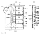
- Fig. 1 (A) is a cross-section view of the changing apparatus where the coin dispensing apparatus with a safe system of this embodiment is attached to the coin changing apparatus which is a handling apparatus.
- Fig. 1 (B) is a cross-section view of X-X line in figure 1 (A).
- Fig. 2 is an exploded perspective view of a duct of the coin handling apparatus of the embodiment.
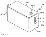
- Fig. 3 is a perspective view of the coin dispensing apparatus with a safe system of the embodiment.
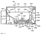
- Fig. 4 is a cross-section view on the line which passes through the center of the rotating disk of the coin dispensing apparatus with a safe system of the embodiment.
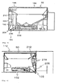
- Fig. 5 is a cross-section view of the coin dispensing slot of the coin dispensing apparatus of the embodiment.
- Fig. 6 is a cross-section view of the coin dispensing section where the coin dispensing apparatus with a safe system of this embodiment is attached to the changing apparatus.
- Fig. 7 is an outline view of the non-operating unit to the rotating disk of the coin dispensing apparatus with a safe system.
- In these embodiments, the coins are Japanese Yen, however other coins can be used, for example US dollar coins or Euro coins. In figure 1(A), the
coin handling apparatus 101 is an automatic changing machine or anATM which dispenses a predetermined domination and a predetermined quantity based on a directing signal. -
Coin dispensing apparatus 50 with safe system for 50 Yen,coin dispensing apparatus 100 with safe system for 100 Yen,coin dispensing apparatus 10 with safe system for 10 Yen andcoin dispensing apparatus 1 with safe system are located at safe areas 112,114,116 and 118 which are aligned perpendicular.
Safe areas 112,114,116 and 118 are divided by separatingplates
Coin dispensing apparatus
Coin dispensing apparatus - For example, dispensing apparatuses with a safe system which dispenses a lot in quantity are located at lower positions and those except for the above-mentioned dispensing apparatuses are located at upper positions.
Also safe type dispensing apparatuses which dispense light weight coins are located at lower positions and the dispensing apparatuses for heavier coins are located at the upper positions.
In these cases, the dispensing time for finishing all coins is as short as possible.
Coin dispensing apparatuses duct 120 which is located beside the safe area. - The dispensed coins fall in the falling
duct 120, afterwards the coins fall onto a lateraldirection transporting unit 122 which is located under theduct 120.
For example, the lateraldirection transporting unit 122 is a belt. The fallen coins are transported towards the lateral direction by the lateraldirection transporting unit 122 and are received by alifting unit 124.
Afterwards, the coins are lifted upwards by thelifting unit 124. The lateraldirection transporting unit 122 has a function which transports the fallen coins and move them away from the fallingduct 120.
Therefore, the fallen coins can be moved either obliquely upwards or obliquely downwards. - The coins lifted by the
lifting unit 124 are dispensed into a receivingslot 126 which is bowl shaped.
Dispensingslots safe areas duct 120 are located at one-side towards the right at aplate 205 for defining the fallingduct 120 as shown in figure 1(B). - Dispensed coins which are dispensed from dispensing
slots slanting guide plates slots
Afterwards, the coins fall in a fallingpassageway 150 which extends perpendicular, and go onto said lateraldirection transporting unit 122. - A second
slanting guide plate 143 which extends at a right angle to the firstslanting guide plate 142 is located below the firstslanting guide plate 142 which is located at the uppermost position.
A further secondslanting guide plate 145 which extends at a right angle to the firstslanting guide plate 144 is located below the firstslanting guide plate 144 which is located at second upper position. - First slanting guide plates 142,144,146,148 and second slanting guide plates 143,145 are a
speed reducing unit 152 for reducing the falling speed where the dispensed coins fall onto the lateral direction transporting unit.
In other words, the dispensed coins which were dispensed from each dispensing slot 132,134,136,138 are approximately level.
Accordingly, the dispensed coins have contact with the surfaces and are guided by the first slanting guide plates 142,144,146,148 and the second slanting guide plates 143,145. - Therefore, the coin speed is reduced by the friction between the guide plates and the coins.
Afterwards, the coins fall from the ends of the slanting guide plates 143,145,146,148 which are located below dispensing slots 143,134,136,138.
Accordingly, the falling speed onto the lateraldirection transporting unit 122 is reduced.
Therefore, the coin's dance bounce on the rebounding is reduced. As a result, the coins are transported quickly. - The
speed reducing unit 152 is structured where the secondslanting guide plates
The structure is desirable, because the speeds reducing effect is increased.
Also, the dispensed coins which are dispensed by thecoin dispensing apparatus slanting guide plate 147.
The coins are guided towards the side by the thirdslanting guide plate 147, and fall onto the lateraldirection transporting unit 122. - Also, the dispensed coins which are dispensed by the
coin dispensing apparatuses direction transporting unit 122 from the first slanting guide plates 146,148.
Accordingly, the falling position of the coins is dispersed.
As a result, the coins are lifted smoothly by thelifting unit 124. - Next, the structure of coin dispensing apparatuses with safe systems 50,100,10,1 which are in the present invention is explained referring to figures 3-7.
Coin dispensing apparatuses with safe systems 50,100,10,1 have principally the same structure.
Therefore, thecoin dispensing apparatus 50 which is located at the uppermost position is explained on behalf of the other apparatuses.
Coin dispensing apparatuses withsafe systems 50 includes a coin hopper with arotating disk 160, asafe cover 164 which is built in thecoin hopper 162 and anon-operating unit 166 for therotating disk 160. - Next, the
coin hopper 162 is explained.
Thecoin hopper 162 includes a coin storing bowl 170, therotating disk 160, amotor 174 and a transmitting mechanism 176.
A coin storing bowl 170 is like a cylinder and can be detached from the upper surface of abase 168.
Therotating disk 160 is located in acircle hole 172 which is located at the bottom of the bowl 170.
The motor 174 (an electric motor in this embodiment) is fixed at the upper surface of thebase 168.
The transmitting mechanism 176 transmits the rotation from themotor 174 to the rotating disk 160 (shown in figure 7). - The
motor 174 can be changed to either an air-motor, anoil-motor or etc.
An electric motor is desirable, because an electric motor is miniature and does not have an incidental equipment.
In this embodiment, the transmitting mechanism 176 is a gear transmission which includes plural gears 178.
The transmitting mechanism 176 can be changed to another transmitting mechanism which has the same function. - The bowl 170 is a cylinder which extends perpendicular, the
upper opening 180 is a rectangle and the lower opening is acircle hole 172.
Therotating disk 160 includes plural throughholes 182 which are located at a predetermined interval and receive the coins.
Also therotating disk 180 includes pushingribs 184 which are located at the reverse of therotating disk 160 which faces to thebase 168.
The lower section of therotating disk 160 is located at thecircle hole 186 which is made at the upper surface of thebase 168. - The
rotating disk 160 is fixed at arotating shaft 188.
Thegear 178 is fixed at therotating shaft 188.
Acoin outlet 190 has a notched position which is located at the circle holes 186 and 172.
The coins which fall into the throughhole 182 of therotating disk 160 are supported on the upper surface of thebase 168 and are guided by the inner surface of thecircle hole 186 and move together with therotating disk 160.
The coins are pushed out at acoin outlet 190 by the pushingrib 184, afterwards, the coins are flipped by a flipping unit (not shown). - A sensor (not shown) which detects the movement of the flipping unit outputs a counting signal for the coins.
Thecoin hopper 162 is a known hopper, for example in Japanese Laid Open Patent 2000-132723. - Next, the
safe cover 164 is explained.
Thesafe cover 164 is a box which is made by acover body 192 which is a box with a bottom and is opened at an upper opening and by alid 194 which covers the upper opening.
Thecover body 192 and thelid 194 are formed by a stainless steel plate.
Thecoin hopper 162 is built into thesafe cover 164.
In other words, thecoin hopper 162 is covered with thesafe cover 164. - The
lid 194 is a box which is opened at the bottom and can pivot on ashaft 196 at a rear wall 214 of thecover body 192 in the up and down direction.
Also thelid 194 covers the upper opening of thecover body 192 and can be locked to thecover body 192 by alocking unit 198.
Therefore, asafe cover 164 has a safe function for thecoin hopper 162.
In other words, thecoin hopper 162 which is built into thesafe cover 164 is a coin dispensing apparatus with a safe system. - A
front slanting section 200 which extends backwards and downwards is fixed at the front upper section of thecover body 192.
Arear slanting section 202 is fixed at the rear upper section. These lower sections are located in theupper opening 180 of the bowl 170.
By this, the entered coins into the upper opening of thecover body 192 are guided by slantingsections upper opening 180. - A
safe dispensing outlet 204 is located at thecover body 192 which is located face to face to thecoin outlet 190 of thecoin hopper 162.
Thecoin dispensing outlet 204 is a slot and is located at the lower edge section of afront wall 208 of thecover body 192 as shown in figure 3.
Thesafe dispensing slot 204 and thecoin dispensing slot 190 of saidcoin hopper 162 have a flat nozzle shape and are connected by aguide 206 which is fixed at the inside of thecover body 192. In other words, the flipped coins from thecoin outlet 190 are guided by theguide 206, and are dispensed in a slant situation from thesafe outlet 204. - When the
coin dispensing apparatus 50 is moved to a predetermined position at saidsafe area 112 along the separatingplate 102, thesafe dispensing outlet 204 is located near thecoin dispensing outlet 132 which is located at aplate 205 for defining the safe areas 112,114,116,118.
Anopening 210 is rectangle and is located at afront wall 208 which is located above thesafe dispensing slot 204. - A
first connector 212 for driving themotor 174 and for connecting the counting sensor is fixed at the inside of theopening 210. - In other words, the
first connector 212 is located inside thesafe cover 164, and doesn't protrude to the outer surface.
Accordingly, when thecoin dispensing apparatus 50 is carried, thefirst connector 212 doesn't protrude and doesn't get broken.
Ahandle 216 which is a ring is fixed at a rear wall 214 which is located at the opposite to thefront wall 208 of thecover body 192.
When thecoin dispensing apparatus 50 with safe system is carried, thehandle 216 is held by a person. - A
second connector 218 which is fitted to thefirst connector 212 is fixed at aplate 205 which is located at the opposite to thefront wall 208 of thesafe area 112 of thecoin handling apparatus 101.
When the coin dispensing apparatus with safe system is attached to thesafe area 112, thesecond connector 218 is fitted to thefirst connector 212.
Accordingly, the power line of themotor 174, the signal lines for the sensor and the "empty sensor" of the bowl 170 are connected automatically. - The
second connector 218 is connected to a circuit for controlling and a power circuit.
When themotor 174 isn't an electric motor; for example when the motor is an air motor, thefirst connector 212 and thesecond connector 218 can include a connector for an air pipe for providing compressed air. - Next, the
non-operating unit 166 for therotating disk 160 is explained referring to figures 4 and 7.
The first embodiment of thenon-operating unit 166 is disclosed in figure 7.
Thenon-operating unit 166 is therotation preventing unit 222 for stopping the rotation of therotating disk 160.
Therotation preventing unit 222 has a function that, when thefirst connector 212 of the coin dispensing apparatus withsafe system 50 is off from thesecond connector 218, a stopper has contact with either therotating disk 160 or the transmitting mechanism 176. In other words, therotating disk 160 can't be rotated. - The rotating preventing
unit 222 is explained referring to figure 7.
Alever 226 is pivotable on ashaft 224 which is fixed at thebase 168.
There is a stoppingtooth 228 at an end of alever 226.
The stoppingtooth 228 engages with thegear 178.
Aplunger 232 of asolenoid 230 which is fixed atbase 168 is connected with the end of thelever 226.
When theplunger 232 is pulled by the excitement of thesolenoid 230, the stoppingtooth 228 moves away from thegear 178.
Thelever 226 is urged by aspring 234 as the stoppingtooth 228 has contact with thegear 178.
In other words, when thesolenoid 230 isn't excited, the stoppingtooth 228 is engaged with thegear 178 by thespring 234.
In other words, when the power for thesolenoid 230 is stopped, the stoppingtooth 228 engages with thegear 178.
Therefore, thegear 178 can't rotate. - The
rotation preventing unit 222 can be changed to another unit which has the same function where therotating disk 160 is stopped.
For example, there is a hole which penetrates thegear 178.
When thesolenoid 230 isn't excited, a pin is inserted into the hole or the pin is inserted into the throughhole 182 of therotating disk 160. - Also, the rotation of the
motor 174 is transmitted to a worm gear, also the worm gear drives thegear 178 which is a worm wheel. In other words, the worm wheel can't be rotated by the self-lock function.
Therefore the worm wheel and the worm gear are therotation preventing unit 222.
When therotation preventing unit 222 operates, thegear 178 can't be rotated by an object which is inserted fromsafe dispensing slot 204 and thecoin outlet 190.
Accordingly, therotating disk 160 isn't rotated, and the coins which are stored in the bowl 170 aren't dispensed. - Next, a second embodiment of a
non-operating unit 166 is explained.
Thenon-operating unit 166 is ashutter 236 which closes thesafe dispensing slot 204 as shown in figure 4.
Theshutter 236 can slide along the bottom of thecover body 192 and the base 168 by means of asolenoid 238.
When thesolenoid 238 is excited, thesafe dispensing slot 204 is opened by theshutter 236 which is pulled by a plunger 240 (shown in figure 5).
When thesolenoid 238 isn't excited, thesafe dispensing slot 204 is closed by theshutter 236 which is pulled by a spring (not shown). - Therefore, when the
shutter 236 closes thesafe dispensing slot 204, an object can't be inserted into thesafe dispensing slot 204.
As a result, the coins in the bowl 170 aren't dispensed, because therotating disk 160 can't be rotated.
Also, therotation preventing unit 222 and theshutter 236 are used together or at least one of the two. - Next, the operation of this embodiment is explained. When the coin dispensing apparatuses with
safe system second connector 218 which are fixed at acoin handling apparatus 101.
Accordingly,motors 174 of coin dispensing apparatuses with safe system 50,100,10,1 are connected to the power source and the coin dispensing apparatuses 50,100,10,1 with safe system can communicate with a controlling signal.
Also, safe dispensingslots 204 are located near dispensing slots 132,134,136,138.
Afterwards,solenoids - The
lever 226 is pivoted in the counter clockwise direction shown in figure 7 by the excitement of thesolenoid 230, and the stoppingtooth 228 is away from thegear 178.
By this, thegear 178 can be rotated by themotor 174.
Also, theshutter 236 is moved to the opening position shown in figure 5 by the excitation of thesolenoid 238.
Accordingly, thesafe dispensing slot 204 is opened.
As a result, the dispensed coins which are dispensed from thecoin outlet 190 can be dispensed from thesafe dispensing slot 204. - Next, in the case where 482 Yen are dispensed is explained. In other words, the
coin dispensing apparatus 100 dispenses four coins,coin dispensing apparatus 10 dispenses three coins,coin dispensing apparatus 50 dispenses one coin andcoin dispensing apparatus 1 dispenses two coins.
The start timing of coin dispensing apparatuses which are selected are slightly staggered for prevention of a simultaneously start of the currents together.
By this, the apparatus can be made up inexpensively and can dispense the coins quickly. - For example, the
coin dispensing apparatus 100, thecoin dispensing apparatus 10, thecoin dispensing apparatus 1 and thecoin dispensing apparatus 50 are started in turn.
The sensors for counting thecoin dispensing apparatuses
When the sensors detect a predetermined coin,motors 174 of the coin dispensing apparatuses are stopped by the controlling unit. - 50 Yen coins which were dispensed from the
safe dispensing slot 204 of thecoin dispensing apparatus 50 fall into the fallingduct 120 from the dispensingslot 132, and run into the firstslanting guide plate 142 which is located under the dispensingslot 132. Afterwards, the dispensed coins slide at a right angle to the dispensing direction.
The fallen 50 Yen coins from the end offirst slanting plate 142 fall onto the secondslanting guide plate 143 which is located under thefirst slanting plate 142.
Afterwards, the coins slide to the same direction to the dispensing direction on thesecond slanting plate 143. - The fallen 50 Yen coins from the lower end of the second
slanting guide plate 143 fall in the fallingpassageway 150 which extends perpendicular, and run into the thirdslanting guide plate 147. Afterwards, the coins are turned towards the side of thesafe area 118 by the slant, and fall onto the lateraldirection transporting unit 122. - Therefore, 50 Yen coins slide on the first
slanting guide plate 142 and the secondslanting guide plate 143.
As a result, the sliding speed is reduced.
Afterwards, the coins fall from the lower section of the secondslanting guide plate 143 which is located under the dispensingslot 132, and run into the thirdslanting guide plate 147.
Afterwards, the coins fall onto the lateraldirection transporting unit 122.
Therefore, the shock when the coins run into the lateraldirection transporting unit 122, is reduced drastically.
As a result, the coin's transportation is finished quickly, because the coin's don't bounce as much. - Next, 100 Yen coins which were dispensed from the
coin dispensing apparatus 100 slide on the firstslanting guide plate 142 and the secondslanting guide plate 143 in the same way as the 50 Yen coins.
Afterwards, the coins fall in the fallingpassageway 150, and are guided to the side by the thirdslanting guide plate 147 and fall onto the lateraldirection transporting unit 122.
Therefore, the bouncing of 100 Yen coins comes to a rest quickly similar to the above-mentioned. - Next, 10 Yen coins which were dispensed from the
coin dispensing apparatus 10 slide on the firstslanting guide plate 142.
Afterwards, the coins fall in the fallingpassageway 150, and fall onto the lateraldirection transporting unit 122.
Therefore, the height of the end of thefirst slanting guide 142 from the lateraldirection transporting unit 122 is low.
As a result, the bounce of 10 Yen coins comes to a rest quickly. - Next, 1 Yen coins which were dispensed from the
coin dispensing apparatus 1 slide on the firstslanting guide plate 142 similar to the 10 Yen coins.
Afterwards, the coins fall in the fallingpassageway 150, and fall onto the lateraldirection transporting unit 122.
Therefore, the height of the end of thefirst slanting guide 142 from the lateraldirection transporting unit 122 is low.
As a result, the bounce of 10 Yen coins comes to a rest quickly. - When the transporting distance of the lateral
direction transporting unit 122 is short, the coin's bouncing comes to a rest quickly, before that the coins arrive to thelifting unit 124.
Therefore, the coins are lifted by thelifting unit 124.
In other words, the coin's dispensing time is reduced and the coin handling apparatus is miniature. - When the coin dispensing apparatuses 50,100,10,1 are detached from safe areas 112,114,116,118, the
first connectors 212 are released from thesecond connectors 218.
Therefore, thesolenoids
By this, thelever 226 is pivoted in the clockwise direction by thespring 234.
Accordingly, the stoppingtooth 228 is engaged with thegear 178.
Thegear 178 can't be rotated.
As a result, therotating disk 160 isn't rotated. - Also, when the
solenoid 238 isn't excited, theshutter 236 closes thesafe dispensing slot 204.
Therefore, an object can't be inserted into thesafe dispensing slot 204, therotating disk 160 isn't rotated.
In other words, the coins cannot be taken illegally from the coin dispensing apparatuses 50,100,10,1. - This present invention can be used to an automatic charging apparatus, an coin dispensing apparatus of an automatic exchanging apparatus or etc.
Claims (3)
- A coin dispensing apparatus with a safe system comprising :a coin dispensing apparatus (1,10,50,100) which includes a rotating disk (160) with through holes (182) which is located at the bottom of a coin storing bowl (170) with an upper opening (180) and which is rotated by an electric motor (174) through a transfer mechanism (176);a safe cover (164) which is built in said coin dispensing apparatus, which can be detached from a coin handling apparatus (101), and includes a dispensing slot (204) for dispensing dispensed coins from said coin dispensing apparatus; characterised in that it further comprisesa non-operating unit (166) for said coin dispensing apparatus, when said safe cover is detached from said coin handling apparatus,wherein
said non-operating unit (166) comprises a stopping tooth (228) which is engageable with said transfer mechanism. - The coin dispersing apparatus with a safe system as claimed in claim 1, wherein
said non-operating unit (166) comprises a shutter (236) which is adapted to shut a dispensing slot (204) for coins. - The coin dispensing apparatus with safe system as claimed in any of claims 1 to 2, wherein
an opening (210) of a connector (212) for operating said motor (174) is located at the front surface of said safe cover (164) to said coin handling apparatus (101).
Applications Claiming Priority (2)
| Application Number | Priority Date | Filing Date | Title |
|---|---|---|---|
| JP2004077433A JP4474583B2 (en) | 2004-03-18 | 2004-03-18 | Safe coin dispenser |
| JP2004077433 | 2004-03-18 |
Publications (2)
| Publication Number | Publication Date |
|---|---|
| EP1577845A1 EP1577845A1 (en) | 2005-09-21 |
| EP1577845B1 true EP1577845B1 (en) | 2007-05-02 |
Family
ID=34836565
Family Applications (1)
| Application Number | Title | Priority Date | Filing Date |
|---|---|---|---|
| EP05001192A Ceased EP1577845B1 (en) | 2004-03-18 | 2005-01-21 | Coin dispensing apparatus with safe system |
Country Status (4)
| Country | Link |
|---|---|
| US (1) | US7186176B2 (en) |
| EP (1) | EP1577845B1 (en) |
| JP (1) | JP4474583B2 (en) |
| DE (1) | DE602005001008T2 (en) |
Families Citing this family (14)
| Publication number | Priority date | Publication date | Assignee | Title |
|---|---|---|---|---|
| US7080755B2 (en) | 2004-09-13 | 2006-07-25 | Michael Handfield | Smart tray for dispensing medicaments |
| DE602006012392D1 (en) * | 2005-04-28 | 2010-04-08 | Asahi Seiko Co Ltd | Coin dispensing method for a coin dispenser, coin dispenser and coin recycling machine with the coin dispenser |
| BRPI0613874A2 (en) * | 2005-07-27 | 2011-02-15 | Mei Inc | banknote cassette and the like |
| JP4671806B2 (en) * | 2005-08-24 | 2011-04-20 | 日立オムロンターミナルソリューションズ株式会社 | Coin processing equipment |
| DE202007011913U1 (en) * | 2007-08-24 | 2008-02-28 | Jüngst, Fritz | Hopper arrangement |
| US8135497B2 (en) * | 2010-01-13 | 2012-03-13 | Joslyn Matthew I | Portable, personal medication dispensing apparatus and method |
| US8616942B2 (en) * | 2010-04-22 | 2013-12-31 | Telequip Corporation | Modular bulk coin dispenser with hopper removal from drive and control mechanism |
| US11246800B2 (en) * | 2012-10-05 | 2022-02-15 | Alixa Rx, Llc | Locking canister for dispensing medications |
| GB201300462D0 (en) * | 2013-01-11 | 2013-02-27 | Asahi Seiko Europ Ltd | Disk sorting device |
| DE102015101423A1 (en) * | 2015-01-30 | 2016-08-04 | Crane Payment Solutions Gmbh | Device for dispensing coins |
| DE102015101421B3 (en) * | 2015-01-30 | 2016-07-28 | Crane Payment Solutions Gmbh | Device for dispensing coins |
| JP6402332B2 (en) * | 2015-09-09 | 2018-10-10 | 旭精工株式会社 | Coin hopper |
| US10940092B2 (en) * | 2017-04-19 | 2021-03-09 | Michael Moonsup Song | Technologies for medicine dispensing |
| IT201900006563A1 (en) * | 2019-05-06 | 2020-11-06 | Cometa S P A | Safety unit for the transport of coin rolls for a coin roll dispensing machine |
Family Cites Families (11)
| Publication number | Priority date | Publication date | Assignee | Title |
|---|---|---|---|---|
| BR7404269D0 (en) * | 1973-05-25 | 1975-01-07 | Glory Kogyo Kk | IMPROVEMENTS IN OR RELATING TO COINS PACKAGING MACHINES |
| US3926366A (en) * | 1974-03-01 | 1975-12-16 | August M Sciortino | Pilfer-proof locking cover for a coin box |
| US4921463A (en) * | 1987-10-27 | 1990-05-01 | Cummins-Allison Corporation | Coin sorter with counter and brake mechanism |
| JP2514825B2 (en) | 1987-10-31 | 1996-07-10 | 日本電気ホームエレクトロニクス株式会社 | Safe device |
| US5046989A (en) * | 1988-08-18 | 1991-09-10 | Jack Dass | Coin storage and dispensing apparatus |
| US5667096A (en) * | 1995-07-18 | 1997-09-16 | Wu; King-Sheng | Drug storing apparatus for automatic drug dispensing machines |
| JP3276847B2 (en) * | 1996-05-31 | 2002-04-22 | 株式会社湯山製作所 | Pill feeder |
| JPH11250301A (en) | 1998-03-02 | 1999-09-17 | Asahi Seiko Co Ltd | Mechanism for mounting hopper device |
| US6193599B1 (en) * | 1998-10-20 | 2001-02-27 | Asahi Seiko Co., Ltd. | Coin hopper device |
| GB9912696D0 (en) * | 1999-06-02 | 1999-08-04 | Ncr Int Inc | Coin dispenser |
| JP4258753B2 (en) * | 2001-06-13 | 2009-04-30 | 旭精工株式会社 | Hopper with shutter |
-
2004
- 2004-03-18 JP JP2004077433A patent/JP4474583B2/en not_active Expired - Lifetime
-
2005
- 2005-01-21 EP EP05001192A patent/EP1577845B1/en not_active Ceased
- 2005-01-21 DE DE602005001008T patent/DE602005001008T2/en active Active
- 2005-03-09 US US11/075,591 patent/US7186176B2/en not_active Expired - Fee Related
Also Published As
| Publication number | Publication date |
|---|---|
| US20050236254A1 (en) | 2005-10-27 |
| DE602005001008T2 (en) | 2007-08-23 |
| US7186176B2 (en) | 2007-03-06 |
| JP4474583B2 (en) | 2010-06-09 |
| EP1577845A1 (en) | 2005-09-21 |
| DE602005001008D1 (en) | 2007-06-14 |
| JP2005267133A (en) | 2005-09-29 |
Similar Documents
| Publication | Publication Date | Title |
|---|---|---|
| EP1577845B1 (en) | Coin dispensing apparatus with safe system | |
| US8844704B2 (en) | Money item dispensing apparatus | |
| JP4340591B2 (en) | Collective insertion mechanism of game medals for inter-machines | |
| WO2004023404A1 (en) | Coin changing machine | |
| JP3679017B2 (en) | Coin change machine | |
| JP4340590B2 (en) | Collective insertion mechanism of game medals for inter-machines | |
| JP4295681B2 (en) | Collective insertion mechanism of game medals for inter-machines | |
| JP4222971B2 (en) | Slot machines, gaming machines, medal lending machines and gaming media lending machines | |
| JP4340587B2 (en) | Collecting mechanism for game medals | |
| JP2007181595A (en) | Inter-game machine for game machine | |
| JP2007236577A (en) | System for collectively loading game tokens | |
| JP3766130B2 (en) | Coin dispenser | |
| JP4579176B2 (en) | Medal feeder | |
| JP2006000370A (en) | Mechanism for collectively feeding game token for device between game machines | |
| JP7088722B2 (en) | Coin processing equipment | |
| JP4444899B2 (en) | Pedestrian machine for gaming machines | |
| JP4527620B2 (en) | Medal feeder | |
| JP4608447B2 (en) | Pedestrian machine for gaming machines | |
| JP2005270623A (en) | Game medium lifting mechanism | |
| JP2003190616A (en) | Medal dispenser | |
| JP2007089979A (en) | Game machine | |
| JP2006000407A5 (en) | ||
| JP2006340934A (en) | Token feeding device | |
| JP2006346146A (en) | Token feeder | |
| JPH08329299A (en) | Coin payout device |
Legal Events
| Date | Code | Title | Description |
|---|---|---|---|
| PUAI | Public reference made under article 153(3) epc to a published international application that has entered the european phase |
Free format text: ORIGINAL CODE: 0009012 |
|
| AK | Designated contracting states |
Kind code of ref document: A1 Designated state(s): AT BE BG CH CY CZ DE DK EE ES FI FR GB GR HU IE IS IT LI LT LU MC NL PL PT RO SE SI SK TR |
|
| AX | Request for extension of the european patent |
Extension state: AL BA HR LV MK YU |
|
| 17P | Request for examination filed |
Effective date: 20050805 |
|
| AKX | Designation fees paid |
Designated state(s): DE GB |
|
| GRAP | Despatch of communication of intention to grant a patent |
Free format text: ORIGINAL CODE: EPIDOSNIGR1 |
|
| GRAS | Grant fee paid |
Free format text: ORIGINAL CODE: EPIDOSNIGR3 |
|
| GRAA | (expected) grant |
Free format text: ORIGINAL CODE: 0009210 |
|
| AK | Designated contracting states |
Kind code of ref document: B1 Designated state(s): DE GB |
|
| REG | Reference to a national code |
Ref country code: GB Ref legal event code: FG4D |
|
| REF | Corresponds to: |
Ref document number: 602005001008 Country of ref document: DE Date of ref document: 20070614 Kind code of ref document: P |
|
| PLBE | No opposition filed within time limit |
Free format text: ORIGINAL CODE: 0009261 |
|
| STAA | Information on the status of an ep patent application or granted ep patent |
Free format text: STATUS: NO OPPOSITION FILED WITHIN TIME LIMIT |
|
| 26N | No opposition filed |
Effective date: 20080205 |
|
| PGFP | Annual fee paid to national office [announced via postgrant information from national office to epo] |
Ref country code: DE Payment date: 20210105 Year of fee payment: 17 Ref country code: GB Payment date: 20210113 Year of fee payment: 17 |
|
| REG | Reference to a national code |
Ref country code: DE Ref legal event code: R119 Ref document number: 602005001008 Country of ref document: DE |
|
| GBPC | Gb: european patent ceased through non-payment of renewal fee |
Effective date: 20220121 |
|
| PG25 | Lapsed in a contracting state [announced via postgrant information from national office to epo] |
Ref country code: GB Free format text: LAPSE BECAUSE OF NON-PAYMENT OF DUE FEES Effective date: 20220121 Ref country code: DE Free format text: LAPSE BECAUSE OF NON-PAYMENT OF DUE FEES Effective date: 20220802 |