EP1577720A2 - Procédé et dispositif pour réduire les erreurs dues à une asymétrie de ligne dans des dispositifs qui utilisent le piégeage cohérent de population (CPT) - Google Patents
Procédé et dispositif pour réduire les erreurs dues à une asymétrie de ligne dans des dispositifs qui utilisent le piégeage cohérent de population (CPT) Download PDFInfo
- Publication number
- EP1577720A2 EP1577720A2 EP04025646A EP04025646A EP1577720A2 EP 1577720 A2 EP1577720 A2 EP 1577720A2 EP 04025646 A EP04025646 A EP 04025646A EP 04025646 A EP04025646 A EP 04025646A EP 1577720 A2 EP1577720 A2 EP 1577720A2
- Authority
- EP
- European Patent Office
- Prior art keywords
- frequency
- cpt
- electromagnetic radiation
- generating
- asymmetry
- Prior art date
- Legal status (The legal status is an assumption and is not a legal conclusion. Google has not performed a legal analysis and makes no representation as to the accuracy of the status listed.)
- Withdrawn
Links
Images


Classifications
-
- H—ELECTRICITY
- H03—ELECTRONIC CIRCUITRY
- H03L—AUTOMATIC CONTROL, STARTING, SYNCHRONISATION OR STABILISATION OF GENERATORS OF ELECTRONIC OSCILLATIONS OR PULSES
- H03L7/00—Automatic control of frequency or phase; Synchronisation
- H03L7/26—Automatic control of frequency or phase; Synchronisation using energy levels of molecules, atoms, or subatomic particles as a frequency reference
-
- G—PHYSICS
- G04—HOROLOGY
- G04F—TIME-INTERVAL MEASURING
- G04F5/00—Apparatus for producing preselected time intervals for use as timing standards
- G04F5/14—Apparatus for producing preselected time intervals for use as timing standards using atomic clocks
-
- G—PHYSICS
- G04—HOROLOGY
- G04F—TIME-INTERVAL MEASURING
- G04F5/00—Apparatus for producing preselected time intervals for use as timing standards
- G04F5/14—Apparatus for producing preselected time intervals for use as timing standards using atomic clocks
- G04F5/145—Apparatus for producing preselected time intervals for use as timing standards using atomic clocks using Coherent Population Trapping
Definitions
- CPT Coherent-Population-Trapping
- US patents 6,363,091 and 6,201,821 which are hereby incorporated by reference. Since such frequency standards are known to the art, they will not be described in detail here.
- ⁇ L is the average frequency of the CPT-generating components.
- the average vacuum wavelength of the electromagnetic source is approximately c/ ⁇ L , where c is the speed of light in a vacuum.
- the quantum absorber has two low energy states (which shall be referred to as state A and state B), and n high energy states, each of which can be reached by a transition from state A and by a transition from state B.
- the high energy states by C k , for 1 ⁇ k ⁇ n.
- the quantum absorber may have any number of other low energy states and high energy states.
- the mean energy of state B, E B is taken to be greater than or equal to the mean energy of state A, E A .
- ⁇ 0 (E B -E A )/ h , where h is Planck's constant.
- the quantum absorber can exhibit the phenomenon called Coherent-Population-Trapping (CPT), assuming that the value of ⁇ L falls in the necessary range so that the CPT-generating frequency component with frequency ⁇ L + 1 ⁇ 2 ⁇ induces transitions between the state A and the states C k , and the CPT-generating frequency component with frequency ⁇ L - 1 ⁇ 2 ⁇ induces transitions between the state B and the states C k .
- CPT Coherent-Population-Trapping
- the quantum absorber When ⁇ and ⁇ 0 are exactly equal, for fixed ⁇ L , the quantum absorber exhibits an absorption (and fluorescence) minimum, and a transmission maximum, of the CPT-generating components.
- One class of frequency standards utilizes the CPT phenomenon to adjust a frequency source such that its output frequency is equal to some function of ⁇ 0 by maintaining the frequency ⁇ at the value that maximizes the transmission (or minimizes fluorescence) of the quantum absorber. If ⁇ 0 remains constant, then the frequency source can be used as a frequency standard having high accuracy, as long as a reliable method exists for determining ⁇ 0 .
- each source that causes ⁇ 0 to vary must be carefully controlled, or else means must be applied to the quantum absorber to reduce the sensitivity of ⁇ 0 to that source. For example, if the quantum absorber is 87 Rb vapor in a cell with a buffer gas and a magnetic field, then some of the sources that cause ⁇ 0 to vary are fluctuations in the strength of the applied magnetic field, and the buffer gas pressure. Hence, reliable operation of the standard must ensure the constancy of the magnetic field and the buffer gas pressure.
- the transmitted power, T( ⁇ L , ⁇ ) will be a function of both ⁇ L and ⁇ .
- Prior art methods determine the value of ⁇ that maximizes the transmission by utilizing an algorithm that assumes that the transmission curve is a symmetric function of ⁇ about ⁇ 0 for fixed ⁇ L when ⁇ is near to ⁇ 0 . If the transmission curve does not satisfy this symmetry condition, the determination of ⁇ 0 will be in error.
- T( ⁇ L , ⁇ ) is often not a symmetric function of ⁇ about ⁇ 0 for fixed ⁇ L .
- the Rabi frequency associated with the transition between state A and state C k by ⁇ Ak and the Rabi frequency associated with the transition between state B and state C k by ⁇ Bk .
- the transmission curve T( ⁇ L , ⁇ ), with ⁇ L held fixed, is a symmetric function of ⁇ about ⁇ 0 only when, for each high energy state C k ,
- 2
- T( ⁇ L , ⁇ ), for ⁇ L held fixed will not normally be a symmetric function of ⁇ about ⁇ 0 , and an error will be made in the determination of the value of ⁇ that maximizes the transmission through the quantum absorber.
- the present invention is an apparatus and method for measuring CPT.
- the apparatus includes a quantum absorber that is irradiated by radiation from an electromagnetic radiation source.
- the quantum absorber includes a material having first and second low energy states coupled to a common high energy state. Transitions between the first low energy state and the common high energy state or between the second low energy state are induced by electromagnetic radiation.
- the electromagnetic radiation source generates electromagnetic radiation having first and second CPT-generating frequency components.
- the first CPT-generating frequency component has a frequency ⁇ L - ⁇ , and a first CPT component amplitude.
- the second CPT generating frequency component has a frequency ⁇ L + ⁇ and a second CPT component amplitude.
- the apparatus also includes a detector for generating a detector signal related to the power of electromagnetic radiation that leaves the quantum absorber.
- the detector signal exhibits an asymmetry as a function of frequency in a frequency range about a frequency ⁇ 0 .
- the apparatus includes a CPT servo loop that alters ⁇ in response to the detector signal and an asymmetry servo loop that alters one of ⁇ L , the first CPT component amplitude, and the second CPT component amplitude in a manner that reduces the asymmetry.
- the apparatus includes an EM (ElectroMagnetic) frequency control circuit that determines ⁇ L .
- the EM control circuit is responsive to an EM frequency control signal.
- the asymmetry servo loop alters the EM frequency control signal.
- the asymmetry servo loop alters one or both of the first CPT component amplitude and the second CPT component amplitude.
- the electromagnetic radiation source further generates additional frequency components for altering an AC Stark shift in the quantum absorber, the additional frequency components having amplitudes that are determined by an AC Stark shift control signal.
- This embodiment includes an AC Stark shift servo loop that generates the Stark shift control signal.
- the electromagnetic radiation source includes a source for generating electromagnetic radiation having a frequency ⁇ L in response to a first control signal and a modulator for modulating the generated electromagnetic radiation at a frequency ⁇ in response to a second control signal.
- the EM radiation source includes a laser.
- the CPT-generating frequency components are produced by modulating a laser and utilizing two of the side bands as the CPT-generating components.
- Systems that generate the CPT-generating components by other methods will be discussed in more detail below.
- the present invention is based on the observation that the asymmetry in the transmission curve can be reduced by utilizing a servo loop to adjust the laser frequency or the laser modulation parameters.
- the Rabi frequencies ⁇ Ak and ⁇ Bk for the appropriate values of k can be altered by altering the ratio of the amplitudes of the CPT-generating frequency components in the input light in a manner that reduces the asymmetry in the transmission curve.
- the center frequency of the laser can be offset to reduce the asymmetry of the transmission curve.
- a combination of both servo loops can be utilized.
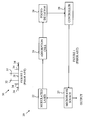
- FIG. 1 is a block diagram of a prior art CPT-based reference signal generator 20.
- Reference signal generator 20 utilizes a laser 22 that is modulated at a frequency determined by a microwave source 27.
- the modulation frequency will be denoted by ⁇ in the following discussion.
- the frequency of the laser will be denoted by ⁇ L .
- ⁇ L is also the average of the CPT-generating frequencies in this case.
- laser modulation is well known in the art, a single block 22 representing the modulated laser is shown in Figure 1. It must be emphasized that the electromagnetic source need not be a modulated laser. The present discussion will use a modulated laser to merely simplify the discussion.
- the optical spectrum generated by the modulated laser is shown at 30 in Figure 2.
- Absorption cell 24 in Figure 1 contains a quantum absorber having two ground states, state A and state B, that are separated by an energy difference corresponding to a frequency difference ⁇ 0 , and n excited states, each of which can be connected by separate electromagnetic fields to one or both ground states.
- One such energy level scheme is shown in Figure 5.
- One CPT-generating frequency component induces transitions between state A and one of the excited states as shown at 161 and the other CPT-generating frequency component, induces transitions between state B and that same excited state as shown at 162.
- the absorption cell has a minimum in its absorption when the frequency difference of the CPT-generating frequency components 32 and 33, i.e., 2 ⁇ , is equal to ⁇ 0 provided the laser frequency, ⁇ L , is properly set.
- the intensity of electromagnetic radiation leaving the quantum absorber is sensed by photodetector 28 and controller 29, which sets the value of ⁇ to maximize the transmission of cell 24.
- the frequency of microwave source 27 will be equal to a frequency ⁇ 0 .
- the CPT-generating frequency components are the first order sidebands of the modulated laser signal.
- any two frequency components in the modulated light signal can be utilized at the CPT-generatin,g frequency components provided the servo loop can adjust the frequency difference between the two frequency components.
- ⁇ 0 will be used for the modulation frequency at which the transmission of the CPT-generating frequency components is maximized for the particular choice of frequency components being used.
- 2
- 2 , then T 1 ( ⁇ ) is a symmetric function about ⁇ 0 , i.e., T 1 ( ⁇ ) T 1 (2 ⁇ 0 - ⁇ ).
- T 1 ( ⁇ ) T 1 (2 ⁇ 0 - ⁇ ).
- Figure 3 illustrates a transmission function 50.
- the present invention reduces this error either by adjusting the absolute amplitude of each CPT-generating frequency component, or by adjusting the laser frequency ⁇ L , in a manner that reduces the asymmetry of the transmission curve even when
- Embodiments that utilize a combination of these two methods can also be constructed.
- the present invention uses a servo loop that generates an error signal that is related to some measure of asymmetry in the transmission curve of the quantum absorber as a function of the microwave frequency.
- a servo loop that generates an error signal that is related to some measure of asymmetry in the transmission curve of the quantum absorber as a function of the microwave frequency.
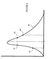
- Figure 6 illustrates an asymmetric transmission curve 60.
- a microwave frequency servo loop has already adjusted ⁇ such that points 61 and 62 have the same transmission for some predetermined value of ⁇ .
- the asymmetry error detector measures the transmission at two other points, 63 and 64 that correspond to microwave frequencies of ⁇ '.
- the error signal is T( ⁇ + ⁇ ')-T( ⁇ - ⁇ '); however, any other suitable function of the difference in transmission at the two points can be utilized.
- the above-described asymmetry detector assumes that the microwave frequency has been adjusted in a separate servo loop. That servo loop utilizes an error signal related to the difference in transmissions at points 61 and 62, i.e., T( ⁇ + ⁇ )-T( ⁇ - ⁇ ), to set the value of v.
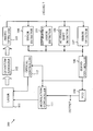
- FIG 7 is a block diagram of a frequency standard 100 according to one embodiment of the present invention.
- the quantum absorber 102 is irradiated with light from a laser 101.
- other forms of electromagnetic radiation can be utilized as discussed below.
- the power of the light leaving quantum absorber 102 is measured by a photodetector 103 that generates an output signal that is used by various error detectors and servo loops.
- Frequency standard 100 controls the amplitude and frequency of the microwave source that modulates the output of laser 101 via modulation controller 111 that controls the modulation amplitude as discussed above.
- the frequency of the microwaves is set by voltage-controlled oscillator (VCO) 109 in response to control signals from servo controller 108.
- VCO voltage-controlled oscillator
- the frequency and amplitude of the laser output signal are controlled by optical controller 112 in response to signals from servo controller 108.
- Frequency standard 100 utilizes four servo loops to stabilize the frequency of the output signal.
- the first loop sets ⁇ by changing the output frequency of VCO 109 until points 61 and 62 shown in Figure 6 are equal.
- the second and third loops set ⁇ L .
- ⁇ L is set by a single servo loop 104 that adjusts ⁇ L such that the transmission curve as a function of ⁇ L has a minimum.
- the servo controller causes the laser frequency to be switched back and forth between ⁇ L + ⁇ L and ⁇ L - ⁇ L .
- the transmission curve is measured at each of these frequencies and an error signal related to the difference in transmission is used to servo ⁇ L .
- this assures that the laser frequency is set at the point between the transition frequencies to and from states A and B and the common high energy state discussed above.
- the present invention is based on the observation that the symmetry of the transmission curve as a function of ⁇ can be altered by slightly detuning the laser frequency from this value.
- the amount of the detuning is determined by asymmetry error detector 105, which generates an error signal related to the difference in transmission that occurs when the microwave source is switched back and forth between ⁇ + ⁇ ' and ⁇ - ⁇ ' as discussed above.
- the asymmetry error signal is used to offset the laser frequency error signal generated by the laser frequency error detector 104 to provide the error signal used to servo the laser frequency.
- the fourth servo loop adjusts the amplitude of the microwave modulation signal to reduce errors resulting from the AC Stark Shift.
- the value of ⁇ obtained by the above described three servos depends, in general, on the intensity of the light from laser 101. Hence, fluctuations in the laser intensity lead to fluctuations in the value of v.
- One method for reducing the AC Stark shift operates by introducing additional frequency components (AC-Stark-shift-manipulating frequency components) into the applied electromagnetic field. If the AC-Stark-shift-manipulating frequency components have the correct amplitudes and frequencies relative to the amplitudes of the CPT-generating frequency components discussed above, the AC Stark shift is substantially reduced. In this case, the difference in energy between the two low states utilized for the CPT effect will be insensitive to variations in the total light intensity.
- a phase or frequency modulated laser is used to generate the CPT-generating frequency components, all of the non-CPT generating components act as AC Stark-shift manipulating frequency components.
- the relative intensities of the AC-Stark-shift-manipulating frequency components are controlled by adjusting the amplitude of the microwave signal applied to modulate the laser.
- the modulation amplitude can be adjusted with a servo loop that utilizes an error signal obtained by switching the laser intensity back and forth between two slightly different intensities and measuring the difference in ⁇ obtained at each of these intensities. The difference in the measured value of ⁇ is then used to generate an error signal that is used by servo controller 108 to adjust the amplitude of the modulation signal that is applied to laser 101.
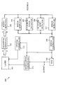
- FIG 8 is a block diagram of an embodiment of a frequency standard 200 according to another embodiment of the present invention.
- those elements of frequency standard 200 that operate in a manner analogous to elements discussed above with reference to Figure 7 have been given the same numeric designations and will not be discussed in detail here.
- Frequency standard 200 alters the amplitudes of the two CPT-generating components to reduce the asymmetry in the transmission function discussed above.
- the relative amplitudes of the CPT-generating components can be altered by modulating both the amplitude and phase of the laser output.
- the relative amplitudes of the CPT-generating components can be altered by adjusting the depth and/or phase of the amplitude modulation relative to those for the phase modulation.
- the depth of the phase modulation is also used to alter the ratios of the CPT-generating components and the other side bands that are utilized to reduce.errors due to the AC Stark Shift discussed above.
- modulation controller 211 has inputs for controlling the modulation of both the phase and amplitude of the laser.
- the error signal generated by asymmetry error detector 205 is used by servo controller 208 to servo the amplitude modulation, and the error signal generated by AC Stark Shift detector 206 is used to servo the phase modulation.
- the degree of correction obtained in the second embodiment is, in principle, greater than that obtained by detuning the laser frequency.
- the dynamic range available in the phase or amplitude modulations may not be sufficient to completely equalize the Rabi frequencies in some cases.
- the two strategies can be combined by using the detuning of the laser frequency to reduce the asymmetry to a level that is within the range of the Rabi frequency equalization mechanism.
- a modulated laser as the source of electromagnetic radiation to induce CPT in the quantum absorber.
- suitable electromagnetic radiation sources can be utilized.
- a light source can be constructed by phase locking two lasers that differ in frequency by an amount that can be controlled by a servo.
- teachings of the present invention can be applied to electromagnetic radiation sources that are outside the optical range.
- the frequency at which the EM source is modulated can be outside the microwave range. Such a case will occur for quantum absorbers in which the low-energy states are separated by frequencies outside of the microwave range.
- the CPT-generating frequency components were two side bands in the modulated laser spectrum.
- any two frequency components in the spectrum can be utilized.
- ⁇ L is the average of the two CPT-generating components, and the detuning servo is applied to the controller that determines this average.
- the detuning servo sets the average frequency of the two lasers. For example, the frequency of one of the lasers can be altered, and the phase-locking circuitry will then move the other laser's frequency to a frequency that maintains the difference in frequency specified by the servo that sets ⁇ ,
- the above embodiments of the present invention have been directed to frequency standards in which the goal is to produce a standard signal whose frequency is relatively insensitive to variations in environmental conditions.
- the present invention can also be utilized to construct a sensor that measures some physical quantity such as magnetic field strength.
- a quantum absorber in which the CPT is based on two low energy states having an energy difference that depends on an external magnetic field that is applied to the quantum absorber. By measuring the modulation frequency at which the CPT is maximized, the strength of the external magnetic field can be deduced.
- a magnetic field strength measuring apparatus can be constructed using transitions between states of 87 Rb.
- the energy levels in the ground states of 87 Rb shift in response to an external magnetic field that is applied to the atom. If two ground states are chosen in which the energy difference of the ground states is a function of the applied magnetic field, the frequency of the output signal, which is determined by the frequency difference between the two CPT-generating frequency components, can be used to measure the magnetic field.
- Similar sensors can be constructed to measure electric field strength or other environmental variables by choosing the suitable energy states in a suitable quantum absorber for CPT generation.
- the quantum absorber discussed above can be any material that exhibits the CPT effect.
- alkali metals such as lithium, sodium, potassium, rubidium, and cesium can also be utilized.
- suitable ions, molecules, or doped solid materials can be utilized.
- ions that are isotopes of Be + , Mg + , Ca + , Sr + , Ba + , Zn + , Cd + , Hg + , and Yb + can be utilized.
Landscapes
- Physics & Mathematics (AREA)
- General Physics & Mathematics (AREA)
- Spectroscopy & Molecular Physics (AREA)
- Life Sciences & Earth Sciences (AREA)
- Ecology (AREA)
- Semiconductor Lasers (AREA)
- Investigating Or Analysing Materials By Optical Means (AREA)
- Electronic Switches (AREA)
- Analysing Materials By The Use Of Radiation (AREA)
Applications Claiming Priority (2)
| Application Number | Priority Date | Filing Date | Title |
|---|---|---|---|
| US10/805,005 US7345553B2 (en) | 2004-03-18 | 2004-03-18 | Method and apparatus for reducing errors due to line asymmetry in devices utilizing coherent population trapping |
| US805005 | 2004-03-18 |
Publications (2)
| Publication Number | Publication Date |
|---|---|
| EP1577720A2 true EP1577720A2 (fr) | 2005-09-21 |
| EP1577720A3 EP1577720A3 (fr) | 2005-11-30 |
Family
ID=34838953
Family Applications (1)
| Application Number | Title | Priority Date | Filing Date |
|---|---|---|---|
| EP04025646A Withdrawn EP1577720A3 (fr) | 2004-03-18 | 2004-10-28 | Procédé et dispositif pour réduire les erreurs dues à une asymétrie de ligne dans des dispositifs qui utilisent le piégeage cohérent de population (CPT) |
Country Status (3)
| Country | Link |
|---|---|
| US (1) | US7345553B2 (fr) |
| EP (1) | EP1577720A3 (fr) |
| JP (1) | JP2005265836A (fr) |
Cited By (4)
| Publication number | Priority date | Publication date | Assignee | Title |
|---|---|---|---|---|
| RU2466485C1 (ru) * | 2011-05-24 | 2012-11-10 | Открытое акционерное общество "Российский институт радионавигации и времени" | Рубидиевая ячейка поглощения |
| EP2891247A4 (fr) * | 2012-08-30 | 2015-10-28 | Ricoh Co Ltd | Oscillateur atomique et procédé d'interrogation à résonance de piégeage cohérent de population |
| CN106370621A (zh) * | 2016-08-16 | 2017-02-01 | 苏州瑞蓝环保科技有限公司 | 基于倍频半导体激光的气态元素汞浓度检测装置及方法 |
| CN109856570A (zh) * | 2019-02-28 | 2019-06-07 | 中国计量大学 | 一种相干布居囚禁cpt铷原子磁力仪 |
Families Citing this family (17)
| Publication number | Priority date | Publication date | Assignee | Title |
|---|---|---|---|---|
| US7202751B2 (en) * | 2004-10-18 | 2007-04-10 | Agilent Inc. | Optically pumped frequency standard with reduces AC stark shift |
| US20090296760A1 (en) * | 2008-05-27 | 2009-12-03 | Miao Zhu | Optical Pumping Apparatus and Method to Reduce AC Stark Shift in Atomic Frequency Standards |
| US8237514B2 (en) | 2009-02-06 | 2012-08-07 | Seiko Epson Corporation | Quantum interference device, atomic oscillator, and magnetic sensor |
| JP5381400B2 (ja) * | 2009-02-06 | 2014-01-08 | セイコーエプソン株式会社 | 量子干渉装置、原子発振器、および磁気センサー |
| JP5540619B2 (ja) * | 2009-09-16 | 2014-07-02 | セイコーエプソン株式会社 | 原子発振器の制御方法 |
| CN102291134B (zh) * | 2011-06-02 | 2013-03-27 | 江汉大学 | 一种用于原子频标的环路响应时间测量装置及方法 |
| JP5818000B2 (ja) * | 2011-12-09 | 2015-11-18 | セイコーエプソン株式会社 | 原子発振器、原子発振器の制御方法及び量子干渉装置 |
| US9325334B2 (en) * | 2013-06-12 | 2016-04-26 | Texas Instruments Incorporated | IC, process, device generating frequency reference from RF gas absorption |
| JP2014007760A (ja) * | 2013-09-09 | 2014-01-16 | Seiko Epson Corp | 原子発振器 |
| US10171095B2 (en) | 2013-09-27 | 2019-01-01 | Seiko Epson Corporation | Atomic oscillator, electronic apparatus, moving object, and manufacturing method of atomic oscillator |
| CN104363017B (zh) * | 2014-10-09 | 2017-08-25 | 兰州空间技术物理研究所 | 提高原子频标查询信号信噪比的方波矢量锁定放大方法 |
| CN104410414B (zh) * | 2014-11-26 | 2017-09-01 | 江汉大学 | 基于弛豫时间的信号控制装置和方法 |
| CN104503077B (zh) * | 2014-12-24 | 2016-07-27 | 中国科学院上海高等研究院 | 一种实现量子相干的光电混合系统 |
| CN111044954B (zh) * | 2019-12-19 | 2022-04-12 | 北京航天控制仪器研究所 | 一种多峰闭环无方向盲区cpt磁力测量方法 |
| CN112782106B (zh) * | 2020-12-23 | 2021-11-30 | 山西大学 | 一种获得窄线宽里德堡原子光谱的装置和方法 |
| JP7797917B2 (ja) * | 2022-02-28 | 2026-01-14 | 日本電気株式会社 | 原子発振器 |
| US12038465B2 (en) * | 2022-03-11 | 2024-07-16 | The Mitre Corporation | Self-locked Rydberg atom electric field sensor |
Family Cites Families (5)
| Publication number | Priority date | Publication date | Assignee | Title |
|---|---|---|---|---|
| US6320472B1 (en) * | 1999-01-26 | 2001-11-20 | Kernco, Inc. | Atomic frequency standard |
| IT1307355B1 (it) | 1999-10-05 | 2001-11-06 | Istituto Elettrotecnico Naz Ga | Apparato per la generazione di una frequenza di riferimento. |
| US6363091B1 (en) * | 2000-06-05 | 2002-03-26 | Agilent Technologies, Inc | Coherent population trapping-based method for generating a frequency standard having a reduced magnitude of total a.c. stark shift |
| US7003438B1 (en) * | 2003-01-29 | 2006-02-21 | Kernco, Inc. | Apparatus for correcting for the effects of laser noise |
| US6993058B2 (en) * | 2003-04-28 | 2006-01-31 | Agilent Technologies, Inc. | Coherent population trapping detector |
-
2004
- 2004-03-18 US US10/805,005 patent/US7345553B2/en not_active Expired - Fee Related
- 2004-10-28 EP EP04025646A patent/EP1577720A3/fr not_active Withdrawn
-
2005
- 2005-01-11 JP JP2005003752A patent/JP2005265836A/ja active Pending
Cited By (6)
| Publication number | Priority date | Publication date | Assignee | Title |
|---|---|---|---|---|
| RU2466485C1 (ru) * | 2011-05-24 | 2012-11-10 | Открытое акционерное общество "Российский институт радионавигации и времени" | Рубидиевая ячейка поглощения |
| EP2891247A4 (fr) * | 2012-08-30 | 2015-10-28 | Ricoh Co Ltd | Oscillateur atomique et procédé d'interrogation à résonance de piégeage cohérent de population |
| US9444476B2 (en) | 2012-08-30 | 2016-09-13 | Ricoh Company, Ltd. | Atomic oscillator and interrogation method of coherent population trapping resonance |
| RU2608167C2 (ru) * | 2012-08-30 | 2017-01-17 | Рикох Компани, Лтд. | Атомный осциллятор и способ опроса резонанса удержания заселенности в когерентном состоянии |
| CN106370621A (zh) * | 2016-08-16 | 2017-02-01 | 苏州瑞蓝环保科技有限公司 | 基于倍频半导体激光的气态元素汞浓度检测装置及方法 |
| CN109856570A (zh) * | 2019-02-28 | 2019-06-07 | 中国计量大学 | 一种相干布居囚禁cpt铷原子磁力仪 |
Also Published As
| Publication number | Publication date |
|---|---|
| JP2005265836A (ja) | 2005-09-29 |
| US20050207456A1 (en) | 2005-09-22 |
| EP1577720A3 (fr) | 2005-11-30 |
| US7345553B2 (en) | 2008-03-18 |
Similar Documents
| Publication | Publication Date | Title |
|---|---|---|
| US7345553B2 (en) | Method and apparatus for reducing errors due to line asymmetry in devices utilizing coherent population trapping | |
| US6993058B2 (en) | Coherent population trapping detector | |
| US6888780B2 (en) | Method and system for operating an atomic clock with simultaneous locking of field and frequency | |
| US8810325B2 (en) | Quantum interference device, atomic oscillator and magnetic sensor | |
| US5148437A (en) | Laser pumped atomic frequency standard with high frequency stability | |
| CN103166636B (zh) | 原子振荡器、量子干涉装置的控制方法及量子干涉装置 | |
| Louisell et al. | " Exact" classical electron dynamic approach for a free-electron laser amplifier | |
| EP2131500A2 (fr) | Tube de faisceau atomique avec faisceaux optiques ou atomiques de propagation opposée | |
| US8183942B2 (en) | Atomic clock operating with helium 3 | |
| US7202751B2 (en) | Optically pumped frequency standard with reduces AC stark shift | |
| US20110309887A1 (en) | Atomic oscillator | |
| EP0526073B1 (fr) | Système à horloge atomique avec un système d'asservissement amélioré | |
| CN107543611A (zh) | 一种原子谱线探测装置及系统闭环时间测量方法、调制频率与光强检测频率的控制方法 | |
| US3187251A (en) | Quantum oscillators | |
| RU2426226C1 (ru) | Квантовый стандарт частоты | |
| US6359917B1 (en) | Detection method and detector for generating a detection signal that quantifies a resonant interaction between a quantum absorber and incident electro-magnetic radiation | |
| CN117805703A (zh) | Nv色心磁传感器及其温漂补偿方法 | |
| JP2024039319A (ja) | 磁場計測装置 | |
| CN111044946B (zh) | 一种多峰闭环无方向盲区cpt磁力仪系统 | |
| RU2158932C2 (ru) | Способ получения сигналов от магнитометров с оптической накачкой и оптически накачиваемый магнитометр | |
| CN119556207B (zh) | 一种双共振相干布居囚禁磁强计及实现方法 | |
| RU2817140C1 (ru) | Малогабаритные атомные часы с двумя зонами детектирования оптического излучения | |
| RU95907U1 (ru) | Квантовый стандарт частоты | |
| JPS63189020A (ja) | 光周波数シフタを用いるレ−ザ励起型セシウム原子発振器 | |
| JP2025149684A (ja) | 原子発振器及びその動作方法 |
Legal Events
| Date | Code | Title | Description |
|---|---|---|---|
| PUAI | Public reference made under article 153(3) epc to a published international application that has entered the european phase |
Free format text: ORIGINAL CODE: 0009012 |
|
| AK | Designated contracting states |
Kind code of ref document: A2 Designated state(s): AT BE BG CH CY CZ DE DK EE ES FI FR GB GR HU IE IT LI LU MC NL PL PT RO SE SI SK TR |
|
| AX | Request for extension of the european patent |
Extension state: AL HR LT LV MK |
|
| PUAL | Search report despatched |
Free format text: ORIGINAL CODE: 0009013 |
|
| AK | Designated contracting states |
Kind code of ref document: A3 Designated state(s): AT BE BG CH CY CZ DE DK EE ES FI FR GB GR HU IE IT LI LU MC NL PL PT RO SE SI SK TR |
|
| AX | Request for extension of the european patent |
Extension state: AL HR LT LV MK |
|
| 17P | Request for examination filed |
Effective date: 20060425 |
|
| AKX | Designation fees paid |
Designated state(s): DE FR GB |
|
| RAP1 | Party data changed (applicant data changed or rights of an application transferred) |
Owner name: AGILENT TECHNOLOGIES, INC. |
|
| GRAP | Despatch of communication of intention to grant a patent |
Free format text: ORIGINAL CODE: EPIDOSNIGR1 |
|
| STAA | Information on the status of an ep patent application or granted ep patent |
Free format text: STATUS: THE APPLICATION IS DEEMED TO BE WITHDRAWN |
|
| 18D | Application deemed to be withdrawn |
Effective date: 20090505 |