EP1577682A1 - Objektortungssystem für Kraftfahrzeuge zur Erkennung eines Spurwechsels - Google Patents
Objektortungssystem für Kraftfahrzeuge zur Erkennung eines Spurwechsels Download PDFInfo
- Publication number
- EP1577682A1 EP1577682A1 EP05100163A EP05100163A EP1577682A1 EP 1577682 A1 EP1577682 A1 EP 1577682A1 EP 05100163 A EP05100163 A EP 05100163A EP 05100163 A EP05100163 A EP 05100163A EP 1577682 A1 EP1577682 A1 EP 1577682A1
- Authority
- EP
- European Patent Office
- Prior art keywords
- state
- states
- pred
- lane
- vehicle
- Prior art date
- Legal status (The legal status is an assumption and is not a legal conclusion. Google has not performed a legal analysis and makes no representation as to the accuracy of the status listed.)
- Granted
Links
Images


Classifications
-
- G—PHYSICS
- G01—MEASURING; TESTING
- G01S—RADIO DIRECTION-FINDING; RADIO NAVIGATION; DETERMINING DISTANCE OR VELOCITY BY USE OF RADIO WAVES; LOCATING OR PRESENCE-DETECTING BY USE OF THE REFLECTION OR RERADIATION OF RADIO WAVES; ANALOGOUS ARRANGEMENTS USING OTHER WAVES
- G01S13/00—Systems using the reflection or reradiation of radio waves, e.g. radar systems; Analogous systems using reflection or reradiation of waves whose nature or wavelength is irrelevant or unspecified
- G01S13/66—Radar-tracking systems; Analogous systems
- G01S13/72—Radar-tracking systems; Analogous systems for two-dimensional [2D] tracking, e.g. combination of angle and range tracking, track-while-scan radar
- G01S13/723—Radar-tracking systems; Analogous systems for two-dimensional [2D] tracking, e.g. combination of angle and range tracking, track-while-scan radar by using numerical data
- G01S13/726—Multiple target tracking
-
- G—PHYSICS
- G01—MEASURING; TESTING
- G01S—RADIO DIRECTION-FINDING; RADIO NAVIGATION; DETERMINING DISTANCE OR VELOCITY BY USE OF RADIO WAVES; LOCATING OR PRESENCE-DETECTING BY USE OF THE REFLECTION OR RERADIATION OF RADIO WAVES; ANALOGOUS ARRANGEMENTS USING OTHER WAVES
- G01S13/00—Systems using the reflection or reradiation of radio waves, e.g. radar systems; Analogous systems using reflection or reradiation of waves whose nature or wavelength is irrelevant or unspecified
- G01S13/86—Combinations of radar systems with non-radar systems, e.g. sonar, direction finder
-
- G—PHYSICS
- G01—MEASURING; TESTING
- G01S—RADIO DIRECTION-FINDING; RADIO NAVIGATION; DETERMINING DISTANCE OR VELOCITY BY USE OF RADIO WAVES; LOCATING OR PRESENCE-DETECTING BY USE OF THE REFLECTION OR RERADIATION OF RADIO WAVES; ANALOGOUS ARRANGEMENTS USING OTHER WAVES
- G01S13/00—Systems using the reflection or reradiation of radio waves, e.g. radar systems; Analogous systems using reflection or reradiation of waves whose nature or wavelength is irrelevant or unspecified
- G01S13/88—Radar or analogous systems specially adapted for specific applications
- G01S13/93—Radar or analogous systems specially adapted for specific applications for anti-collision purposes
- G01S13/931—Radar or analogous systems specially adapted for specific applications for anti-collision purposes of land vehicles
- G01S2013/9315—Monitoring blind spots
Definitions
- the invention relates to an object location system for Motor vehicles, with a recognition device for input and output Ausschervortician.
- An example of such an assistance system is a radar-based distance control system with which the Vehicle speed is automatically controlled so that a suitable safety distance to that on the own lane immediately preceding vehicle is maintained.
- an object location system for Recording the traffic environment can in addition to one or more radar sensors, for example also Lidar sensors, video systems with electronic image processing and the like, as well as combinations of such sensor systems.
- the Object location an angle-resolving radar sensor used, with the distances and relative speeds ahead Vehicles, each in the direction of travel, to be measured directly can. Due to the angular resolution of the radar sensor Also, the azimuth angle of the objects can be measured, and off this can then be determined from the measured distance (x - Coordinate) the transverse position (y-coordinate) of the object in relation calculate on your own lane.
- that can Object location system have an image processing system, the allows a more accurate determination of the y-coordinate and also Information about the respective width of the located n objects supplies. Based on the measured or calculated lateral position of the Object is decided if the object is on its own Lane or on a neighboring lane.
- a Einschervorgang in which a preceding vehicle from a neighboring lane the own lane changes, is recognized, if this object for the first time within the (presumably) own lane, the so-called driving tube, is located, and possibly becomes then select this object as the target object. It means that the assistance system only then on the einscherende vehicle can react when this vehicle is already in the drive line occurred.
- the invention having the features specified in claim 1 allows entry and exit operations of other vehicles already recognizable in the beginning, so that the assistance system can react more timely and more appropriately.
- the detection device for the input and Ausschervor sau a state machine on.
- a data processing system which one Number of objects, in this case the located vehicles, each assigns one of several states, one system of rules for each state determines in which other States the object can change from the current state and under which conditions such a change takes place.
- the predefined states relate to the invention System to the current or prospective position of the Object in relation to the lanes of the roadway.
- the Conditions for a change of state include criteria that refer to the location data of the object in question, in particular its transverse position and / or the temporal change the transverse position.
- the states of the objects are each based on Updated the latest location data. At least one of the present states is a transitional state that has a or Ausschervorgang, ie a state in which the Object is about to enter the driving tube or the Leave the driving tube.
- the particular advantage of this system is that all objects, including the objects that are currently still on Secondary tracks are continuously monitored in view of this whether lane change is imminent or occurring.
- An on - or Ausschervorgang is not recognized until the object in question has entered its own driving tube or has left this, but already when the object entered the transitional state of this event precedes.
- the conditions for changing an object into a Transient state preferably includes a criterion that is on a prediction, that is, a prediction value for which Transverse position y of the object refers. This prediction is based on an extrapolation of the transverse movement of the object into the future.
- a prediction range be defined, which preferably depends on the Speed of your own vehicle is variable.
- the Prediction then indicates which transverse position y the object It is likely to have, after it along the roadway one the prediction distance has traveled corresponding way.
- the prediction is a linear e extrapolation the transverse movement, proportional to the first time derivative the transverse position.
- it is also a nonlinear one Extrapolation taking into account higher temporal Derivatives of the transverse position possible.
- the criterion for entry into a Transition state also on a prediction for the course of Lanes, so that a curved road course Account can be taken.
- the driving tube is defined by the left and right Limits of own lane. In the simplest case, these are Limits determined by adjusting for the width of the lane Default value is assumed and assumed to be your own vehicle is located in the middle of the lane. Provided An image processing system may exist that limits of the driving tube also determined by the lane markings become. Another possibility is the statistical evaluation the transverse positions of vehicles on the left and right Secondary tracks assuming that the statistical mean the transverse positions for the vehicles on a secondary lane approximately the middle of this secondary track corresponds.
- the location system offers the possibility also the Measure object width, for example in the case of one Image processing system, it is preferred that in the criteria for state change also the width of the respective object received.
- the criteria for state change preferably so defines that the worst case is always assumed, i. h., That the radar reflection center of the object on the outside the carriageway.
- the missing width information can be at least partially offset by the fact that the Transverse position and / or transverse speed of the object via a is tracked over a longer period of time, so that errors arising from the undetermined position of the reflection center, with the Time out.
- the predefined states of the object preferably comprise a number of base states that are - without prediction in the Future - specify the current position of the object.
- Base states and transition states may be more Give states in which the assignment of an object to the Lane is less certain, without it already clear There are indications for a lane change.
- Each state is preferred characterized by a state parameter whose sign the location of the object to the right or left of the center of your own Lane and indicates its absolute value as a relevance parameter can serve, indicating with what probability that object in the post-connected assistance system as a relevant object must be handled.
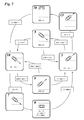
- the locating system 30 shown in FIG Sensor components a radar sensor 32 and a video camera 34, which are installed in a vehicle 36 ( Figure 2) that they Watch the apron of the vehicle.
- An evaluation unit 38 of Location system holds a data processing unit 40 for the Data of the radar sensor 32, an image processing unit 4 2 for the pictures taken by the video camera 34, a tracking Module 44 and a state machine 46, which as Recognition device for inputs and Ausschervor bland is used.
- the Data conditioning unit 30 calculated by the radar sensor 32 signals supplied the location data from the radar sensor located objects, in particular the vehicles in front. These location data are the distances and Relative velocities of the objects as well as the azimuth angles, under which the objects with respect to the longitudinal axis of Vehicle appear.
- This location data is periodically, with a predetermined clock cycle, to the tracking module 44 transmitted.
- the image processing unit 42 extracts from the Image data additional information that I s on the geometry refer to the located objects as well as to the roadway geometry.
- the object-related data are sent to the tracking module 44 transmitted while the lane data to the state machine 46 are transmitted.
- the tracking module 44 is adapted to a known algorithm obtained in the current measurement cycle Locate data with the data from previous cycles compare and locate the objects located in the current cycle Identify the previously located objects, so that the Objects can be tracked over a longer period of time. In this context, the tracking module creates a list all located objects, and this list will also be sent to the State machines 46 pass.
- State machine 46 serves to locate the located objects Assign different lanes to the lane and in particular to recognize entry and Ausschervor bland. The ones from Tracking module and provided by the state machine 46 Information will then be used for further evaluation Driver assistance system 48 transmitted, for example, an ACC System (Adaptive Cruise Control) for automatic Distance control.
- ACC System Adaptive Cruise Control
- FIG. 2 these are equipped with the location system 30 Vehicle 36 and another vehicle 50 schematically in one x-y coordinate system shown.
- the x-axis runs in Driving direction, ie in the direction of the longitudinal axis of the vehicle 16, and the y-axis is perpendicular to it.
- the road markings 52, 54 located, the the left and right limits of the driving tube, d. h., the indicate the lane traveled by the vehicle 36.
- the radar sensor 32 receives a radar echo from the back of the Vehicle 50, made up of the distance x and the Relative speed (in x-direction) and the azimuth angle of the vehicle 50, more specifically, an unspecified Calculate the reflection center at the rear of this vehicle to let. From the distance and the azimuth angle can also be approximate value for the lateral position, d. H. the y-coordinate of the vehicle 50.
- the image processing unit 42 provides more accurate values kante_l and edge_r for the y-coordinates of the left and right edges of the vehicle 50.
- image processing of the vehicle Course of the lane markings 52, 54 each as a function y (x) is calculated.
- Spur_l and spur_r indicate the location of the Road markings 52, 54, d. h., the limits of Driving hose at the location of the vehicle 50 at. In the state machine 46, these quantities are compared to edge_l and edge_r to to decide on which lane of the lane the vehicle is 50 is located.
- a shearing of the vehicle 50 in the Driving line between the lane markings 52 and 54 is also the probable relationship between kante_l and kante_r on the one hand and spur_l and spur_r on the other hand to a particular point of interest in the future.
- a prediction width pw defined, preferably in Dependence on the intrinsic speed of the vehicle 36.
- the vectorial Absolute velocity V of the vehicle 50 determined.
- the relative velocity measured by the radar sensor with the Airspeed of the vehicle 36 provides the x-component Vx of the vehicle 50.
- the y-component Vy is obtained by Differentiation of edge_l and / or edge_r according to time. Vectorial addition of these velocity components Vx and Vy supplies the sought velocity vector V.
- the left lane marker 52 and a straight line 56 drawn.
- the line 56 is a tangent to the Road marking 52 at the location of the vehicle 50th
- the Velocity vector V is drawn here so that Origin at the point of contact of the lane marker 52 and the Straight line 56 is located.
- the velocity vector V forms with the Line 56 an angle ⁇ , which can be determined by calculation. In the example shown, the angle ⁇ indicates that the Vehicle 50 on the road marking 52 and thus on the Ride the vehicle 36 to move.
- the State machines 46 periodically retrieve the location data of all located objects (vehicles) evaluated.
- the evaluation cycle the state machine 46 can from the measurement cycle of Data processing unit 40 and the image processing unit 42 can be different, but sync with it be, so that the evaluation in the state machine 46 always takes place when new location data is available.
- the state generator has thirteen in the example shown defines different states that each located object can accept. These states are characterized by Condition parameters ⁇ 20, ⁇ 17, ⁇ 13, ⁇ 10, ⁇ 7, ⁇ 3 and 0. On positive sign of the state parameter indicates that the object in question on the left side of the Reachway center is located, and a negative sign features states to the right of the passageway center. In Figure 4 are only the positive states for the left Lane shown. For the states not shown for the right lane, the following discussion applies analogously.
- the states ⁇ 20, ⁇ 10 and 0 are base states indicating where the object is located without a prediction for the Future is taken into account.
- the state is 20 characterized by the condition kan te_r> spur_l, d. h., that The object is located on the left side of the driving lane Adjacent lane.
- the conditions kante_l> spur_l apply and edge_r> track_r, d. h., the object is in Driving tube.
- the condition kan te_r ⁇ spur_l applies and kante_l> spur_l, d. h., the object is on the left driving line border.
- the object changes to state 7
- the object is then located on the left lane marker 52 and moves further into the own driving tube.
- This Shearing is reported to the assistance system 48 and For example, this system causes the speed of the Vehicle 36 to reduce to a sufficient Safety distance to the einscherenden vehicle build.
- the transition state 7 can only leave in two ways be either in the state 0, if the object is actually retracted, or back to state 10, when the object moves back to the left secondary lane (pred-edge_l> pred_spur_l).
- the base state 0 is only a change to state 3 or -3 possible.
- the change to state 3 takes place when The vehicle approaches the left lane boundary again (pred_edge_l> pred_track_l). Then return to the object Back in the middle of the driving tube, the state changes again to 0. Otherwise, state 10 is reached when the left Edge of the object crosses the lane marking.
- the object changes to state 13, the Again, a transitional state, this time for the Ausscheren of Object from the driving tube.
- the state 13 is left either towards state 10 (pred_edge -r ⁇ pred_track_l) or in the direction of state 20 (edge_r> spur_l).
- the driver assistance system 48 receives the message that this Object expected not soon at the Distance control needs to be considered, so that the Vehicle 36 again selected on the driver Desired speed can be accelerated.
- the Transition states the states -7 for the shearing and -13 for the breaking out.
- the state parameters are selected in the example 1 shown in FIG. that they in the downstream driver assistance system 48 as Relevance parameters are used for the object in question can.
- FIG. 5 shows a diagram analogous to FIG. 4 for a modified embodiment.
- the main difference to the example of Figure 4 is in Figure 5 is that in each evaluation cycle of the state machine 46 first a New determination of the base state for each object takes place. Each object can therefore each of the five in each cycle Reach base states (middle column in FIG. 5), regardless of what condition it was before Has. If the object in this way one of the base states has reached, for example, the state 10, are still in the the same evaluation cycle the criteria (pred_edge_l ⁇ pred_track_l or pred_edge_r> pred_spur_l) for switching to one of assigned states (7 or 13) checked, and depending on the result the object changes to one of the states 7, 13 or it remains in condition 10.
- pred_edge_l pred_track_l or pred_edge_r> pred_spur_l
- FIG. 6 illustrates a development of the embodiment according to FIG Figure 5, in the additional states and transition criteria are defined. For example, if an object is in one certain evaluation cycle has entered the base state 20 and then due to the condition pred_edge_r ⁇ pred_spur_l in the state 17 passes, so it can continue from this state go to state 15, though the condition pred_edge_l ⁇ pred_track_l is satisfied. In this state 15 the object is still outside the Ride tube, but it still approaches the drive line limit more emphatic than in state 17, since this is a stricter one Condition is met. The state 15 therefore has for the Driver assistance system 48 a higher relevance.
- the Criteria for state change not on the evaluation of Localization data for the object in question.
- additional criterion would be, for example, the setting of the Direction indicator (turn signal left or right) in Consider that recognized by the image processing unit 42 can be.
- This criterion can, for. B. consideration by defining additional states or by depending on this criterion, the prediction width pw is varied for the object in question.
- a bigger one Prediction range has z. B. consequence that the system more sensitive to transversal movements of the object.
- Figure 7 shows an embodiment adapted to locating systems, which provide no width information, but for example Systems which use only the radar sensor 32 as the sensor component contain.
- FIG. 7 illustrates a variant similar to FIG in FIG. 4 a first determination of the basic state only once, namely at the first detection of a new object takes place. Again, only the states are positive again State parameters shown, ie states that affect the refer to left secondary lane.
- the lateral position becomes an object here only by a zige measurement y which indicates the y-coordinate of the reflection center of the Indicates object.
- y As base states only the states occur here ⁇ 20 and 0 on.
- the object will be in the Basic state 20 classified. In this state becomes one Lane change parameter sw set to 0. From state 20 is only a change to the state 10 possible, namely, if y gets smaller than spur_l. When entering the state 10 will the lane change parameter sw increases by 1. If in the next Evaluation cycle of the state machine 46 is still the Condition y ⁇ spur_l is satisfied, the lane change parameter becomes sw increased by 1 again. This process is repeated until the lane change parameter has a certain threshold th exceeds (for example, 2). Then there is a transition from the state 10 in the state 7, the shearing in the Raceline features.
- th exceeds
- the state machine remains in state 0 as long as the state machine Conditions y ⁇ spur_l and y> spur_r are fulfilled. Likewise will an object is classified in the base state 0, if this Conditions fulfilled at the first location of the object are.
- the lane change parameter sw is reset to 0 in state 0 set.
- State 0 is exited in the direction of state 3, if the condition y> spur_l is fulfilled (or in the direction of the state -3, not shown, when the condition y ⁇ track_r is satisfied).
- the lane change parameter becomes gradually reduced as long as the condition y> spur_l is still satisfied until the lane change parameter the Threshold -th falls below. Falls below the Threshold value, a change to transitional state 13 takes place, which indicates an outbreak. On the state 13 takes place then again an immediate transition to state 20.
- condition 3 when in condition 3, the condition is pred ⁇ spur_l is detected, d. h., when the object returns approaches h, reaches a state 5 in which the meter is reset to 0. From here is one State 10 possible if the condition y ⁇ is, or a return to state 3, though prediction> spur_l is satisfied.
Landscapes
- Engineering & Computer Science (AREA)
- Radar, Positioning & Navigation (AREA)
- Remote Sensing (AREA)
- Computer Networks & Wireless Communication (AREA)
- Physics & Mathematics (AREA)
- General Physics & Mathematics (AREA)
- Traffic Control Systems (AREA)
Abstract
Description
- Figur 1
- ein Blockdiagramm eines erfindungsgemäßen Ortungssystems;
- Figuren 2 und 3
- Diagramme zur Erläuterung der Arbeits weise des Ortungssystems;
- Figur 4
- ein Diagramm eines Zustandsautomaten gemäß einer ersten Ausführungsform der Erfindung;
- Figur 5
- ein Diagramm eines Zustandsautomaten gemäß einer zweiten Ausführungsform;
- Figur 6
- eine Abwandlung des Zustandsautomaten gemäß Figur 5; und
- Figur 7
- ein Diagramm eines Zustandsautomaten gemäß einer weiteren Ausführungsform.
Claims (8)
- Objektortungssystem für Kraftfahrzeuge (36), mit einer Erkennungseinrichtung für Ein - und Ausschervorgänge, dadurch gekennzeichnet, daß die Erkennungseinrichtung einen Zustandsautomaten (46) aufweist, der jedem georteten Objekt (50) einen von mehreren vordefinierten, auf die Querposition des Objekts bezogenen Zuständen (20, 17, 13, 10, 7, 3, 0) zuweist und die Zustandszuweisungen wiederholt nach vorbestimmten Regeln anhand der jeweils neuesten Ortungsdaten aktualisiert, und daß mindestens einer der vordefinierten Zustände ein Übergangszustand (13, 7) ist, der einen Ein- oder Ausschervorgang kennzeichnet.
- Objektortungsystem nach Anspruch 1, dadurch gekennzeichnet, daß der Zustandsautomat (46) dazu ausgebildet ist, den einem Objekt zugewiesenen Zustand nach vorgegebenen Regeln zu ändern, wobei diese Regeln für jeden Zustandswechsel ein Kriterium beinhalten, das von den Ortungsdaten zu erfüllen ist, und daß sich mindestens eines dieser Kriterien auf einen aus den Bewegungsdaten des Objekts berechneten Vorhersagewert (präd_kante_l, präd_kante_r; präd) für die Querposit ion des Objekts bezieht.
- Objektortungssystem nach Anspruch 2, dadurch gekennzeichnet, daß das Objektortungssystem dazu ausgebildet ist, den voraussichtlichen Verlauf linker und rechter Grenzen (52, 54) der von dem eigenen Fahrzeug (36) befahrenen Fahrspur zu bestimmen, und daß das Kriterium, das sich auf den Vorhersagewert bezieht, eine vorgegebene Beziehung zwischen dem Vorhersagewert (präd_kante_l, präd_kante_r) und einen entsprechenden Vorhersagewert (präd_spur_l, präd_spur_r) für die Lage der Fahrsp urgrenze definiert.
- Objektortungssystem nach Anspruch 2 oder 3, dadurch gekennzeichnet, daß der Zustandsautomat (46) dazu ausgebildet ist, eine Prädiktionsweite (pw), die der Berechnung der Vorhersagewerte zugrunde liegt, geschwindigkeitsabhängig zu variieren.
- Objektortungssystem nach einem der vorstehenden Ansprüche, dadurch gekennzeichnet, daß die vordefinierten Zustände mehrere Basiszustände (20, 10 ,0) umfassen, daß die übrigen Zustände (17, 13, 7, 3) nur über einen der Basiszustände erreichbar sind und daß der Zustandsautomat (46) dazu ausgebildet ist, einem Objekt einen Basiszustand zuzuweisen, wenn es erstmals geortet wird, und bei den nachfolgenden Aktualisierungen der Zustandszuweisungen für dieses Objekt den Zustand nach Maßgabe der vorbestimmten Regeln in Abhängigkeit vom bisherigen Zustand zu ändern.
- Objektortungssystem nach einem der Ansprüche 1 bis 4, dadurch gekennzeichnet, daß die vordefinierten Zustände mehrere Basiszustände (20, 10, 0, -10, -20) umfassen, daß die übrigen Zustände jeweils nur über einen der Basiszustände erreichbar sind, und daß der Zustandsautomat (46) dazu ausgebildet ist, jedem Objekt bei jeder Aktualisierung zunächst einen der Basiszustände und dann nach Maßgabe vorgegebener Regeln einen der anderen Zustände zuzuweisen oder es in dem Basiszustand zu belassen.
- Objektortungssystem nach einem der vorstehenden Ansprüche, dadurch gekennzeichnet, daß es eine Sensorkomponente (34) enthält, mit der sich Breiteninformation über die georteten Objekte gewinnen läßt, und d aß die Ortungsdaten Größen (kante_l, kante_r) umfassen, die die Querpositionen der linken und rechten Kanten des Objekts angeben.
- Objektortungssystem nach einem der Ansprüche 1 bis 6, dadurch gekennzeichnet, daß der Zustandsautomat (46) dazu ausgebildet ist, bei jeder Aktualisierung der Zustandszuweisung einen Spurwechselparameter (sw) abhängig von den Ortungsdaten um eine bestimmtes Inkrement zu erhöhen oder zu verringern oder auf null zurückzusetzen und einem Objekt nur dann einen Übergangszustand (13, 7) zuzuweisen, wenn der Spurwechselparameter einen bestimmten Schwellenwert (th, -th) über- oder unterschreitet.
Applications Claiming Priority (2)
| Application Number | Priority Date | Filing Date | Title |
|---|---|---|---|
| DE102004013818A DE102004013818A1 (de) | 2004-03-20 | 2004-03-20 | Objektortungssystem für Kraftfahrzeuge |
| DE102004013818 | 2004-03-20 |
Publications (2)
| Publication Number | Publication Date |
|---|---|
| EP1577682A1 true EP1577682A1 (de) | 2005-09-21 |
| EP1577682B1 EP1577682B1 (de) | 2010-09-08 |
Family
ID=34833220
Family Applications (1)
| Application Number | Title | Priority Date | Filing Date |
|---|---|---|---|
| EP05100163A Expired - Lifetime EP1577682B1 (de) | 2004-03-20 | 2005-01-13 | Objektortungssystem für Kraftfahrzeuge zur Erkennung eines Spurwechsels |
Country Status (2)
| Country | Link |
|---|---|
| EP (1) | EP1577682B1 (de) |
| DE (2) | DE102004013818A1 (de) |
Cited By (11)
| Publication number | Priority date | Publication date | Assignee | Title |
|---|---|---|---|---|
| RU2403590C2 (ru) * | 2008-10-27 | 2010-11-10 | Государственное образовательное учреждение высшего профессионального образования Тамбовское высшее военное авиационное инженерное училище радиоэлектроники (военный институт) | Способ помехозащищенного обнаружения маневра воздушной цели |
| EP2275318A1 (de) * | 2009-07-15 | 2011-01-19 | Audi Ag | Verfahren zur Ermittlung eines Ein- oder Ausschervorgangs eines dem eigenen Kraftfahrzeug vorausfahrenden Fahrzeugs |
| EP2287060A1 (de) * | 2009-08-19 | 2011-02-23 | Audi AG | Verfahren zur Ermittlung eines Ein- oder Ausschervorgangs eines dem eigenen Kraftfahrzeug vorausfahrenden Fahrzeugs |
| US7991550B2 (en) * | 2006-02-03 | 2011-08-02 | GM Global Technology Operations LLC | Method and apparatus for on-vehicle calibration and orientation of object-tracking systems |
| US8914181B2 (en) | 2010-12-29 | 2014-12-16 | Siemens S.A.S. | System and method for active lane-changing assistance for a motor vehicle |
| EP3007150A1 (de) | 2014-10-07 | 2016-04-13 | Autoliv Development AB | Spurwechselerkennung |
| WO2016162256A1 (de) * | 2015-04-07 | 2016-10-13 | Lucas Automotive Gmbh | Steuerungs-system und verfahren zum ermöglichen eines einscherens eines anderen kraftfahrzeugs aus einer nachbarspur im acc-betrieb des eigenen kraftfahrzeugs |
| WO2019243162A1 (de) * | 2018-06-20 | 2019-12-26 | Robert Bosch Gmbh | Verfahren und fahrassistenzsystem zum vermeiden einer kollision eines fahrzeugs mit einem hindernis |
| CN111413692A (zh) * | 2020-03-18 | 2020-07-14 | 东风汽车集团有限公司 | 一种基于路旁静止物体的摄像头横向位置估测自标定方法 |
| CN113498519A (zh) * | 2019-03-05 | 2021-10-12 | 宝马汽车股份有限公司 | 用于识别拐入车辆或拐出车辆的方法及控制单元 |
| WO2022033651A1 (en) * | 2020-08-10 | 2022-02-17 | Dr. Ing. H.C. F. Porsche Aktiengesellschaft | Device for and method of aiding lane changing |
Families Citing this family (15)
| Publication number | Priority date | Publication date | Assignee | Title |
|---|---|---|---|---|
| DE102004047084A1 (de) | 2004-09-29 | 2006-03-30 | Robert Bosch Gmbh | Fahrerassistenzsystem mit Fuzzy-Logic |
| DE102006049246B4 (de) * | 2006-10-19 | 2021-04-15 | Robert Bosch Gmbh | Vorrichtung zur Erkennung von Ein- und Ausscherern in einem Fahrerassistenzsystem |
| DE102007013992A1 (de) * | 2007-03-23 | 2008-08-28 | Siemens Ag | Fahrerassistenzsystem mit Abstandsregeltempomat |
| DE102007029483B4 (de) | 2007-06-26 | 2022-07-07 | Robert Bosch Gmbh | Abstandsregelvorrichtung für Kraftfahrzeuge, mit Erkennung von Einscherern |
| DE102008005314A1 (de) | 2008-01-21 | 2009-07-23 | Robert Bosch Gmbh | Verfahren und Vorrichtung zum Erfassen eines vorbeifahrenden Fahrzeuges bei Dunkelheit |
| DE102011102437A1 (de) * | 2011-05-25 | 2012-11-29 | Audi Ag | Verfahren zum Betrieb eines längsführenden Fahrerassistenzsystems eines Kraftfahrzeugs und Kraftfahrzeug |
| US9412277B2 (en) * | 2014-10-13 | 2016-08-09 | Ford Global Technologies, Llc | Vehicle cut-in strategy |
| JP6325425B2 (ja) * | 2014-11-28 | 2018-05-16 | 株式会社デンソー | 車両制御装置 |
| JP6404722B2 (ja) * | 2015-01-21 | 2018-10-17 | 株式会社デンソー | 車両の走行制御装置 |
| DE102016106983A1 (de) * | 2016-04-15 | 2017-10-19 | Valeo Schalter Und Sensoren Gmbh | Verfahren zum Erkennen eines möglichen Spurwechselmanövers eines Zielfahrzeugs, Steuereinrichtung, Fahrerassistenzsystem sowie Kraftfahrzeug |
| US10077050B2 (en) * | 2016-05-24 | 2018-09-18 | GM Global Technology Operations LLC | Automated driving system for evaluating lane cut-out and method of using the same |
| JP6774297B2 (ja) | 2016-10-17 | 2020-10-21 | 株式会社デンソー | 車両認識装置及び車両認識方法 |
| US11488424B2 (en) | 2020-03-19 | 2022-11-01 | Toyota Motor North America, Inc. | Motion-based transport assessment |
| US11097735B1 (en) | 2020-03-19 | 2021-08-24 | Toyota Motor North America, Inc. | Transport lane usage |
| US11720114B2 (en) | 2020-03-19 | 2023-08-08 | Toyota Motor North America, Inc. | Safety of transport maneuvering |
Citations (5)
| Publication number | Priority date | Publication date | Assignee | Title |
|---|---|---|---|---|
| DE4313568C1 (de) * | 1993-04-26 | 1994-06-16 | Daimler Benz Ag | Verfahren zur Leithilfe für einen Fahrspurwechsel durch ein Kraftfahrzeug |
| EP0915350A2 (de) * | 1997-11-06 | 1999-05-12 | DaimlerChrysler AG | Vorrichtung zur Ermittlung fahrspurverlaufsindikativer Daten |
| EP0934846A2 (de) * | 1998-02-07 | 1999-08-11 | Volkswagen Aktiengesellschaft | Verfahren zur automatischen Abstandsregelung von Kraftfahrzeugen |
| DE10125426A1 (de) * | 2001-05-25 | 2002-11-28 | Bosch Gmbh Robert | Warnsystem und Verfahren zur Überwachung eines toten Winkels für ein Fahrzeug |
| US6674394B1 (en) * | 2003-03-28 | 2004-01-06 | Visteon Global Technologies, Inc. | Method for determining object location from side-looking sensor data |
-
2004
- 2004-03-20 DE DE102004013818A patent/DE102004013818A1/de not_active Withdrawn
-
2005
- 2005-01-13 DE DE502005010196T patent/DE502005010196D1/de not_active Expired - Lifetime
- 2005-01-13 EP EP05100163A patent/EP1577682B1/de not_active Expired - Lifetime
Patent Citations (5)
| Publication number | Priority date | Publication date | Assignee | Title |
|---|---|---|---|---|
| DE4313568C1 (de) * | 1993-04-26 | 1994-06-16 | Daimler Benz Ag | Verfahren zur Leithilfe für einen Fahrspurwechsel durch ein Kraftfahrzeug |
| EP0915350A2 (de) * | 1997-11-06 | 1999-05-12 | DaimlerChrysler AG | Vorrichtung zur Ermittlung fahrspurverlaufsindikativer Daten |
| EP0934846A2 (de) * | 1998-02-07 | 1999-08-11 | Volkswagen Aktiengesellschaft | Verfahren zur automatischen Abstandsregelung von Kraftfahrzeugen |
| DE10125426A1 (de) * | 2001-05-25 | 2002-11-28 | Bosch Gmbh Robert | Warnsystem und Verfahren zur Überwachung eines toten Winkels für ein Fahrzeug |
| US6674394B1 (en) * | 2003-03-28 | 2004-01-06 | Visteon Global Technologies, Inc. | Method for determining object location from side-looking sensor data |
Cited By (15)
| Publication number | Priority date | Publication date | Assignee | Title |
|---|---|---|---|---|
| US7991550B2 (en) * | 2006-02-03 | 2011-08-02 | GM Global Technology Operations LLC | Method and apparatus for on-vehicle calibration and orientation of object-tracking systems |
| RU2403590C2 (ru) * | 2008-10-27 | 2010-11-10 | Государственное образовательное учреждение высшего профессионального образования Тамбовское высшее военное авиационное инженерное училище радиоэлектроники (военный институт) | Способ помехозащищенного обнаружения маневра воздушной цели |
| EP2275318A1 (de) * | 2009-07-15 | 2011-01-19 | Audi Ag | Verfahren zur Ermittlung eines Ein- oder Ausschervorgangs eines dem eigenen Kraftfahrzeug vorausfahrenden Fahrzeugs |
| EP2287060A1 (de) * | 2009-08-19 | 2011-02-23 | Audi AG | Verfahren zur Ermittlung eines Ein- oder Ausschervorgangs eines dem eigenen Kraftfahrzeug vorausfahrenden Fahrzeugs |
| US8914181B2 (en) | 2010-12-29 | 2014-12-16 | Siemens S.A.S. | System and method for active lane-changing assistance for a motor vehicle |
| WO2016056976A1 (en) * | 2014-10-07 | 2016-04-14 | Autoliv Development Ab | Lane change detection |
| EP3007150A1 (de) | 2014-10-07 | 2016-04-13 | Autoliv Development AB | Spurwechselerkennung |
| US9886858B2 (en) | 2014-10-07 | 2018-02-06 | Autoliv Development Ab | Lane change detection |
| WO2016162256A1 (de) * | 2015-04-07 | 2016-10-13 | Lucas Automotive Gmbh | Steuerungs-system und verfahren zum ermöglichen eines einscherens eines anderen kraftfahrzeugs aus einer nachbarspur im acc-betrieb des eigenen kraftfahrzeugs |
| CN107438545A (zh) * | 2015-04-07 | 2017-12-05 | 卢卡斯汽车股份有限公司 | 用于在一个人自己的机动车辆的acc操作期间允许另一机动车辆从相邻车道前方开进的控制系统和方法 |
| WO2019243162A1 (de) * | 2018-06-20 | 2019-12-26 | Robert Bosch Gmbh | Verfahren und fahrassistenzsystem zum vermeiden einer kollision eines fahrzeugs mit einem hindernis |
| CN113498519A (zh) * | 2019-03-05 | 2021-10-12 | 宝马汽车股份有限公司 | 用于识别拐入车辆或拐出车辆的方法及控制单元 |
| CN111413692A (zh) * | 2020-03-18 | 2020-07-14 | 东风汽车集团有限公司 | 一种基于路旁静止物体的摄像头横向位置估测自标定方法 |
| CN111413692B (zh) * | 2020-03-18 | 2022-03-18 | 东风汽车集团有限公司 | 一种基于路旁静止物体的摄像头横向位置估测自标定方法 |
| WO2022033651A1 (en) * | 2020-08-10 | 2022-02-17 | Dr. Ing. H.C. F. Porsche Aktiengesellschaft | Device for and method of aiding lane changing |
Also Published As
| Publication number | Publication date |
|---|---|
| EP1577682B1 (de) | 2010-09-08 |
| DE502005010196D1 (de) | 2010-10-21 |
| DE102004013818A1 (de) | 2005-10-06 |
Similar Documents
| Publication | Publication Date | Title |
|---|---|---|
| EP1577682B1 (de) | Objektortungssystem für Kraftfahrzeuge zur Erkennung eines Spurwechsels | |
| DE102006027326B4 (de) | Spurwechselassistent für Kraftfahrzeuge | |
| EP1940665B1 (de) | Abstands- und geschwindigkeitsregler mit stauerkennung | |
| DE19637053C2 (de) | Verfahren und Vorrichtung zur automatischen Erkennung von Rechts- oder Linksverkehr | |
| EP1671196B1 (de) | Verfahren und vorrichtung zur fahrspurerkennung für ein fahrzeug | |
| EP1913452A1 (de) | Verfahren zur erkennung eines abbiegevorgangs und fahrerassistenzsystem für kraftfahrzeuge | |
| DE112009005097B4 (de) | Fahrzeuginformationsverarbeitungsvorrichtung | |
| DE10133945A1 (de) | Verfahren und Vorrichtung zum Austausch und zur Verarbeitung von Daten | |
| EP3495840A1 (de) | Verfahren und vorrichtung zur eigenlokalisierung eines fahrzeugs | |
| WO2006122867A1 (de) | Spurwechselassistent für kraftfahrzeuge | |
| DE102013210928A1 (de) | Verfahren zur Unterscheidung zwischen echten Hindernissen und Scheinhindernissen in einem Fahrerassistenzsystem für Kraftfahrzeuge | |
| EP1690730B1 (de) | Fahrerassistenzsystem mit redundanter Entscheidungseinheit | |
| DE112022001191T5 (de) | Automatische notbremsvorrichtung | |
| DE102004028591A1 (de) | Verfahren zum Bereitstellen von fahrstreckenabhängigen Informationen | |
| EP3411729A1 (de) | Verfahren zur erkennung und identifikation eines fahrmanövers eines verkehrsteilnehmers und kraftfahrzeug | |
| EP1900586B1 (de) | Abstandsregelvorrichtung mit Zielobjektanzeige | |
| DE102010003375B4 (de) | Umfeldbewertungssystem in einem Fahrzeug mit Sensormitteln zur Erfassung von Objekten im Umfeld des Fahrzeuges | |
| DE19828160B4 (de) | Verfahren zum automatischen Erkennen der Hauptrichtungsfahrbahn bei einer mehrspurigen Strecke | |
| WO2006087282A1 (de) | Verfahren zur erkennung eines bevorstehenden überholvorgangs | |
| WO2008040607A1 (de) | Fahrerassistenzsystem und verfahren zum verfolgen von georteten objekten | |
| EP1643269A1 (de) | Fahrerassistenzsystem mit Fuzzy-Logic | |
| DE10335898A1 (de) | Vorrichtung zur Bewertung von stehenden Objekten in einem Fahrerassistenzsystem | |
| DE102005005970A1 (de) | Fahrerassistenzystem mit Vorrichtung zur Erkennung von Sondersituationen | |
| EP1829760B1 (de) | Fahrerassistenzsystem mit Kursprädiktionsmodul | |
| WO2007019988A1 (de) | Verfahren zur bestimmung eines fahrschlauchs innerhalb dem sich ein fahrzeug mit grosser wahrscheinlichkeit fortbewegt |
Legal Events
| Date | Code | Title | Description |
|---|---|---|---|
| PUAI | Public reference made under article 153(3) epc to a published international application that has entered the european phase |
Free format text: ORIGINAL CODE: 0009012 |
|
| AK | Designated contracting states |
Kind code of ref document: A1 Designated state(s): AT BE BG CH CY CZ DE DK EE ES FI FR GB GR HU IE IS IT LI LT LU MC NL PL PT RO SE SI SK TR |
|
| AX | Request for extension of the european patent |
Extension state: AL BA HR LV MK YU |
|
| 17P | Request for examination filed |
Effective date: 20060321 |
|
| AKX | Designation fees paid |
Designated state(s): DE FR GB |
|
| GRAP | Despatch of communication of intention to grant a patent |
Free format text: ORIGINAL CODE: EPIDOSNIGR1 |
|
| GRAC | Information related to communication of intention to grant a patent modified |
Free format text: ORIGINAL CODE: EPIDOSCIGR1 |
|
| GRAC | Information related to communication of intention to grant a patent modified |
Free format text: ORIGINAL CODE: EPIDOSCIGR1 |
|
| GRAS | Grant fee paid |
Free format text: ORIGINAL CODE: EPIDOSNIGR3 |
|
| GRAA | (expected) grant |
Free format text: ORIGINAL CODE: 0009210 |
|
| AK | Designated contracting states |
Kind code of ref document: B1 Designated state(s): DE FR GB |
|
| REG | Reference to a national code |
Ref country code: GB Ref legal event code: FG4D Free format text: NOT ENGLISH |
|
| REF | Corresponds to: |
Ref document number: 502005010196 Country of ref document: DE Date of ref document: 20101021 Kind code of ref document: P |
|
| PLBE | No opposition filed within time limit |
Free format text: ORIGINAL CODE: 0009261 |
|
| STAA | Information on the status of an ep patent application or granted ep patent |
Free format text: STATUS: NO OPPOSITION FILED WITHIN TIME LIMIT |
|
| 26N | No opposition filed |
Effective date: 20110609 |
|
| REG | Reference to a national code |
Ref country code: DE Ref legal event code: R097 Ref document number: 502005010196 Country of ref document: DE Effective date: 20110609 |
|
| REG | Reference to a national code |
Ref country code: FR Ref legal event code: PLFP Year of fee payment: 12 |
|
| PGFP | Annual fee paid to national office [announced via postgrant information from national office to epo] |
Ref country code: GB Payment date: 20160122 Year of fee payment: 12 Ref country code: FR Payment date: 20160121 Year of fee payment: 12 |
|
| GBPC | Gb: european patent ceased through non-payment of renewal fee |
Effective date: 20170113 |
|
| REG | Reference to a national code |
Ref country code: FR Ref legal event code: ST Effective date: 20170929 |
|
| PG25 | Lapsed in a contracting state [announced via postgrant information from national office to epo] |
Ref country code: FR Free format text: LAPSE BECAUSE OF NON-PAYMENT OF DUE FEES Effective date: 20170131 |
|
| PG25 | Lapsed in a contracting state [announced via postgrant information from national office to epo] |
Ref country code: GB Free format text: LAPSE BECAUSE OF NON-PAYMENT OF DUE FEES Effective date: 20170113 |
|
| REG | Reference to a national code |
Ref country code: DE Ref legal event code: R084 Ref document number: 502005010196 Country of ref document: DE |
|
| PGFP | Annual fee paid to national office [announced via postgrant information from national office to epo] |
Ref country code: DE Payment date: 20200324 Year of fee payment: 16 |
|
| REG | Reference to a national code |
Ref country code: DE Ref legal event code: R119 Ref document number: 502005010196 Country of ref document: DE |
|
| PG25 | Lapsed in a contracting state [announced via postgrant information from national office to epo] |
Ref country code: DE Free format text: LAPSE BECAUSE OF NON-PAYMENT OF DUE FEES Effective date: 20210803 |