EP1577447B1 - Dispositif hydraulique de commande pour pelle hydraulique - Google Patents
Dispositif hydraulique de commande pour pelle hydraulique Download PDFInfo
- Publication number
- EP1577447B1 EP1577447B1 EP05102015A EP05102015A EP1577447B1 EP 1577447 B1 EP1577447 B1 EP 1577447B1 EP 05102015 A EP05102015 A EP 05102015A EP 05102015 A EP05102015 A EP 05102015A EP 1577447 B1 EP1577447 B1 EP 1577447B1
- Authority
- EP
- European Patent Office
- Prior art keywords
- confluence
- valve
- control valve
- boom
- arm
- Prior art date
- Legal status (The legal status is an assumption and is not a legal conclusion. Google has not performed a legal analysis and makes no representation as to the accuracy of the status listed.)
- Not-in-force
Links
Images

Classifications
-
- E—FIXED CONSTRUCTIONS
- E02—HYDRAULIC ENGINEERING; FOUNDATIONS; SOIL SHIFTING
- E02F—DREDGING; SOIL-SHIFTING
- E02F9/00—Component parts of dredgers or soil-shifting machines, not restricted to one of the kinds covered by groups E02F3/00 - E02F7/00
- E02F9/20—Drives; Control devices
- E02F9/22—Hydraulic or pneumatic drives
- E02F9/2221—Control of flow rate; Load sensing arrangements
- E02F9/2239—Control of flow rate; Load sensing arrangements using two or more pumps with cross-assistance
-
- E—FIXED CONSTRUCTIONS
- E02—HYDRAULIC ENGINEERING; FOUNDATIONS; SOIL SHIFTING
- E02F—DREDGING; SOIL-SHIFTING
- E02F9/00—Component parts of dredgers or soil-shifting machines, not restricted to one of the kinds covered by groups E02F3/00 - E02F7/00
- E02F9/20—Drives; Control devices
- E02F9/22—Hydraulic or pneumatic drives
- E02F9/2278—Hydraulic circuits
- E02F9/2285—Pilot-operated systems
-
- E—FIXED CONSTRUCTIONS
- E02—HYDRAULIC ENGINEERING; FOUNDATIONS; SOIL SHIFTING
- E02F—DREDGING; SOIL-SHIFTING
- E02F9/00—Component parts of dredgers or soil-shifting machines, not restricted to one of the kinds covered by groups E02F3/00 - E02F7/00
- E02F9/20—Drives; Control devices
- E02F9/22—Hydraulic or pneumatic drives
- E02F9/2278—Hydraulic circuits
- E02F9/2292—Systems with two or more pumps
-
- E—FIXED CONSTRUCTIONS
- E02—HYDRAULIC ENGINEERING; FOUNDATIONS; SOIL SHIFTING
- E02F—DREDGING; SOIL-SHIFTING
- E02F9/00—Component parts of dredgers or soil-shifting machines, not restricted to one of the kinds covered by groups E02F3/00 - E02F7/00
- E02F9/20—Drives; Control devices
- E02F9/22—Hydraulic or pneumatic drives
- E02F9/2278—Hydraulic circuits
- E02F9/2296—Systems with a variable displacement pump
Definitions
- the present invention relates to a hydraulic control system for controlling a hydraulic actuator for a hydraulic excavator.
- a front end of a bucket is brought into contact with the ground while a boom and an arm are extended to a maximum and then boom raising operation and arm pulling operation are performed simultaneously to pull the bucket toward the excavator.
- This known hydraulic excavator is configured in such a manner that the cylinder speed of a boom cylinder which is set for a fine operation taking the lifting work into account can be increased in the leveling work so as to permit operation at a speed matching a high arm speed.
- the boom whose speed is set for the fine operation can be actuated while allowing its speed to match the arm speed in the leveling work, but the excavator is not so configured as to permit an increase of the arm cylinder speed in the case where only the arm pulling operation is performed in the nearly vertical attitude of the arm.
- EP1146175 A describes a construction machine with a hydraulic control system according to the preamble of claim 1 in which upon simultaneous operation of rotating and arm pulling is detected by a detector, a switching controller recognizes that both signals are output simultaneously to switch a switching valve to a second opposition, so that pressure oil discharged from a plurality of hydraulic pumps are united and supplied to a rotating motor and an arm cylinder, and so designed that meter-in flow controller restricts a quantity of oil supplied to the arm cylinder.
- the hydraulic control system for a hydraulic excavator comprises, as a basic configuration thereof, a boom control valve adapted to provide pressure oil from a first hydraulic pump with a boom cylinder in accordance with operation of a boom operation means, the boom control valve being disposed in a first oil path, an boom control valve adapted to provide pressure oil from a second hydraulic pump with an arm cylinder in accordance with operation of an arm operation means, the arm control valve being disposed in a second oil path, a confluence switching valve adapted to switch between a confluence position for joining the pressure oil from the first and second oil paths and a confluence stop position for stopping the joining, a flow control valve disposed in a return oil path for returning the pressure oil present in the first oil path to a tank, and a control means for controlling the confluence switching valve and the flow control valve.
- the control means is configured so as to switch the confluence switching valve to the confluence position and to make the flow control valve in a closed position when the arm operating means is operated independently and so as to switch the confluence switching valve to the confluence stop position and to make the flow control valve in an opened position when arm operating means and boom operating means are operated substantially simultaneously.
- the respective cylinders of boom and arm can be operated each independently, and in case of performing the arm pulling operation alone, it is possible to increase the speed of the arm cylinder. Consequently, for example when the arm assumes a nearly vertical attitude and the arm speed becomes insufficient in a leveling work, it is possible to increase the flow rate of the pressure oil fed to the arm cylinder. As a result, the problem that the peripheral speed at a front end of a front attachment becomes low is solved and it is possible to improve the leveling work efficiency.
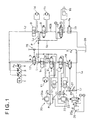
- Fig. 1 illustrates a hydraulic control circuit (hydraulic control system) in a hydraulic excavator according to a first embodiment of the present invention.
- the hydraulic excavator though not shown, comprises a lower traveling body and an upper rotating body mounted rotatably on the lower traveling body, with a front attachment being attached to a front portion of the upper rotating body.
- the front attachment comprises a boom, an arm and a bucket.
- a first hydraulic pump 2, a second hydraulic pump 3 and a pilot pump 4 for producing a pilot pressure Pa are actuated by operation of an engine 1.
- the first and second hydraulic pumps 2, 3 are variable capacity pumps. A discharge flow rate in each of the pumps varies in accordance with an inclination angle of a swash plate.
- Pressure oil discharged from the first and second hydraulic pumps 2, 3 is fed to a right traveling motor control valve 5, a bucket cylinder control valve 6 and a boom cylinder control valve (boom control valve) 7 which are disposed in a left center bypass line (first oil path) LCB and is also fed to a left traveling motor control valve 8, a swing motor control valve 9 and an arm cylinder control valve (arm control valve) 10 which are disposed in a right center bypass line (second oil path) RCB.
- a right traveling motor control valve 5 a bucket cylinder control valve 6 and a boom cylinder control valve (boom control valve) 7 which are disposed in a left center bypass line (first oil path) LCB and is also fed to a left traveling motor control valve 8, a swing motor control valve 9 and an arm cylinder control valve (arm control valve) 10 which are disposed in a right center bypass line (second oil path) RCB.
- a right traveling motor 11, a bucket cylinder 12, and a boom cylinder 13, are connected to the right traveling motor control valve 5, the bucket cylinder control valve 6, and the boom cylinder control valve 7, respectively, and pressure oil is fed to the respective actuators through the control valves.
- a left traveling motor 14, a swing motor 15, and an arm cylinder 16 are connected to the left traveling motor control valve 8, the swing motor control valve 9,and the arm cylinder control valve 10, respectively.
- a straight traveling valve (confluence switching valve) 17 is disposed in an upstream oil path L1 formed on the upstream of the right traveling motor control valve 5. When a leveling work to be described later is not performed, the straight traveling valve 17 is switched so as to ensure straight traveling stability as a conventional function.
- the straight traveling valve 17 has a flow dividing position a as a confluence stop position and a confluence position b and is normally held at the flow dividing position a.
- pressure oil discharged from the first hydraulic pump 2 is fed to the left center bypass line LCB through the oil path L1, while pressure oil discharged from the second hydraulic pump 3 is fed to the right center bypass line RCB through an oil path L2.
- the pressure oil from the first hydraulic pump 2 and the pressure oil from the second hydraulic pump 3 are fed each independently to the right traveling motor control valve 5 and the left traveling motor control valve 8.
- the pressure oil from the first hydraulic pump 2 is fed through an oil path L3.
- this oil path L3 is connected with an oil path L4 divided from a downstream side of the left traveling motor control valve 8 in the RCB.
- the pressure oil is provided with the swing motor control valve 9 and the arm control valve 10 through an oil path L5 extended from the connecting point P.
- a part of the pressure oil flowing in the path L3 is also able to be provided with the bucket cylinder control valve 6 and the boom cylinder control valve 7.
- the pressure oil from the second hydraulic pump 3 is divided to flows in parallel through the oil paths L1 and L2 and is fed and distributed to the left and right traveling motor control valves 8, 5.
- a composite operation such as, for example, a boom hoisting operation under operation of the right and left traveling motors 11, 14, the pressure oil from the second hydraulic pump 3 is fed equally to right and left traveling motors 11, 14, whereby the straight traveling stability can be ensured.
- a left cut-off valve (flow control valve) 18 is disposed on the downstream (return oil path) side of the boom cylinder control valve 7 in the left center bypass line LCB and a right cut-off valve 19 is disposed on the downstream side of the arm cylinder control valve 10 in the right center bypass line RCB.
- a bucket operating remote control valve 20 with a bucket operating lever 20a, a boom operating remote control valve (boom operating means) 22 with a boom operating lever 22a, and an arm operating lever 25a are connected.
- Those remote control valves 20, 22, 25 output a pilot pressure according to an operating direction and an operating amount of each of those operating levers 20a, 22a, 25a.
- Pilot pressures P1 and P2 outputted from the bucket operating remote control valve 20 are provided to respective pilot ports in the bucket cylinder control valve 6. Either the pilot pressure P1 or P2 is selected by a high-order selection which is made by a shuttle valve 21.
- the pilot pressure P1 (or P2) thus selected by the high-order selection and a boom raising pilot pressure P3 outputted from the boom operating remote control valve 22 are further subjected to a high-order selection by a shuttle valve (detecting means for detecting a boom raising operation pressure) 23. That is, the shuttle valves 21 and 23 are adapted to detect a composite operation.
- the pilot pressure selected by the shuttle valve 23 is provided to a pilot port of a flow control valve (control means) 24.
- the flow control valve 24 is adapted to be switched between a cut-off position c and a communicating position d and is normally held at the communicating position d.
- the arm pulling pilot pressure P4 outgoing from the flow control valve 24 is provided to a pilot port of the straight traveling valve 17 through an oil path L6 and a shuttle valve 26.
- the shuttle valve 26 makes a high-order selection out of a pilot pressure based on simultaneous operation of traveling operation and attachment operation and the arm pulling pilot pressure P4.
- An oil path L7 which branches from the oil path L6 is connected to a pilot port of the left cut-off valve 18 through a shuttle valve 27.
- the shuttle valve 27 makes a high-order selection out of an operating pressure other than the arm pulling pilot pressure (e.g., arm pushing pilot pressure) and the arm pulling pilot pressure P4.
- Numeral 28 in the figure denotes a return oil tank.
- the straight traveling valve 17 is used as a confluence switching valve.
- the straight traveling valve 17 makes switching between the flow dividing position a (first switching position) in which the pressure oil from the first hydraulic pump 2 and the pressure oil from the second hydraulic pump 3 are fed each independently to the LCB (first oil path) and RCB (second oil path) and thence to the traveling motor 11 disposed in the LCB as the first oil path and the traveling motor 14 disposed in the RCB as the second oil path, and the confluence position b (second switching position) in which the pressure oil from either the first hydraulic pump 2 or the second hydraulic pump 3 is distributed to the traveling motors 11 and 14.
- the effect of the present invention can be exhibited without any great design alteration of the existing circuit.
- the pilot pressure P4 is provided to the pilot port of the straight traveling valve 17 through the oil path L6 and is also provided to the pilot port of the left cut-off valve 18 through the oil path L7, whereby the straight traveling valve 17 switches from the flow dividing position a to the confluence position b and the left cut-off valve 18 switches from a communicating position e to a cut-off position f.
- the pressure oil from the first hydraulic pump 2 is fed to the arm cylinder control valve 10 through the oil paths L3 to L5.
- the pressure oil from the second hydraulic pump 3 flows through the oil paths L2 to L4 because the left cut-off valve 18 in LCB is closed, and in the oil path L5 it joins the pressure oil from the first hydraulic pump 2.
- the boom raising pilot pressure P3 is provided to the pilot port of the flow control valve 24 through the shuttle valve 23 and the flow control valve 24 is switched from the communicating position d to the cut-off position c.
- the flow control valve 24 When bucket excavation and bucket release are operated in the leveling work, the flow control valve 24 also switches from the communicating portion d to the cut-off position c upon receipt of the pilot pressure P1 (or P2).
- the straight traveling valve 17 and the left cut-off valve 18 are configured so as to be switched by ON-OFF operation (opening and closing operation).
- the straight traveling valve 17 and the left cut-off valve 18 are also configured so as to switch gradually in proportion to the operation amount of the boom operating lever 22a, instead of by ON-OFF operation. Therefore, the confluence and flow division can be switched from one to the other without causing any shock.
- the straight traveling valve 17 and the left cut-off valve 18 be configured so as to switch in proportion to the operation amount of the boom operating lever 22a. According to this configuration, in the arm pulling operation, the straight traveling valve 17 and the left cut-off valve 18 are switched gradually without any shock.
- the straight traveling valve 17 is switched to the flow dividing side and the left cut-off valve 18 is opened as the operation amount of the boom operating lever 22a increases, and thus a shock-free operation is ensured.
- the pump flow rate on the confluence side in the case of a negative control device, a negative control pressure drops and the flow rate increases upon closure of the left cut-off valve 18, while in the case of a positive control valve and if control is to be made hydraulically, the pump flow rate of the first hydraulic pump 2 can be increased with the pilot pressure which is for switching the straight traveling valve 17 and the left cut-off valve 18.
- the afore-mentioned flow control valve 24 and the shuttle valve 26 are constituted as a control means which is adapted to switch the position of the straight traveling valve 17 according to the condition of an arm operation and a boom operation.
- This straight traveling valve 17 serves as well for a confluence switching valve for switching supplying condition of the pressure oil from the pumps 2,3 to the boom cylinder control valve 7 and the arm cylinder control valve 10.
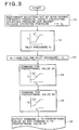
- Fig. 2 illustrates a second embodiment of the present invention, in which the above control for confluence and flow division is performed electrically using a controller.
- bucket pilot pressure sensors 30 and 31 are provided on the secondary side of a bucket operating remote control valve 20.
- a bucket excavation pilot pressure S1 and a bucket release pilot pressure S2 are outputted as electric signals from the sensors 30 and 31 respectively.
- a boom pilot pressure sensor (detecting means for detecting a boom raising operation pressure) 32 is provided on the secondary side (boom raising side) of a boom operating remote control valve 22 and a boom raising pilot pressure S3 is outputted from the sensor 32.
- the sensors 30 to 32 are adapted to detect a composite operation of actuators.
- an arm pilot pressure sensor 33 is provided on the secondary side (arm pulling side) of an arm operating remote control valve 25 and an arm pulling pilot pressure S4 is outputted from the sensor 33.
- the pilot pressures S1 to S4 are provided to a controller 34.
- the controller 34 controls a proportional valve 35 connected to a pilot port of a straight traveling valve 17 and also controls a left cut-off valve 18 through a proportional valve 36.
- the controller 34 and the proportional valve 36 function as control means.
- the controller 34 makes a high-order selection out of the boom raising pilot pressure S3, the bucket excavation pilot pressure S1 and the bucket release pilot pressure S2 (step S1). As a result, a pilot pressure as an operating pressure is selected and is made a pilot pressure f0.
- a map having a characteristic C1 such that a pressure f1 is kept to a minimum pressure in a region where the pilot pressure f0 selected by the high-order selection is less than a predetermined value and that the pressure f1 becomes higher as the pilot pressure f0 selected by the high-order selection rises.
- the pressure f1 corresponding to the selected pilot pressure f0 is determined on the basis of the map (step S2).
- This calculation aims at suppressing f2 and canceling a confluence command for the straight traveling valve 17 in case of arm pulling and boom raising (or bucket excavation/bucket release) operations being performed simultaneously.
- a confluence command I1 for the proportional valve 35 is calculated on the basis of a map of the confluence command I1 which has characteristic C2 increasing with an increase of the f2 (step S4).
- a closing command I2 for the proportional valve 36 is calculated on the basis of the closing command I2 which has characteristic C3 increasing with an increase of the f2 (step S5).
- step S6 the thus-determined confluence command I1 and closing command I2 are outputted to the proportional valves 35 and 36, respectively (step S6), whereby the straight traveling valve 17 and the left cut-off valve 18 are controlled.
Claims (4)
- Dispositif de commande hydraulique pour une pelle hydraulique, comprenant :une soupape de commande de flèche (7) adaptée pour proposer l'huile sous pression provenant d'une première pompe hydraulique (2) avec un vérin de flèche selon le fonctionnement des moyens de commande de flèche (22), ladite soupape de commande de flèche (7) étant disposée dans un premier passage (LCB) ;une soupape de commande de bras (10) adaptée pour fournir l'huile sous pression provenant d'une seconde pompe hydraulique (3) avec un vérin de bras selon le fonctionnement des moyens d'actionnement de bras (25a), ladite soupape de commande de bras (10) étant disposée dans un second passage d'huile (RCB) ;une soupape de commutation de confluence (17) adaptée pour passer d'une position de confluence pour réunir ladite huile sous pression provenant desdits premier et second passages d'huile et une position d'arrêt de confluence pour arrêter ladite réunion ;une soupape de commande d'écoulement (18), dans laquelle la soupape de commande d'écoulement (18) est disposée dans un passage d'huile de retour pour faire revenir ladite huile sous pression présente dans ledit premier passage d'huile dans un réservoir (28) ; et dans laquelle la pelle hydraulique comprend en outre :des moyens de commande (24) pour commander ladite soupape de commutation de confluence (17) et ladite soupape de commande d'écoulement (18), caractérisé par lesdits moyens de commande (24) qui sont configurés afin de faire passer ladite soupape de commutation de confluence (17) à la position de confluence et de faire passer ladite soupape de commande d'écoulement (18) dans une position fermée lorsque lesdits moyens d'actionnement de bras (25a) sont actionnés indépendamment afin de faire passer ladite soupape de commutation de confluence (17) dans la position d'arrêt de confluence et de faire passer ladite soupape de commande d'écoulement (18) dans une position ouverte lorsque lesdits moyens d'actionnement de bras (25a) et lesdits moyens d'actionnement de flèche (22) sont actionnés sensiblement simultanément.
- Dispositif de commande hydraulique pour une pelle hydraulique selon la revendication 1, comprenant en outre des moyens de détection (23) pour détecter une quantité d'opération de levage de flèche par lesdits moyens d'actionnement de flèche (22) et dans lequel lesdits moyens de commande (24) sont configurés afin de faire passer ladite soupape de commutation de confluence (17) dans la position de confluence et de faire passer ladite soupape de commande d'écoulement (18) dans la position fermée lorsque la quantité d'actionnement de levage de flèche détectée par lesdits moyens de détection (23) n'est pas supérieure à une valeur prédéterminée.
- Dispositif de commande hydraulique pour une pelle hydraulique selon la revendication 1, comprenant en outre des moyens de détection (23) pour détecter une quantité d'actionnement de levage de flèche par lesdits moyens d'actionnement de flèche (22) et dans lequel ladite soupape de commutation de confluence (17) et ladite soupape de commande d'écoulement (18) sont configurées afin d'être commutées entre ladite position de confluence et ladite position d'arrêt de confluence et entre ladite position ouverte et ladite position fermée proportionnellement à ladite quantité d'actionnement de levage de flèche par lesdits moyens d'actionnement de flèche (22).
- Dispositif de commande hydraulique pour une pelle hydraulique selon la revendication 1, dans lequel une soupape de translation droite (17) est prévue en tant que ladite soupape de commutation de confluence, ladite soupape de translation droite (17) étant adaptée pour réaliser une commutation entre une première position de commutation dans laquelle ladite huile sous pression provenant de ladite première pompe hydraulique (2) et ladite huile sous pression provenant de la seconde pompe hydraulique (3) sont alimentées indépendamment audit premier passage d'huile et audit second passage d'huile et par conséquent à un moteur de translation disposé dans ledit premier passage d'huile et un moteur de translation disposé dans ledit second passage d'huile et une seconde position de commutation dans laquelle ladite huile sous pression provenant de ladite première pompe hydraulique ou de ladite seconde pompe hydraulique est distribuée à chacun desdits moteurs de translation.
Applications Claiming Priority (2)
| Application Number | Priority Date | Filing Date | Title |
|---|---|---|---|
| JP2004078841 | 2004-03-18 | ||
| JP2004078841 | 2004-03-18 |
Publications (2)
| Publication Number | Publication Date |
|---|---|
| EP1577447A1 EP1577447A1 (fr) | 2005-09-21 |
| EP1577447B1 true EP1577447B1 (fr) | 2007-11-07 |
Family
ID=34836578
Family Applications (1)
| Application Number | Title | Priority Date | Filing Date |
|---|---|---|---|
| EP05102015A Not-in-force EP1577447B1 (fr) | 2004-03-18 | 2005-03-15 | Dispositif hydraulique de commande pour pelle hydraulique |
Country Status (4)
| Country | Link |
|---|---|
| US (1) | US7178333B2 (fr) |
| EP (1) | EP1577447B1 (fr) |
| AT (1) | ATE377676T1 (fr) |
| DE (1) | DE602005003151T2 (fr) |
Families Citing this family (27)
| Publication number | Priority date | Publication date | Assignee | Title |
|---|---|---|---|---|
| US7178333B2 (en) | 2004-03-18 | 2007-02-20 | Kobelco Construction Machinery Co., Ltd. | Hydraulic control system for hydraulic excavator |
| JP4655795B2 (ja) * | 2005-07-15 | 2011-03-23 | コベルコ建機株式会社 | 油圧ショベルの油圧制御装置 |
| JP4232784B2 (ja) * | 2006-01-20 | 2009-03-04 | コベルコ建機株式会社 | 作業機械の油圧制御装置 |
| JP4353190B2 (ja) * | 2006-02-27 | 2009-10-28 | コベルコ建機株式会社 | 建設機械の油圧回路 |
| CN101490425B (zh) * | 2006-05-15 | 2013-01-30 | 株式会社小松制作所 | 液压行驶车辆 |
| KR100753990B1 (ko) * | 2006-08-29 | 2007-08-31 | 볼보 컨스트럭션 이키프먼트 홀딩 스웨덴 에이비 | 주행직진용 유압회로 |
| KR100900436B1 (ko) * | 2007-05-21 | 2009-06-01 | 볼보 컨스트럭션 이키프먼트 홀딩 스웨덴 에이비 | 무한궤도형 중장비의 주행장치 |
| US8167089B2 (en) * | 2008-01-15 | 2012-05-01 | Bennu Parts And Service, Inc. | Liftable scaffold |
| JP4953325B2 (ja) * | 2009-03-12 | 2012-06-13 | キャタピラー エス エー アール エル | 作業機械 |
| CN101899850B (zh) * | 2010-07-29 | 2012-07-18 | 三一重机有限公司 | 一种降低挖掘机启动负载的控制方法及装置 |
| CN102140807B (zh) * | 2011-01-11 | 2012-05-23 | 徐州徐工挖掘机械有限公司 | 一种提高挖掘机挖掘操纵特性和平整作业特性的方法 |
| CN102140808B (zh) * | 2011-01-11 | 2012-05-23 | 徐州徐工挖掘机械有限公司 | 一种提高挖掘机挖掘操纵特性和平整作业特性的装置 |
| KR20140072835A (ko) * | 2011-05-11 | 2014-06-13 | 볼보 컨스트럭션 이큅먼트 에이비 | 하이브리드 액츄에이터의 급정지 장치가 구비되는 하이브리드 굴삭기 |
| EP2772653A4 (fr) * | 2011-10-07 | 2015-10-21 | Volvo Constr Equip Ab | Système de commande pour faire fonctionner un dispositif de travail d'une machine de construction |
| JP5805581B2 (ja) * | 2012-04-23 | 2015-11-04 | 住友建機株式会社 | 建設機械の油圧回路及びその油圧制御装置 |
| JP5758348B2 (ja) * | 2012-06-15 | 2015-08-05 | 住友建機株式会社 | 建設機械の油圧回路 |
| JP5778086B2 (ja) * | 2012-06-15 | 2015-09-16 | 住友建機株式会社 | 建設機械の油圧回路及びその制御装置 |
| JP6196499B2 (ja) * | 2013-08-20 | 2017-09-13 | ナブテスコ株式会社 | 建設機械の多連方向切換弁 |
| KR102128630B1 (ko) * | 2014-03-24 | 2020-06-30 | 두산인프라코어 주식회사 | 유압시스템에서 스윙 모터의 제어방법 및 유압시스템 |
| EP3290595B1 (fr) * | 2015-04-29 | 2021-02-17 | Volvo Construction Equipment AB | Appareil de régulation de débit d'engin de chantier et son procédé de commande |
| DE102016003972A1 (de) * | 2016-04-01 | 2017-10-05 | Hydac System Gmbh | Steuervorrichtung |
| JP6575916B2 (ja) * | 2016-08-17 | 2019-09-18 | 日立建機株式会社 | 作業車両 |
| CN106640820A (zh) * | 2017-01-22 | 2017-05-10 | 山东常林机械集团股份有限公司 | 多路控制阀 |
| EP3707389B1 (fr) * | 2017-11-08 | 2024-04-24 | Volvo Construction Equipment AB | Circuit hydraulique |
| US10677269B2 (en) | 2018-08-30 | 2020-06-09 | Jack K. Lippett | Hydraulic system combining two or more hydraulic functions |
| JP7165016B2 (ja) | 2018-10-02 | 2022-11-02 | 川崎重工業株式会社 | 油圧ショベル駆動システム |
| CN110230334A (zh) * | 2019-06-11 | 2019-09-13 | 徐州徐工挖掘机械有限公司 | 一种液压挖掘机智能平地装置及其控制方法 |
Family Cites Families (8)
| Publication number | Priority date | Publication date | Assignee | Title |
|---|---|---|---|---|
| GB2090383B (en) * | 1980-12-26 | 1984-08-30 | Kubota Ltd | Hydrostatic transmission for a tracked vehicle |
| JPH0791846B2 (ja) * | 1988-12-19 | 1995-10-09 | 株式会社小松製作所 | 油圧パワーショベルのサービス弁回路 |
| JP2697473B2 (ja) * | 1992-03-31 | 1998-01-14 | 油谷重工株式会社 | 建設機械の合流装置 |
| JP3425844B2 (ja) | 1996-09-30 | 2003-07-14 | コベルコ建機株式会社 | 油圧ショベル |
| JP4111286B2 (ja) * | 1998-06-30 | 2008-07-02 | コベルコ建機株式会社 | 建設機械の走行制御方法及び同装置 |
| JP3491600B2 (ja) | 2000-04-13 | 2004-01-26 | コベルコ建機株式会社 | 建設機械の油圧制御回路 |
| JP3614121B2 (ja) | 2001-08-22 | 2005-01-26 | コベルコ建機株式会社 | 建設機械の油圧装置 |
| US7178333B2 (en) | 2004-03-18 | 2007-02-20 | Kobelco Construction Machinery Co., Ltd. | Hydraulic control system for hydraulic excavator |
-
2005
- 2005-03-14 US US11/078,317 patent/US7178333B2/en not_active Expired - Fee Related
- 2005-03-15 AT AT05102015T patent/ATE377676T1/de not_active IP Right Cessation
- 2005-03-15 DE DE602005003151T patent/DE602005003151T2/de active Active
- 2005-03-15 EP EP05102015A patent/EP1577447B1/fr not_active Not-in-force
Also Published As
| Publication number | Publication date |
|---|---|
| EP1577447A1 (fr) | 2005-09-21 |
| DE602005003151T2 (de) | 2008-08-28 |
| DE602005003151D1 (de) | 2007-12-20 |
| US20050204734A1 (en) | 2005-09-22 |
| ATE377676T1 (de) | 2007-11-15 |
| US7178333B2 (en) | 2007-02-20 |
Similar Documents
| Publication | Publication Date | Title |
|---|---|---|
| EP1577447B1 (fr) | Dispositif hydraulique de commande pour pelle hydraulique | |
| EP1995155B1 (fr) | Dispositif de voyage pour équipement lourd de type chenille | |
| JP5388787B2 (ja) | 作業機械の油圧システム | |
| KR101932304B1 (ko) | 작업 기계의 유압 구동 장치 | |
| EP1512798B1 (fr) | Système de commande hydraulique pour engin de travaux publics | |
| EP1760326B1 (fr) | Commande hydraulique pour un engin de travaux public | |
| EP2719902A1 (fr) | Système hydraulique pour machinerie de construction | |
| EP2610503A2 (fr) | Circuit hydraulique pour machine de construction | |
| EP3203087B1 (fr) | Système d'entraînement hydraulique de véhicule de chantier | |
| US11649610B2 (en) | Hydraulic system of construction machine | |
| EP2933386B1 (fr) | Engin de chantier | |
| EP2514881A1 (fr) | Dispositif d'entraînement hydraulique pour machine de travail | |
| US9340955B2 (en) | Hydraulic control device for work vehicle | |
| KR102159596B1 (ko) | 건설 기계 | |
| JP3816893B2 (ja) | 油圧駆動装置 | |
| WO2019220954A1 (fr) | Système d'entraînement de pelle hydraulique | |
| US20220316187A1 (en) | Hydraulic system of construction machine | |
| JP2005299376A (ja) | 油圧ショベルの油圧制御回路 | |
| KR101747519B1 (ko) | 하이브리드식 건설 기계 | |
| JP3643193B2 (ja) | 油圧モータの制御装置 | |
| JP6615137B2 (ja) | 建設機械の油圧駆動装置 | |
| JP6591370B2 (ja) | 建設機械の油圧制御装置 | |
| US20220098831A1 (en) | Hydraulic excavator drive system | |
| JP5454439B2 (ja) | 油圧ショベルの油圧制御装置 | |
| JP2009256904A (ja) | 作業機械の油圧制御回路 |
Legal Events
| Date | Code | Title | Description |
|---|---|---|---|
| PUAI | Public reference made under article 153(3) epc to a published international application that has entered the european phase |
Free format text: ORIGINAL CODE: 0009012 |
|
| AK | Designated contracting states |
Kind code of ref document: A1 Designated state(s): AT BE BG CH CY CZ DE DK EE ES FI FR GB GR HU IE IS IT LI LT LU MC NL PL PT RO SE SI SK TR |
|
| AX | Request for extension of the european patent |
Extension state: AL BA HR LV MK YU |
|
| 17P | Request for examination filed |
Effective date: 20060306 |
|
| AKX | Designation fees paid |
Designated state(s): AT BE BG CH CY CZ DE DK EE ES FI FR GB GR HU IE IS IT LI LT LU MC NL PL PT RO SE SI SK TR |
|
| GRAP | Despatch of communication of intention to grant a patent |
Free format text: ORIGINAL CODE: EPIDOSNIGR1 |
|
| GRAS | Grant fee paid |
Free format text: ORIGINAL CODE: EPIDOSNIGR3 |
|
| GRAA | (expected) grant |
Free format text: ORIGINAL CODE: 0009210 |
|
| AK | Designated contracting states |
Kind code of ref document: B1 Designated state(s): AT BE BG CH CY CZ DE DK EE ES FI FR GB GR HU IE IS IT LI LT LU MC NL PL PT RO SE SI SK TR |
|
| REG | Reference to a national code |
Ref country code: GB Ref legal event code: FG4D |
|
| REG | Reference to a national code |
Ref country code: IE Ref legal event code: FG4D |
|
| REG | Reference to a national code |
Ref country code: CH Ref legal event code: EP |
|
| REF | Corresponds to: |
Ref document number: 602005003151 Country of ref document: DE Date of ref document: 20071220 Kind code of ref document: P |
|
| PG25 | Lapsed in a contracting state [announced via postgrant information from national office to epo] |
Ref country code: ES Free format text: LAPSE BECAUSE OF FAILURE TO SUBMIT A TRANSLATION OF THE DESCRIPTION OR TO PAY THE FEE WITHIN THE PRESCRIBED TIME-LIMIT Effective date: 20080218 Ref country code: LI Free format text: LAPSE BECAUSE OF FAILURE TO SUBMIT A TRANSLATION OF THE DESCRIPTION OR TO PAY THE FEE WITHIN THE PRESCRIBED TIME-LIMIT Effective date: 20071107 Ref country code: CH Free format text: LAPSE BECAUSE OF FAILURE TO SUBMIT A TRANSLATION OF THE DESCRIPTION OR TO PAY THE FEE WITHIN THE PRESCRIBED TIME-LIMIT Effective date: 20071107 Ref country code: NL Free format text: LAPSE BECAUSE OF FAILURE TO SUBMIT A TRANSLATION OF THE DESCRIPTION OR TO PAY THE FEE WITHIN THE PRESCRIBED TIME-LIMIT Effective date: 20071107 Ref country code: SE Free format text: LAPSE BECAUSE OF FAILURE TO SUBMIT A TRANSLATION OF THE DESCRIPTION OR TO PAY THE FEE WITHIN THE PRESCRIBED TIME-LIMIT Effective date: 20080207 |
|
| NLV1 | Nl: lapsed or annulled due to failure to fulfill the requirements of art. 29p and 29m of the patents act | ||
| PG25 | Lapsed in a contracting state [announced via postgrant information from national office to epo] |
Ref country code: IS Free format text: LAPSE BECAUSE OF FAILURE TO SUBMIT A TRANSLATION OF THE DESCRIPTION OR TO PAY THE FEE WITHIN THE PRESCRIBED TIME-LIMIT Effective date: 20080307 Ref country code: BG Free format text: LAPSE BECAUSE OF FAILURE TO SUBMIT A TRANSLATION OF THE DESCRIPTION OR TO PAY THE FEE WITHIN THE PRESCRIBED TIME-LIMIT Effective date: 20080207 Ref country code: SI Free format text: LAPSE BECAUSE OF FAILURE TO SUBMIT A TRANSLATION OF THE DESCRIPTION OR TO PAY THE FEE WITHIN THE PRESCRIBED TIME-LIMIT Effective date: 20071107 Ref country code: LT Free format text: LAPSE BECAUSE OF FAILURE TO SUBMIT A TRANSLATION OF THE DESCRIPTION OR TO PAY THE FEE WITHIN THE PRESCRIBED TIME-LIMIT Effective date: 20071107 Ref country code: PL Free format text: LAPSE BECAUSE OF FAILURE TO SUBMIT A TRANSLATION OF THE DESCRIPTION OR TO PAY THE FEE WITHIN THE PRESCRIBED TIME-LIMIT Effective date: 20071107 |
|
| REG | Reference to a national code |
Ref country code: CH Ref legal event code: PL |
|
| PG25 | Lapsed in a contracting state [announced via postgrant information from national office to epo] |
Ref country code: AT Free format text: LAPSE BECAUSE OF FAILURE TO SUBMIT A TRANSLATION OF THE DESCRIPTION OR TO PAY THE FEE WITHIN THE PRESCRIBED TIME-LIMIT Effective date: 20071107 |
|
| PG25 | Lapsed in a contracting state [announced via postgrant information from national office to epo] |
Ref country code: CZ Free format text: LAPSE BECAUSE OF FAILURE TO SUBMIT A TRANSLATION OF THE DESCRIPTION OR TO PAY THE FEE WITHIN THE PRESCRIBED TIME-LIMIT Effective date: 20071107 Ref country code: DK Free format text: LAPSE BECAUSE OF FAILURE TO SUBMIT A TRANSLATION OF THE DESCRIPTION OR TO PAY THE FEE WITHIN THE PRESCRIBED TIME-LIMIT Effective date: 20071107 |
|
| PG25 | Lapsed in a contracting state [announced via postgrant information from national office to epo] |
Ref country code: SK Free format text: LAPSE BECAUSE OF FAILURE TO SUBMIT A TRANSLATION OF THE DESCRIPTION OR TO PAY THE FEE WITHIN THE PRESCRIBED TIME-LIMIT Effective date: 20071107 Ref country code: BE Free format text: LAPSE BECAUSE OF FAILURE TO SUBMIT A TRANSLATION OF THE DESCRIPTION OR TO PAY THE FEE WITHIN THE PRESCRIBED TIME-LIMIT Effective date: 20071107 Ref country code: RO Free format text: LAPSE BECAUSE OF FAILURE TO SUBMIT A TRANSLATION OF THE DESCRIPTION OR TO PAY THE FEE WITHIN THE PRESCRIBED TIME-LIMIT Effective date: 20071107 |
|
| PLBE | No opposition filed within time limit |
Free format text: ORIGINAL CODE: 0009261 |
|
| STAA | Information on the status of an ep patent application or granted ep patent |
Free format text: STATUS: NO OPPOSITION FILED WITHIN TIME LIMIT |
|
| PG25 | Lapsed in a contracting state [announced via postgrant information from national office to epo] |
Ref country code: PT Free format text: LAPSE BECAUSE OF FAILURE TO SUBMIT A TRANSLATION OF THE DESCRIPTION OR TO PAY THE FEE WITHIN THE PRESCRIBED TIME-LIMIT Effective date: 20080407 |
|
| 26N | No opposition filed |
Effective date: 20080808 |
|
| PG25 | Lapsed in a contracting state [announced via postgrant information from national office to epo] |
Ref country code: MC Free format text: LAPSE BECAUSE OF NON-PAYMENT OF DUE FEES Effective date: 20080331 |
|
| PG25 | Lapsed in a contracting state [announced via postgrant information from national office to epo] |
Ref country code: IE Free format text: LAPSE BECAUSE OF NON-PAYMENT OF DUE FEES Effective date: 20080317 Ref country code: GR Free format text: LAPSE BECAUSE OF FAILURE TO SUBMIT A TRANSLATION OF THE DESCRIPTION OR TO PAY THE FEE WITHIN THE PRESCRIBED TIME-LIMIT Effective date: 20080208 Ref country code: EE Free format text: LAPSE BECAUSE OF FAILURE TO SUBMIT A TRANSLATION OF THE DESCRIPTION OR TO PAY THE FEE WITHIN THE PRESCRIBED TIME-LIMIT Effective date: 20071107 |
|
| PG25 | Lapsed in a contracting state [announced via postgrant information from national office to epo] |
Ref country code: FI Free format text: LAPSE BECAUSE OF FAILURE TO SUBMIT A TRANSLATION OF THE DESCRIPTION OR TO PAY THE FEE WITHIN THE PRESCRIBED TIME-LIMIT Effective date: 20071107 |
|
| PG25 | Lapsed in a contracting state [announced via postgrant information from national office to epo] |
Ref country code: CY Free format text: LAPSE BECAUSE OF FAILURE TO SUBMIT A TRANSLATION OF THE DESCRIPTION OR TO PAY THE FEE WITHIN THE PRESCRIBED TIME-LIMIT Effective date: 20071107 |
|
| PG25 | Lapsed in a contracting state [announced via postgrant information from national office to epo] |
Ref country code: LU Free format text: LAPSE BECAUSE OF NON-PAYMENT OF DUE FEES Effective date: 20080315 Ref country code: HU Free format text: LAPSE BECAUSE OF FAILURE TO SUBMIT A TRANSLATION OF THE DESCRIPTION OR TO PAY THE FEE WITHIN THE PRESCRIBED TIME-LIMIT Effective date: 20080508 |
|
| PG25 | Lapsed in a contracting state [announced via postgrant information from national office to epo] |
Ref country code: TR Free format text: LAPSE BECAUSE OF FAILURE TO SUBMIT A TRANSLATION OF THE DESCRIPTION OR TO PAY THE FEE WITHIN THE PRESCRIBED TIME-LIMIT Effective date: 20071107 |
|
| PGFP | Annual fee paid to national office [announced via postgrant information from national office to epo] |
Ref country code: FR Payment date: 20120319 Year of fee payment: 8 |
|
| PGFP | Annual fee paid to national office [announced via postgrant information from national office to epo] |
Ref country code: IT Payment date: 20120323 Year of fee payment: 8 Ref country code: GB Payment date: 20120314 Year of fee payment: 8 |
|
| PGFP | Annual fee paid to national office [announced via postgrant information from national office to epo] |
Ref country code: DE Payment date: 20120411 Year of fee payment: 8 |
|
| GBPC | Gb: european patent ceased through non-payment of renewal fee |
Effective date: 20130315 |
|
| REG | Reference to a national code |
Ref country code: FR Ref legal event code: ST Effective date: 20131129 |
|
| REG | Reference to a national code |
Ref country code: DE Ref legal event code: R119 Ref document number: 602005003151 Country of ref document: DE Effective date: 20131001 |
|
| PG25 | Lapsed in a contracting state [announced via postgrant information from national office to epo] |
Ref country code: FR Free format text: LAPSE BECAUSE OF NON-PAYMENT OF DUE FEES Effective date: 20130402 Ref country code: GB Free format text: LAPSE BECAUSE OF NON-PAYMENT OF DUE FEES Effective date: 20130315 Ref country code: DE Free format text: LAPSE BECAUSE OF NON-PAYMENT OF DUE FEES Effective date: 20131001 |
|
| PG25 | Lapsed in a contracting state [announced via postgrant information from national office to epo] |
Ref country code: IT Free format text: LAPSE BECAUSE OF NON-PAYMENT OF DUE FEES Effective date: 20130315 |