EP1577440A2 - Messvorrichtung - Google Patents
Messvorrichtung Download PDFInfo
- Publication number
- EP1577440A2 EP1577440A2 EP05251576A EP05251576A EP1577440A2 EP 1577440 A2 EP1577440 A2 EP 1577440A2 EP 05251576 A EP05251576 A EP 05251576A EP 05251576 A EP05251576 A EP 05251576A EP 1577440 A2 EP1577440 A2 EP 1577440A2
- Authority
- EP
- European Patent Office
- Prior art keywords
- vehicle
- light
- illumination
- deflector
- deflectors
- Prior art date
- Legal status (The legal status is an assumption and is not a legal conclusion. Google has not performed a legal analysis and makes no representation as to the accuracy of the status listed.)
- Withdrawn
Links
Images


Classifications
-
- E—FIXED CONSTRUCTIONS
- E01—CONSTRUCTION OF ROADS, RAILWAYS, OR BRIDGES
- E01B—PERMANENT WAY; PERMANENT-WAY TOOLS; MACHINES FOR MAKING RAILWAYS OF ALL KINDS
- E01B35/00—Applications of measuring apparatus or devices for track-building purposes
-
- B—PERFORMING OPERATIONS; TRANSPORTING
- B61—RAILWAYS
- B61K—AUXILIARY EQUIPMENT SPECIALLY ADAPTED FOR RAILWAYS, NOT OTHERWISE PROVIDED FOR
- B61K9/00—Railway vehicle profile gauges; Detecting or indicating overheating of components; Apparatus on locomotives or cars to indicate bad track sections; General design of track recording vehicles
- B61K9/08—Measuring installations for surveying permanent way
-
- E—FIXED CONSTRUCTIONS
- E01—CONSTRUCTION OF ROADS, RAILWAYS, OR BRIDGES
- E01B—PERMANENT WAY; PERMANENT-WAY TOOLS; MACHINES FOR MAKING RAILWAYS OF ALL KINDS
- E01B2203/00—Devices for working the railway-superstructure
- E01B2203/16—Guiding or measuring means, e.g. for alignment, canting, stepwise propagation
Definitions
- the present invention relates to measurement apparatus, and particularly but not exclusively to measurement apparatus for determining the profile of structures along a rail network.
- the invention also relates to an illumination arrangement for inspecting a structure.
- Such structures may typically include overhead line equipment, tunnels, platforms, line-side structures, overbridges and underbridges, although it will be appreciated that many more structures may present a clearance issue.
- measurement apparatus has been developed to determine the profile of a structure in relation to the rails along a conventional, above ground, rail network.
- this apparatus is not suited for use in areas where access is restricted, such as on an underground rail network.
- measurement apparatus comprising a vehicle movable relative to a structure to be measured, structure illumination means for illuminating a region of the structure, and image capturing means for capturing an image of the illuminated region of the structure, wherein the structure illumination means and the image capturing means are removably mountable on the vehicle.
- the structure illumination means and the image capturing means are preferably removably mountable on the vehicle whereby to provide for accurate and repeatable repositioning of the structure illumination means and the image capturing means on the vehicle.
- the vehicle is preferably a trolley.
- the vehicle may be manually movable relative to a structure and may be manually propelled along the ground surface.
- the vehicle may be arranged to be coupled in use to external tractive means to move the vehicle relative to a structure.
- the vehicle may be arranged to be coupled to a further vehicle.
- the vehicle may include propulsion means to move the vehicle relative to a structure.
- the vehicle is preferably portable and is desirably of a weight such that the vehicle and/or its component parts may be lifted by two persons.
- the vehicle is preferably movable relative to a structure along a ground surface, and may include a plurality of wheels. Each of the wheels may be configured to run along tracks installed on the ground. Each of the wheels may be configured to run along rails and may be configured to run along railway tracks. The spacing of the wheels may be adjustable so that the vehicle can run along rails of different track spacing.
- the structure illumination means may comprise a narrow light source and means to present illumination across a greater portion of the region of the structure.
- the means may present illumination across the whole of the region of the structure.
- the structure illumination means may comprise a plurality of lasers.
- the structure illumination means may comprise an array of lasers and may additionally comprise a further laser.
- the lasers of the array are preferably circumferentially spaced.
- the apparatus includes a deflector arrangement, and the deflector arrangement is preferably arranged to deflect the light emitted by the lasers of the array in a plane perpendicular to the direction in which the light is emitted by the lasers.
- the deflector arrangement may include a plurality of deflectors and one deflector may be associated with each laser of the array.
- the lasers and deflectors may present a continuous arc of illumination.
- Each deflector is preferably arranged to deflect the light beam emitted by each laser of the array in a plane perpendicular to the direction in which the beam is emitted by each laser.
- Each deflector may comprise a reflective surface for deflecting the beam emitted by each laser.
- the reflective surface is preferably arranged to circumferentially scatter an incident laser beam around a circumference of 360 degrees.
- the reflective surface is preferably conically shaped and may form part of a conical mirror.
- the deflector arrangement may include shielding means to prevent light scattered by any one of the plurality of deflectors interfering with light scattered by any of the other of the plurality of deflectors.
- the shielding means may comprise a plurality of shields and the shields are preferably circumferentially spaced. Preferably a shield is located between adjacent deflectors.
- the shielding means are preferably arranged so that the light scattered by each of the plurality of deflectors illuminates a predetermined region of a structure in use.
- the shielding means preferably comprises means for absorbing laser light.
- the array of lasers preferably comprises six lasers and the deflector arrangement preferably comprises six deflectors.
- the structure illumination means may include a cylindrical housing and the array of lasers is preferably located in the housing.
- the cylindrical housing is preferably in the form of a protective drum for protecting the array of lasers.
- the cylindrical housing may comprise a material which is preferably lightweight and impact resistant. The material may for example comprise aluminium or may comprise a composite material.
- the housing may additionally comprise rubber for cushioning.
- the further laser may be arranged to illuminate a lower region of a structure being measured, and preferably the ground along which the vehicle is movable.
- the further laser is preferably arranged to emit a beam of light in its direction of orientation and a deflector is preferably associated therewith to deflect the beam of light emitted by the further laser generally downwardly.
- the deflector may also be arranged to scatter the beam of light emitted by the further laser.
- the further laser is preferably located in a housing, and the housing may be detachably mountable on the vehicle.
- the housing is preferably arranged to prevent scattering of the beam of light emitted by the further laser in a direction generally upwardly away from the ground.
- the image capturing means preferably comprises a plurality of cameras and each camera is preferably arranged to capture an image of a different region of the structure illuminated by the structure illumination means.
- Each of the plurality of cameras is preferably orientated so that the captured images of different regions of the illuminated structure together represent an image of the entire region of the structure illuminated by the structure illumination means.
- the cameras preferably operate continuously so that images of a structure illuminated by the structure illumination means are captured continuously as the vehicle is moved relative to the structure.
- the image capturing means may transmit captured images to a processor for manipulation and/or analysis to determine the profile of a measured structure.
- the structural measurement apparatus may include means for capturing visual images of a measured structure for subsequent viewing.
- the means preferably continuously captures visual images of a structure being measured as the vehicle is moved relative to the structure.
- the structural measurement apparatus may include distance measurement means for measuring the distance travelled by the vehicle, and the distance measurement means is preferably mounted on the vehicle.
- the distance measurement means may comprise a rotatable member engageable in use with the surface along which the vehicle is movable.
- the distance measurement means may include biasing means for urging the rotatable member into contact with the surface along which the vehicle is movable.
- the rotatable member preferably comprises a wheel which is preferably engageable with a rail along which the vehicle is movable.
- the distance measurement means may include a shaft encoder for measuring the rotation of the rotatable member.
- the distance measurement means may transmit data from the shaft encoder to a processor for determining the distance travelled by the vehicle.
- an illumination arrangement for inspecting a structure comprising a light source for projecting light towards a deflector for deflecting and scattering the light towards a structure to illuminate a selective region of the structure for inspection.
- an illumination arrangement for inspecting a structure comprising a light source and a deflector, the light source presenting a limited width of light beam to the deflector and the deflector deflecting the light beam to present a wider arc of light to the structure for inspection.
- the light source projects a beam of light in a first direction and the deflector deflects and scatters the incident beam of light in plane perpendicular to the first direction.
- the deflector preferably deflects and scatters the incident beam of light around a circumference of 360 degrees.
- the deflector preferably comprises a reflective surface for deflecting and scattering an incident beam of light.
- the reflective surface is preferably conically shaped.
- the deflector comprises a conical mirror.
- the light source may comprise a laser, and desirably comprises a plurality of lasers disposed in a circumferentially equispaced relationship.
- the illumination arrangement preferably comprises a plurality of deflectors and the deflectors are desirably disposed in a circumferentially equispaced relationship.
- a deflector is aligned with each of the plurality of lasers to receive a beam of light from a respective laser.
- the illumination arrangement preferably comprises six lasers and six deflectors.
- the illumination arrangement may include shielding means to prevent light deflected and scattered by any one of the plurality of deflectors interfering with light deflected and scattered by any of the other of the plurality of deflectors.
- the shielding means may comprise a plurality of shields and the shields are preferably circumferentially spaced. Preferably a shield is located between adjacent deflectors.
- the shielding means are preferably arranged so that the light scattered by each of the plurality of deflectors illuminates a predetermined region of a structure in use.
- the shielding means preferably comprises means for absorbing laser light.
- the illumination arrangement may include a cylindrical housing and the light source is preferably located in the housing.
- the cylindrical housing is preferably in the form of a protective drum for protecting the light source.
- the cylindrical housing may comprise a material which is preferably lightweight and impact resistant.
- the material may for example comprise aluminium or may comprise a composite material.
- the housing may additionally comprise rubber for cushioning.
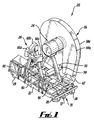
- the apparatus 20 includes a vehicle 22 in the form of a portable trolley which is moveable along rails relative to a structure to be measured.
- the apparatus 20 further includes structure illumination means 24 for illuminating a region of the structure being measured and image capturing means 26 for capturing an image of the region of the structure illuminated by the structure illumination means 24.
- the apparatus 20 is particularly suited for use in environments where access may be limited, for example on an underground rail network, and thus the structure illumination means 24 and the image capturing means 26 are removably mountable on the vehicle 22 in such a manner that accurate and repeatable repositioning of the structure illumination means 24 and the image capturing means 26 on the vehicle 22 can be achieved.
- the vehicle 22 is in the form of a lightweight trolley comprising four wheels 28 each having a profile suitable for running along rail tracks (not shown).
- the trolley 22 includes a fail safe braking mechanism which is known in the art and has a low height to enable it to be used in confined spaces, such as tunnels of an underground rail network.
- the vehicle 22 is portable and is sufficiently lightweight so that it can be carried by two persons and easily manoeuvred on and off rail tracks.
- the spacing between each pair of wheels 28 on opposite sides of the vehicle 22 is fixed so that the vehicle 22 is only able to run on rails having a fixed distance therebetween, this distance commonly being referred to as rail gauge. It is however common for rail gauges to vary, for example between 1050 millimetres to 1650 millimetres. Therefore, in order to obviate the need to provide different trolleys for different rail gauges, it is envisaged that means can be provided to vary the spacing between each pair of wheels 28 so that the trolley may easily be adapted to run along rails of varying gauge.
- the vehicle 22 is manually propelled and is pushed along rails to move the vehicle 22 relative to a structure. If desired, the vehicle 22 can be coupled to a further vehicle (not shown) adapted to tow the vehicle 22 and move it along rails relative to a structure. In an alternative embodiment, the vehicle 22 may be provided with propulsion means, for example in the form of an electric motor, coupled to one or more of the wheels 28, or an additional wheel engaged with a rail, to propel the vehicle 22.
- propulsion means for example in the form of an electric motor, coupled to one or more of the wheels 28, or an additional wheel engaged with a rail, to propel the vehicle 22.
- the structure illumination means 24 is intended to illuminate a region of a structure to be measured using the apparatus 20.
- the structure illumination means 24 comprises an array of six circumferentially equispaced lasers 30 which are mounted so that they each project a laser beam in use generally horizontally and in a forwards direction in the direction of travel of the vehicle 22.
- the lasers 30 together provide a sufficient level of illumination of a structure so that the image capturing means 26 can capture images of the structure.
- the lasers 30 are mounted within a housing 32 in the form of a cylindrical drum.
- the housing 32 comprises a first portion 34 and a second portion 36 which may be separated at interface 38 to reduce the weight of the housing 32 for handling purposes.
- the housing 32 comprises aluminium shrouded in rubber so that the lasers 30 are protected against damage in the event of any impact of the housing 32, which could for example occur if the housing 32 is dropped. It will of course be appreciated that any suitable impact resistant material, such as a lightweight composite material, may be used to fabricate the housing.
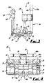
- the structure illumination means 24 therefore further comprises a deflector arrangement 40 which deflects the beams of laser light emitted by each of the lasers 30 in a plane perpendicular to the direction of orientation of the lasers 30.
- the deflector arrangement 40 thus causes the light emitted by the lasers 30 to be deflected towards a structure and thereby illuminate that structure.
- the deflector arrangement 40 comprises six deflectors 42 which are circumferentially equispaced and mounted on a flange 44 which is itself removably secured to the housing 32.
- a deflector 42 is associated with each of the lasers 30 and each deflector 42 is carefully positioned to be in line with an associated laser so that when a laser beam is emitted by a laser 30 it is transmitted towards its respective deflector 42.
- each deflector 42 is in the form of a conical mirror and comprises a spherical portion 48 and a conically shaped reflective surface 50. Due to the conical shape of the reflective surface 50, when a beam of light projected by a respective laser 30 is incident upon the reflective surface 50, it is reflected and scattered in a plane generally perpendicular to the direction in which the beam of light is emitted by each laser 30.
- the deflector arrangement 40 includes shielding means which are located in appropriate positions relative to each of the deflectors 42.
- the shielding means comprises a plurality of shields 46, each of which comprises material that absorbs laser light.
- the shields 46 are circumferentially spaced around the same axis as the lasers 30 and a shield 46 is located between adjacent lasers 30.
- the shields 46 thus prevent any unwanted interference between light scattered by the deflectors 42 and thereby ensure that the light emitted by each laser 30 and reflected and scattered by each of the deflectors 42 illuminates only a predetermined and defined region of a structure being measured. Hence, an even level of illumination is achieved.
- a further laser 54 is provided within a housing 56.
- the further laser 54 is arranged to emit a beam of light generally horizontally in the forwards direction of travel of the vehicle 22.
- the housing 56 includes an opening 58, and a deflector (not shown) is located inside the housing so that the beam of light emitted by the laser 54 is scattered and reflected out of the housing through the opening 58.
- the light reflected through the opening 58 thus illuminates each of the rails so that images of the rails can be captured. This is important to provide reference points for measurements carried out using the apparatus 20.
- the image capturing means 26 comprises three battery powered measurement cameras 60a to 60c. Each of the cameras 60a to 60c is orientated so that it points in a different direction and can therefore capture an image of a different region of a structure. Three cameras 60a to 60c are provided so that when the apparatus 20 is located in a fully enclosed structure, such as a tunnel, the two cameras 60a, 60c capture images of the illuminated side regions of the structure, for example the tunnel walls, and the camera 60b captures an image of the top region of the structure, such as the tunnel roof. Thus, the separate images captured by each of the cameras 60a to 60c represent an image of the entire region of a structure illuminated by the structure illumination means 24.
- further cameras 62, 64 are removably mountable on the vehicle 22, and when mounted for use are orientated so that they each capture an image of one of the rails illuminated by the beam of light emitted through the opening 58 by the further laser 54.
- a further camera or cameras are provided on the vehicle 22 to continuously capture visual images of the structure being measured as the vehicle 22 is being moved. This allows a permanent visual record of the measurement operation to be retained and referred to when necessary.
- the measurement apparatus 20 includes a laser shield 66.
- the laser shield 66 comprises first and second plates 68a, 68b which are spaced apart and through which light emitted by the lasers cannot pass.
- the laser shield 66 is located on the apparatus 22 in a position to allow the light deflected and scattered by each of the deflectors 42 to exit the gap around the edge of the plates 68a, 68b and thereby illuminate an adjacent structure.
- the light is constrained in a plane defined by the spaced plates 68a, 68b, and a person standing at the rear of the vehicle 22 and pushing it along is thus shielded from direct laser exposure.
- the measurement apparatus 20 includes distance measurement means 70, best seen in Figs. 8 to 10.
- the distance measurement means 70 comprises a rotatable member in the form of a wheel 72 which is engageable with a surface of a rail track along which the vehicle 22 moves.
- the wheel 72 is rotatably supported in a mounting 74 which is pivotally attached at pivot 76 to a mounting plate 78 which includes brackets 80 for securing the distance measurement means 70 to the vehicle 22.
- the mounting 74 upon which the wheel 72 is rotatably mounted is biased about the pivot 76 towards a rail.
- Biasing means in the form of a spring 82 acts between the mounting 74 and a lip 84 provided on an edge of the mounting plate 78 so that the mounting is urged away from the plate 78 about the pivot 76.
- the distance measurement means 70 includes a shaft encoder 86 for measuring the rotation of the wheel 72 as the vehicle 22 is moved along rails. Data from the shaft encoder 86 is transmitted to a processor which is able to determine the distance travelled by the vehicle 22 and to relate this to structural measurements based on images captured by the image capturing means 26, as will be described hereinafter.
- batteries 90 are mounted on the vehicle 22. Further, in order to enable control of the apparatus and processing of images captured by the cameras 60a to 60c, 62, 64, a processor in the form of a computer 92 is provided on the vehicle 22.
- the computer 92 is provided with appropriate structural measurement software, and thus if desired, immediate on site structural analysis can be carried out using the measurement apparatus 20.
- the separate components namely the structure illumination means 24, the cameras 60a to 60c, 62 and 64, the batteries 90 and the computer 92 are transported to the location at which measurement is to take place.
- the vehicle 22 is also transported to the location and prior to commencing measurement, all of the aforesaid components of the apparatus 20 are mounted on the vehicle 22 so that the apparatus 20 is ready for use.
- the apparatus 20 is provided with releasable mountings which enable repeated mounting and removal of the components on the vehicle 22, and which provide for accurate and repeatable repositioning when remounted on the vehicle 22.
- the lasers 30, 54 and the cameras 60a to 60c, 62, 64 are all activated so that any structure adjacent the vehicle 22 is illuminated by the lasers 30 and the rails along which the vehicle 22 is moveable are also illuminated by the laser 54.
- the apparatus 22 is being used in a tunnel, a slice of the entire cross-section of the tunnel wall will be illuminated by the lasers 30 whose light is deflected and scattered by the deflectors 42, as hereinbefore described.
- the vehicle 22 is then manually pushed by a user standing behind the vehicle along rails so that the vehicle 22 is moved relative to an adjacent structure or structures, for example through a tunnel.
- the cameras 60a to 60c continuously capture images of a structure illuminated by the lasers 30. For example, as the vehicle 22 is pushed through a tunnel, the cameras 60a to 60c continuously capture cross-sectional images of the tunnel wall along the length of the tunnel.
- images are continuously captured by the cameras 60a to 60c, 62, 64 between pre-determined points along the rails.
- these pre-determined points may be spaced apart at intervals of five metres.
- the software used to carry out structural analysis using the images captured by the cameras produces a worst case two-dimensional cross-sectional profile between those pre-determined intervals.
- the cross-sectional profile will vary along the length of the tunnel between the pre-determined intervals.
- the software with which the captured images are analysed will produce a two-dimensional cross-sectional view of the tunnel which will be made up of those points along the length of the tunnel between the pre-determined intervals where there is least clearance between a reference point and the tunnel wall.
- the cameras 62, 64 In order to provide the reference point on which the structural measurements can be based using the images captured by the cameras 60a to 60c, the cameras 62, 64 also continuously capture images of the rails illuminated by the laser 54 between the predetermined intervals as the vehicle 22 is moved along the rails. Images captured by the cameras 62, 64 are thus also utilised by the software when creating cross-sectional profiles.
- the distance measurement means 70 In order to enable the apparatus 20 to determine when the vehicle 22 has travelled a pre-determined distance between pre-determined intervals along the rails, the distance measurement means 70 also operates continuously to transmit distance measurement data to the computer 92 on board the vehicle 22.
- measurement apparatus 20 which, due to its modular design allowing removable attachment of all components, can be easily transported and therefore used to measure structures in locations where access is restricted, such as for example on an underground rail network.
- the use of conical mirrors in the deflector arrangement 40 enables a structure to be fully illuminated whilst using only a small number of lasers 30. This is particularly advantageous since power consumption is minimised and hence this provides added advantages in relation to the modularity and transportability of the apparatus 20.
- a further and particularly important advantage of the apparatus 20 relates to its ability to take continuous measurements of a structure as the vehicle 22 is moved continuously relative to a structure being measured. This provides for a very significant reduction in the time taken to measure a structure when compared to the time needed to measure the same structure using apparatus which does not operate in such a continuous manner.
- the vehicle 22 may be motorised and may include means for carrying an operator during movement of the vehicle along rails relative to a structure.
- the vehicle 22 may be of a different design provided that it allows for removable mounting of the various components thereon. Whilst the vehicle 22 has been illustrated for use on rails, the wheels 28 could be replaced with conventional wheels so that the vehicle 22 is able to run along any surface. Thus, the vehicle 22 could for example be used for measuring any structure.
- the support on which the structure illumination means 24 is mounted may provide for movement of the structure illumination means 24 relative to the vehicle 22, for example so that the height of the structure illumination means 24 may be varied.
- the apparatus 20 may include further measurement cameras to enable the measurement of larger structures.
Landscapes
- Engineering & Computer Science (AREA)
- Mechanical Engineering (AREA)
- Architecture (AREA)
- Civil Engineering (AREA)
- Structural Engineering (AREA)
- Length Measuring Devices By Optical Means (AREA)
- Investigating, Analyzing Materials By Fluorescence Or Luminescence (AREA)
Applications Claiming Priority (2)
| Application Number | Priority Date | Filing Date | Title |
|---|---|---|---|
| GB0405914A GB2412261A (en) | 2004-03-17 | 2004-03-17 | Apparatus for determining the profile of structures alongside railway tracks |
| GB0405914 | 2004-03-17 |
Publications (2)
| Publication Number | Publication Date |
|---|---|
| EP1577440A2 true EP1577440A2 (de) | 2005-09-21 |
| EP1577440A3 EP1577440A3 (de) | 2005-12-07 |
Family
ID=32117804
Family Applications (1)
| Application Number | Title | Priority Date | Filing Date |
|---|---|---|---|
| EP05251576A Withdrawn EP1577440A3 (de) | 2004-03-17 | 2005-03-16 | Messvorrichtung |
Country Status (2)
| Country | Link |
|---|---|
| EP (1) | EP1577440A3 (de) |
| GB (1) | GB2412261A (de) |
Cited By (1)
| Publication number | Priority date | Publication date | Assignee | Title |
|---|---|---|---|---|
| WO2013106534A1 (en) * | 2012-01-11 | 2013-07-18 | International Business Machines Corporation | System and method for inexpensive railroad track imaging for inspection |
Families Citing this family (2)
| Publication number | Priority date | Publication date | Assignee | Title |
|---|---|---|---|---|
| GB2428724A (en) | 2005-07-29 | 2007-02-07 | Laser Rail Ltd | A datum monument |
| ES2369185B1 (es) * | 2010-04-16 | 2012-10-11 | Euroconsult Nuevas Tecnologias, S.A. | Sistema para la auscultación dinámica de revestimientos de túneles. |
Family Cites Families (13)
| Publication number | Priority date | Publication date | Assignee | Title |
|---|---|---|---|---|
| US4065856A (en) * | 1973-05-23 | 1978-01-03 | British Railways Board | Maintenance machines for railway track |
| US4063283A (en) * | 1975-04-03 | 1977-12-13 | Chemetron Corporation | Automatic envelope measuring system |
| AT353487B (de) * | 1977-05-31 | 1979-11-12 | Plasser Bahnbaumasch Franz | Vermessungseinrichtung zur anzeige bzw. registrierung des profilverlaufes von tunnel- roehren, durchlaessen u.dgl. engstellen |
| US5212655A (en) * | 1990-11-21 | 1993-05-18 | Csx Transporation, Inc. | Clearance measurement system, video clearance measurement vehicle and improved method of performing clearance measurements |
| DE4238034C1 (de) * | 1992-11-11 | 1994-03-31 | Michael Dipl Ing Sartori | Verfahren und Vorrichtung zum inspektierenden, berührungslosen Abtasten der unmittelbaren Umgebung einer Gleisstrecke hinsichtlich bestimmter Meßkriterien |
| JPH0850317A (ja) * | 1994-08-05 | 1996-02-20 | Toyo Consultant Kk | 遠隔撮影装置 |
| DE19510560A1 (de) * | 1995-03-23 | 1996-09-26 | Misoph Rotraud | Meßvorrichtung zur berührungsfreien Vermessung des Schienenprofils |
| FR2739182B1 (fr) * | 1995-09-25 | 1997-12-19 | Drouard | Dispositif de controle de la position d'une voie ferree par rapport a un trace de reference |
| US6064428A (en) * | 1996-08-05 | 2000-05-16 | National Railroad Passenger Corporation | Automated track inspection vehicle and method |
| DE19801311A1 (de) * | 1997-10-30 | 1999-05-06 | Gsg Knape Gleissanierung Gmbh | Schienengebundene Instandhaltungsmaschine |
| GB2372315A (en) * | 2001-02-20 | 2002-08-21 | Digital Image Res Ltd | Determining the track condition in a transport system |
| JP2002256565A (ja) * | 2001-02-28 | 2002-09-11 | National House Industrial Co Ltd | 床下の点検作業車及びそれを用いた床下の点検方法 |
| US7755660B2 (en) * | 2003-05-02 | 2010-07-13 | Ensco, Inc. | Video inspection system for inspection of rail components and method thereof |
-
2004
- 2004-03-17 GB GB0405914A patent/GB2412261A/en not_active Withdrawn
-
2005
- 2005-03-16 EP EP05251576A patent/EP1577440A3/de not_active Withdrawn
Cited By (2)
| Publication number | Priority date | Publication date | Assignee | Title |
|---|---|---|---|---|
| WO2013106534A1 (en) * | 2012-01-11 | 2013-07-18 | International Business Machines Corporation | System and method for inexpensive railroad track imaging for inspection |
| US9036025B2 (en) | 2012-01-11 | 2015-05-19 | International Business Macines Corporation | System and method for inexpensive railroad track imaging for inspection |
Also Published As
| Publication number | Publication date |
|---|---|
| EP1577440A3 (de) | 2005-12-07 |
| GB2412261A (en) | 2005-09-21 |
| GB0405914D0 (en) | 2004-04-21 |
Similar Documents
| Publication | Publication Date | Title |
|---|---|---|
| ES2818654T3 (es) | Procedimiento y sistemas pasivos y activos combinados para detectar y medir fallas internas dentro de raíles metálicos | |
| CN111366082B (zh) | 移动式接触轨检测装置及其应用方法 | |
| US20020166248A1 (en) | Method and apparatus for track geometry measurement | |
| US7483510B2 (en) | Relocatable X-ray imaging system and method for inspecting commercial vehicles and cargo containers | |
| US10384697B2 (en) | Protective shroud for enveloping light from a light emitter for mapping of a railway track | |
| RU2251683C2 (ru) | Устройство для осмотра контейнеров | |
| US7659972B2 (en) | Rail measurement system | |
| CA2760365C (en) | Rapid assembly and operation of an x-ray imaging system | |
| EP1236634A1 (de) | Verfahren und Vorrichtung zur Feststellung des Zustandes eines Gleises | |
| GB2388661A (en) | Railway surveying | |
| EP1434029A3 (de) | Positionsmesseinrichtung mit einem rotierenden Lasergerät | |
| CN107576991B (zh) | 车辆检测系统 | |
| EP1577440A2 (de) | Messvorrichtung | |
| EP1324005A3 (de) | Vorrichtung und Verfahren zur Messung der Unrundheit, Schwankung, Ebenen und Rollparametern von Eisenbahnrädern | |
| US20090323082A1 (en) | Optical Profile Scanning | |
| CN211504015U (zh) | 移动式接触轨检测装置 | |
| CN210570537U (zh) | 弓网接触线磨耗在线检测装置 | |
| JP4041566B2 (ja) | 軌道検査装置 | |
| CN117191833A (zh) | 对象扫描装置 | |
| ES2228364T3 (es) | Sistema de toma y de evaluacion de imagenes. | |
| JP3980022B2 (ja) | 車輪測定装置 | |
| JPH11142124A (ja) | レ−ルの断面形状測定方法及び装置 | |
| JP7030306B2 (ja) | 矢印板自動設置・回収装置および矢印板の設置回収方法 | |
| CN117026801B (zh) | 一种检测斜拉索缆的机器人 | |
| US20250319913A1 (en) | Undercarriage inspection assemblies and systems |
Legal Events
| Date | Code | Title | Description |
|---|---|---|---|
| PUAI | Public reference made under article 153(3) epc to a published international application that has entered the european phase |
Free format text: ORIGINAL CODE: 0009012 |
|
| AK | Designated contracting states |
Kind code of ref document: A2 Designated state(s): AT BE BG CH CY CZ DE DK EE ES FI FR GB GR HU IE IS IT LI LT LU MC NL PL PT RO SE SI SK TR |
|
| AX | Request for extension of the european patent |
Extension state: AL BA HR LV MK YU |
|
| PUAL | Search report despatched |
Free format text: ORIGINAL CODE: 0009013 |
|
| AK | Designated contracting states |
Kind code of ref document: A3 Designated state(s): AT BE BG CH CY CZ DE DK EE ES FI FR GB GR HU IE IS IT LI LT LU MC NL PL PT RO SE SI SK TR |
|
| AX | Request for extension of the european patent |
Extension state: AL BA HR LV MK YU |
|
| 17P | Request for examination filed |
Effective date: 20060307 |
|
| AKX | Designation fees paid |
Designated state(s): AT BE BG CH CY CZ DE DK EE ES FI FR GB GR HU IE IS IT LI LT LU MC NL PL PT RO SE SI SK TR |
|
| 17Q | First examination report despatched |
Effective date: 20070215 |
|
| STAA | Information on the status of an ep patent application or granted ep patent |
Free format text: STATUS: THE APPLICATION IS DEEMED TO BE WITHDRAWN |
|
| 18D | Application deemed to be withdrawn |
Effective date: 20070625 |