EP1577258A1 - Filling head and cleaning apparatus therefor - Google Patents
Filling head and cleaning apparatus therefor Download PDFInfo
- Publication number
- EP1577258A1 EP1577258A1 EP05101290A EP05101290A EP1577258A1 EP 1577258 A1 EP1577258 A1 EP 1577258A1 EP 05101290 A EP05101290 A EP 05101290A EP 05101290 A EP05101290 A EP 05101290A EP 1577258 A1 EP1577258 A1 EP 1577258A1
- Authority
- EP
- European Patent Office
- Prior art keywords
- filling
- bottle
- dummy
- dummy bottle
- nozzle
- Prior art date
- Legal status (The legal status is an assumption and is not a legal conclusion. Google has not performed a legal analysis and makes no representation as to the accuracy of the status listed.)
- Withdrawn
Links
- 238000004140 cleaning Methods 0.000 title description 13
- 238000006073 displacement reaction Methods 0.000 claims abstract description 14
- 230000000284 resting effect Effects 0.000 claims abstract description 7
- 230000001360 synchronised effect Effects 0.000 claims abstract 2
- 238000011012 sanitization Methods 0.000 claims description 26
- 230000008878 coupling Effects 0.000 claims 1
- 238000010168 coupling process Methods 0.000 claims 1
- 238000005859 coupling reaction Methods 0.000 claims 1
- 238000000034 method Methods 0.000 description 21
- 230000008569 process Effects 0.000 description 15
- 235000013361 beverage Nutrition 0.000 description 13
- 238000010276 construction Methods 0.000 description 5
- 238000013519 translation Methods 0.000 description 5
- 239000010902 straw Substances 0.000 description 3
- 230000009471 action Effects 0.000 description 2
- 230000000721 bacterilogical effect Effects 0.000 description 2
- 230000000694 effects Effects 0.000 description 2
- 230000006872 improvement Effects 0.000 description 2
- 238000012546 transfer Methods 0.000 description 2
- XLYOFNOQVPJJNP-UHFFFAOYSA-N water Substances O XLYOFNOQVPJJNP-UHFFFAOYSA-N 0.000 description 2
- 241000282414 Homo sapiens Species 0.000 description 1
- CDBYLPFSWZWCQE-UHFFFAOYSA-L Sodium Carbonate Chemical compound [Na+].[Na+].[O-]C([O-])=O CDBYLPFSWZWCQE-UHFFFAOYSA-L 0.000 description 1
- 230000003749 cleanliness Effects 0.000 description 1
- 230000002860 competitive effect Effects 0.000 description 1
- 238000005202 decontamination Methods 0.000 description 1
- 230000003588 decontaminative effect Effects 0.000 description 1
- 230000000593 degrading effect Effects 0.000 description 1
- 239000000645 desinfectant Substances 0.000 description 1
- 230000008030 elimination Effects 0.000 description 1
- 238000003379 elimination reaction Methods 0.000 description 1
- 238000005429 filling process Methods 0.000 description 1
- 238000009432 framing Methods 0.000 description 1
- 230000005802 health problem Effects 0.000 description 1
- 230000000670 limiting effect Effects 0.000 description 1
- 239000007788 liquid Substances 0.000 description 1
- 230000007246 mechanism Effects 0.000 description 1
- 239000000203 mixture Substances 0.000 description 1
- 230000004048 modification Effects 0.000 description 1
- 238000012986 modification Methods 0.000 description 1
- 238000006386 neutralization reaction Methods 0.000 description 1
- 238000005086 pumping Methods 0.000 description 1
- 230000009467 reduction Effects 0.000 description 1
- 230000000717 retained effect Effects 0.000 description 1
- 230000002441 reversible effect Effects 0.000 description 1
- 239000008223 sterile water Substances 0.000 description 1
- 238000013022 venting Methods 0.000 description 1
Images



Classifications
-
- B—PERFORMING OPERATIONS; TRANSPORTING
- B67—OPENING, CLOSING OR CLEANING BOTTLES, JARS OR SIMILAR CONTAINERS; LIQUID HANDLING
- B67C—CLEANING, FILLING WITH LIQUIDS OR SEMILIQUIDS, OR EMPTYING, OF BOTTLES, JARS, CANS, CASKS, BARRELS, OR SIMILAR CONTAINERS, NOT OTHERWISE PROVIDED FOR; FUNNELS
- B67C3/00—Bottling liquids or semiliquids; Filling jars or cans with liquids or semiliquids using bottling or like apparatus; Filling casks or barrels with liquids or semiliquids
- B67C3/001—Cleaning of filling devices
- B67C3/002—Cleaning of filling devices using cups or dummies to be placed under the filling heads
- B67C3/004—Cleaning of filling devices using cups or dummies to be placed under the filling heads permanently attached to the filling machine and movable between a rest and a working position
Definitions
- the present invention refers to an improved kind of industrial bottle filling apparatus provided with filling valves of a particularly advanced type.
- filling plants generally require them to be allowed to periodically undergo a sanitization process, i.e. a hygienic-grade cleaning process involving all parts of a bottle filling plant or apparatus that are intended or designed to come into contact with the beverage to be bottled; in particular, the parts requiring periodical sanitizing include all beverage-carrying conduits, filling nozzles, pumps, and the like.
- a sanitization process i.e. a hygienic-grade cleaning process involving all parts of a bottle filling plant or apparatus that are intended or designed to come into contact with the beverage to be bottled
- the parts requiring periodical sanitizing include all beverage-carrying conduits, filling nozzles, pumps, and the like.
- Such process has the purpose of ensuring a complete removal of all beverage residues that may have been retained within the apparatus and be kept there during downtime periods so as to give rise to health problems due to the stagnation thereof, as well as sanitizing the apparatus itself for any other reason whatsoever.
- This sanitizing process is usually carried out by causing a flow of cleaning liquor to forcibly flow through the conduits and over the parts that are generally in contact with the beverage to be bottled, wherein such liquor may be of a different nature, depending on the cleaning action being required, and usually consists of a mixture of water and soda, or sterile water containing various kinds of disinfectants, which is pumped into the circuit to be sanitized according to strictly established procedures.
- a special container also called dummy bottle in the current technical parlance
- the purpose of this dummy bottle is to collect the sanitizing or cleaning liquor flowing out of the nozzle and, as a result, to simulate a regular bottle, thereby enabling the various phases of a regular filling process to be carried out and, hence, the various parts of the filling apparatus to be put to work regularly.
- human beings are bacteriologically infected and, therefore, by introducing a person to place and remove dummy bottles in the environment containing the bottling plant, the risk is run of degrading the level of bacteriological decontamination of such environment down to a point at which it may no longer prove acceptable, with easily imaginable consequences from an industrial point of view.
- EP 0597161 Known from the disclosure in EP 0597161 is a bottle filling apparatus intended particularly for wine bottling applications.
- This apparatus uses a neutralization of the atmosphere within the bottle prior to bottling, using a cleansing gas to that purpose.
- This solution is far from being acceptable or effective when there is a need for the whole bottle filling plant to be caused to undergo intensive sanitizing.
- EP 0568121 Known from the disclosure in EP 0568121 is an apparatus for sanitizing beverage bottling plants; such apparatus, however, turns out as being really bulky, excessively dedicated to sanitizing the sole beverage reservoir, and scarcely adapted to handle high-output industrial bottling plants.
- the US patent No. 5,819,817 covers a sanitizing arrangement provided with a dummy bottle for the sanitizing process.
- This dummy bottle is transferred through a double translation and lowering/lifting displacement; these displacements imply an undesired construction complication.
- the arrangement has clear and definite limitations due to its bulkiness and related space requirements, especially as far as its side and horizontal conduit 5 and its horizontal translatory displacement are concerned.
- EP 0409798 Disclosed in EP 0409798 is a filling nozzle in a bottling plant, which is associated to a respective dummy bottle to sanitizing purposes.
- the displacement of the dummy bottle is performed through a threefold translation, i.e. a translation from the top down, a horizontal translation and, again, a translation upwards. It can be readily appreciated how even this solution necessarily implies considerable complications in both construction and operation of the whole arrangement.
- these positioning and withdrawing operations shall be capable of being performed in a very quick manner and, therefore, shall require direct, readily accomplished displacements, without any complicated and, hence, slow trajectory.
- the above-noted apparatus must be easily and readily implemented using existing or readily available means and techniques, and shall further be competitive in its construction; moreover, it shall not introduce or require any significant modification in the function, operation and construction of existing plants.
- an industrial beverage bottling apparatus of a traditional kind comprises a central structure, about which there is caused to rotate a carousel of filling nozzles 1 provided integral with each other and capable of being selectively connected to appropriate reservoirs and pumps adapted to contain and transfer, respectively, the beverage to be bottled.
- the bottles to be filled are conveyed in an orderly sequence below respective ones of said nozzles, which, again in an orderly sequence and using means and methods of various kind, but largely known as such in the art, ensuring a tight fit between the nozzle and the filling mouth of the respective bottle, let the beverage into the same bottle.
- the bottles to be filled with the beverage are replaced with respective dummy bottles 2, whose task is to act as a means for collecting the cleaning liquor that is pumped under pressure through the filling conduits and, most obviously, flows eventually out of the filling nozzles.
- the cleaning liquor is removed therefrom by letting it out through a so-called “straw" 3, which is simply a thin tube that is associated to a respective nozzle 1 and is inserted jointly therewith into the bottle during regular bottling operation; with the opposite end thereof, said straw, or thin tube, is so placed as to debouch into a tank 14 provided to collect and let off the exhausted cleaning liquor.
- straw is simply a thin tube that is associated to a respective nozzle 1 and is inserted jointly therewith into the bottle during regular bottling operation; with the opposite end thereof, said straw, or thin tube, is so placed as to debouch into a tank 14 provided to collect and let off the exhausted cleaning liquor.
- said thin tube fulfils the task of providing a vent passage for the air contained in the bottle to be able to escape therethrough when the beverage is being let into the same bottle and, by occupying the internal volume thereof, drives out the air contained therein.
- said thin tube is then used as an exhaust passage to let off the cleaning liquor used in the sanitizing operation and eventually collecting into the dummy bottle.
- each filling nozzle is provided with a respective dummy bottle 2 and respective general means adapted to selectively transfer said dummy bottle from a resting or inoperative position 2A to a working or operative position 2B exactly underneath the respective nozzle 1; the displacement motion performed by said means takes place along a trajectory having following characteristics:
- each such nozzle 1 said general means are constituted by:
- the above-mentioned support plate 4 is provided with a hole, in which there is inserted a axle 8 firmly joined to said sprocket wheel 5; said displacement arm 6 is in turn associated in a firmly joined manner with an end portion thereof to said axle 8, whereas with the other end portion thereof it is connected to the dummy bottle 2.
- the nozzle 1 in the first place, as a preparatory operation in view of the cleaning process, the nozzle 1 is slightly raised by an extent H (see Figure 5) so as to allow for the respective dummy bottle 2 to be able to be displaced exactly underneath the nozzle itself and into alignment therewith (said means for first raising and then lowering again the nozzle 1 are well known as such in the art and are of no relevance to the purposes of the present invention; therefore, any further description or illustration thereof is intentionally omitted).
- said sprocket wheel 5 is automatically rotated mechanically relative to the plate 4, whereby it is imparted - with means that shall be illustrated in greater detail further on - a rotary motion about its axle 8, so that the dummy bottle moves into position under the respective nozzle 1.
- the actual cleaning process may be started and carried out by pumping the various cleaning and sanitizing liquors into the conduits in accordance with the pre-set procedure.
- these liquors reach the nozzle 1, from where they flow out into the dummy bottle 2.
- a further outlet tube 11 which enables the interior of the same dummy bottle to communicate with said collection and discharge tank 14.
- the purpose of this further outlet tube 11 lies in making it easier for sanitizing liquors to more effectively leave the dummy bottle 2, thereby boosting the action of the afore mentioned "straw" or thin tube 3 and, ultimately, accelerating the draining process itself.
- said thin tube 3 is normally sized to solely enable the air to escape from the interior of the bottle when a beverage is being filled thereinto, so that it usually has a rather small size, i.e.
- Said additional drain tube may be embodied in a number of ways; according to a first embodiment thereof, said drain tube may include a flexible tube, an end portion of which is applied to the respective dummy bottle, whereas the opposite end portion thereof it connects to a fitting 18 that is firmly joined to, i.e. part of the structure of the apparatus.
- drain tube An improved embodiment of such drain tube consists in making it in the form of a rigid conduit, as illustrated in Figure 8. Obviously, in this case the drain tube must keep both its shape and size unaltered and this is only possible if the same drain tube is firmly joined to said displacement arm 6 and the centre of rotation of the dummy bottle is at the same time the centre of rotation of the fitting which said drain tube 11 connects to with an end portion thereof.
- the rotary motion to the respective sprocket wheels 5 may be provided in a number of different manners, all of which lie fully within the abilities of those skilled in the art.
- an advantageous improvement is reached by providing a single cogwheel 15 in a co-planar arrangement relative to the common plane of said sprockets 5, and with its axis coinciding with the axis of rotation O of the carousel of the apparatus (see Figure 9) and, therefore, parallel to the axis Y of rotation of the axle 8, said cogwheel being further so arranged as to permanently engage the teeth of said sprockets 5 with its cogged rim.
- Said cogwheel may actually be provided integral with the apparatus and is adapted to be driven to rotate by any desired angle at any desired moment using means that are largely known as such in the art. This enables said cogwheel to be operated in the desired manner in accordance with the sanitizing process to be carried out, so as to ensure the sprockets being rotated and, as a result, the dummy bottles being displaced and brought under the respective nozzles accordingly.
Landscapes
- Filling Of Jars Or Cans And Processes For Cleaning And Sealing Jars (AREA)
Abstract
Description
- The present invention refers to an improved kind of industrial bottle filling apparatus provided with filling valves of a particularly advanced type.
- Widely known in the art is the fact that filling plants generally require them to be allowed to periodically undergo a sanitization process, i.e. a hygienic-grade cleaning process involving all parts of a bottle filling plant or apparatus that are intended or designed to come into contact with the beverage to be bottled; in particular, the parts requiring periodical sanitizing include all beverage-carrying conduits, filling nozzles, pumps, and the like.
- Such process has the purpose of ensuring a complete removal of all beverage residues that may have been retained within the apparatus and be kept there during downtime periods so as to give rise to health problems due to the stagnation thereof, as well as sanitizing the apparatus itself for any other reason whatsoever.
- This sanitizing process is usually carried out by causing a flow of cleaning liquor to forcibly flow through the conduits and over the parts that are generally in contact with the beverage to be bottled, wherein such liquor may be of a different nature, depending on the cleaning action being required, and usually consists of a mixture of water and soda, or sterile water containing various kinds of disinfectants, which is pumped into the circuit to be sanitized according to strictly established procedures.
- Also widely known in the art is the fact that, for this sanitizing process to be carried out, a special container, also called dummy bottle in the current technical parlance, is arranged downstream of the filling nozzle. The purpose of this dummy bottle is to collect the sanitizing or cleaning liquor flowing out of the nozzle and, as a result, to simulate a regular bottle, thereby enabling the various phases of a regular filling process to be carried out and, hence, the various parts of the filling apparatus to be put to work regularly.
- This process and the peculiarities thereof are well known to all those skilled in the art, so that they shall not be described any further in this context, where they are just hinted at so as to more clearly and accurately define the general framing in which the present invention is actually set.
- In particular, it is a largely known fact that dummy bottles are associated to the respective nozzles either manually or mechanically; in the first case, well-known drawbacks typically arise from the fact that each sanitizing procedure ultimately requires a lot of time for the dummy bottles to be placed and removed and this involves additional costs owing to both the operation of the plant having to be interrupted from time to time (downtime) and the direct costs involved in having to use skilled personnel in the process itself. In addition, even the effects of a process carried out manually in a beverage bottling environment must be duly taken into account. In fact, the applying law provisions call for these environments to be constantly kept in a clean state under controlled bacteriological conditions. Now, human beings are bacteriologically infected and, therefore, by introducing a person to place and remove dummy bottles in the environment containing the bottling plant, the risk is run of degrading the level of bacteriological decontamination of such environment down to a point at which it may no longer prove acceptable, with easily imaginable consequences from an industrial point of view.
- Known from the disclosure in DE 37 22 495 is a way of providing a bottle filling apparatus in which the dummy bottle is conveyed below the respective filling nozzle through a rotation about a horizontal axis; this solution, however, is not generally acceptable, since the dummy bottle, in certain positions thereof, causes part of the sanitizing liquor to drip therefrom, thereby impairing the cleanliness of the apparatus.
- Known from the disclosure in EP 0597161 is a bottle filling apparatus intended particularly for wine bottling applications. This apparatus uses a neutralization of the atmosphere within the bottle prior to bottling, using a cleansing gas to that purpose. This solution, however, is far from being acceptable or effective when there is a need for the whole bottle filling plant to be caused to undergo intensive sanitizing.
- Known from the disclosure in EP 0568121 is an apparatus for sanitizing beverage bottling plants; such apparatus, however, turns out as being really bulky, excessively dedicated to sanitizing the sole beverage reservoir, and scarcely adapted to handle high-output industrial bottling plants.
- The US patent No. 5,819,817 covers a sanitizing arrangement provided with a dummy bottle for the sanitizing process. This dummy bottle, however, is transferred through a double translation and lowering/lifting displacement; these displacements imply an undesired construction complication. In addition, the arrangement has clear and definite limitations due to its bulkiness and related space requirements, especially as far as its side and
horizontal conduit 5 and its horizontal translatory displacement are concerned. - Disclosed in EP 0409798 is a filling nozzle in a bottling plant, which is associated to a respective dummy bottle to sanitizing purposes. However, even in this case the displacement of the dummy bottle is performed through a threefold translation, i.e. a translation from the top down, a horizontal translation and, again, a translation upwards. It can be readily appreciated how even this solution necessarily implies considerable complications in both construction and operation of the whole arrangement.
- It would therefore be desirable, and is actually an object of the present invention, to provide an industrial beverage bottling apparatus, along with the related dummy bottles for sanitizing purposes, which are effective in doing away with the afore-indicated drawbacks and disadvantages and, in particular, in enabling each such dummy bottle to be positioned in a fully automatic manner relative to the corresponding filling nozzle prior to starting a sanitizing process, and to be retracted - again in a fully automatic manner - into a resting position upon completion of the plant sanitizing process.
- Furthermore, these positioning and withdrawing operations shall be capable of being performed in a very quick manner and, therefore, shall require direct, readily accomplished displacements, without any complicated and, hence, slow trajectory.
- According to another purpose of the present invention, the above-noted apparatus must be easily and readily implemented using existing or readily available means and techniques, and shall further be competitive in its construction; moreover, it shall not introduce or require any significant modification in the function, operation and construction of existing plants.
- According to the present invention, these aims are reached in a particular kind of apparatus, and related dummy bottles, provided with operating means as described below by way of non-limiting example with reference to the accompanying drawings, in which:
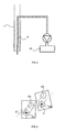
- Figure 1 is a simplified outside view of an improved bottle filling apparatus according to the present invention;
- Figure 2 is a symbolical front and vertical sectional view of some parts of an apparatus according to the present invention;
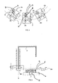
- Figure 3 is a top view of a symbolical, simplified representation of the working and resting positions of the dummy bottles in an apparatus according to the present invention;
- Figure 4 is a top view of a simplified representation of a filling valve provided with the displacement and positioning members for a dummy bottle according to the present invention;
- Figure 5 is a projection on a vertical plane of the valve shown in Figure 4;
- Figure 6 is a symbolical top view of an improved embodiment of the present invention;
- Figure 7 is a view of an ameliorative variant of the improved embodiment shown in Figure 6;
- Figure 8 is a perspective bottom view of a valve according to the present invention, in a preferred embodiment thereof;
- Figure 9 is a schematical top view of a preferred embodiment of the displacement and positioning members for the dummy bottles in an apparatus according to the present invention.
- With reference to the above-cited Figures, in particular Figures 1 and 2, an industrial beverage bottling apparatus of a traditional kind comprises a central structure, about which there is caused to rotate a carousel of filling
nozzles 1 provided integral with each other and capable of being selectively connected to appropriate reservoirs and pumps adapted to contain and transfer, respectively, the beverage to be bottled. The bottles to be filled are conveyed in an orderly sequence below respective ones of said nozzles, which, again in an orderly sequence and using means and methods of various kind, but largely known as such in the art, ensuring a tight fit between the nozzle and the filling mouth of the respective bottle, let the beverage into the same bottle. - When the need arises for the bottling plant to undergo sanitization, the bottles to be filled with the beverage are replaced with respective
dummy bottles 2, whose task is to act as a means for collecting the cleaning liquor that is pumped under pressure through the filling conduits and, most obviously, flows eventually out of the filling nozzles. - Once let into the dummy bottle, the cleaning liquor is removed therefrom by letting it out through a so-called "straw" 3, which is simply a thin tube that is associated to a
respective nozzle 1 and is inserted jointly therewith into the bottle during regular bottling operation; with the opposite end thereof, said straw, or thin tube, is so placed as to debouch into a tank 14 provided to collect and let off the exhausted cleaning liquor. - In normal operation, said thin tube fulfils the task of providing a vent passage for the air contained in the bottle to be able to escape therethrough when the beverage is being let into the same bottle and, by occupying the internal volume thereof, drives out the air contained therein.
- When the plant is being sanitized, said thin tube is then used as an exhaust passage to let off the cleaning liquor used in the sanitizing operation and eventually collecting into the dummy bottle.
- In a bottle filling apparatus according to the present invention, and with reference to Figures 3 and 4, each filling nozzle is provided with a respective
dummy bottle 2 and respective general means adapted to selectively transfer said dummy bottle from a resting orinoperative position 2A to a working oroperative position 2B exactly underneath therespective nozzle 1; the displacement motion performed by said means takes place along a trajectory having following characteristics: - it lies solely on a horizontal plane, and
- it is formed in the shape of an arc of a circle.
- With particular reference to Figure 4, for each
such nozzle 1 said general means are constituted by: - a
support plate 4 integral or firmly joined with the main structure of the apparatus, - a
sprocket wheel 5, - a
displacement arm 6 carrying the respectivedummy bottle 2. - The above-mentioned
support plate 4 is provided with a hole, in which there is inserted aaxle 8 firmly joined to saidsprocket wheel 5; saiddisplacement arm 6 is in turn associated in a firmly joined manner with an end portion thereof to saidaxle 8, whereas with the other end portion thereof it is connected to thedummy bottle 2. All above-described members and parts are so sized and mutually arranged as to ensure that the axis X of thenozzle 1 is parallel to the axis Y of rotation of said rotatingaxle 8, so that the dummy bottle is displaced on a plane lying orthogonal to the axis of the filling carousel, which in turn coincides with said axis X, and sad sprocket wheel can take a position in which said displacement arm causes thedummy bottle 2 to move exactly beneath therespective nozzle 1 in a perfect alignment therewith, as this is illustrated in Figure 4. - The way in which the present invention works is rather simple: in the first place, as a preparatory operation in view of the cleaning process, the
nozzle 1 is slightly raised by an extent H (see Figure 5) so as to allow for the respectivedummy bottle 2 to be able to be displaced exactly underneath the nozzle itself and into alignment therewith (said means for first raising and then lowering again thenozzle 1 are well known as such in the art and are of no relevance to the purposes of the present invention; therefore, any further description or illustration thereof is intentionally omitted). - Thereafter, said
sprocket wheel 5 is automatically rotated mechanically relative to theplate 4, whereby it is imparted - with means that shall be illustrated in greater detail further on - a rotary motion about itsaxle 8, so that the dummy bottle moves into position under therespective nozzle 1. At this point, the actual cleaning process may be started and carried out by pumping the various cleaning and sanitizing liquors into the conduits in accordance with the pre-set procedure. Eventually, these liquors reach thenozzle 1, from where they flow out into thedummy bottle 2. From thedummy bottle 2, and by means of the above-mentionedthin tube 3, they are then let off, possibly under some suction effect of a pump or the like, into the 14 provided to collect and let off the exhausted cleaning liquor. - The procedure to be followed in order to restore the operative state of the apparatus and make it ready to start a new bottle filling sequence is then completed by going through the same steps as described above, but in the reverse order thereof.
- Fully apparent from the above description is therefore the ability of the the present invention to effectively reach the afore cited aims and advantages: in fact, by fully automating the operation required to bring the dummy bottle into position under the respective nozzle, considerable economic advantages are obtained through a reduction in apparatus downtime and the elimination of any labour connected with displacing and positioning the dummy bottle by hand; furthermore, the utmost simplicity of the parts and mechanisms involved and the easy, smooth way in which the dummy bottle is displaced through a single rotary motion requiring a single rotating drive member (i.e. the
sprocket wheel 5 in the particular case considered here) and arelated axle 8, make the invention particularly advantageous, effective and reliable. - Still a number of advantageous improvements are however possible: with reference to Figure 6, in the
outer wall 10 of the dummy bottle there is provided afurther outlet tube 11 which enables the interior of the same dummy bottle to communicate with said collection and discharge tank 14. The purpose of thisfurther outlet tube 11 lies in making it easier for sanitizing liquors to more effectively leave thedummy bottle 2, thereby boosting the action of the afore mentioned "straw" orthin tube 3 and, ultimately, accelerating the draining process itself. In this connection it should be noticed - and duly taken into account - that saidthin tube 3 is normally sized to solely enable the air to escape from the interior of the bottle when a beverage is being filled thereinto, so that it usually has a rather small size, i.e. diameter, on account of both the fact that a gas (i.e. air) requires venting conduits having much smaller diameters than the diameters that would on the contrary be required - under generally equal conditions - to let out an equal volume of liquid, and the fact that the diameter of thenozzle 1, which must contain saidthin tube 3, is anyway limited by the size of the filling mouth of the bottle. - Such a double draining arrangement therefore allows for a greater general hydraulic efficiency in the flow of the sanitizing liquors.
- Said additional drain tube may be embodied in a number of ways; according to a first embodiment thereof, said drain tube may include a flexible tube, an end portion of which is applied to the respective dummy bottle, whereas the opposite end portion thereof it connects to a fitting 18 that is firmly joined to, i.e. part of the structure of the apparatus.
- This construction, although quite simple and effective, has however a drawback in that the flexible tube is subject to quick wear-down; in addition, owing to the related attachment fitting on the apparatus having to be situated on the side where the dummy bottle comes to lie when moved into its resting or inoperative position, the length of said flexible drain tube becomes quite significant, so that space problems may well arise in view of being able to appropriately and conveniently accommodate such a flexible drain tube.
- An improved embodiment of such drain tube consists in making it in the form of a rigid conduit, as illustrated in Figure 8. Obviously, in this case the drain tube must keep both its shape and size unaltered and this is only possible if the same drain tube is firmly joined to said
displacement arm 6 and the centre of rotation of the dummy bottle is at the same time the centre of rotation of the fitting which saiddrain tube 11 connects to with an end portion thereof. - This requirement is complied with by providing a drain tube that uses a
rigid conduit 12, which connects with an end portion thereof to arotating fitting 13, wherein the latter must furthermore lie with its centre of rotation exactly aligned on the same axis Y of rotation of said axle, so that - as illustrated symbolically in Figures 7 and 8 - the assembly formed by rating fitting 13,rigid conduit 12 anddummy bottle 2 is an integral assembly firmly joined together. - Referring further to Figures 1, 8 and 9, the rotary motion to the
respective sprocket wheels 5 may be provided in a number of different manners, all of which lie fully within the abilities of those skilled in the art. Anyway, an advantageous improvement is reached by providing asingle cogwheel 15 in a co-planar arrangement relative to the common plane of saidsprockets 5, and with its axis coinciding with the axis of rotation O of the carousel of the apparatus (see Figure 9) and, therefore, parallel to the axis Y of rotation of theaxle 8, said cogwheel being further so arranged as to permanently engage the teeth of saidsprockets 5 with its cogged rim. - Said cogwheel may actually be provided integral with the apparatus and is adapted to be driven to rotate by any desired angle at any desired moment using means that are largely known as such in the art. This enables said cogwheel to be operated in the desired manner in accordance with the sanitizing process to be carried out, so as to ensure the sprockets being rotated and, as a result, the dummy bottles being displaced and brought under the respective nozzles accordingly. Those skilled in the art will furthermore have not failed to remark the two basic, considerable advantages offered by this solution: in fact, the individual sprockets are in this case driven to rotate by means of a very simple, easily controllable member, and all sprockets are automatically and simultaneously driven to rotate by a same angle by actuating a single control that solely commands the rotation of said
single cogwheel 15.
Claims (9)
- Filling valve for a bottle filling apparatus having a plurality of filling valves, comprising:characterized in that said general means are adapted to displace said dummy bottle from a resting position (2A) thereof to said filling position (2B) through a solely rotary motion.a filling nozzle (1),a dummy bottle (2),general means adapted to selectively place the dummy bottle in the corresponding filling position (2B) under the respective filling nozzle,
- Filling valve according to claim 1, characterized in that said rotary motion occurs on a plane that is substantially orthogonal to the axis (X) of the respective filling nozzle.
- Filling valve according to any of the preceding claims, characterized in that it further comprises:a respective rotatably driving sprocket (5) pivoted (7, 8) so that the respective axis (Y) is parallel to the axis (X) of said respective nozzle (1),a displacement arm (6) performing said rotation and connecting said dummy bottle (2) to said respective sprocket (5).
- Filling valve according to any of the preceding claims, characterized in that it further comprises:a drain tube (11) connecting the internal volume of a respective dummy bottle to outside collecting and discharge means (14),coupling means adapted to enable said drain tube to be arranged and connected between the respective dummy bottle (2) and a position that is integral with the structure of said filling valve in both resting and filling positions (2A, 2B) of said dummy bottle.
- Filling valve according to claim 4, characterized in that said drain tube comprises a flexible conduit.
- Filling valve according to claim 4, characterized in that said drain tube is a rigid conduit (12) and is applied between the respective dummy bottle (2) and a respective rotating fitting (13) arranged in correspondence to the axis (Y) of the respective one of said sprockets (5).
- Apparatus for filling a sequence of bottles, provided with a plurality of filling valves according to any of the preceding claims 1 to 6, characterized in that it is provided with driving means adapted to cause said respective sprockets (5) to perform a rotary motion about their axes, said sprockets being driven by said driving means in a synchronous manner.
- Bottle filling apparatus according to claim 7, characterized in that said driving means comprise a cogwheel (15) provided with cogs adapted to simultaneously engage, i.e. mesh with the teeth of said sprockets (5).
- Bottle filling apparatus according to claim 8, characterized in that said cogwheel (15) is adapted to be rotated selectively with respect to the sanitizing and filling cycle, and that, by virtue of said rotation, said dummy bottles are simultaneously moved and placed under respective ones of said filling nozzles (1).
Applications Claiming Priority (2)
| Application Number | Priority Date | Filing Date | Title |
|---|---|---|---|
| ITPN20040021 ITPN20040021A1 (en) | 2004-03-19 | 2004-03-19 | "BOTTLE FILLING SYSTEM WITH PERFECTED FILLING VALVE" |
| ITPN20040021 | 2004-03-19 |
Publications (1)
| Publication Number | Publication Date |
|---|---|
| EP1577258A1 true EP1577258A1 (en) | 2005-09-21 |
Family
ID=34835608
Family Applications (1)
| Application Number | Title | Priority Date | Filing Date |
|---|---|---|---|
| EP05101290A Withdrawn EP1577258A1 (en) | 2004-03-19 | 2005-02-21 | Filling head and cleaning apparatus therefor |
Country Status (2)
| Country | Link |
|---|---|
| EP (1) | EP1577258A1 (en) |
| IT (1) | ITPN20040021A1 (en) |
Cited By (28)
| Publication number | Priority date | Publication date | Assignee | Title |
|---|---|---|---|---|
| ES2310086A1 (en) * | 2006-04-12 | 2008-12-16 | Antonio Gallardo Gonzaalez | Bottle filling machine (Machine-translation by Google Translate, not legally binding) |
| EP2110359A1 (en) * | 2008-04-15 | 2009-10-21 | RONCHI MARIO S.p A. | Automatic apparatus for flushing operating machines and machine equipped with said apparatus |
| ITTO20090531A1 (en) * | 2009-07-16 | 2011-01-17 | Gai S P A | DEVICE FOR THE STERILIZATION OF FILLING MACHINES AND FILLING MACHINE PROVIDED WITH THIS DEVICE |
| DE102010027623A1 (en) | 2010-07-19 | 2012-01-19 | Krones Aktiengesellschaft | Filling device for containers with cleaning system |
| US8435026B2 (en) | 2006-04-13 | 2013-05-07 | Amcor Limited | Liquid or hydraulic blow molding |
| WO2013026523A3 (en) * | 2011-08-23 | 2013-06-27 | Khs Gmbh | Filling machine and method for controlling a filling machine |
| US8573964B2 (en) | 2006-04-13 | 2013-11-05 | Amcor Limited | Liquid or hydraulic blow molding |
| US8684723B2 (en) | 2011-02-16 | 2014-04-01 | Amcor Limited | Blow nozzle to control liquid flow with pre-stretch rod assembly and metal seat seal pin |
| US8714963B2 (en) | 2007-12-06 | 2014-05-06 | Amcor Limited | Liquid or hydraulic blow molding |
| US8714964B2 (en) | 2010-10-15 | 2014-05-06 | Amcor Limited | Blow nozzle to control liquid flow with pre-stretch rod assembly |
| US8721315B2 (en) | 2010-09-13 | 2014-05-13 | Amcor Limited | Method of handling liquid to prevent machine contamination during filling |
| US8727758B2 (en) | 2011-02-15 | 2014-05-20 | Amcor Limited | Reverse stretch rod for machine hygiene and processing |
| US8740609B2 (en) | 2011-06-09 | 2014-06-03 | Amcor Limited | CSD cooling and pressurization to keep CO2 in solution during forming |
| WO2014086459A1 (en) * | 2012-12-04 | 2014-06-12 | Khs Gmbh | Filling machine |
| US8827688B2 (en) | 2011-12-21 | 2014-09-09 | Amcor Limited | Sealing system for molding machine |
| US8828308B2 (en) | 2010-09-13 | 2014-09-09 | Amcor Limited | Hydroblow preform design |
| US8834778B2 (en) | 2010-09-13 | 2014-09-16 | Amcor Limited | Mold delay for increased pressure for forming container |
| US8968636B2 (en) | 2010-10-15 | 2015-03-03 | Discma Ag | Stretch rod system for liquid or hydraulic blow molding |
| US9044887B2 (en) | 2011-05-27 | 2015-06-02 | Discma Ag | Method of forming a container |
| US9216537B2 (en) | 2011-06-09 | 2015-12-22 | Discma Ag | Compensation for hydrapak machine using isolator cylinder |
| US9221223B2 (en) | 2011-12-22 | 2015-12-29 | Discma Ag | Apparatus and method for controlling temperature gradient through wall thickness of container |
| US9254617B2 (en) | 2011-10-27 | 2016-02-09 | Discma Ag | Method and apparatus for forming and filling a container |
| US9314955B2 (en) | 2010-10-15 | 2016-04-19 | Discma Ag | Use of optimized piston member for generating peak liquid pressure |
| CN105502252A (en) * | 2015-12-31 | 2016-04-20 | 杭州中亚机械股份有限公司 | Straight type filling device |
| CN105540513A (en) * | 2015-12-31 | 2016-05-04 | 杭州中亚机械股份有限公司 | Linear filling device |
| US9802375B2 (en) | 2011-10-27 | 2017-10-31 | Discma Ag | Counter stretch connecting rod and positive fill level control rod |
| CN114307722A (en) * | 2021-11-24 | 2022-04-12 | 浙江青虹新材料有限公司 | Processing equipment and processing technology of composite bentonite wood preservative |
| CN115448238A (en) * | 2022-07-18 | 2022-12-09 | 江苏新美星包装机械股份有限公司 | Single-drive multi-false-cup device |
Citations (3)
| Publication number | Priority date | Publication date | Assignee | Title |
|---|---|---|---|---|
| EP0568121A1 (en) * | 1992-02-03 | 1993-11-03 | Shikoku Kakoki Co., Ltd. | Device for cleaning filling machine |
| EP0597161A1 (en) * | 1992-11-12 | 1994-05-18 | Paul Careme | Combined device for discharging liquid and cleaning apparatus thereof |
| EP0785134A2 (en) * | 1996-01-16 | 1997-07-23 | Gruppo Bertolaso S.p.A. | Method and apparatus for sanitizing filling machines and systems, particularly for food products |
-
2004
- 2004-03-19 IT ITPN20040021 patent/ITPN20040021A1/en unknown
-
2005
- 2005-02-21 EP EP05101290A patent/EP1577258A1/en not_active Withdrawn
Patent Citations (3)
| Publication number | Priority date | Publication date | Assignee | Title |
|---|---|---|---|---|
| EP0568121A1 (en) * | 1992-02-03 | 1993-11-03 | Shikoku Kakoki Co., Ltd. | Device for cleaning filling machine |
| EP0597161A1 (en) * | 1992-11-12 | 1994-05-18 | Paul Careme | Combined device for discharging liquid and cleaning apparatus thereof |
| EP0785134A2 (en) * | 1996-01-16 | 1997-07-23 | Gruppo Bertolaso S.p.A. | Method and apparatus for sanitizing filling machines and systems, particularly for food products |
Cited By (38)
| Publication number | Priority date | Publication date | Assignee | Title |
|---|---|---|---|---|
| ES2310086B1 (en) * | 2006-04-12 | 2009-11-10 | Antonio Gallardo Gonzalez | BOTTLE FILLING MACHINE. |
| ES2310086A1 (en) * | 2006-04-12 | 2008-12-16 | Antonio Gallardo Gonzaalez | Bottle filling machine (Machine-translation by Google Translate, not legally binding) |
| US8435026B2 (en) | 2006-04-13 | 2013-05-07 | Amcor Limited | Liquid or hydraulic blow molding |
| US8573964B2 (en) | 2006-04-13 | 2013-11-05 | Amcor Limited | Liquid or hydraulic blow molding |
| US8714963B2 (en) | 2007-12-06 | 2014-05-06 | Amcor Limited | Liquid or hydraulic blow molding |
| US8858214B2 (en) | 2007-12-06 | 2014-10-14 | Amcor Limited | Liquid or hydraulic blow molding |
| EP2110359A1 (en) * | 2008-04-15 | 2009-10-21 | RONCHI MARIO S.p A. | Automatic apparatus for flushing operating machines and machine equipped with said apparatus |
| CN101559912B (en) * | 2008-04-15 | 2013-08-07 | 龙基马里奥股份公司 | Automatic apparatus for flushing operating machines and machines equipped with the said apparatus |
| ITTO20090531A1 (en) * | 2009-07-16 | 2011-01-17 | Gai S P A | DEVICE FOR THE STERILIZATION OF FILLING MACHINES AND FILLING MACHINE PROVIDED WITH THIS DEVICE |
| DE102010027623A1 (en) | 2010-07-19 | 2012-01-19 | Krones Aktiengesellschaft | Filling device for containers with cleaning system |
| EP2409947A2 (en) | 2010-07-19 | 2012-01-25 | Krones AG | Filling device for containers with cleaning system |
| US8828308B2 (en) | 2010-09-13 | 2014-09-09 | Amcor Limited | Hydroblow preform design |
| US8834778B2 (en) | 2010-09-13 | 2014-09-16 | Amcor Limited | Mold delay for increased pressure for forming container |
| US8721315B2 (en) | 2010-09-13 | 2014-05-13 | Amcor Limited | Method of handling liquid to prevent machine contamination during filling |
| US9339968B2 (en) | 2010-10-15 | 2016-05-17 | Discma Ag | Method of forming a container and filling the container with a headspace |
| US9314955B2 (en) | 2010-10-15 | 2016-04-19 | Discma Ag | Use of optimized piston member for generating peak liquid pressure |
| US8968636B2 (en) | 2010-10-15 | 2015-03-03 | Discma Ag | Stretch rod system for liquid or hydraulic blow molding |
| US8714964B2 (en) | 2010-10-15 | 2014-05-06 | Amcor Limited | Blow nozzle to control liquid flow with pre-stretch rod assembly |
| US8727758B2 (en) | 2011-02-15 | 2014-05-20 | Amcor Limited | Reverse stretch rod for machine hygiene and processing |
| US8684723B2 (en) | 2011-02-16 | 2014-04-01 | Amcor Limited | Blow nozzle to control liquid flow with pre-stretch rod assembly and metal seat seal pin |
| US9044887B2 (en) | 2011-05-27 | 2015-06-02 | Discma Ag | Method of forming a container |
| US9216537B2 (en) | 2011-06-09 | 2015-12-22 | Discma Ag | Compensation for hydrapak machine using isolator cylinder |
| US8740609B2 (en) | 2011-06-09 | 2014-06-03 | Amcor Limited | CSD cooling and pressurization to keep CO2 in solution during forming |
| US9284173B2 (en) | 2011-08-23 | 2016-03-15 | Khs Gmbh | Filling machine and method for controlling a filling machine |
| WO2013026523A3 (en) * | 2011-08-23 | 2013-06-27 | Khs Gmbh | Filling machine and method for controlling a filling machine |
| US9669578B2 (en) | 2011-10-27 | 2017-06-06 | Discma Ag | Method and apparatus for forming and filling a container |
| US9254617B2 (en) | 2011-10-27 | 2016-02-09 | Discma Ag | Method and apparatus for forming and filling a container |
| US10220580B2 (en) | 2011-10-27 | 2019-03-05 | Discma Ag | Counter stretch connecting rod and positive fill level control rod |
| US9802375B2 (en) | 2011-10-27 | 2017-10-31 | Discma Ag | Counter stretch connecting rod and positive fill level control rod |
| US8827688B2 (en) | 2011-12-21 | 2014-09-09 | Amcor Limited | Sealing system for molding machine |
| US9221223B2 (en) | 2011-12-22 | 2015-12-29 | Discma Ag | Apparatus and method for controlling temperature gradient through wall thickness of container |
| US9790073B2 (en) | 2012-12-04 | 2017-10-17 | Khs Gmbh | Filling machine |
| WO2014086459A1 (en) * | 2012-12-04 | 2014-06-12 | Khs Gmbh | Filling machine |
| CN105540513A (en) * | 2015-12-31 | 2016-05-04 | 杭州中亚机械股份有限公司 | Linear filling device |
| CN105502252A (en) * | 2015-12-31 | 2016-04-20 | 杭州中亚机械股份有限公司 | Straight type filling device |
| CN114307722A (en) * | 2021-11-24 | 2022-04-12 | 浙江青虹新材料有限公司 | Processing equipment and processing technology of composite bentonite wood preservative |
| CN115448238A (en) * | 2022-07-18 | 2022-12-09 | 江苏新美星包装机械股份有限公司 | Single-drive multi-false-cup device |
| CN115448238B (en) * | 2022-07-18 | 2023-09-22 | 江苏新美星包装机械股份有限公司 | Single-drive multi-dummy cup device |
Also Published As
| Publication number | Publication date |
|---|---|
| ITPN20040021A1 (en) | 2004-06-19 |
Similar Documents
| Publication | Publication Date | Title |
|---|---|---|
| EP0758624B1 (en) | A continuous-cycle sterile bottling plant | |
| EP1885514B1 (en) | Washing machine for ampoules | |
| CN218982611U (en) | Cleaning device for medicine decocting container | |
| CN216403833U (en) | Canned beverage sterilizing device | |
| GB445249A (en) | Improvements in bottle cleaning machines | |
| CN115848738A (en) | U-shaped serial-type cleaning mechanism for barreled water filling machine | |
| EP0605911B1 (en) | Cleaning device for a milking plant | |
| CN206701866U (en) | A kind of medical stomach tube for internal medicine Quick cleaning device | |
| JPH10338296A (en) | Cleaning device of filling nozzle of liquid filling machine | |
| JPH0930597A (en) | Method and device for cleaning food changing valve | |
| KR100483240B1 (en) | The method and apparatus for auto-cleaning of garbage can | |
| CN112353976A (en) | A virus killing deactivation device for virus storage jar | |
| CN217148537U (en) | Vacuum nitrogen filling protection device for wine filling | |
| CN211169822U (en) | Disinfection device for body of diagnostic reagent bottle | |
| CN215287938U (en) | Automatic recovery unit of beverage filling machine overflow | |
| CN112891585B (en) | A medical medicine bottle sterilization and maintenance device | |
| CN213312017U (en) | Orthodontic equipment degassing unit | |
| CN211330649U (en) | Test tube cleaning clamping device for inspection | |
| CN215833721U (en) | Remove convenient optical glasses piece with wasing case | |
| CN115887712A (en) | Automatic disinfection and soaking barrel for medical bottle appliances | |
| CN210903450U (en) | Root canal therapy instrument for dentistry | |
| CN218317456U (en) | Full-automatic liquid medicine filling equipment | |
| CN112938733A (en) | Cleaning and sterilizing device for escalator | |
| JPH0894641A (en) | Cleaning device for dispensing nozzle in inspection apparatus of blood and the like | |
| CN219834854U (en) | Cabbage breeding equipment |
Legal Events
| Date | Code | Title | Description |
|---|---|---|---|
| PUAI | Public reference made under article 153(3) epc to a published international application that has entered the european phase |
Free format text: ORIGINAL CODE: 0009012 |
|
| AK | Designated contracting states |
Kind code of ref document: A1 Designated state(s): AT BE BG CH CY CZ DE DK EE ES FI FR GB GR HU IE IS IT LI LT LU MC NL PL PT RO SE SI SK TR |
|
| AX | Request for extension of the european patent |
Extension state: AL BA HR LV MK YU |
|
| 17P | Request for examination filed |
Effective date: 20060210 |
|
| AKX | Designation fees paid |
Designated state(s): AT BE BG CH CY CZ DE DK EE ES FI FR GB GR HU IE IS IT LI LT LU MC NL PL PT RO SE SI SK TR |
|
| 17Q | First examination report despatched |
Effective date: 20070202 |
|
| STAA | Information on the status of an ep patent application or granted ep patent |
Free format text: STATUS: THE APPLICATION IS DEEMED TO BE WITHDRAWN |
|
| 18D | Application deemed to be withdrawn |
Effective date: 20070613 |