EP1577206A2 - Front fork of two-wheeled vehicle or the like - Google Patents
Front fork of two-wheeled vehicle or the like Download PDFInfo
- Publication number
- EP1577206A2 EP1577206A2 EP04021389A EP04021389A EP1577206A2 EP 1577206 A2 EP1577206 A2 EP 1577206A2 EP 04021389 A EP04021389 A EP 04021389A EP 04021389 A EP04021389 A EP 04021389A EP 1577206 A2 EP1577206 A2 EP 1577206A2
- Authority
- EP
- European Patent Office
- Prior art keywords
- inner tube
- front fork
- oil
- gap
- end side
- Prior art date
- Legal status (The legal status is an assumption and is not a legal conclusion. Google has not performed a legal analysis and makes no representation as to the accuracy of the status listed.)
- Withdrawn
Links
Images


Classifications
-
- B—PERFORMING OPERATIONS; TRANSPORTING
- B62—LAND VEHICLES FOR TRAVELLING OTHERWISE THAN ON RAILS
- B62K—CYCLES; CYCLE FRAMES; CYCLE STEERING DEVICES; RIDER-OPERATED TERMINAL CONTROLS SPECIALLY ADAPTED FOR CYCLES; CYCLE AXLE SUSPENSIONS; CYCLE SIDECARS, FORECARS, OR THE LIKE
- B62K25/00—Axle suspensions
- B62K25/04—Axle suspensions for mounting axles resiliently on cycle frame or fork
- B62K25/06—Axle suspensions for mounting axles resiliently on cycle frame or fork with telescopic fork, e.g. including auxiliary rocking arms
- B62K25/08—Axle suspensions for mounting axles resiliently on cycle frame or fork with telescopic fork, e.g. including auxiliary rocking arms for front wheel
Definitions
- the present invention relates to a front fork of a two-wheeled vehicle or the like.
- Japanese Patent No. 3264876 (patent document 1), there is disclosed a front fork in which a suspension spring element and/or a damping force generating element is not included in a stand pipe (an inner tube) and/or a slide pipe (an outer tube), and the stand pipe and the slid pipe are telescopic and slidable.
- the front fork in the patent document 1 is structured such that the stand pipe is slidably inserted into the slide pipe via a slide bearing 4 (a bush) provided in an inner periphery of an opening portion of the slide pipe, and an oil corresponding to a lubricant for lubricating the slide bearing 4 is filled in an inner chamber of the slide pipe and the stand pipe. Further, a filling amount of the oil is reduced and a weight saving of the front fork is achieved by arranging a hollow formed body within the inner chamber of the slide pipe and the stand pipe.
- An object of the present invention is to inexpensively provide a front fork of a two-wheeled vehicle or the like which can achieve a weight saving, by reducing a filling amount of an oil for lubricating a bush, an oil seal lip and the like provided in an inner periphery of an opening portion of an outer tube.
- the present invention relate to a front fork of a two-wheeled vehicle or the like in which an inner tube is slidably inserted into an outer tube.
- a leading end of said inner tube is inserted into said outer tube from an opening portion of said outer tube, and two bushes guiding said inner tube are fitted and attached to an inner periphery of an opening portion side of said outer tube, and an inner periphery of a base end side apart from said opening portion in an axial direction.
- An annular oil gap sectioned by said two bushes is provided between said outer tube and said inner tube.
- a movable partition wall member is provided in an inner periphery of said inner tube, an oil chamber is sectioned in a leading end side of said inner tube, and a gas chamber is sectioned in a base end side of said inner tube, and said annular oil gap is communicated with the oil chamber in the leading end side of said inner tube, and said annular oil gap and said oil chamber are sectioned in a sealing manner with respect to said gas chamber by said movable partition wall member.
- An erect type front fork 100 of a two-wheeled vehicle or the like is structured, as shown in FIGS. 1 to 3, such that an inner tube 102 in a vehicle body side is slidably erected in an outer tube 101 in an axle side.
- the front fork 100 does not include a suspension spring and a damping force generating apparatus.
- the front fork 100 is structured such that a leading end 102A of the inner tube 102 is inserted to the outer tube 101 from an upper end opening portion 101A of the outer tube 101. Further, two upper and lower bushes 103 and 104 guiding the inner tube 102 are fitted and attached to two vertical positions of the inner periphery of the outer tube 101, in other words, an inner periphery in a side of the upper end opening portion 101A of the outer tube 101, and an inner periphery in a base end side which is apart from the upper end opening portion 101A in an axial direction. An oil seal 105 and a dust seal 106 are fitted and attached to the upper end opening portion 101A of the outer tube 101.
- the base end of the outer tube 101 is coupled to an axle via an axle bracket 107, and the inner tube 102 is supported to a vehicle body side via upper and lower brackets (not shown).
- a bolt hole 108A is provided in a bottom portion of the axle bracket 107 sealed to the base end of the outer tube 101, and a sealing bolt 108 is attached to and detached from the bolt hole 108A.
- a cap 109 is sealed to an upper end opening portion (a base end) of the inner tube 102.
- the front fork 100 is structured, as shown in FIG. 4, such that an annular groove 111 is formed in the inner periphery of the lower end (the base end side) of the outer tube 101 in accordance with a cutting process, and the annular lower bush 104 mentioned above is attached to an inner side of the annular groove 111.
- the annular groove 111 is constituted by a concave groove in which both side portions in an axial direction are closed by a step, within the inner peripheral surface of the outer tube 101.
- the lower bush 104 is constituted by an annular body as shown in FIG.
- the lower bush 104 is inserted from the lower end opening portion 101B of the outer tube 101 in an elastically contracted state with respect to an inner diameter of the outer tube 101, under a state in which the outer tube 101 is not screwed and fastened to the axle bracket 107, and is elastically expanded with respect to a groove bottom of the annular groove 111.
- an annular gap between the inner periphery of the outer tube 101 and an outer periphery of the inner tube 102 is formed smaller than a thickness of the lower bush 104, and the bush 104 attached to the annular groove 111 has the closed gap 104A
- the upper bush 103 is attached to an attachment portion 112 which is cut such that an upper end side is open, under a pressure inserted state, in an inner periphery in a side of the upper end opening portion 101A of the outer tube 101, and the closed gap becomes zero.
- annular groove 111 in the base end side of the outer tube 101 is formed in a portion as close as possible to the base end side of the outer tube main body, a run-out of the outer tube 101 is not generated at a time of forming the annular groove 111 in accordance with the cutting process, whereby it is possible to accurately form the annular groove 111.
- the bush 104 is not closely attached to the inner periphery of the annular groove 111, whereby the bush 104 can be slightly expanded within the annular groove 111, so that it is considered that the friction at the initial stage of the start is reduced in comparison with the friction in the conventional press-in bush. Since the friction is fixed, it is possible to improve an operability of the front fork 100. In particular, since the friction at the initial stage of the start is reduced, it is possible to improve an initial operability of the front fork 100.
- FIG. 6 shows a modified embodiment of the bush 104, in which the closed gap 104A is formed so as to be inclined with respect to the axial direction of the bush 104.
- the closed gap 104A is formed so as to be inclined with respect to the axial direction of the bush 104.
- a bearing surface of the bush 104 exists in all the area in a peripheral direction of the bush 104. Accordingly, in comparison with the structure in which the closed gap is formed along the axial direction, there is no portion which does not axially support the outer peripheral surface of the inner tube 102 in the peripheral direction of the bush 104, and it is possible to prevent a scratch from being generated on the outer peripheral surface of the inner tube 102 due to a slide motion with the closed gap 104A of the bush 104.
- the bushes 103 and 104 and a lubricating oil of an oil seal 105 can be loaded to an annular gap sectioned by two upper and lower bushes 103 and 104, between the inner periphery of the outer tube 101 and the outer periphery of the inner tube 102, and the annular gap is formed as an annular oil gap 121.
- a movable partition wall member 130 is provided in the inner periphery of the inner tube 102.
- the movable partition wall member 130 is provided with an oil chamber 122 sectioned together with the inner periphery of the outer tube 101 and the bottom portion of the axle bracket 107, in a leading end side of the inner tube 102, and sections a gap chamber 123 in a base end side of the inner tube 102.
- a movable partition wall member 130 is provided in an inner periphery in a leading end side of the inner tube 102, and makes a volumetric capacity of the oil chamber 122 small.
- the movable partition wall member 130 is constituted by a free piston which slides along the inner periphery of the inner tube 102 in a liquid tight manner, however, may be constituted by a bladder such as a rubber or the like in which an outer edge is sealed to the inner periphery of the inner tube 102.
- the oil is injected into the oil chamber 122 from the bolt hole 108A of the axle bracket 107, in a state in which the front fork 100 is inverted such that the outer tube 101 is arranged in an upper side, the inner tube 102 is arranged in a lower side, and the movable partition wall member 130 is brought into contact with a stopper 131 provided in the leading end portion in the inner periphery of the inner tube 102, as shown in FIG. 7, and thereafter the sealing bolt 108 is sealed to the bolt hole 108A.
- FIG. 8 shows a most contracted state of the front fork 100.
- the front fork 100 communicates the annular oil gap 121 between the outer tube 101 and the inner tube 102 with the oil chamber 122 in the leading end side of the inner tube 102, and sections the annular oil gap 121 and the oil chamber 122 in a sealing manner with respect to the gas chamber 123, in the movable partition wall member 130.
- the annular oil gap 121 is always communicated with the oil chamber 122 via the closed gap 104A of the lower bush 104 mentioned above.
- the movable partition wall member 130 sections in a sealing manner the annular oil gap 121 between the outer tube 101 and the inner tube 102 and the oil chamber 122 in the lower portion of the movable partition wall member 130, in a state of pushing down with respect to the gas chamber 123 in the upper portion of the movable partition wall member 130 so as to make the volumetric capacity small.
- the oil attached to the outer periphery of the inner tube 102 and making an intrusion into the annular oil gap 121 lubricates the upper bush 103 and a lip of the oil seal 105 in accordance with a vertical movement of the inner tube 102. Further, the oil fully filled in the annular oil gap 121 directly lubricates the bushes 103 and 104.
- the movable partition wall member 130 executes a volume compensation and a temperature compensation in correspondence to a forward and backward movement of the inner tube 102 to the oil chamber 122 in the leading end, on the basis of the vertical movement.
- the movable partition wall member 130 is constituted by the free piston or the bladder such as the rubber or the like, however, since the movable partition wall member 130 is constituted by a general-purpose product as is different from the specially ordered product such as the hollow formed body made of the synthetic resin pipe or the like in accordance with the prior art, the movable partition wall member 130 is inexpensive.
- the front fork 100 in which the volumetric capacity of the gas chamber 123 is increased by reducing the volumetric capacity of the lower oil chamber 122 by the movable partition wall member 130, an extra oil amount is reduced, a filling amount of the lubricating oil for lubricating the bush 103, the oil seal 105 and the like in the opening portion 101A of the outer tube 101 is reduced, and a weight saving is intended.
- the front fork 100 may be structured, as shown in FIGS. 9 and 10, such that the annular oil gap 121 and the oil chamber 122 are always communicated by an oil hole 140 provided in a side wall of the inner tube 102.
- FIG. 9(A) shows a most contracted state of the front fork 100
- FIGS. 9(B) and 10 show a most expanded state of the front fork 100.
- the oil hole 140 is necessarily provided at a position in the leading end side of the inner tube 102 which is neither closed by the movable partition wall member 130 nor open to the gas chamber 123.
- the lower bush 104 may be constituted by the annular body having the closed gap 104A as shown in FIGS. 5 and 6, or may be constituted by an annular body continuously provided in a peripheral direction and having no closed gap.
- the oil hole 140 is not closed by the bush 104, but is communicated with the annular oil gap 121, in the most contracted state in FIG. 9(A).
- the front fork 100 is not limited to the structure in which the oil is filled in the annular oil gap 121 between the outer tube 101 and the inner tube 102, but a slight amount of gas may be mixed into the oil within the annular oil gap 121.
- the gas is mixed into the annular oil gap 121
- the working oil flows through the closed gap 104A of the bush 104 in accordance with the telescopic stroke of the inner tube 102. Accordingly, a damping force is generated in the closed gap 104A, and an operability of the inner tube 102 is deteriorated.
- the damping force mentioned above is not generated, and the operability of the telescopic stroke of the inner tube 102 is improved.
- the front fork 100 may be constituted by a structure employing the outer tube 101 in which the axle bracket 107 is integrally formed in the outer tube main body constituting the outer tube 101.
Landscapes
- Engineering & Computer Science (AREA)
- Mechanical Engineering (AREA)
- Fluid-Damping Devices (AREA)
- Axle Suspensions And Sidecars For Cycles (AREA)
Abstract
Description
- The present invention relates to a front fork of a two-wheeled vehicle or the like.
- In Japanese Patent No. 3264876 (patent document 1), there is disclosed a front fork in which a suspension spring element and/or a damping force generating element is not included in a stand pipe (an inner tube) and/or a slide pipe (an outer tube), and the stand pipe and the slid pipe are telescopic and slidable.
- The front fork in the patent document 1 is structured such that the stand pipe is slidably inserted into the slide pipe via a slide bearing 4 (a bush) provided in an inner periphery of an opening portion of the slide pipe, and an oil corresponding to a lubricant for lubricating the slide bearing 4 is filled in an inner chamber of the slide pipe and the stand pipe. Further, a filling amount of the oil is reduced and a weight saving of the front fork is achieved by arranging a hollow formed body within the inner chamber of the slide pipe and the stand pipe.
- In the front fork described in the patent document 1, since the weight saving is achieved by reducing the filling amount of the oil for lubricating the bush provided in the inner periphery of the opening portion of the stand pipe, it is necessary to employ the hollow formed body which is specially ordered. Accordingly, the structure becomes expansive.
- An object of the present invention is to inexpensively provide a front fork of a two-wheeled vehicle or the like which can achieve a weight saving, by reducing a filling amount of an oil for lubricating a bush, an oil seal lip and the like provided in an inner periphery of an opening portion of an outer tube.
- The present invention relate to a front fork of a two-wheeled vehicle or the like in which an inner tube is slidably inserted into an outer tube. A leading end of said inner tube is inserted into said outer tube from an opening portion of said outer tube, and two bushes guiding said inner tube are fitted and attached to an inner periphery of an opening portion side of said outer tube, and an inner periphery of a base end side apart from said opening portion in an axial direction. An annular oil gap sectioned by said two bushes is provided between said outer tube and said inner tube. A movable partition wall member is provided in an inner periphery of said inner tube, an oil chamber is sectioned in a leading end side of said inner tube, and a gas chamber is sectioned in a base end side of said inner tube, and said annular oil gap is communicated with the oil chamber in the leading end side of said inner tube, and said annular oil gap and said oil chamber are sectioned in a sealing manner with respect to said gas chamber by said movable partition wall member.
- The present invention will be more fully understood from the detailed description given below and from the accompanying drawings which should not be taken to be a limitation on the invention, but are for explanation and understanding only.
- The drawings:
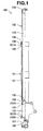
- FIG. 1 is a half sectional view showing a most extended state of a front fork;
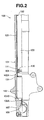
- FIG. 2 is an enlarged view of a lower portion of the front fork in FIG. 1;
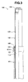
- FIG. 3 is an enlarged view of an upper portion of the front fork in FIG. 1;
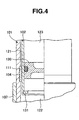
- FIG. 4 is an enlarged view of a main portion in FIG. 2;
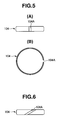
- FIGS. 5(A) and 5(B) show a bush, in which FIG. 5(A) is a front elevational view, and FIG. 5(B) is a plan view;
- FIG. 6 is a front elevational view showing a modified embodiment of a bush;
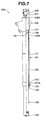
- FIG. 7 is a half cross sectional view showing a state in which an oil is filled in the front fork;
- FIG. 8 is a half cross sectional view showing a most compressed state of the front fork;
- FIGS. 9(A) and 9(B) show a modified embodiment of the front fork, in which FIG. 9(A) is a half cross sectional view showing a most compressed state, and FIG. 9(B) is a half cross sectional view showing a most extended state; and
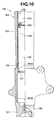
- FIG. 10 is an enlarged view of a main portion in FIG. 9(B).
-
- An erect
type front fork 100 of a two-wheeled vehicle or the like is structured, as shown in FIGS. 1 to 3, such that aninner tube 102 in a vehicle body side is slidably erected in anouter tube 101 in an axle side. Thefront fork 100 does not include a suspension spring and a damping force generating apparatus. - The
front fork 100 is structured such that a leadingend 102A of theinner tube 102 is inserted to theouter tube 101 from an upperend opening portion 101A of theouter tube 101. Further, two upper andlower bushes inner tube 102 are fitted and attached to two vertical positions of the inner periphery of theouter tube 101, in other words, an inner periphery in a side of the upperend opening portion 101A of theouter tube 101, and an inner periphery in a base end side which is apart from the upperend opening portion 101A in an axial direction. Anoil seal 105 and adust seal 106 are fitted and attached to the upperend opening portion 101A of theouter tube 101. - The base end of the
outer tube 101 is coupled to an axle via anaxle bracket 107, and theinner tube 102 is supported to a vehicle body side via upper and lower brackets (not shown). - A
bolt hole 108A is provided in a bottom portion of theaxle bracket 107 sealed to the base end of theouter tube 101, and a sealingbolt 108 is attached to and detached from thebolt hole 108A. Acap 109 is sealed to an upper end opening portion (a base end) of theinner tube 102. - Accordingly, the
front fork 100 is structured, as shown in FIG. 4, such that anannular groove 111 is formed in the inner periphery of the lower end (the base end side) of theouter tube 101 in accordance with a cutting process, and the annularlower bush 104 mentioned above is attached to an inner side of theannular groove 111. Theannular groove 111 is constituted by a concave groove in which both side portions in an axial direction are closed by a step, within the inner peripheral surface of theouter tube 101. Thelower bush 104 is constituted by an annular body as shown in FIG. 5, has a closedgap 104A formed in a straight shape along the axial direction of thebush 104 in a free state, and is attached to theannular groove 111 in a state of having the closedgap 104A. Thelower bush 104 is inserted from the lowerend opening portion 101B of theouter tube 101 in an elastically contracted state with respect to an inner diameter of theouter tube 101, under a state in which theouter tube 101 is not screwed and fastened to theaxle bracket 107, and is elastically expanded with respect to a groove bottom of theannular groove 111. - In an assembled state of the
front fork 100, an annular gap between the inner periphery of theouter tube 101 and an outer periphery of theinner tube 102 is formed smaller than a thickness of thelower bush 104, and thebush 104 attached to theannular groove 111 has the closedgap 104A - In this case, the
upper bush 103 is attached to anattachment portion 112 which is cut such that an upper end side is open, under a pressure inserted state, in an inner periphery in a side of the upperend opening portion 101A of theouter tube 101, and the closed gap becomes zero. - Therefore, in accordance with the present embodiment, the following operations and effects can be achieved.
- (1) Since it is not necessary to cut the inner periphery of the
outer tube 101 in a long range extending from an upper end portion or a lower end portion along an axial direction, at a time of forming theannular groove 111 for thelower bush 104, it is possible to shorten a working time. - Since the
annular groove 111 in the base end side of theouter tube 101 is formed in a portion as close as possible to the base end side of the outer tube main body, a run-out of theouter tube 101 is not generated at a time of forming theannular groove 111 in accordance with the cutting process, whereby it is possible to accurately form theannular groove 111. - (2) Since the
lower bush 104 is inhibited from moving in an axial direction by both end portions of theannular groove 111, thebush 104 is not displaced in the axial direction. - (3) Since the gap between the inner periphery of the
outer tube 101 and the outer periphery of theinner tube 102 is made smaller than the thickness of thebush 104, thebush 104 does not drop into the gap even if thebush 104 is contracted at an amount of the closedgap 104A. - (4) In the case that the bush is pressure inserted into the conventional attachment portion in which one end side is open, the bush is pressure inserted such that the closed gap of the bush is zero. On the contrary, in accordance with the present invention, the
bush 104 is expanded within theannular groove 111, and the closedgap 104A is generated in thebush 104. In thebush 104 in accordance with the present invention mentioned above, a friction with the outer periphery of theinner tube 102 becomes fixed from an initial stage of the stroke start in comparison with the conventional press-in bush having zero closed gap. Because thebush 104 is not closely attached to the inner periphery of theannular groove 111, whereby thebush 104 can be slightly expanded within theannular groove 111, so that it is considered that the friction at the initial stage of the start is reduced in comparison with the friction in the conventional press-in bush. Since the friction is fixed, it is possible to improve an operability of thefront fork 100. In particular, since the friction at the initial stage of the start is reduced, it is possible to improve an initial operability of thefront fork 100. - FIG. 6 shows a modified embodiment of the
bush 104, in which the closedgap 104A is formed so as to be inclined with respect to the axial direction of thebush 104. - In the
bush 104 in FIG. 6, the closedgap 104A is formed so as to be inclined with respect to the axial direction of thebush 104. As a result, a bearing surface of thebush 104 exists in all the area in a peripheral direction of thebush 104. Accordingly, in comparison with the structure in which the closed gap is formed along the axial direction, there is no portion which does not axially support the outer peripheral surface of theinner tube 102 in the peripheral direction of thebush 104, and it is possible to prevent a scratch from being generated on the outer peripheral surface of theinner tube 102 due to a slide motion with the closedgap 104A of thebush 104. - Further, in the
front fork 100, thebushes oil seal 105 can be loaded to an annular gap sectioned by two upper andlower bushes outer tube 101 and the outer periphery of theinner tube 102, and the annular gap is formed as anannular oil gap 121. - Further, a movable
partition wall member 130 is provided in the inner periphery of theinner tube 102. The movablepartition wall member 130 is provided with anoil chamber 122 sectioned together with the inner periphery of theouter tube 101 and the bottom portion of theaxle bracket 107, in a leading end side of theinner tube 102, and sections agap chamber 123 in a base end side of theinner tube 102. In the present embodiment, a movablepartition wall member 130 is provided in an inner periphery in a leading end side of theinner tube 102, and makes a volumetric capacity of theoil chamber 122 small. - The movable
partition wall member 130 is constituted by a free piston which slides along the inner periphery of theinner tube 102 in a liquid tight manner, however, may be constituted by a bladder such as a rubber or the like in which an outer edge is sealed to the inner periphery of theinner tube 102. - At a time of injecting the oil into the
front fork 100, the oil is injected into theoil chamber 122 from thebolt hole 108A of theaxle bracket 107, in a state in which thefront fork 100 is inverted such that theouter tube 101 is arranged in an upper side, theinner tube 102 is arranged in a lower side, and the movablepartition wall member 130 is brought into contact with astopper 131 provided in the leading end portion in the inner periphery of theinner tube 102, as shown in FIG. 7, and thereafter thesealing bolt 108 is sealed to thebolt hole 108A. When theouter tube 101 and theinner tube 102 are expanded and contracted in a state in which thefront fork 100 is used in an erected manner, the movablepartition wall member 130 moves upward from thestopper 131 at an amount of the volumetric capacity at which theinner tube 102 moves forward into theoil chamber 122. FIG. 8 shows a most contracted state of thefront fork 100. - At this time, the
front fork 100 communicates theannular oil gap 121 between theouter tube 101 and theinner tube 102 with theoil chamber 122 in the leading end side of theinner tube 102, and sections theannular oil gap 121 and theoil chamber 122 in a sealing manner with respect to thegas chamber 123, in the movablepartition wall member 130. In the present embodiment, theannular oil gap 121 is always communicated with theoil chamber 122 via the closedgap 104A of thelower bush 104 mentioned above. - Therefore, in accordance with the present embodiment, the following operations and effects can be achieved.
- (a) The movable
partition wall member 130 sections in a sealing manner theannular oil gap 121 between theouter tube 101 and theinner tube 102 and theoil chamber 122 in the lower portion of the movablepartition wall member 130, in a state of pushing down with respect to thegas chamber 123 in the upper portion of the movablepartition wall member 130 so as to make the volumetric capacity small. The oil attached to the outer periphery of theinner tube 102 and making an intrusion into theannular oil gap 121 lubricates theupper bush 103 and a lip of theoil seal 105 in accordance with a vertical movement of theinner tube 102. Further, the oil fully filled in theannular oil gap 121 directly lubricates thebushes partition wall member 130 executes a volume compensation and a temperature compensation in correspondence to a forward and backward movement of theinner tube 102 to theoil chamber 122 in the leading end, on the basis of the vertical movement. - The movable
partition wall member 130 is constituted by the free piston or the bladder such as the rubber or the like, however, since the movablepartition wall member 130 is constituted by a general-purpose product as is different from the specially ordered product such as the hollow formed body made of the synthetic resin pipe or the like in accordance with the prior art, the movablepartition wall member 130 is inexpensive. - As a result, it is possible to inexpensively provide the
front fork 100 in which the volumetric capacity of thegas chamber 123 is increased by reducing the volumetric capacity of thelower oil chamber 122 by the movablepartition wall member 130, an extra oil amount is reduced, a filling amount of the lubricating oil for lubricating thebush 103, theoil seal 105 and the like in theopening portion 101A of theouter tube 101 is reduced, and a weight saving is intended. - (b) Since the movable
partition wall member 130 is provided in the inner periphery in the leading end side of theinner tube 102, it is possible to make the volumetric capacity of thelower oil chamber 122 of the movablepartition wall member 130 smaller, and it is possible to further achieve the weight saving. - (c) It is possible to further achieve the inexpensiveness of the
front fork 100 in the items (a) and (b) mentioned above, by utilizing theclosed gap 104A of thebush 104 originally provided in the inner periphery of theouter tube 101 as the communication passage between theannular oil gap 121 and the leading endside oil chamber 122 of theinner tube 102. - In this case, the
front fork 100 may be structured, as shown in FIGS. 9 and 10, such that theannular oil gap 121 and theoil chamber 122 are always communicated by anoil hole 140 provided in a side wall of theinner tube 102. FIG. 9(A) shows a most contracted state of thefront fork 100, and FIGS. 9(B) and 10 show a most expanded state of thefront fork 100. In the most expanded state in FIGS. 9(A) and 10, since the movablepartition wall member 130 moves downward at an amount at which theinner tube 102 gets out of theoil chamber 122, theoil hole 140 is necessarily provided at a position in the leading end side of theinner tube 102 which is neither closed by the movablepartition wall member 130 nor open to thegas chamber 123. - It is possible to make the
front fork 100 mentioned in the items (a) and (b) further inexpensive, by arranging theoil hole 140 always communicating theoil chamber 122 in the leading end side of theinner tube 102 and theannular oil gap 121 in theinner tube 102. - At this time, the
lower bush 104 may be constituted by the annular body having theclosed gap 104A as shown in FIGS. 5 and 6, or may be constituted by an annular body continuously provided in a peripheral direction and having no closed gap. In the case that thebush 104 is constituted by the annular body having no closed gap, theoil hole 140 is not closed by thebush 104, but is communicated with theannular oil gap 121, in the most contracted state in FIG. 9(A). - Further, the
front fork 100 is not limited to the structure in which the oil is filled in theannular oil gap 121 between theouter tube 101 and theinner tube 102, but a slight amount of gas may be mixed into the oil within theannular oil gap 121. In the case that the gas is mixed into theannular oil gap 121, the working oil flows through theclosed gap 104A of thebush 104 in accordance with the telescopic stroke of theinner tube 102. Accordingly, a damping force is generated in theclosed gap 104A, and an operability of theinner tube 102 is deteriorated. In the case that no gas is mixed into theannular oil gap 121, the damping force mentioned above is not generated, and the operability of the telescopic stroke of theinner tube 102 is improved. - Further, the
front fork 100 may be constituted by a structure employing theouter tube 101 in which theaxle bracket 107 is integrally formed in the outer tube main body constituting theouter tube 101. - As heretofore explained, embodiments of the present invention have been described in detail with reference to the drawings. However, the specific configurations of the present invention are not limited to the illustrated embodiments but those having a modification of the design within the range of the presently claimed invention are also included in the present invention.
- Although the invention has been illustrated and described with respect to several exemplary embodiments thereof, it should be understood by those skilled in the art that the foregoing and various other changes, omissions and additions may be made to the present invention without departing from the spirit and scope thereof. Therefore, the present invention should not be understood as limited to the specific embodiment set out above, but should be understood to include all possible embodiments which can be encompassed within a scope of equivalents thereof with respect to the features set out in the appended claims.
Claims (7)
wherein a leading end of said inner tube is inserted into said outer tube from an opening portion of said outer tube, and two bushes guiding said inner tube are fitted and attached to an inner periphery of an opening portion side of said outer tube, and an inner periphery of a base end side apart from said opening portion in an axial direction,
wherein an annular oil gap sectioned by said two bushes is provided between said outer tube and said inner tube,
wherein a movable partition wall member is provided in an inner periphery of said inner tube, an oil chamber is sectioned in a leading end side of said inner tube, and a gas chamber is sectioned in a base end side of said inner tube, and
said annular oil gap is communicated with the oil chamber in the leading end side of said inner tube, and said annular oil gap and said oil chamber are sectioned in a sealing manner with respect to said gas chamber by said movable partition wall member.
wherein said movable partition wall member is provided in an inner periphery of the leading end side of said inner tube, and a volumetric capacity of said oil chamber is made smaller.
wherein said annular oil gap and the oil chamber in the leading end side of said inner tube are communicated via the closed gap of said bush.
wherein said closed gap is formed so as to be inclined with respect to an axial direction of the bush.
Applications Claiming Priority (4)
| Application Number | Priority Date | Filing Date | Title |
|---|---|---|---|
| JP2004077228 | 2004-03-17 | ||
| JP2004077228 | 2004-03-17 | ||
| JP2004155192 | 2004-05-25 | ||
| JP2004155192A JP2005299913A (en) | 2004-03-17 | 2004-05-25 | Front forks such as motorcycles |
Publications (2)
| Publication Number | Publication Date |
|---|---|
| EP1577206A2 true EP1577206A2 (en) | 2005-09-21 |
| EP1577206A3 EP1577206A3 (en) | 2006-08-23 |
Family
ID=34840255
Family Applications (1)
| Application Number | Title | Priority Date | Filing Date |
|---|---|---|---|
| EP04021389A Withdrawn EP1577206A3 (en) | 2004-03-17 | 2004-09-08 | Front fork of two-wheeled vehicle or the like |
Country Status (2)
| Country | Link |
|---|---|
| EP (1) | EP1577206A3 (en) |
| JP (1) | JP2005299913A (en) |
Cited By (2)
| Publication number | Priority date | Publication date | Assignee | Title |
|---|---|---|---|---|
| CN102966696A (en) * | 2011-08-30 | 2013-03-13 | 株式会社昭和 | Front fork |
| DE102019120635A1 (en) * | 2019-07-31 | 2021-02-04 | Bayerische Motoren Werke Aktiengesellschaft | Fork leg of a wheel suspension for single-track motor vehicles |
Citations (1)
| Publication number | Priority date | Publication date | Assignee | Title |
|---|---|---|---|---|
| JPH03264876A (en) | 1990-02-28 | 1991-11-26 | Koden Electron Co Ltd | Measuring method of azimuth if separation of interference of two signals |
Family Cites Families (6)
| Publication number | Priority date | Publication date | Assignee | Title |
|---|---|---|---|---|
| GB942804A (en) * | 1959-03-31 | 1963-11-27 | Svenska Aeroplan Ab | A combined springing and shock absorbing device |
| DE3725983A1 (en) * | 1987-08-05 | 1989-02-16 | Bayerische Motoren Werke Ag | Telescopic shock absorber, in particular for front wheel forks of motorbikes or the like |
| US5248159A (en) * | 1992-02-18 | 1993-09-28 | Moore James D | Lightweight self-adjusting semihydraulic suspension system |
| GB2296902B (en) * | 1995-01-16 | 1998-04-15 | Nigel John Hill | Front suspension arrangements for performance motor cycles |
| DE19653148A1 (en) * | 1996-12-19 | 1998-06-25 | Bayerische Motoren Werke Ag | Telescopic spring-loaded wheel guide |
| US6311962B1 (en) * | 1998-02-03 | 2001-11-06 | Fox Factory, Inc. | Shock absorber with external air cylinder spring |
-
2004
- 2004-05-25 JP JP2004155192A patent/JP2005299913A/en not_active Withdrawn
- 2004-09-08 EP EP04021389A patent/EP1577206A3/en not_active Withdrawn
Patent Citations (1)
| Publication number | Priority date | Publication date | Assignee | Title |
|---|---|---|---|---|
| JPH03264876A (en) | 1990-02-28 | 1991-11-26 | Koden Electron Co Ltd | Measuring method of azimuth if separation of interference of two signals |
Cited By (3)
| Publication number | Priority date | Publication date | Assignee | Title |
|---|---|---|---|---|
| CN102966696A (en) * | 2011-08-30 | 2013-03-13 | 株式会社昭和 | Front fork |
| CN102966696B (en) * | 2011-08-30 | 2016-03-16 | 株式会社昭和 | Front fork |
| DE102019120635A1 (en) * | 2019-07-31 | 2021-02-04 | Bayerische Motoren Werke Aktiengesellschaft | Fork leg of a wheel suspension for single-track motor vehicles |
Also Published As
| Publication number | Publication date |
|---|---|
| EP1577206A3 (en) | 2006-08-23 |
| JP2005299913A (en) | 2005-10-27 |
Similar Documents
| Publication | Publication Date | Title |
|---|---|---|
| US9120526B2 (en) | Front fork | |
| US6918605B2 (en) | Inverted type front fork in two-wheeled vehicle or the like | |
| US9156327B2 (en) | Suspension device | |
| JP5756392B2 (en) | Sealing device and shock absorber provided with the sealing device | |
| JP3728648B2 (en) | Front fork | |
| US8474850B2 (en) | Lubricated guide unit for a motorcycle fork tube | |
| JP4996957B2 (en) | Shock absorber and shock absorber assembly tool | |
| CN107002808A (en) | Shock absorber | |
| US9038792B2 (en) | Shock absorber | |
| US20060170185A1 (en) | Front fork in two-wheeled vehicle or the like | |
| JP4514640B2 (en) | Front fork | |
| US7048291B2 (en) | Front fork in two-wheeled vehicle or the like | |
| JP2005299913A (en) | Front forks such as motorcycles | |
| JP2006349138A (en) | Pneumatic shock absorber | |
| EP1486410A2 (en) | Front fork for a two-wheeled vehicle or the like | |
| JP6523849B2 (en) | Front fork | |
| EP1878647B1 (en) | Hydraulic shock absorber | |
| JP5642606B2 (en) | Hydraulic shock absorber | |
| JPS6243157Y2 (en) | ||
| JP2010276066A (en) | Pneumatic shock absorber | |
| ITBO980089A1 (en) | HYDROPNEUMATIC SHOCK ABSORBER, ADJUSTABLE, LOW WEIGHT, PARTICULARLY SUITABLE FOR FORMING THE LEGS OF A TELESCOPIC FORK FOR | |
| JP2012172697A (en) | Shock absorber | |
| JPH0752961Y2 (en) | accumulator | |
| JP6523850B2 (en) | Front fork | |
| JPH0554190U (en) | Oil buffer chamber structure of hydraulic shock absorber |
Legal Events
| Date | Code | Title | Description |
|---|---|---|---|
| PUAI | Public reference made under article 153(3) epc to a published international application that has entered the european phase |
Free format text: ORIGINAL CODE: 0009012 |
|
| AK | Designated contracting states |
Kind code of ref document: A2 Designated state(s): AT BE BG CH CY CZ DE DK EE ES FI FR GB GR HU IE IT LI LU MC NL PL PT RO SE SI SK TR |
|
| AX | Request for extension of the european patent |
Extension state: AL HR LT LV MK |
|
| PUAL | Search report despatched |
Free format text: ORIGINAL CODE: 0009013 |
|
| AK | Designated contracting states |
Kind code of ref document: A3 Designated state(s): AT BE BG CH CY CZ DE DK EE ES FI FR GB GR HU IE IT LI LU MC NL PL PT RO SE SI SK TR |
|
| AX | Request for extension of the european patent |
Extension state: AL HR LT LV MK |
|
| 17P | Request for examination filed |
Effective date: 20061030 |
|
| 17Q | First examination report despatched |
Effective date: 20061212 |
|
| AKX | Designation fees paid |
Designated state(s): DE IT |
|
| GRAP | Despatch of communication of intention to grant a patent |
Free format text: ORIGINAL CODE: EPIDOSNIGR1 |
|
| STAA | Information on the status of an ep patent application or granted ep patent |
Free format text: STATUS: THE APPLICATION IS DEEMED TO BE WITHDRAWN |
|
| 18D | Application deemed to be withdrawn |
Effective date: 20081001 |