EP1577152A2 - Retractable seat - Google Patents
Retractable seat Download PDFInfo
- Publication number
- EP1577152A2 EP1577152A2 EP05005268A EP05005268A EP1577152A2 EP 1577152 A2 EP1577152 A2 EP 1577152A2 EP 05005268 A EP05005268 A EP 05005268A EP 05005268 A EP05005268 A EP 05005268A EP 1577152 A2 EP1577152 A2 EP 1577152A2
- Authority
- EP
- European Patent Office
- Prior art keywords
- seat
- armrest
- aircraft
- folding
- backrest
- Prior art date
- Legal status (The legal status is an assumption and is not a legal conclusion. Google has not performed a legal analysis and makes no representation as to the accuracy of the status listed.)
- Granted
Links
Images


Classifications
-
- B—PERFORMING OPERATIONS; TRANSPORTING
- B64—AIRCRAFT; AVIATION; COSMONAUTICS
- B64D—EQUIPMENT FOR FITTING IN OR TO AIRCRAFT; FLIGHT SUITS; PARACHUTES; ARRANGEMENT OR MOUNTING OF POWER PLANTS OR PROPULSION TRANSMISSIONS IN AIRCRAFT
- B64D11/00—Passenger or crew accommodation; Flight-deck installations not otherwise provided for
- B64D11/06—Arrangements of seats, or adaptations or details specially adapted for aircraft seats
- B64D11/0639—Arrangements of seats, or adaptations or details specially adapted for aircraft seats with features for adjustment or converting of seats
- B64D11/064—Adjustable inclination or position of seats
-
- B—PERFORMING OPERATIONS; TRANSPORTING
- B60—VEHICLES IN GENERAL
- B60N—SEATS SPECIALLY ADAPTED FOR VEHICLES; VEHICLE PASSENGER ACCOMMODATION NOT OTHERWISE PROVIDED FOR
- B60N2/00—Seats specially adapted for vehicles; Arrangement or mounting of seats in vehicles
- B60N2/24—Seats specially adapted for vehicles; Arrangement or mounting of seats in vehicles for particular purposes or particular vehicles
- B60N2/30—Non-dismountable or dismountable seats storable in a non-use position, e.g. foldable spare seats
- B60N2/3038—Cushion movements
- B60N2/304—Cushion movements by rotation only
- B60N2/3045—Cushion movements by rotation only about transversal axis
- B60N2/3047—Cushion movements by rotation only about transversal axis the cushion being hinged at the back-rest
-
- B—PERFORMING OPERATIONS; TRANSPORTING
- B60—VEHICLES IN GENERAL
- B60N—SEATS SPECIALLY ADAPTED FOR VEHICLES; VEHICLE PASSENGER ACCOMMODATION NOT OTHERWISE PROVIDED FOR
- B60N2/00—Seats specially adapted for vehicles; Arrangement or mounting of seats in vehicles
- B60N2/75—Arm-rests
- B60N2/753—Arm-rests movable to an inoperative position
-
- B—PERFORMING OPERATIONS; TRANSPORTING
- B64—AIRCRAFT; AVIATION; COSMONAUTICS
- B64D—EQUIPMENT FOR FITTING IN OR TO AIRCRAFT; FLIGHT SUITS; PARACHUTES; ARRANGEMENT OR MOUNTING OF POWER PLANTS OR PROPULSION TRANSMISSIONS IN AIRCRAFT
- B64D11/00—Passenger or crew accommodation; Flight-deck installations not otherwise provided for
- B64D11/06—Arrangements of seats, or adaptations or details specially adapted for aircraft seats
- B64D11/0646—Seats characterised by special features of stationary arms, foot or head rests
Definitions
- the present invention relates to a folding seat, in particular for a passenger cabin of an airplane.
- the present invention relates to a folding seat for a Airplane, a seating group for a vehicle, an airplane with a corresponding one Folding seat and a method for supplying passengers to a seat of an aircraft.
- Conventional passenger seats for aircraft have a carrying frame with a fixed one arranged seat surface and arranged in the region of the rear edge of the seat Backrest.
- the passenger seats preferably form rows of seats, two or a plurality of juxtaposed passenger seats or seats to a seating group can be summarized, which is supported by a common support frame.
- On Each side of a seat is usually arranged an armrest.
- the seating groups are as rigid units intended for installation in the passenger cabins of the aircraft. According to the request of the airlines, it can be different Configurations come, with priority, a maximum seat capacity is sought.
- a disadvantage of a passenger cabin with a high number of seats is that due to the narrow cabin longitudinal corridors - also called traffic area - between the seat rows the entry and exit of the passengers requires a lot of time. It can ago in particular stagnation, when the passengers have to stow the hand luggage, For example, in compartments above the seats, stay in the corridor, which blocks it becomes. Usually, the cabin passages are too narrow to be adjacent to each other allow two passengers. Also in cleaning is in particular a room difficult to access between the rows of seats.
- the above object can be achieved by means of a folding seat for an aircraft, comprising a backrest, a seat and an armrest.
- the seat is pivotable.
- the armrest is down pivotable.
- this allows an increase in the traffic area, d. H. the areas in the passenger cabin of an aircraft on which the persons move can, especially when getting on and off the aircraft.
- both the seat can be swung away as well as the armrest of the seat swung away can be, so that between two successively arranged seats still enough space remains that a person can stand there.
- pivoting of the seat to the backrest causes a pivoting the armrest down.
- this folding seat allows for example a easy handling, because by pivoting or folding the seat upwards the backrest of the seat automatically pivots the armrest down, creating easy access to the space between successive seats is made possible.
- the seat and the armrest is frictionally coupled.
- handling can be simplified such that only one only handle is required to pivot seat and armrest.
- this can be advantageous in cleaning work.
- the seat and the armrest by means of at least one coupling element coupled.
- the folding seat is for placement on a corridor in an aircraft designed.
- the folding seat of the aisle seat of a seating group with two, three or more seats.
- this is the traffic area the corridor between successive rows of seats extended in which persons for example, to stow luggage between rows of seats can occur.
- a seating group is given for a vehicle, with an armrest and a Seat surface of a seat are pivotable.
- the vehicle may be an aircraft be.
- the seat of the seating group with swivel seat and swivel Armrest provided, each adjacent to the corridor.
- the traffic area of the aircraft are widened, whereby a climbing and Leaving the aircraft can be accelerated by the passengers. This too can be too contribute to a reduction in the time required to clean the aircraft.
- a "turn around" time of an aircraft be reduced.
- a Aircraft specified a folding seat according to the present invention or a Seating group according to the present invention is a Aircraft specified a folding seat according to the present invention or a Seating group according to the present invention.
- a corridor between adjacent rows of seats are made very narrow, because for boarding the passengers and for leaving the passengers each seat side seats and armrests can be folded away, causing the Traffic surface of the aircraft is increased again overall.
- the present invention as in claim 13 is a method for supplying passengers to a seat of an aircraft specified.
- this is a process for loading or Unloading the aircraft, d. H. to provide a method to boarding or debarking Passengers of an aircraft to allow.
- the seats and armrests according arranged seats or rows of seats folded up or folded away, creating a traffic area of the Aircraft can be enlarged.
- Fig. 1 shows a three-dimensional side view of a first embodiment of a Folding seat for an aircraft according to the present invention.
- Fig. 2 shows a further three-dimensional side view of a second embodiment a folding seat for an aircraft according to the present invention.
- Fig. 3 shows a further three-dimensional side view of a third embodiment a folding seat for an aircraft according to the present invention.
- FIG. 4 shows another three-dimensional view of a fourth embodiment of a Folding seat for an aircraft according to the present invention.
- Fig. 5 shows another schematic three-dimensional side view of a fifth Embodiment of a folding seat for an aircraft according to the present invention.
- Fig. 6 shows another schematic three-dimensional side view of a sixth Embodiment of a folding seat for an aircraft according to the present invention.
- Fig. 7 shows another schematic three-dimensional side view of a seventh Embodiment of a folding seat for an aircraft according to the present invention.
- Fig. 8 shows a schematic three-dimensional view of an embodiment of a Row of seats according to an embodiment of the present invention.
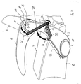
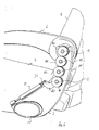
- Fig. 1 shows a schematic three-dimensional side view of a folding seat for a Aircraft according to the present invention.
- the seat or folding seat includes a Seat 2 and a backrest 4.
- an armrest 6 is shown, which in Seat direction is located on the left side of the seat.
- Fig. 1 only one armrest. 6 shown.
- another armrest 6 provided on the right side in the seat direction be.
- the seat is arranged on a support structure 10, on which the seat 2 and the backrest 4 are attached.
- a holding element 3 On the support structure 10 is also a holding element 3 is provided, on which, for example, an axle 12 and an axle 14 is provided.
- the Axle 12 may, for example, the pivot axis for the seat 2 and the backrest. 4 be.
- a separate pivot axis for the seat 2 are provided to a movement allow the seat up to the backrest 4. In other words either about the axis 12 or the corresponding other axis, not in Fig. 1 is shown, the seat 2 folded against the backrest 4 of the seat.
- the reference number 8 denotes a bottom of the seat 2.
- the seat 2 by means of a structurally reinforced seat cushion are designed.
- the armrest 6 When the seat 2 is in the sitting position, d. H. in a position such that a person is on it can sit, the armrest 6 in about 90 degrees counter to the direction of the arrow, as shown in FIG. 1, about the axis 14 are pivoted. A freedom of swinging motion is by cooperation of two stops 18 and a guide pin 16, which at the Armrest 6 is attached, provided. The stops 18 are on the holding element. 3 intended.
- the seat 2 may be upwardly as by the arrow in FIG. 1 indicated to be folded on the backrest 4.
- the armrest 6, the Preferably, when the seat is arranged in an aircraft substantially parallel to one Aircraft longitudinal direction, when the seat 2 is in the sitting position, folded up be arranged or in the position shown in Fig. 1.
- the seat 2 is rigidly connected at a point 26 with a lever 20 which is around the Rotation axis 12 is rotatable.
- the point 26 is by means of a coupling rod 24 with a point 28th and the armrest 6 connected.
- the point 28 is seen on the armrest 6 in the seat direction arranged behind the axis of rotation 14.
- points 26 and 28 Be pivot joints, by means of which the coupling rod 24 with the armrest 6 and the lever 20th connected is.
- the seat 2 by means of the lower arrow in Fig. 1, after folded up, the point 26 is displaced along the lower arrow. This transfer takes place on a circular path around the axis 12 instead. This circular path is by means of the lever 20th Are defined.
- the armrest 6 of the coupling rod 24 in such a way rotated the pivot axis 14 that the armrest 6 is folded down.
- the seat 2 is folded against the backrest 4 and the armrest. 6 folded down, the dimensions of the seat seen in sitting direction decrease essentially, whereby, for example, when the seat as the seat of a row of seats of an aircraft is now an enlarged traffic area to access other seats of the same seat row is provided.
- a traffic area of a adjacent passage for example, as a person in the by the Seat 2 and the armrest 6 can enter shared space and for example Luggage can be placed in storage compartments above or below the seats. In this way allows more, even though a person puts luggage in a storage compartment, more People can use the corridor of the aircraft, for example, to their seats come.
- the reference numeral 22 in Fig. 1 denotes a damping element, such as a Gas Spring.
- a damping element such as a Gas Spring.
- the damping element 22 is arranged between the point 26 and the retaining element 3.
- the damping element 22 can also be between any point the lever 20 and the support structure 10 may be arranged.
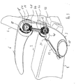
- Fig. 2 shows another lateral three-dimensional view of a second Embodiment of a folding seat according to the present invention, preferably designed for arrangement in an aircraft.
- a pivot lever 32 is arranged around the Rotation axis 12 is rotatable.
- One side of the pivot lever 32 is at a point 34 with the Damping element 22 connected.
- the point 34 can, for example, by means of a Swivel joints are designed.
- Another side of the pivot lever 32 is at one Point 36 connected to a coupling rod 30.
- the point 36 can, for example, by means of a swivel joint are designed.
- the coupling rod is at a point 38 with the Armrest 6 connected.
- the point 38 can be configured by means of a rotary joint.
- the point 38 is in the sitting direction of the seat seen in front of a pivot point of the armrest 6, d. H.
- point 34 performs a rotation the rotation axis 12 in the clockwise direction.
- the Crossover effect of this coupling is the same as described in FIG. A lifting the seat 2 causes a pivoting down of the armrest 6. Also causes a Swiveling down the armrest 6 lifting the seat 2.
- Fig. 3 shows another lateral three-dimensional view of a third Embodiment of a folding seat according to the present invention.
- the bevel gears 46 and 48 are by means of a Connected shaft 44.
- the bevel gear 42 is coupled to the axis of rotation 12 of the seat 2 and the bevel gear 50 is coupled to the rotational axis 14 of the armrest 6.
- a rotary motion the seat 2 about the axis of rotation 12 thus causes a rotation of the bevel gear 42 in Clockwise.
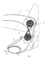
- Fig. 4 shows another lateral schematic three-dimensional view of a fourth Embodiment of a folding seat according to the present invention.
- the seat 2 and the armrest 6 by means of a cross-gear transmission chain 24, with corresponding sprockets 62 and 64 on the axes of rotation 12 and 14 cooperates coupled.
- a movement of the armrest 6 and the seat 2 is by means of the damping element 22, which by means of a lever with the Rotary axis 12 is coupled, damped.
- the damping element 22 is at the point 34 with connected to the lever 60.
- the point 34 can, for example, by means of a rotary joint be designed.
- Corresponding transmission chains 24 which is a motion-reversing Transmission guidance in the form of an eight enable, for example, drives for Stair lifts for the transport of the disabled known.
- Such transmission chains allow a deflection around all three spatial axes.
- Transmission chain 64 a guided on a hollow rail steel cable, on which in regular pitches plastic balls are applied.
- the coupling shown in FIG. 4 requires Sliding properties of the balls, for which, for example, self-lubricating plastics can be used only a minimal lubrication and are therefore little maintenance.
- guide rails provided are (not shown in Fig. 4), which can serve at the same time, a voltage of To ensure transmission chain 64.
- Fig. 5 shows another lateral schematic three-dimensional view of a folding seat according to a preferred fifth embodiment of the present invention.
- the axes of rotation 12 and 14 of the armrest 6 and the seat 2 provided by means of equal pinions 70 and 72, which are against each other roll off.
- different sized pinions 70 and 72 are used, for example, different Rotation angle of the seat 2 and the armrest 6 to realize.
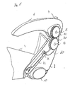
- Fig. 6 shows another lateral schematic three-dimensional view of a sixth Embodiment of a folding seat according to the present invention.
- the pinion 90 on the axis 14 and the pinion 88 on the axis 12 further pinion 84 and 86 on auxiliary axes 80 and 82nd intended.
- the pinions 84, 86, 88 and 90 roll each from each other, creating a Rotary movement of the axis 12 in an opposite rotational movement of the axis 14th is turned around.
- the pinion 84 and 86 By interposing the pinion 84 and 86, a greater distance be realized between the axes of rotation 12 and 14, as he, for example, in the in Fig. 5 shown embodiment is possible.
- Fig. 7 shows another lateral schematic three-dimensional view of a seventh Embodiment of a seat according to the present invention.
- the in Fig. 7 illustrated arrangement comprises, similar to the arrangement shown in Fig. 5, two Pinion 92 and 94 on the axes 12 and 14.
- a gate 98 is provided which has a slot 100 into which a pin 96th engages on the pinion 94.
- the pinion 94 is free-rotating on the axis of rotation 14 and not with coupled to the axis of rotation 14.
- the pinion 92 is coupled to the rotation axis 12.
- the Gate 98 is fixedly arranged on the axis of rotation 14 and in this way with the Armrest 6 coupled.
- the provision of the gate 98 allows the Armrest 6 can be swiveled 90 degrees upwards when the seat 2 is folded down can.
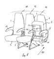
- Fig. 8 shows a simplified three-dimensional view of a row of seats according to a Embodiment of the present invention.
- the Seat row three individual seats 110, 112 and 114, wherein the row of seats rigid armrests 116 having.
- the seat 2 and the armrest 6 are not rigidly coupled. Ie. one Fold up the seat 2, as shown in Fig. 8, does not automatically cause a after Swiveling the armrest 6 downwards into the vertical downwards-pointing rest position.
- a Nachobenklappen the seat 2 a locking of Armrest 6 solved, so that the armrest 6 in the position shown in Fig. 8 simply by Actuation of an operator can be folded down.
- a bottom of the seat 2 can For example, be referred to as 120 seat boxes.
- the seat 2 are biased by a spring, so that when a person of the Seat 2 rises, the seat 2 is automatically folded onto the seat back 4. According to The present invention then automatically the armrest 6 down in the vertical Rest position folded away.
- the armrests can each have a mechanism as in Figs. 1 to 7 show.
Landscapes
- Engineering & Computer Science (AREA)
- Aviation & Aerospace Engineering (AREA)
- Transportation (AREA)
- Mechanical Engineering (AREA)
- Seats For Vehicles (AREA)
- Chairs For Special Purposes, Such As Reclining Chairs (AREA)
Abstract
Description
Die vorliegende Erfindung betrifft einen Klappsitz, insbesondere für eine Passagierkabine eines Flugzeuges. Insbesondere betrifft die vorliegende Erfindung einen Klappsitz für ein Flugzeug, eine Sitzgruppe für ein Fahrzeug, ein Flugzeug mit einem entsprechenden Klappsitz sowie ein Verfahren zum Zuleiten von Passagieren zu einem Sitz eines Flugzeugs. The present invention relates to a folding seat, in particular for a passenger cabin of an airplane. In particular, the present invention relates to a folding seat for a Airplane, a seating group for a vehicle, an airplane with a corresponding one Folding seat and a method for supplying passengers to a seat of an aircraft.
Herkömmliche Passagiersitze für Flugzeuge haben ein Tragegestell mit einer fest darauf angeordneten Sitzfläche und einer im Bereich der Hinterkante der Sitzfläche angeordneten Rückenlehne. In Flugzeugen bilden die Passagiersitze vorzugsweise Sitzreihen, wobei zwei oder mehrere nebeneinander angeordnete Passagiersitze oder Sitze zu einer Sitzgruppe zusammengefasst sein können, die von einem gemeinsamen Tragegestell getragen wird. Auf jeder Seite eines Sitzes ist üblicherweise eine Armlehne angeordnet. Die Sitzgruppen sind als starre Einheiten für die Montage in den Passagierkabinen der Flugzeuge vorgesehen. Entsprechend der Anforderung der Airlines kann es dabei zu unterschiedlichen Konfigurationen kommen, wobei vorrangig eine größtmögliche Sitzkapazität angestrebt wird. Ein Nachteil einer Passagierkabine mit einer hohen Sitzanzahl besteht darin, dass aufgrund der schmalen Kabinenlängsgänge ― auch Verkehrsfläche genannt ― zwischen den Sitzreihen das Ein- und Aussteigen der Passagiere einen hohen Zeitaufwand erfordert. Es können vor allem dann Stockungen entstehen, wenn die Passagiere zum Verstauen des Handgepäcks, beispielsweise in Fächern über den Sitzen, im Gang stehen bleiben, wodurch dieser blockiert wird. Üblicherweise sind die Kabinengänge zu schmal, um ein Aneinandervorbeigehen zweier Fluggäste zu ermöglichen. Auch bei Reinigungsarbeiten ist insbesondere ein Raum zwischen den Sitzreihen schwer zugänglich.Conventional passenger seats for aircraft have a carrying frame with a fixed one arranged seat surface and arranged in the region of the rear edge of the seat Backrest. In aircraft, the passenger seats preferably form rows of seats, two or a plurality of juxtaposed passenger seats or seats to a seating group can be summarized, which is supported by a common support frame. On Each side of a seat is usually arranged an armrest. The seating groups are as rigid units intended for installation in the passenger cabins of the aircraft. According to the request of the airlines, it can be different Configurations come, with priority, a maximum seat capacity is sought. A disadvantage of a passenger cabin with a high number of seats is that due to the narrow cabin longitudinal corridors - also called traffic area - between the seat rows the entry and exit of the passengers requires a lot of time. It can ago in particular stagnation, when the passengers have to stow the hand luggage, For example, in compartments above the seats, stay in the corridor, which blocks it becomes. Usually, the cabin passages are too narrow to be adjacent to each other allow two passengers. Also in cleaning is in particular a room difficult to access between the rows of seats.
Die Bodenzeit zwischen aufeinanderfolgenden Flügen eines Flugzeugs ― auch "Turn around"-Zeit genannt ― ist für die Wirtschaftlichkeit eines Verkehrsflugzeuges von maßgeblicher Bedeutung. Es ist somit notwendig, dass trotz einer hohen Sitzbelegung in der Passagierkabine die Verkehrsfläche so ausgestaltet ist, dass ein schnelles Ein- und Aussteigen der Passagiere ermöglicht wird und der Zeitaufwand für notwendige Bodenarbeiten minimiert wird.The ground time between successive flights of an aircraft - also "Turn called for "time - is for the economic efficiency of a commercial aircraft significant importance. It is thus necessary that, despite a high seat occupancy in the Passenger cabin the traffic area is designed so that a quick entry and exit Passengers is enabled and minimized the time required for necessary ground work becomes.
Es ist eine Aufgabe der vorliegenden Erfindung, eine Verkehrsfläche eines Flugzeugs, insbesondere bei einem Aufenthalt auf dem Boden, zu vergrößern. It is an object of the present invention to provide a traffic surface of an aircraft, especially when staying on the ground, to enlarge.
Gemäß einem Ausführungsbeispiel der vorliegenden Erfindung, wie in Anspruch 1 angegeben, kann die obige Aufgabe mittels eines Klappsitzes für ein Flugzeug gelöst werden, der eine Rückenlehne, eine Sitzfläche und eine Armlehne umfasst. Die Sitzfläche ist schwenkbar. Bei einem Schwenken der Sitzfläche ist die Armlehne nach unten verschwenkbar.According to an embodiment of the present invention as in claim 1 indicated, the above object can be achieved by means of a folding seat for an aircraft, comprising a backrest, a seat and an armrest. The seat is pivotable. When swinging the seat, the armrest is down pivotable.
In vorteilhafter Art und Weise ermöglicht dies eine Vergrößerung der Verkehrsfläche, d. h. der Flächen in der Passagierkabine eines Flugzeuges, auf der sich die Personen bewegen können, insbesondere beim Be- und Entsteigen des Flugzeugs. So kann beispielsweise ein Passagier zum Verstauen des Gepäcks in Fächern über den Sitzen oder unter den Sitzen zwischen zwei aufeinanderfolgende Sitzreihen treten und somit den Gang freimachen, so dass weitere Passagiere zu ihren Plätzen gehen können. Ermöglicht wird dies dadurch, dass sowohl die Sitzfläche weggeschwenkt werden kann als auch die Armlehne des Sitzes weggeschwenkt werden kann, so dass zwischen zwei nacheinander angeordneten Sitzen noch genügend Platz verbleibt, dass eine Person dort stehen kann.In an advantageous manner, this allows an increase in the traffic area, d. H. the areas in the passenger cabin of an aircraft on which the persons move can, especially when getting on and off the aircraft. For example, a Passenger stowing luggage in compartments above seats or under seats between two successive rows of seats and thus clear the course, so that other passengers can go to their seats. This is made possible by the fact that both the seat can be swung away as well as the armrest of the seat swung away can be, so that between two successively arranged seats still enough space remains that a person can stand there.
Gemäß einem weiteren Ausführungsbeispiel der vorliegenden Erfindung, wie in Anspruch 2
angegeben, bewirkt ein Anschwenken der Sitzfläche an die Rückenlehne ein Verschwenken
der Armlehne nach unten. Vorteilhaft ermöglicht dieser Klappsitz beispielsweise eine
einfache Handhabung, da durch Anschwenken oder Anklappen der Sitzfläche nach oben an
die Rückenlehne des Sitzes automatisch die Armlehne nach unten verschwenkt wird, wodurch
ein einfacher Zugang zu dem Raum zwischen aufeinanderfolgenden Sitzen ermöglicht wird.According to another embodiment of the present invention as in
Gemäß einem weiteren Ausführungsbeispiel der vorliegenden Erfindung, wie in Anspruch 3
angegeben, ist die Sitzfläche und die Armlehne kraftschlüssig gekoppelt. Auf diese Art und
Weise kann beispielsweise eine Handhabung derart vereinfacht werden, dass lediglich ein
einziger Handgriff erforderlich ist, um Sitzfläche und Armlehne zu verschwenken.
Insbesondere kann dies bei Reinigungsarbeiten vorteilhaft sein. According to another embodiment of the present invention as in
Gemäß einem weiteren Ausführungsbeispiel der vorliegenden Erfindung, wie in Anspruch 4
angegeben, sind die Sitzfläche und die Armlehne mittels zumindest einem Koppelelement
gekoppelt.According to a further embodiment of the present invention, as in
Gemäß einem weiteren vorteilhaften Ausführungsbeispiel der vorliegenden Erfindung, wie in Anspruch 5 angegeben, ist der Klappsitz zur Anordnung an einen Gang in einem Flugzeug ausgestaltet. Beispielsweise kann der Klappsitz der Gangsitz einer Sitzgruppe mit zwei, drei oder mehreren Sitzen sein. In vorteilhafter Art und Weise wird dadurch die Verkehrsfläche des Ganges zwischen aufeinanderfolgenden Sitzreihen erweitert, in dem Personen beispielsweise zum Verstauen von Gepäckstücken zwischen Sitzreihen treten können.According to a further advantageous embodiment of the present invention, as in Claim 5, the folding seat is for placement on a corridor in an aircraft designed. For example, the folding seat of the aisle seat of a seating group with two, three or more seats. In an advantageous manner, this is the traffic area the corridor between successive rows of seats extended in which persons for example, to stow luggage between rows of seats can occur.
Weitere vorteilhafte Ausführungsbeispiele des Klappsitzes gemäß der vorliegenden Erfindung
sind in den Ansprüchen 6 und 7 angegeben.Further advantageous embodiments of the folding seat according to the present invention
are specified in
Gemäß einem weiteren Ausführungsbeispiel der vorliegenden Erfindung, wie in Anspruch 8
angegeben, wird eine Sitzgruppe für ein Fahrzeug angegeben, wobei eine Armlehne und eine
Sitzfläche eines Sitzes verschwenkbar sind. Beispielsweise kann das Fahrzeug ein Flugzeug
sein. Insbesondere bei einem Flugzeug mit jeweils zwei Sitzen auf jeder Seite des Ganges ist
insbesondere der Sitz der Sitzgruppe mit schwenkbarer Sitzfläche und schwenkbarer
Armlehne versehen, der jeweils an den Gang angrenzt. In vorteilhafter Art und Weise kann
damit die Verkehrsfläche des Flugzeuges ausgeweitet werden, wodurch ein Besteigen und
Verlassen des Flugzeuges durch die Passagiere beschleunigt werden kann. Auch kann dies zu
einer Verringerung einer Zeit beitragen, die zur Reinigung des Flugzeuges benötigt wird.
' Insgesamt kann in vorteilhafter Art und Weise eine "Turn around"-Zeit eines Flugzeuges
verringert werden.According to another embodiment of the present invention as in
Weitere vorteilhafte Ausführungsbeispiele der Sitzgruppe gemäß der vorliegenden Erfindung sind in den Ansprüchen 9 bis 11 angegeben. Further advantageous embodiments of the seating group according to the present invention are given in claims 9 to 11.
Gemäß einem weiteren vorteilhaften Ausführungsbeispiel der vorliegenden Erfindung ist ein Flugzeug angegeben, das einen Klappsitz gemäß der vorliegenden Erfindung oder eine Sitzgruppe gemäß der vorliegenden Erfindung aufweist. In vorteilhafter Art und Weise kann solch ein Flugzeug eine verringerte "Turn around"-Zeit aufweisen. Überdies kann beispielsweise ein Gang zwischen benachbarten Sitzreihen sehr schmal ausgestaltet werden, da zum Zusteigen der Passagiere und für ein Verlassen der Passagiere die jeweils gangseitigen Sitzflächen und Armlehnen weggeklappt werden können, wodurch die Verkehrsfläche des Flugzeugs insgesamt wieder vergrößert wird.According to a further advantageous embodiment of the present invention is a Aircraft specified a folding seat according to the present invention or a Seating group according to the present invention. In an advantageous manner can such aircraft have a reduced turn around time. Moreover, can For example, a corridor between adjacent rows of seats are made very narrow, because for boarding the passengers and for leaving the passengers each seat side seats and armrests can be folded away, causing the Traffic surface of the aircraft is increased again overall.
Gemäß einem weiteren Ausführungsbeispiel der vorliegenden Erfindung, wie in Anspruch 13 angegeben, wird ein Verfahren zum Zuleiten von Passagieren zu einem Sitz eines Flugzeuges angegeben. In anderen Worten handelt es sich hierbei um ein Verfahren zum Be- oder Entladen des Flugzeugs, d. h. um ein Verfahren, um das Boarden oder Deboarden von Passagieren eines Flugzeugs zu ermöglichen. In vorteilhafter Art und Weise werden gemäß der vorliegenden Erfindung die Sitzflächen und Armlehnen entsprechend angeordneter Sitze oder Sitzreihen hochgeklappt bzw. weggeklappt, wodurch eine Verkehrsfläche des Flugzeuges vergrößert werden kann.According to another embodiment of the present invention as in claim 13 is a method for supplying passengers to a seat of an aircraft specified. In other words, this is a process for loading or Unloading the aircraft, d. H. to provide a method to boarding or debarking Passengers of an aircraft to allow. In an advantageous manner according to the present invention, the seats and armrests according arranged seats or rows of seats folded up or folded away, creating a traffic area of the Aircraft can be enlarged.
Im Folgenden werden vorteilhafte Ausführungsbeispiele der vorliegenden Erfindung mit Verweis auf die folgenden Figuren beschrieben.The following are advantageous embodiments of the present invention with Reference to the following figures described.
Fig. 1 zeigt eine dreidimensionale Seitenansicht eines ersten Ausführungsbeispiels eines Klappsitzes für ein Flugzeug gemäß der vorliegenden Erfindung.Fig. 1 shows a three-dimensional side view of a first embodiment of a Folding seat for an aircraft according to the present invention.
Fig. 2 zeigt eine weitere dreidimensionale Seitenansicht eines zweiten Ausführungsbeispiels eines Klappsitzes für ein Flugzeug gemäß der vorliegenden Erfindung. Fig. 2 shows a further three-dimensional side view of a second embodiment a folding seat for an aircraft according to the present invention.
Fig. 3 zeigt eine weitere dreidimensionale Seitenansicht eines dritten Ausführungsbeispiels eines Klappsitzes für ein Flugzeug gemäß der vorliegenden Erfindung.Fig. 3 shows a further three-dimensional side view of a third embodiment a folding seat for an aircraft according to the present invention.
Fig. 4 zeigt eine weitere dreidimensionale Ansicht eines vierten Ausführungsbeispiels eines Klappsitzes für ein Flugzeug gemäß der vorliegenden Erfindung.4 shows another three-dimensional view of a fourth embodiment of a Folding seat for an aircraft according to the present invention.
Fig. 5 zeigt eine weitere schematisierte dreidimensionale Seitenansicht eines fünften Ausführungsbeispiels eines Klappsitzes für ein Flugzeug gemäß der vorliegenden Erfindung.Fig. 5 shows another schematic three-dimensional side view of a fifth Embodiment of a folding seat for an aircraft according to the present invention.
Fig. 6 zeigt eine weitere schematisierte dreidimensionale Seitenansicht eines sechsten Ausführungsbeispiels eines Klappsitzes für ein Flugzeug gemäß der vorliegenden Erfindung.Fig. 6 shows another schematic three-dimensional side view of a sixth Embodiment of a folding seat for an aircraft according to the present invention.
Fig. 7 zeigt eine weitere schematisierte dreidimensionale Seitenansicht eines siebten Ausführungsbeispiels eines Klappsitzes für ein Flugzeug gemäß der vorliegenden Erfindung.Fig. 7 shows another schematic three-dimensional side view of a seventh Embodiment of a folding seat for an aircraft according to the present invention.
Fig. 8 zeigt eine schematisierte dreidimensionale Ansicht eines Ausführungsbeispiels einer Sitzreihe gemäß einem Ausführungsbeispiel der vorliegenden Erfindung.Fig. 8 shows a schematic three-dimensional view of an embodiment of a Row of seats according to an embodiment of the present invention.
In der folgenden Beschreibung werden für gleiche oder sich entsprechende Elemente die gleichen Bezugsziffern verwendet.In the following description, for the same or corresponding elements, the same reference numerals used.
Fig. 1 zeigt eine schematisierte dreidimensionale Seitenansicht eines Klappsitzes für ein
Flugzeug gemäß der vorliegenden Erfindung. Der Sitz bzw. Klappsitz umfasst eine
Sitzfläche 2 sowie eine Rückenlehne 4. In Fig. 1 ist eine Armlehne 6 dargestellt, die sich in
Sitzrichtung auf der linken Seite des Sitzes befindet. In Fig. 1 ist lediglich eine Armlehne 6
dargestellt. Ebenfalls kann in spiegelverkehrter Art und Weise mit im Wesentlichen dem
gleichen Aufbau eine weitere Armlehne 6 auf der in Sitzrichtung rechten Seite vorgesehen
sein. Vorzugsweise ist eine dem Gang zugewandte Armlehne einer Sitzfläche mit der
Sitzfläche gekoppelt und bei einem nach oben Schwenken der Sitzfläche nach unten
verschwenkbar. Der Sitz ist auf einer Tragestruktur 10 angeordnet, auf der die Sitzfläche 2
sowie die Rückenlehne 4 angebracht sind. An der Tragestruktur 10 ist ferner ein Halteelement
3 vorgesehen, an dem beispielsweise eine Achse 12 sowie eine Achse 14 vorgesehen ist. Die
Achse 12 kann beispielsweise die Schwenkachse für die Sitzfläche 2 und der Rückenlehne 4
sein. Jedoch kann gemäß einem weiteren Ausführungsbeispiel der vorliegenden Erfindung
auch eine separate Schwenkachse für die Sitzfläche 2 vorgesehen werden, um eine Bewegung
der Sitzfläche nach oben an die Rückenlehne 4 zu ermöglichen. In anderen Worten wird
entweder um die Achse 12 oder um die entsprechend andere Achse, die in Fig. 1 nicht
dargestellt ist, die Sitzfläche 2 an die Rückenlehne 4 des Sitzes angeklappt. Die Bezugsziffer
8 bezeichnet eine Unterseite der Sitzfläche 2. Beispielsweise kann die Sitzfläche 2 mittels
eines strukturverstärkten Sitzpolsters ausgestaltet werden.Fig. 1 shows a schematic three-dimensional side view of a folding seat for a
Aircraft according to the present invention. The seat or folding seat includes a
Seat 2 and a
Wenn die Sitzfläche 2 in Sitzposition ist, d. h. in einer Position derart, dass eine Person darauf
sitzen kann, kann die Armlehne 6 in etwa um 90 Grad entgegen der Pfeilrichtung, wie in Fig.
1 dargestellt ist, um die Achse 14 geschwenkt werden. Eine Freiheit der Schwenkbewegung
wird durch Zusammenwirken von zwei Anschlägen 18 und einem Führungsstift 16, der an der
Armlehne 6 angebracht ist, vorgesehen. Die Anschläge 18 sind an dem Halteelement 3
vorgesehen.When the
In anderen Worten kann die Sitzfläche 2 nach oben, wie mittels des Pfeils in Fig. 1
angegeben, an die Rückenlehne 4 angeklappt werden. Ebenfalls kann die Armlehne 6, die
vorzugsweise bei Anordnung des Sitzes in einem Flugzeug im Wesentlichen parallel zu einer
Flugzeuglängsrichtung ist, wenn die Sitzfläche 2 in Sitzposition ist, nach oben geklappt
werden bzw. in der in Fig. 1 dargestellten Position angeordnet sein.In other words, the
Die Sitzfläche 2 ist starr an einem Punkt 26 mit einem Hebel 20 verbunden, der um die
Drehachse 12 drehbar ist. Der Punkt 26 ist mittels einer Koppelstange 24 mit einem Punkt 28
und der Armlehne 6 verbunden. Der Punkt 28 ist an der Armlehne 6 in Sitzrichtung gesehen
hinter der Drehachse 14 angeordnet. Die Punkte 26 und 28 können beispielsweise
Drehgelenke sein, mittels denen die Koppelstange 24 mit der Armlehne 6 und dem Hebel 20
verbunden ist. Wird nun die Sitzfläche 2, mittels des unteren Pfeils in Fig. 1 dargestellt, nach
oben geklappt, wird der Punkt 26 entlang des unteren Pfeils versetzt. Diese Versetzung findet
auf einer Kreisbahn um die Achse 12 statt. Diese Kreisbahn wird mittels des Hebels 20
definiert. Durch diese Versetzung wird die Armlehne 6 von der Koppelstange 24 derart um
die Drehachse 14 gedreht, dass die Armlehne 6 nach unten geklappt wird. Vorzugsweise wird
die Armlehne 6, in der in Fig. 1 gezeigten Darstellung, um etwa 90 Grad aus der in Fig. 1
dargestellten Position gegen den Uhrzeigersinn nach unten weggeschwenkt, so dass sie im
Wesentlichen seitlich eine Verlängerung zu der Rückenlehne 4 darstellt.The
Dadurch, dass die Sitzfläche 2 an die Rückenlehne 4 angeklappt wird und die Armlehne 6
nach unten weggeklappt wird, verringern sich die Ausmaße des Sitzes in Sitzrichtung gesehen
wesentlich, wodurch beispielsweise, wenn der Sitz als Sitz einer Sitzreihe eines Flugzeugs
angeordnet ist, nun ein vergrößerter Verkehrsbereich zum Zugang zu weiteren Sitzen der
gleichen Sitzreihe zur Verfügung gestellt wird. Auch kann eine Verkehrsfläche eines
angrenzenden Ganges vergrößert werden, da beispielsweise eine Person in den durch die
Sitzfläche 2 und die Armlehne 6 freigegebenen Raum eintreten kann und beispielsweise
Gepäck in Staufächern über oder unter den Sitzen ablegen kann. Auf diese Art und Weise
wird ermöglicht, dass, obwohl eine Person gerade Gepäck in ein Staufach legt, weitere
Personen den Gang des Flugzeuges nutzen können, um beispielsweise zu ihren Sitzen zu
kommen.Characterized in that the
Die Bezugsziffer 22 in Fig. 1 bezeichnet ein Dämpfungselement, wie beispielsweise eine
Gasdruckfeder. Durch Anordnung dieses Dämpfungselements kann beispielsweise eine
Bewegung der Sitzfläche 2 und der Armlehne 6 gedämpft werden, wodurch in vorteilhafter
Art und Weise beispielsweise eine Gefahr, dass beispielsweise ein Kind eine Hand zwischen
der Armlehne 6 und der Sitzfläche 2 einklemmt, verringert wird.The
Das Dämpfungselement 22 ist zwischen dem Punkt 26 und dem Halteelement 3 angeordnet.
Beispielsweise kann das Dämpfungselement 22 auch zwischen einem beliebigen Punkt auf
dem Hebel 20 und der Tragestruktur 10 angeordnet sein.The damping
Durch die Koppelung der Armlehne 6 mit der Sitzfläche 2 wird beispielsweise erzielt, dass
bei einem Anheben der Sitzfläche 2 die Armlehne 6 nach unten geklappt wird bzw. bei einem
Nachuntenklappen der Armlehne 6 die Sitzfläche 2 nach oben geklappt wird. Dies ermöglicht
ein einhändiges Handhaben des Sitzes, d. h. ein einhändiges Anklappen der Armlehne 6 und
der Sitzfläche 2. Die Anordnung der Koppelstange 24 an dem Hebel 20, der mit der
Sitzfläche 2 gekoppelt ist (wobei der Hebel 20 als Exzenterscheibe ausgestaltet sein kann),
mit einem Punkt der Armlehne 6, der in Sitzrichtung hinter der Drehachse 14 der Armlehne
liegt, bewirkt eine Umdrehung des Drehsinns der Sitzfläche 2 und der Armlehne 6 derart,
dass, wie in Fig. 1 dargestellt, die Armlehne 6 entgegen des Uhrzeigersinns gedreht wird und
die Sitzfläche 2 im Uhrzeigersinn an die Rückenlehne 4 angeklappt wird.By coupling the
Fig. 2 zeigt eine weitere seitliche dreidimensionale Ansicht eines zweiten
Ausführungsbeispiels eines Klappsitzes gemäß der vorliegenden Erfindung, der vorzugsweise
zur Anordnung in einem Flugzeug ausgestaltet ist. Im Gegensatz zu dem in Fig. 1
dargestellten Ausführungsbeispiel ist ein Schwenkhebel 32 angeordnet, der um die
Drehachse 12 drehbar ist. Eine Seite des Schwenkhebels 32 ist an einem Punkt 34 mit dem
Dämpfungselement 22 verbunden. Der Punkt 34 kann beispielsweise mittels eines
Drehgelenks ausgestaltet werden. Eine andere Seite des Schwenkhebels 32 ist an einem
Punkt 36 mit einer Koppelstange 30 verbunden. Der Punkt 36 kann beispielsweise mittels
eines Drehgelenks ausgestaltet werden. Die Koppelstange ist an einem Punkt 38 mit der
Armlehne 6 verbunden. Der Punkt 38 kann mittels eines Drehgelenks ausgestaltet werden. Fig. 2 shows another lateral three-dimensional view of a second
Embodiment of a folding seat according to the present invention, preferably
designed for arrangement in an aircraft. In contrast to that in FIG. 1
illustrated embodiment, a
Der Punkt 38 liegt in Sitzrichtung des Sitzes gesehen vor einem Drehpunkt der Armlehne 6,
d. h. vor der Drehachse 14 der Armlehne 6. Wird nun die Sitzfläche 2, mittels des unteren
Pfeils in Fig. 2 dargestellt, an die Rückenlehne 4 angeklappt, führt Punkt 34 eine Drehung um
die Drehachse 12 im Uhrzeigersinn aus. Durch die Koppelung der Punkte 38 und 36 wird die
Armlehne 6 bei einem Hochklappen der Sitzfläche 2 nach unten geklappt. Dies ist mittels des
oberen Pfeils in Fig. 2 dargestellt. Im Gegensatz zu der in Fig. 1 gezeigten Anordnung ist das
untere Ende der Koppelstange 30 an dem Punkt 36 hinter der Drehachse 12 der Sitzfläche 2
angeordnet. Der Schwenkhebel 32, dessen vorderes Ende das Dämpfungselement 22
aufnimmt, ist hierfür hinter die Sitzflächen der Drehachse 12 hinaus verlängert. Die
Überkreuzwirkung dieser Koppelung ist die Gleiche wie in Fig. 1 beschrieben. Ein Anheben
der Sitzfläche 2 bewirkt ein Herabschwenken der Armlehne 6. Auch bewirkt ein
Herabschwenken der Armlehne 6 ein Anheben der Sitzfläche 2.The
Fig. 3 zeigt eine weitere seitliche dreidimensionale Ansicht eines dritten
Ausführungsbeispiels eines Klappsitzes gemäß der vorliegenden Erfindung. Im Gegensatz zu
den in den Fig. 1 und 2 dargestellten Ausführungsbeispielen sind Sitzfläche 2 und
Armlehne 6, an dem in Fig. 3 dargestellten Ausführungsbeispiel, über einen Satz von
Kegelräder 42, 46, 48 und 50 verbunden. Die Kegelräder 46 und 48 sind mittels einer
Welle 44 verbunden. Das Kegelrad 42 ist mit der Drehachse 12 der Sitzfläche 2 gekoppelt
und das Kegelrad 50 ist mit der Drehachse 14 der Armlehne 6 gekoppelt. Eine Drehbewegung
der Sitzfläche 2 um die Drehachse 12 bewirkt damit eine Drehung des Kegelrades 42 im
Uhrzeigersinn. Diese Drehung wird auf das Kegelrad 46 übertragen und von dem Kegelrad 46
über die Welle 44 auf das Kegelrad 48 übertragen, das wiederum diese Drehung in eine
Drehung entgegen des Uhrzeigersinnes des Kegelrades 50 überträgt. Da die Kegelräder 42
und 50 mit den entsprechenden Drehachsen 12 und 14 gekoppelt sind, bewirkt
dementsprechend ein Hochklappen der Sitzfläche 2 ein Herunterklappen der Armlehne 6 und
vice versa. Die mittels der Pfeile in Fig. 3 angezeigte Drehrichtungsumkehr ist gegeben, da
die Kegelräder 42 und 50 die Drehachsen 12 und 14 der zu verbindenden Sitzteile 2 und 6
nicht übergreifen, sondern nur die einander zugewandten Sektoren des Kegelrades 50 der
Armlehne und des Kegelrades 42 der Sitzfläche verbinden. Vorteilhaft kann eine solche
Kopplung mittels Kegelräder Drehachsen von Armlehnen und Sitzflächen koppeln, wo ein
vergrößerter Abstand zwischen den Drehachsen 12 und 14 erforderlich ist.Fig. 3 shows another lateral three-dimensional view of a third
Embodiment of a folding seat according to the present invention. In contrast to
the embodiments shown in FIGS. 1 and 2 are
Fig. 4 zeigt eine weitere seitliche schematische dreidimensionale Ansicht eines vierten
Ausführungsbeispiels eines Klappsitzes gemäß der vorliegenden Erfindung. In dem in Fig. 4
dargestellten Ausführungsbeispiel sind die Sitzfläche 2 und die Armlehne 6 mittels einer
überkreuzwirkenden Transmissionskette 24, die mit entsprechenden Kettenrädern 62 und 64
auf den Drehachsen 12 und 14 zusammenwirkt, gekoppelt. Eine Bewegung der Armlehne 6
und der Sitzfläche 2 wird mittels des Dämpfungselements 22, das mittels eines Hebels mit der
Drehachse 12 gekoppelt ist, gedämpft. Das Dämpfungselement 22 ist an dem Punkt 34 mit
dem Hebel 60 verbunden. Der Punkt 34 kann beispielsweise mittels eines Drehgelenks
ausgestaltet werden. Entsprechende Transmissionsketten 24, die eine bewegungsumkehrende
Transmissionsführung in Form einer Acht ermöglichen, sind beispielsweise aus Antrieben für
Treppenaufzüge zum Behindertentransport bekannt. Solche Transmissionsketten ermöglichen
eine Umlenkung um alle drei Raumachsen. Beispielsweise umfasst solch eine
Transmissionskette 64 ein auf einer Hohlschiene geführtes Stahlseil, auf welches in
regelmäßigen Teilungsabständen Kunststoffkugeln aufgebracht sind. Diese Kunststoffkugeln
stellen zusammen mit den entsprechenden Vertiefungen in den Kettenrädern 62 und 66, die
auch als Transmissionsräder bezeichnet werden können, den nötigen Form- bzw. Kraftschluss
her. In vorteilhafter Art und Weise benötigt die in Fig. 4 dargestellte Kopplung durch
Gleiteigenschaften der Kugeln, für welche beispielsweise selbstschmierende Kunststoffe
verwendet werden können, nur eine minimale Schmierung und sind damit wenig
wartungsintensiv.Fig. 4 shows another lateral schematic three-dimensional view of a fourth
Embodiment of a folding seat according to the present invention. In the in Fig. 4
illustrated embodiment, the
In einer Variante dieses Ausführungsbeispiels können beispielsweise, um ein Kollidieren der
Kugeln an einem Kreuzungspunkt der Acht zu vermeiden, Führungsschienen vorgesehen
werden (in Fig. 4 nicht dargestellt), welche zugleich dazu dienen können, eine Spannung der
Transmissionskette 64 zu gewährleisten.In a variant of this embodiment, for example, to collide the
To avoid bullets at a crossing point of the eight, guide rails provided
are (not shown in Fig. 4), which can serve at the same time, a voltage of
To ensure
Fig. 5 zeigt eine weitere seitliche schematische dreidimensionale Ansicht eines Klappsitzes
gemäß einem bevorzugten fünften Ausführungsbeispiel der vorliegenden Erfindung. In dem
in Fig. 5 gezeigten Ausführungsbeispiel sind die Drehachsen 12 und 14 der Armlehne 6 und
der Sitzfläche 2 mittels gleich großen Ritzeln 70 und 72 versehen, die sich gegeneinander
abwälzen. Gemäß einer Variante des vorliegenden Ausführungsbeispiels können
unterschiedlich große Ritzel 70 und 72 verwendet werden, um beispielsweise unterschiedliche
Drehwinkel der Sitzfläche 2 und der Armlehne 6 zu realisieren.Fig. 5 shows another lateral schematic three-dimensional view of a folding seat
according to a preferred fifth embodiment of the present invention. By doing
shown in Fig. 5 embodiment, the axes of
Fig. 6 zeigt eine weitere seitliche schematische dreidimensionale Ansicht eines sechsten
Ausführungsbeispiels eines Klappsitzes gemäß der vorliegenden Erfindung. Im Gegensatz zu
der in Fig. 5 gezeigten Anordnung sind hier zwischen dem Ritzel 90 auf der Achse 14 und
dem Ritzel 88 auf der Achse 12 weitere Ritzel 84 und 86 auf Hilfsachsen 80 und 82
vorgesehen. Die Ritzel 84, 86, 88 und 90 wälzen jeweils aufeinander ab, wodurch eine
Drehbewegung der Achse 12 in eine entgegengesetzte Drehbewegung der Achse 14
umgedreht wird. Durch das Zwischenschalten der Ritzel 84 und 86 kann ein größerer Abstand
zwischen den Drehachsen 12 und 14 realisiert werden, als er beispielsweise in dem in Fig. 5
gezeigten Ausführungsbeispiel möglich ist.Fig. 6 shows another lateral schematic three-dimensional view of a sixth
Embodiment of a folding seat according to the present invention. In contrast to
the arrangement shown in Fig. 5 are here between the
Fig. 7 zeigt eine weitere seitliche schematische dreidimensionale Ansicht eines siebten
Ausführungsbeispiels eines Sitzes gemäß der vorliegenden Erfindung. Die in Fig. 7
dargestellte Anordnung umfasst, ähnlich wie die in Fig. 5 dargestellte Anordnung, zwei
Ritzel 92 und 94 auf den Achsen 12 und 14. Allerdings ist zur Kopplung des Ritzels 94 mit
der Armlehne 6 eine Kulisse 98 vorgesehen, die ein Langloch 100 aufweist, in die ein Stift 96
auf dem Ritzel 94 eingreift. Das Ritzel 94 ist freidrehend auf der Drehachse 14 und nicht mit
der Drehachse 14 gekoppelt. Das Ritzel 92 ist mit der Drehachse 12 gekoppelt. Die
Kulisse 98 ist fest auf der Drehachse 14 angeordnet und auf diese Art und Weise mit der
Armlehne 6 gekoppelt. Vorteilhaft ermöglicht das Vorsehen der Kulisse 98, dass die
Armlehne 6 bei heruntergeklappter Sitzfläche 2 um 90 Grad nach oben geschwenkt werden
kann.Fig. 7 shows another lateral schematic three-dimensional view of a seventh
Embodiment of a seat according to the present invention. The in Fig. 7
illustrated arrangement comprises, similar to the arrangement shown in Fig. 5, two
Wird bei nach oben geklappter Armlehne 6 die Sitzfläche 2 nach oben verschwenkt, wird
beim Hochklappen der Stift 2, und damit die Armlehne 6, durch ein Ende des Langlochs der
Kulisse der waagrechten Position zugeführt von wo die Armlehne 6 mangels Bremse in die
vertikale Pendelposition fällt.If, when the
Wird bei waagrechter Armlehne 6 die Sitzfläche 2 nach oben geklappt, wälzt das Ritzel 92,
das mit der Drehachse 12 verbunden ist, auf dem Ritzel 94 ab und der Stift 96 nimmt, sobald
er ein Ende des Langloches 100 erreicht, die Kulisse 98 mit der Armlehne 6 in der Bewegung
mit, wodurch beim Hochklappen der Sitzfläche 2 die Armlehne 6 nach unten weggeklappt
wird. Dies ermöglicht in vorteilhafter Art und Weise auch einen totpunktfreien
Bewegungsablauf. Überdies ermöglicht die in Fig. 7 gezeigte Anordnung, dass ein Fluggast
die Sitzfläche zum Platznehmen herunterklappt, dass sich die Armlehne aus der lotrechten
nach unten weisenden Ruhestellung in die waagrechte Nutzstellung klappt. Wird die
Armlehne nicht benötigt, so kann sie nach oben weggeklappt werden. Diesbezüglich kann
beispielsweise eine Reibungsbremse zwischen der Kulisse 98 und dem Ritzel 94 vorgesehen
werden.If the
Fig. 8 zeigt eine vereinfachte dreidimensionale Ansicht einer Sitzreihe gemäß eines
Ausführungsbeispiels der vorliegenden Erfindung. Wie Fig. 8 zu entnehmen ist, weist die
Sitzreihe drei Einzelsitze 110, 112 und 114 auf, wobei die Sitzreihe starre Armlehnen 116
aufweist. Lediglich die Armlehne 6, die dem Gang 130 des Flugzeuges nahe ist, ist gemäß der
vorliegenden Erfindung mit der Sitzfläche 2 derart gekoppelt, dass bei einem Hochklappen
der Sitzfläche 2 die Armlehne 6 nach unten wegklappbar ist. In der in Fig. 8 dargestellten
Ausführungsform sind die Sitzfläche 2 und die Armlehne 6 nicht starr gekoppelt. D. h. ein
Hochklappen der Sitzfläche 2, wie in Fig. 8 gezeigt, bewirkt nicht automatisch ein nach
Untenwegschwenken der Armlehne 6 in die lotrechte nach unten weisende Ruheposition.
Allerdings wird durch ein Nachobenklappen der Sitzfläche 2 eine Verriegelung der
Armlehne 6 gelöst, so dass die Armlehne 6 in der in Fig. 8 gezeigten Position einfach durch
Betätigung einer Bedienperson nach unten weggeklappt werden kann.Fig. 8 shows a simplified three-dimensional view of a row of seats according to a
Embodiment of the present invention. As can be seen Fig. 8, the
Seat row three
Auf einer Unterseite der Sitzfläche 2 sind Aussparungen 18 vorgesehen, die beispielsweise an
die Kontur der Tragestruktur 10 angepasst sind. Eine Unterseite der Sitzfläche 2 kann
beispielsweise als Sitzkästen 120 bezeichnet werden.On an underside of the
Gemäß einem weiteren Ausführungsbeispiel der vorliegenden Erfindung kann beispielsweise
die Sitzfläche 2 mittels einer Feder vorgespannt werden, so dass, wenn eine Person von der
Sitzfläche 2 aufsteht, die Sitzfläche 2 automatisch an die Sitzlehne 4 angeklappt wird. Gemäß
der vorliegenden Erfindung wird dann automatisch die Armlehne 6 nach unten in die lotrechte
Ruheposition weggeklappt.For example, according to another embodiment of the present invention
the
Die Armlehnen können jeweils eine Mechanik wie in den Figs. 1 bis 7 gezeigt, aufweisen. The armrests can each have a mechanism as in Figs. 1 to 7 show.
Ergänzend ist darauf hinzuweisen, dass "umfassend" keine anderen Elemente oder Schritte ausschließt und "eine" oder "ein" keine Vielzahl ausschließt. Ferner sei darauf hingewiesen, dass Merkmale oder Schritte, die mit Verweis auf eines der obigen Ausführungsbeispiele beschrieben worden sind, auch in Kombination mit anderen Merkmalen oder Schritten anderer oben beschriebener Ausführungsbeispiele verwendet werden können. Bezugszeichen in den Ansprüchen sind nicht als Einschränkung anzusehen.In addition, it should be noted that "comprising" no other elements or steps excludes and excludes "one" or "one" no multiplicity. It should also be noted that features or steps that are with reference to one of the above embodiments also in combination with other features or steps Other embodiments described above can be used. reference numeral in the claims are not to be considered as limiting.
Claims (13)
wobei die Armlehne (6) bei einem Schwenken der Sitzfläche (2) nach unten verschwenkbar ist.Folding seat for an aircraft, comprising:
wherein the armrest (6) upon pivoting of the seat surface (2) is pivotable downwards.
wobei die Sitzfläche (2) nach oben an die Rückenlehne (4) anschwenkbar ist; und
wobei ein Anschwenken der Sitzfläche (2) an die Rückenlehne (4) ein Verschwenken der Armlehne (6) nach unten bewirkt.Folding seat according to claim 1,
wherein the seat surface (2) is pivotable upwards to the backrest (4); and
wherein a pivoting of the seat surface (2) to the backrest (4) causes a pivoting of the armrest (6) downwards.
wobei die Sitzfläche (2) und die Armlehne (6) kraftschlüssig gekoppelt sind.Folding seat according to claim 2,
wherein the seat surface (2) and the armrest (6) are non-positively coupled.
wobei die Sitzfläche (2) und die Armlehne (6) mittels zumindest einem Koppelelement (20, 22, 24, 32, 30, 50, 44, 42, 60, 62, 64, 66, 70, 72, 80, 82, 84, 86, 88, 90, 92, 94, 96, 98) gekoppelt sind, wobei das zumindest eine Koppelelement aus einer Gruppe ausgewählt ist umfassend eine Koppelstange, ein Kegelrad, ein hydraulisches Koppelelement, ein pneumatisches Koppelelement, eine Transmissionskette und eine Kopplung mittels Zahnrädern.Folding seat according to claim 3,
wherein the seat surface (2) and the armrest (6) by means of at least one coupling element (20, 22, 24, 32, 30, 50, 44, 42, 60, 62, 64, 66, 70, 72, 80, 82, 84 , 86, 88, 90, 92, 94, 96, 98), wherein the at least one coupling element is selected from a group comprising a coupling rod, a bevel gear, a hydraulic coupling element, a pneumatic coupling element, a transmission chain and a coupling by means of gears ,
wobei der Klappsitz zur Anordnung an einem Gang (130) in einem Flugzeug ausgestaltet ist; und
wobei die Armlehne an einer Seite des Klappsitzes angeordnet ist, die dem Gang zugewandt ist.Folding seat according to one of claims 1 to 4,
wherein the folding seat is adapted for placement on a walkway (130) in an aircraft; and
wherein the armrest is disposed on a side of the folding seat, which faces the passage.
wobei der Klappsitz als Teil einer Sitzgruppe für eine Passagierkabine eines Flugzeugs ausgestaltet ist.Folding seat according to one of claims 1 to 5,
wherein the folding seat is configured as part of a seating group for a passenger cabin of an aircraft.
wobei die Armlehne (6) derart angeordnet ist, dass bei Anordnung des Klappsitzes in einer Passagierkabine eines Flugzeugs die Armlehne im Wesentlichen parallel zu einer Längsrichtung des Flugzeugs ausgerichtet ist.Folding seat according to one of claims 1 to 6,
wherein the armrest (6) is arranged such that when the folding seat is arranged in a passenger cabin of an aircraft, the armrest is aligned substantially parallel to a longitudinal direction of the aircraft.
wobei die Sitzfläche (2) schwenkbar ist; und
wobei die Armlehne (6) bei einem Schwenken der Sitzfläche (2) nach unten verschwenkbar ist.Seating group for a vehicle, comprising:
wherein the seat surface (2) is pivotable; and
wherein the armrest (6) upon pivoting of the seat surface (2) is pivotable downwards.
wobei die Sitzfläche (2) nach oben an die Rückenlehne (4) anschwenkbar ist; und
wobei ein Anschwenken der Sitzfläche an die Rückenlehne (4) ein Verschwenken der Armlehne (6) nach unten bewirkt.Seating unit according to claim 8,
wherein the seat surface (2) is pivotable upwards to the backrest (4); and
wherein a pivoting of the seat to the backrest (4) causes a pivoting of the armrest (6) downwards.
wobei die Sitzfläche (2) und die Armlehne (6) kraftschlüssig gekoppelt sind.Seating unit according to one of claims 8 or 9,
wherein the seat surface (2) and the armrest (6) are non-positively coupled.
wobei die Sitzgruppe zur Anordnung an einem Gang (130) in einem Flugzeug ausgestaltet ist;
wobei der erste Sitz zur an den Gang angrenzenden Anordnung ausgestaltet ist; und
wobei die Armlehne an einer Seite des ersten Sitzes angeordnet ist, die dem Gang zugewandt ist.Seating unit according to one of claims 8 to 10,
wherein the seating group is configured for placement on a walkway (130) in an aircraft;
wherein the first seat is configured for the gear-adjacent arrangement; and
wherein the armrest is disposed on a side of the first seat facing the passage.
Applications Claiming Priority (4)
| Application Number | Priority Date | Filing Date | Title |
|---|---|---|---|
| DE102004012480A DE102004012480A1 (en) | 2004-03-15 | 2004-03-15 | Folding seat for passenger cabin of aircraft, has seat area pivoted upwards against backrest and connected to armrest via lever in force-coupled manner, and gas pressure spring that dampens movement of seat area and armrest |
| DE102004012480 | 2004-03-15 | ||
| US59825304P | 2004-08-03 | 2004-08-03 | |
| US598253P | 2004-08-03 |
Publications (3)
| Publication Number | Publication Date |
|---|---|
| EP1577152A2 true EP1577152A2 (en) | 2005-09-21 |
| EP1577152A3 EP1577152A3 (en) | 2006-11-29 |
| EP1577152B1 EP1577152B1 (en) | 2010-06-09 |
Family
ID=34839605
Family Applications (1)
| Application Number | Title | Priority Date | Filing Date |
|---|---|---|---|
| EP05005268A Expired - Lifetime EP1577152B1 (en) | 2004-03-15 | 2005-03-10 | Retractable seat |
Country Status (4)
| Country | Link |
|---|---|
| US (2) | US20050200186A1 (en) |
| EP (1) | EP1577152B1 (en) |
| JP (1) | JP4872067B2 (en) |
| DE (1) | DE502005009707D1 (en) |
Cited By (1)
| Publication number | Priority date | Publication date | Assignee | Title |
|---|---|---|---|---|
| WO2020249938A1 (en) * | 2019-06-11 | 2020-12-17 | Safran Seats GB Limited | Aircraft seat with moveable armrest |
Families Citing this family (38)
| Publication number | Priority date | Publication date | Assignee | Title |
|---|---|---|---|---|
| DE10340797B4 (en) * | 2003-09-02 | 2009-08-20 | Johnson Controls Gmbh | Armrest, in particular for a motor vehicle |
| EP1803645B1 (en) * | 2005-12-29 | 2020-03-11 | Airbus Operations GmbH | Module for an aircraft |
| JP2009536299A (en) * | 2006-05-09 | 2009-10-08 | パルド, サンチャゴ カネド | Rotation control system |
| GB0706776D0 (en) * | 2007-04-05 | 2007-05-16 | Premium Aircraft Interiors Uk | Movable furniture |
| GB2449451A (en) * | 2007-05-21 | 2008-11-26 | Thayalini Gunaratnam | Folding passenger seat |
| DE102007048687A1 (en) * | 2007-10-10 | 2009-04-16 | Recaro Aircraft Seating Gmbh & Co. Kg | Seat device, in particular aircraft seat device |
| US8186760B2 (en) | 2008-10-31 | 2012-05-29 | The Boeing Company | Adjustable width seats |
| DE102009004989B4 (en) | 2009-01-14 | 2014-06-05 | Eads Deutschland Gmbh | Entry-friendly seat cushion for a seat of a means of transport |
| US8403416B2 (en) * | 2010-10-21 | 2013-03-26 | Toyota Motor Engineering & Manufacturing North America, Inc. | Adjustable armrest with push button |
| US8708410B2 (en) | 2011-07-11 | 2014-04-29 | Molon Labe Llc | Slider seat for aircraft |
| USRE47872E1 (en) | 2011-07-11 | 2020-02-25 | Molon Labe Llc | Slider seat for aircraft |
| US9359079B2 (en) | 2011-07-11 | 2016-06-07 | Molon Labe Llc | Slider seat for aircraft |
| PL398195A1 (en) * | 2012-02-21 | 2013-09-02 | Andrzej Kieryllo | Bifunctional chair with a split-seat |
| EP2781425B1 (en) * | 2013-03-22 | 2019-09-18 | Clerprem S.p.A. | Seat with tipping seat for vehicles, in particular for railway vehicles |
| DE102013009956A1 (en) | 2013-06-14 | 2014-12-18 | Grammer Ag | Armrest for a vehicle seat |
| US9162767B2 (en) * | 2013-11-08 | 2015-10-20 | Recaro Aircraft Seating Gmbh & Co. Kg | Aircraft passenger seat device |
| US9573497B2 (en) * | 2013-12-20 | 2017-02-21 | Ford Global Technologies, Llc. | Armrest retractable upon an adverse event and seat assembly employing the same |
| US9415710B2 (en) * | 2014-12-04 | 2016-08-16 | Ford Global Technologies, Llc | Console armrest assembly with dampening strut and integrated inertial lock |
| DE102015001551A1 (en) * | 2015-02-10 | 2016-08-11 | Grammer Ag | armrest |
| US9844268B2 (en) * | 2015-03-16 | 2017-12-19 | Aaron DeJule | Sitting apparatus |
| CN105109690A (en) * | 2015-08-18 | 2015-12-02 | 张家港市紫东机械科技有限公司 | Aircraft seat armrests with protective function |
| DE102015114762A1 (en) * | 2015-09-03 | 2017-03-09 | Recaro Aircraft Seating Gmbh & Co. Kg | Aircraft seat device with folding airplane seat |
| DE102015012632A1 (en) * | 2015-09-30 | 2017-03-30 | Grammer Ag | Armrest for one seat and seat with armrest |
| EP3222523B1 (en) * | 2016-03-23 | 2019-09-11 | Airbus Operations GmbH | Foldable seat bench |
| US10569881B2 (en) | 2016-10-18 | 2020-02-25 | Molon Labe, Llc | Staggered aircraft seat assembly |
| US10035441B1 (en) * | 2017-01-23 | 2018-07-31 | Ford Global Technologies, Llc | Deployable elongated member |
| USD840701S1 (en) | 2017-10-18 | 2019-02-19 | Molon Labe, Llc | Staggered aircraft seats |
| USD850177S1 (en) | 2017-12-15 | 2019-06-04 | Molon Labe, Llc | Aircraft seat armrests |
| USD867775S1 (en) | 2018-04-03 | 2019-11-26 | Molon Labe, Llc | Set of multilevel aircraft seat armrests |
| US10737602B2 (en) * | 2018-11-07 | 2020-08-11 | Ford Global Technologies, Llc | Deployable armrest |
| US10870489B2 (en) | 2019-05-24 | 2020-12-22 | B/E Aerospace, Inc. | Position adjustable armrest assemblies for passenger seats |
| USD936383S1 (en) | 2019-08-01 | 2021-11-23 | Molon Labe, Llc | Staggered aircraft seat assembly |
| USD924043S1 (en) | 2019-08-22 | 2021-07-06 | Molon Labe, Llc | Aircraft wheelchair accommodating seat assembly |
| GB2591124B (en) * | 2020-01-16 | 2024-02-28 | Blue Cube Gb Ltd | Seating |
| US11370376B2 (en) * | 2020-09-29 | 2022-06-28 | Ford Global Technologies, Llc | Deployable seat armrest |
| US11492123B2 (en) * | 2021-01-29 | 2022-11-08 | B/E Aerospace, Inc. | Low-profile armrest articulation mechanism for aircraft passenger seat |
| CN113602501B (en) * | 2021-08-30 | 2023-09-26 | 航宇救生装备有限公司 | Angle-adjustable and turnover seat armrest and seat |
| GB2642361A (en) * | 2024-07-04 | 2026-01-07 | Weaver Roger | A seat device |
Family Cites Families (18)
| Publication number | Priority date | Publication date | Assignee | Title |
|---|---|---|---|---|
| US196036A (en) * | 1877-10-09 | Improvement in opera-chairs | ||
| FR651808A (en) * | 1928-03-27 | 1929-02-28 | R Gallay Ets | Improvements to armchairs for concert halls and similar |
| FR673699A (en) * | 1928-08-22 | 1930-01-17 | A Heidet Sa Des Ets | Folding chair system for performance halls |
| US2481133A (en) * | 1945-10-01 | 1949-09-06 | Frank J Luketa | Chair |
| US2608239A (en) * | 1949-09-09 | 1952-08-26 | Gorden Fred | Chair |
| US3594037A (en) | 1970-04-09 | 1971-07-20 | Mc Donnell Douglas Corp | Cabin attendant seat |
| US4040665A (en) * | 1976-03-12 | 1977-08-09 | General Engineering & Mfg. Corporation | Arm rest assembly for seating structures |
| JPS59124745A (en) * | 1982-12-30 | 1984-07-18 | Fujitsu Ltd | Semiconductor device |
| US4881778A (en) * | 1988-08-15 | 1989-11-21 | Hoover Universal, Inc. | Vehicle seat assembly with automatically movable arm rest |
| JP3250238B2 (en) | 1991-10-01 | 2002-01-28 | 松下電器産業株式会社 | Electric vacuum cleaner |
| JP2773679B2 (en) * | 1995-04-28 | 1998-07-09 | コクヨ株式会社 | Chair |
| DE19534024C2 (en) | 1995-09-14 | 1997-07-10 | Daimler Benz Aerospace Airbus | Seating group, in particular in a passenger cabin of an aircraft |
| JP2000043622A (en) * | 1998-07-30 | 2000-02-15 | Ikeda Bussan Co Ltd | Seat device for vehicle |
| FR2790927B1 (en) | 1999-03-17 | 2001-06-01 | Delagrave | TILT SEAT SEAT |
| GB2390804A (en) | 2000-05-06 | 2004-01-21 | Seymour Powell Ltd | Aeroplane seat with pivoting seat support portion |
| DE10214104C1 (en) * | 2002-03-28 | 2003-12-11 | Airbus Gmbh | Vehicle seat, in particular passenger seat |
| FR2854359B1 (en) * | 2003-04-29 | 2005-07-08 | Sicma Aero Seat | SEAT FOR A TRANSPORT VEHICLE, IN PARTICULAR AERIAL |
| ITTO20040815A1 (en) * | 2004-11-19 | 2005-02-19 | Ruspa Officine Spa | ARMREST GROUP FOR A SEAT OF A VEHICLE |
-
2005
- 2005-03-10 DE DE502005009707T patent/DE502005009707D1/en not_active Expired - Lifetime
- 2005-03-10 EP EP05005268A patent/EP1577152B1/en not_active Expired - Lifetime
- 2005-03-14 US US11/079,607 patent/US20050200186A1/en not_active Abandoned
- 2005-03-15 JP JP2005115074A patent/JP4872067B2/en not_active Expired - Fee Related
-
2009
- 2009-01-14 US US12/319,969 patent/US8070233B2/en not_active Expired - Fee Related
Non-Patent Citations (1)
| Title |
|---|
| None |
Cited By (2)
| Publication number | Priority date | Publication date | Assignee | Title |
|---|---|---|---|---|
| WO2020249938A1 (en) * | 2019-06-11 | 2020-12-17 | Safran Seats GB Limited | Aircraft seat with moveable armrest |
| US11999487B2 (en) | 2019-06-11 | 2024-06-04 | Safran Seats GB Limited | Aircraft seat with moveable armrest |
Also Published As
| Publication number | Publication date |
|---|---|
| JP4872067B2 (en) | 2012-02-08 |
| EP1577152A3 (en) | 2006-11-29 |
| US20090127911A1 (en) | 2009-05-21 |
| EP1577152B1 (en) | 2010-06-09 |
| US20050200186A1 (en) | 2005-09-15 |
| US8070233B2 (en) | 2011-12-06 |
| JP2005280701A (en) | 2005-10-13 |
| DE502005009707D1 (en) | 2010-07-22 |
Similar Documents
| Publication | Publication Date | Title |
|---|---|---|
| EP1577152B1 (en) | Retractable seat | |
| EP0788970B1 (en) | Seating unit, specially for the passenger cabin of an aircraft | |
| DE69725542T2 (en) | Passenger seat, rotatable and changeable into a bed | |
| EP3344541B1 (en) | Airplane seat device with foldable airplane seat | |
| DE60304643T2 (en) | Device and system for filtering the vibrations of a passenger carrier, and passenger carrier equipped with such system. | |
| DE102006052536A1 (en) | Seating of a vehicle cabin | |
| EP3090916B1 (en) | Assembly comprising a seat device and a holding element for the seat device, for arrangement in a railway vehicle, method for transferring the seat device from a stowed position to a usable position and railway vehicle with at least one assembly | |
| DE102011011657B4 (en) | Table device | |
| EP3122631B1 (en) | Aircraft seat system | |
| DE102012005148A1 (en) | Passenger cabin for a vehicle and vehicle with a passenger cabin | |
| WO2015055551A1 (en) | Aircraft seat arrangement | |
| DE102007055144A1 (en) | Seat i.e. middle seat, for use in seat arrangement in vehicle, has back part longitudinally-changeable between one final position at which back part exhibits greater length formed as seat length and another final position | |
| EP0313075A2 (en) | Bed-seat arrangement for buses, railway carriages, airplanes or ships | |
| DE2905235A1 (en) | Removable seat for aircraft - has couplings to underfloor supply lines and has retracting wheels | |
| DE102004012480A1 (en) | Folding seat for passenger cabin of aircraft, has seat area pivoted upwards against backrest and connected to armrest via lever in force-coupled manner, and gas pressure spring that dampens movement of seat area and armrest | |
| DE102005048709A1 (en) | Vertically movable corridor for rest rooms in the ceiling area | |
| DE102013001174A1 (en) | Rail vehicle for passenger transport | |
| DE3049572C2 (en) | Seat beams for suspension railways, especially for underground mining | |
| DE102023111936A1 (en) | System for adjusting the height of a loading floor in a motor vehicle | |
| EP0132558B1 (en) | Armoured vehicle | |
| CH712160B1 (en) | Convertible seating and lying device of a passenger compartment. | |
| DE102016121686A1 (en) | Car body and vehicle for transporting persons | |
| EP3292033B1 (en) | Vehicle for an endless cableway | |
| DE19630214C1 (en) | Vehicle seat, particularly in entry area of omnibus near to driver seat | |
| EP4146502B1 (en) | Seating system for a vehicle |
Legal Events
| Date | Code | Title | Description |
|---|---|---|---|
| PUAI | Public reference made under article 153(3) epc to a published international application that has entered the european phase |
Free format text: ORIGINAL CODE: 0009012 |
|
| AK | Designated contracting states |
Kind code of ref document: A2 Designated state(s): AT BE BG CH CY CZ DE DK EE ES FI FR GB GR HU IE IS IT LI LT LU MC NL PL PT RO SE SI SK TR |
|
| AX | Request for extension of the european patent |
Extension state: AL BA HR LV MK YU |
|
| PUAL | Search report despatched |
Free format text: ORIGINAL CODE: 0009013 |
|
| AK | Designated contracting states |
Kind code of ref document: A3 Designated state(s): AT BE BG CH CY CZ DE DK EE ES FI FR GB GR HU IE IS IT LI LT LU MC NL PL PT RO SE SI SK TR |
|
| AX | Request for extension of the european patent |
Extension state: AL BA HR LV MK YU |
|
| 17P | Request for examination filed |
Effective date: 20070523 |
|
| AKX | Designation fees paid |
Designated state(s): DE FR GB IT SE |
|
| 17Q | First examination report despatched |
Effective date: 20071115 |
|
| GRAP | Despatch of communication of intention to grant a patent |
Free format text: ORIGINAL CODE: EPIDOSNIGR1 |
|
| GRAS | Grant fee paid |
Free format text: ORIGINAL CODE: EPIDOSNIGR3 |
|
| RAP1 | Party data changed (applicant data changed or rights of an application transferred) |
Owner name: AIRBUS OPERATIONS GMBH |
|
| GRAA | (expected) grant |
Free format text: ORIGINAL CODE: 0009210 |
|
| AK | Designated contracting states |
Kind code of ref document: B1 Designated state(s): DE FR GB IT SE |
|
| REF | Corresponds to: |
Ref document number: 502005009707 Country of ref document: DE Date of ref document: 20100722 Kind code of ref document: P |
|
| PG25 | Lapsed in a contracting state [announced via postgrant information from national office to epo] |
Ref country code: SE Free format text: LAPSE BECAUSE OF FAILURE TO SUBMIT A TRANSLATION OF THE DESCRIPTION OR TO PAY THE FEE WITHIN THE PRESCRIBED TIME-LIMIT Effective date: 20100609 |
|
| PG25 | Lapsed in a contracting state [announced via postgrant information from national office to epo] |
Ref country code: IT Free format text: LAPSE BECAUSE OF FAILURE TO SUBMIT A TRANSLATION OF THE DESCRIPTION OR TO PAY THE FEE WITHIN THE PRESCRIBED TIME-LIMIT Effective date: 20100609 |
|
| PLBE | No opposition filed within time limit |
Free format text: ORIGINAL CODE: 0009261 |
|
| STAA | Information on the status of an ep patent application or granted ep patent |
Free format text: STATUS: NO OPPOSITION FILED WITHIN TIME LIMIT |
|
| 26N | No opposition filed |
Effective date: 20110310 |
|
| REG | Reference to a national code |
Ref country code: DE Ref legal event code: R097 Ref document number: 502005009707 Country of ref document: DE Effective date: 20110309 |
|
| REG | Reference to a national code |
Ref country code: FR Ref legal event code: PLFP Year of fee payment: 12 |
|
| REG | Reference to a national code |
Ref country code: DE Ref legal event code: R082 Ref document number: 502005009707 Country of ref document: DE Representative=s name: LKGLOBAL | LORENZ & KOPF PARTG MBB PATENTANWAE, DE Ref country code: DE Ref legal event code: R082 Ref document number: 502005009707 Country of ref document: DE Representative=s name: KOPF WESTENBERGER WACHENHAUSEN PATENTANWAELTE , DE |
|
| PGFP | Annual fee paid to national office [announced via postgrant information from national office to epo] |
Ref country code: DE Payment date: 20160321 Year of fee payment: 12 |
|
| PGFP | Annual fee paid to national office [announced via postgrant information from national office to epo] |
Ref country code: FR Payment date: 20160321 Year of fee payment: 12 Ref country code: GB Payment date: 20160321 Year of fee payment: 12 |
|
| REG | Reference to a national code |
Ref country code: DE Ref legal event code: R119 Ref document number: 502005009707 Country of ref document: DE |
|
| GBPC | Gb: european patent ceased through non-payment of renewal fee |
Effective date: 20170310 |
|
| REG | Reference to a national code |
Ref country code: FR Ref legal event code: ST Effective date: 20171130 |
|
| PG25 | Lapsed in a contracting state [announced via postgrant information from national office to epo] |
Ref country code: DE Free format text: LAPSE BECAUSE OF NON-PAYMENT OF DUE FEES Effective date: 20171003 Ref country code: FR Free format text: LAPSE BECAUSE OF NON-PAYMENT OF DUE FEES Effective date: 20170331 |
|
| PG25 | Lapsed in a contracting state [announced via postgrant information from national office to epo] |
Ref country code: GB Free format text: LAPSE BECAUSE OF NON-PAYMENT OF DUE FEES Effective date: 20170310 |