EP1576851B1 - Acoustic actuator - Google Patents
Acoustic actuator Download PDFInfo
- Publication number
- EP1576851B1 EP1576851B1 EP03789560A EP03789560A EP1576851B1 EP 1576851 B1 EP1576851 B1 EP 1576851B1 EP 03789560 A EP03789560 A EP 03789560A EP 03789560 A EP03789560 A EP 03789560A EP 1576851 B1 EP1576851 B1 EP 1576851B1
- Authority
- EP
- European Patent Office
- Prior art keywords
- foot
- acoustic transducer
- active element
- transducer according
- magnetostrictive
- Prior art date
- Legal status (The legal status is an assumption and is not a legal conclusion. Google has not performed a legal analysis and makes no representation as to the accuracy of the status listed.)
- Expired - Lifetime
Links
- 230000004044 response Effects 0.000 claims abstract description 11
- 239000000463 material Substances 0.000 claims description 20
- 229910000639 Spring steel Inorganic materials 0.000 claims description 2
- 230000005484 gravity Effects 0.000 claims 1
- 230000003321 amplification Effects 0.000 description 6
- 238000003199 nucleic acid amplification method Methods 0.000 description 6
- 238000010276 construction Methods 0.000 description 4
- 239000011149 active material Substances 0.000 description 3
- 230000008901 benefit Effects 0.000 description 2
- 238000006073 displacement reaction Methods 0.000 description 2
- 238000004519 manufacturing process Methods 0.000 description 2
- 238000000034 method Methods 0.000 description 2
- 230000004048 modification Effects 0.000 description 2
- 238000012986 modification Methods 0.000 description 2
- 230000008859 change Effects 0.000 description 1
- 230000008878 coupling Effects 0.000 description 1
- 238000010168 coupling process Methods 0.000 description 1
- 238000005859 coupling reaction Methods 0.000 description 1
- 230000000694 effects Effects 0.000 description 1
- 239000002305 electric material Substances 0.000 description 1
- 238000009434 installation Methods 0.000 description 1
- 229920000642 polymer Polymers 0.000 description 1
- 230000000284 resting effect Effects 0.000 description 1
- 239000007787 solid Substances 0.000 description 1
Images


Classifications
-
- H—ELECTRICITY
- H04—ELECTRIC COMMUNICATION TECHNIQUE
- H04R—LOUDSPEAKERS, MICROPHONES, GRAMOPHONE PICK-UPS OR LIKE ACOUSTIC ELECTROMECHANICAL TRANSDUCERS; DEAF-AID SETS; PUBLIC ADDRESS SYSTEMS
- H04R7/00—Diaphragms for electromechanical transducers; Cones
- H04R7/02—Diaphragms for electromechanical transducers; Cones characterised by the construction
- H04R7/04—Plane diaphragms
- H04R7/045—Plane diaphragms using the distributed mode principle, i.e. whereby the acoustic radiation is emanated from uniformly distributed free bending wave vibration induced in a stiff panel and not from pistonic motion
-
- H—ELECTRICITY
- H04—ELECTRIC COMMUNICATION TECHNIQUE
- H04R—LOUDSPEAKERS, MICROPHONES, GRAMOPHONE PICK-UPS OR LIKE ACOUSTIC ELECTROMECHANICAL TRANSDUCERS; DEAF-AID SETS; PUBLIC ADDRESS SYSTEMS
- H04R1/00—Details of transducers, loudspeakers or microphones
- H04R1/20—Arrangements for obtaining desired frequency or directional characteristics
- H04R1/22—Arrangements for obtaining desired frequency or directional characteristics for obtaining desired frequency characteristic only
- H04R1/24—Structural combinations of separate transducers or of two parts of the same transducer and responsive respectively to two or more frequency ranges
-
- H—ELECTRICITY
- H04—ELECTRIC COMMUNICATION TECHNIQUE
- H04R—LOUDSPEAKERS, MICROPHONES, GRAMOPHONE PICK-UPS OR LIKE ACOUSTIC ELECTROMECHANICAL TRANSDUCERS; DEAF-AID SETS; PUBLIC ADDRESS SYSTEMS
- H04R1/00—Details of transducers, loudspeakers or microphones
- H04R1/20—Arrangements for obtaining desired frequency or directional characteristics
- H04R1/22—Arrangements for obtaining desired frequency or directional characteristics for obtaining desired frequency characteristic only
- H04R1/26—Spatial arrangements of separate transducers responsive to two or more frequency ranges
-
- H—ELECTRICITY
- H04—ELECTRIC COMMUNICATION TECHNIQUE
- H04R—LOUDSPEAKERS, MICROPHONES, GRAMOPHONE PICK-UPS OR LIKE ACOUSTIC ELECTROMECHANICAL TRANSDUCERS; DEAF-AID SETS; PUBLIC ADDRESS SYSTEMS
- H04R15/00—Magnetostrictive transducers
-
- H—ELECTRICITY
- H04—ELECTRIC COMMUNICATION TECHNIQUE
- H04R—LOUDSPEAKERS, MICROPHONES, GRAMOPHONE PICK-UPS OR LIKE ACOUSTIC ELECTROMECHANICAL TRANSDUCERS; DEAF-AID SETS; PUBLIC ADDRESS SYSTEMS
- H04R17/00—Piezoelectric transducers; Electrostrictive transducers
-
- H—ELECTRICITY
- H04—ELECTRIC COMMUNICATION TECHNIQUE
- H04R—LOUDSPEAKERS, MICROPHONES, GRAMOPHONE PICK-UPS OR LIKE ACOUSTIC ELECTROMECHANICAL TRANSDUCERS; DEAF-AID SETS; PUBLIC ADDRESS SYSTEMS
- H04R2440/00—Bending wave transducers covered by H04R, not provided for in its groups
- H04R2440/05—Aspects relating to the positioning and way or means of mounting of exciters to resonant bending wave panels
Definitions
- This invention relates to acoustic actuators, for example of the type used to drive panel-type acoustic radiators.
- Direct drive actuators employing active elements which are rods of magnetostrictive material are well-known. Examples of such actuators are disclosed and claimed in our published International Application WO 02/076141 , which discloses the features of the preamble of claim 1.
- the method of construction of these actuators means that although they deliver high force they have a physical profile that is unsuitable for some applications.
- Other active elements such as piezo can be incorporated into actuators that have a flat or narrow profile and may be suitable for many of the applications where a magnetostrictive actuator is unsuitable.
- piezo actuators deliver comparatively low forces, require high voltages, about 100v, and are unsuitable for acoustic applications at frequencies below about 1 KHz. For these reasons piezo actuators may not be used.
- Audio actuators of different construction produce different frequency bandwidths. Broader bandwidth has been achieved by having a variety of different actuators each driving a surface, or the same surface, separately.
- This invention describes different methods of combining features of different constructions within a single actuator to achieve broader bandwidth, and consequentially improved audio output, while reducing the overall cost of manufacture and installation. It is also known to combine different materials in a single actuator, for example piezo and magnetostrictive to create a specific output of force and frequency for a particular application.
- actuators In a magnetostrictive actuator it is well-known that the design of the coil and size of the magnetostrictive piece of material, amongst other things, influence the frequency response and volume output of the actuator on any surface. It is also well known that actuators can be constructed with a single stack of coils with magnets between the coils in the stack.
- the active element of the transducer may be any material that changes length under an external influence and exhibits high forces in so doing.
- this may be a stacked piezo or magnetostrictive element or combination of the two.
- the height of the actuator is related to the length of the coil and the magnetostrictive element.
- the overall height of the actuator is related to the cross section of the coil, rather than the length of the coil, and the force is delivered in the direction of the shortest axis of the actuator, perpendicular to the length of the magnetostrictive element or coil, and hence the device is of a considerably lower profile than traditional direct drive axial arrangements.
- the overall height of the actuator is controlled to some degree by the cross-sectional dimension of the piezo stack and the force of actuation of the device is delivered perpendicularly to the direction of displacement.
- a low profile or lever assisted actuator of this type will be suitable for inclusion in many devices giving improved acoustic frequency bandwidth and volume compared with low profile piezo actuators that may be currently employed, or they may be included in devices to activate a surface when the device is resting on the surface. Examples include personal computers, personal digital assistants, CD and MP3 players and mobile phones.
- a further advantage is that there is a mechanical advantage effect when the active element works against the inertial mass, resulting in an increase in the dynamic range response of the device. In consequence, a smaller quantity of the active material (which tends to be of high cost) can be used to create high-quality wide range audio output signals.
- a magnetostrictive actuator manufactured in this way can produce the equivalent acoustic output of a direct drive magnetostrictive actuator measuring 30mm, when measured on a test panel, and employs a lower volume of magnetostrictive material.
- the actuator is more efficient than the direct drive actuator in converting active element displacement into motion of the surface of a panel, with both lower distortion and a wider dynamic range.
- an active element 11 is mounted generally horizontally on an inertial or back mass 10 which is attached to a foot 14 through a resiliently flexible plate 15 acting as a solid-state hinge.
- a bearing plate extends normally to the hinge and is engaged by a curved bearing surface 12 mounted on the end of the active element 11.
- a leaf spring 13 is mounted between the bearing plate and the back mass 10 so as to apply controlled pre-tension to the active element.
- the active element thus drives horizontally, and the construction of the actuator converts this motion into a vertically acting force using the hinge, which is preferably a solid-state hinge to reduce energy losses.
- a hinge with a pin and/or bearing surface would generate unacceptable losses because of the small amplitude of the movements involved.
- the curved bearing surface 12 may be part of the element or is more conveniently a separate piece of material of low compliance.
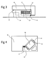
- the active element 21 extends between the back mass 20 and an upstand from the foot 24.
- a helical spring 23 between the upstand and the adjacent part of the back mass controls the pre-tension on the element 21, which may be secured to the upstand and which engages the back mass through a curved bearing surface 22.
- the solid state hinge 15 or 25 is constructed of low compliance material, for example spring steel or a high grade rigid engineering polymer, and to reduce energy losses the ratio between the thickness of the material comprising the hinge and the distance from the pivot point to the point where the hinge material is attached to the foot lever is between certain values.
- the actuator has a low profile and can still deliver a high force, only slightly less than a direct drive actuator.
- the device can be so arranged to deliver variable mechanical amplification and therefore variable force in a more controlled and predictable manner.
- Figure 3 illustrates a modification of the device shown in Figure 2 to illustrate this, and in the Figure like components are indicated by the same reference numerals.
- Variable mechanical amplification is achieved by moving the contact point 26, 27 between the actuator foot 24 and the surface being driven, towards (as at 27) and away from (as at 26) the pivot point.
- the mechanical amplification may have a value less than, equal to or greater than 1.
- the design is scalable, and can be used in a larger format to produce higher powered devices with wide frequency range and lower distortion.
- the back mass In addition to increasing bass response, increasing the back mass also increases the overall volume level produced by the device.
- the volume level can be further optimised by placing the foot 46 in the centre of the back mass 48, as may be seen from Figure 6. Again, the back mass 48 is connected to the foot 46 through a plate hinge 47, but in this embodiment, the foot 46 is an extension from the component which serves this purpose in the earlier embodiments.
- the active element 49 extends between an upstand on this component and the back mass 48, with the curved bearing surface 50 again providing a non-attached bearing contact with back mass, while a spring 51 again controls the pre-tension on the element 49.
- the overall profile and the weight of the device can be cut down by the use of a detachable mass.
- the back mass required to produce the required volume and bass level may be provided by ancillary components such as batteries, electrical circuitry and the chassis/housing of the device.
- the design of the foot is critical for the coupling of the device to the driven surface, and can to a greater or lesser degree affect the volume level and sound quality of the device.
- Such design features as profile, material and density are all factors which need to be taken into account.
Landscapes
- Engineering & Computer Science (AREA)
- Physics & Mathematics (AREA)
- Acoustics & Sound (AREA)
- Signal Processing (AREA)
- Health & Medical Sciences (AREA)
- Otolaryngology (AREA)
- Multimedia (AREA)
- Piezo-Electric Transducers For Audible Bands (AREA)
- Audible-Bandwidth Dynamoelectric Transducers Other Than Pickups (AREA)
- Apparatuses For Generation Of Mechanical Vibrations (AREA)
- Mechanical Pencils And Projecting And Retracting Systems Therefor, And Multi-System Writing Instruments (AREA)
- General Electrical Machinery Utilizing Piezoelectricity, Electrostriction Or Magnetostriction (AREA)
- Fuel-Injection Apparatus (AREA)
Priority Applications (1)
| Application Number | Priority Date | Filing Date | Title |
|---|---|---|---|
| EP06124258A EP1773097B1 (en) | 2002-12-20 | 2003-12-22 | Acoustic actuators |
Applications Claiming Priority (5)
| Application Number | Priority Date | Filing Date | Title |
|---|---|---|---|
| GB0229954 | 2002-12-20 | ||
| GB0229952A GB0229952D0 (en) | 2002-12-20 | 2002-12-20 | Magnetostrictive actuator |
| GB0229954A GB0229954D0 (en) | 2002-12-20 | 2002-12-20 | Actuator |
| GB0229952 | 2002-12-20 | ||
| PCT/GB2003/005616 WO2004057912A2 (en) | 2002-12-20 | 2003-12-22 | Acoustic actuators |
Related Child Applications (1)
| Application Number | Title | Priority Date | Filing Date |
|---|---|---|---|
| EP06124258A Division EP1773097B1 (en) | 2002-12-20 | 2003-12-22 | Acoustic actuators |
Publications (2)
| Publication Number | Publication Date |
|---|---|
| EP1576851A2 EP1576851A2 (en) | 2005-09-21 |
| EP1576851B1 true EP1576851B1 (en) | 2006-12-27 |
Family
ID=32683985
Family Applications (2)
| Application Number | Title | Priority Date | Filing Date |
|---|---|---|---|
| EP06124258A Expired - Lifetime EP1773097B1 (en) | 2002-12-20 | 2003-12-22 | Acoustic actuators |
| EP03789560A Expired - Lifetime EP1576851B1 (en) | 2002-12-20 | 2003-12-22 | Acoustic actuator |
Family Applications Before (1)
| Application Number | Title | Priority Date | Filing Date |
|---|---|---|---|
| EP06124258A Expired - Lifetime EP1773097B1 (en) | 2002-12-20 | 2003-12-22 | Acoustic actuators |
Country Status (6)
| Country | Link |
|---|---|
| US (1) | US7620193B2 (enExample) |
| EP (2) | EP1773097B1 (enExample) |
| JP (1) | JP4102904B2 (enExample) |
| AU (1) | AU2003294140A1 (enExample) |
| DE (2) | DE60310765D1 (enExample) |
| WO (1) | WO2004057912A2 (enExample) |
Families Citing this family (24)
| Publication number | Priority date | Publication date | Assignee | Title |
|---|---|---|---|---|
| WO2004057912A2 (en) | 2002-12-20 | 2004-07-08 | Newlands Technology Limited | Acoustic actuators |
| US7327637B2 (en) | 2005-02-23 | 2008-02-05 | Massachusetts Institute Of Technology | Acoustic pulse actuator |
| JP4758133B2 (ja) | 2005-04-28 | 2011-08-24 | フォスター電機株式会社 | 超磁歪スピーカ |
| GB0719246D0 (en) | 2007-10-03 | 2007-11-14 | Feonic Plc | Transducer for vibration absorbing, sensing and transmitting |
| JP4524700B2 (ja) * | 2007-11-26 | 2010-08-18 | ソニー株式会社 | スピーカ装置およびスピーカ駆動方法 |
| US8094514B2 (en) * | 2008-11-07 | 2012-01-10 | Pgs Geophysical As | Seismic vibrator array and method for using |
| US8189851B2 (en) | 2009-03-06 | 2012-05-29 | Emo Labs, Inc. | Optically clear diaphragm for an acoustic transducer and method for making same |
| ITTO20090368A1 (it) * | 2009-05-08 | 2010-11-09 | Esarc Hi Tech S R L | Dispositivo per la riproduzione del suono |
| ITTO20090369A1 (it) * | 2009-05-08 | 2010-11-09 | Esarc Hi Tech S R L | Dispositivo per la riproduzione del suono con supporto modellabile |
| ITTO20090470A1 (it) * | 2009-06-19 | 2010-12-20 | Esarc Hi Tech S R L | Dispositivo per la riproduzione del suono con attuatori acustici sovrapposti |
| US7974152B2 (en) * | 2009-06-23 | 2011-07-05 | Pgs Geophysical As | Control system for marine vibrators and seismic acquisition system using such control system |
| US8335127B2 (en) * | 2009-08-12 | 2012-12-18 | Pgs Geophysical As | Method for generating spread spectrum driver signals for a seismic vibrator array using multiple biphase modulation operations in each driver signal chip |
| GB0921195D0 (en) * | 2009-12-03 | 2010-01-20 | Feonic Plc | Audio device |
| IT1398882B1 (it) * | 2010-02-18 | 2013-03-21 | Esarc Hi Tech S R L | Dispositivo per la riproduzione del suono |
| US8446798B2 (en) | 2010-06-29 | 2013-05-21 | Pgs Geophysical As | Marine acoustic vibrator having enhanced low-frequency amplitude |
| GB201011183D0 (en) | 2010-07-02 | 2010-08-18 | Feonic Plc | Apparatus for radioating an audio signal |
| JP5680487B2 (ja) * | 2011-06-08 | 2015-03-04 | ビフレステック株式会社 | 音響装置およびその振動伝達方法 |
| US8670292B2 (en) | 2011-08-12 | 2014-03-11 | Pgs Geophysical As | Electromagnetic linear actuators for marine acoustic vibratory sources |
| WO2013131175A1 (en) * | 2012-03-08 | 2013-09-12 | Robert Katz | Audio headboard |
| WO2014144112A2 (en) | 2013-03-15 | 2014-09-18 | Emo Labs, Inc. | Acoustic transducers |
| US20150010173A1 (en) * | 2013-07-05 | 2015-01-08 | Qualcomm Incorporated | Apparatus and method for providing a frequency response for audio signals |
| AU2014375214B2 (en) * | 2013-12-30 | 2020-01-30 | Pgs Geophysical As | Control system for marine vibrators |
| US10476461B2 (en) * | 2017-12-20 | 2019-11-12 | Nvf Tech Ltd | Active distributed mode actuator |
| JP6522819B2 (ja) * | 2018-02-05 | 2019-05-29 | 京セラ株式会社 | 音発生器、音発生器用圧電振動部及び音発生システム |
Family Cites Families (10)
| Publication number | Priority date | Publication date | Assignee | Title |
|---|---|---|---|---|
| US2031789A (en) * | 1932-08-09 | 1936-02-25 | Pierce George Washington | Acoustic electric energy converter |
| US2249835A (en) * | 1937-11-11 | 1941-07-22 | Bell Telephone Labor Inc | Magnetostrictive vibrator |
| US2621260A (en) * | 1947-01-24 | 1952-12-09 | Sykes Adrian Francis | Electrical sound recording, reproducing, and like apparatus |
| US3366748A (en) | 1964-09-22 | 1968-01-30 | Artnell Company | Loudspeaker diaphragm and driver |
| US3470402A (en) * | 1967-08-25 | 1969-09-30 | Us Navy | Magnetostrictive vibration motor |
| US3697790A (en) * | 1970-12-02 | 1972-10-10 | William T Flint | Transducers having piezoelectric struts |
| US4845688A (en) | 1988-03-21 | 1989-07-04 | Image Acoustics, Inc. | Electro-mechanical transduction apparatus |
| US20010005417A1 (en) * | 1999-12-16 | 2001-06-28 | Bijan Djahansouzi | Acoustic devices |
| WO2002076141A2 (en) | 2001-03-19 | 2002-09-26 | Newlands Technology Limited | Magnetostrictive actuator |
| WO2004057912A2 (en) | 2002-12-20 | 2004-07-08 | Newlands Technology Limited | Acoustic actuators |
-
2003
- 2003-12-22 WO PCT/GB2003/005616 patent/WO2004057912A2/en not_active Ceased
- 2003-12-22 JP JP2004561675A patent/JP4102904B2/ja not_active Expired - Lifetime
- 2003-12-22 DE DE60310765T patent/DE60310765D1/de not_active Expired - Lifetime
- 2003-12-22 EP EP06124258A patent/EP1773097B1/en not_active Expired - Lifetime
- 2003-12-22 AU AU2003294140A patent/AU2003294140A1/en not_active Abandoned
- 2003-12-22 DE DE60328236T patent/DE60328236D1/de not_active Expired - Fee Related
- 2003-12-22 US US10/538,441 patent/US7620193B2/en not_active Expired - Fee Related
- 2003-12-22 EP EP03789560A patent/EP1576851B1/en not_active Expired - Lifetime
Also Published As
| Publication number | Publication date |
|---|---|
| US20060050904A1 (en) | 2006-03-09 |
| WO2004057912A2 (en) | 2004-07-08 |
| EP1576851A2 (en) | 2005-09-21 |
| EP1773097A2 (en) | 2007-04-11 |
| JP2006511135A (ja) | 2006-03-30 |
| DE60310765D1 (de) | 2007-02-08 |
| JP4102904B2 (ja) | 2008-06-18 |
| DE60328236D1 (de) | 2009-08-13 |
| EP1773097A3 (en) | 2008-01-02 |
| EP1773097B1 (en) | 2009-07-01 |
| WO2004057912A3 (en) | 2004-10-28 |
| AU2003294140A1 (en) | 2004-07-14 |
| AU2003294140A8 (en) | 2004-07-14 |
| US7620193B2 (en) | 2009-11-17 |
Similar Documents
| Publication | Publication Date | Title |
|---|---|---|
| EP1576851B1 (en) | Acoustic actuator | |
| KR100777888B1 (ko) | 트랜스듀서 | |
| US8319396B2 (en) | Piezo-electric actuator and electronic device | |
| CN1929700B (zh) | 音响信号发生用压电装置 | |
| US5736808A (en) | Piezoelectric speaker | |
| EP2235761B1 (en) | Magnetostrictive actuator | |
| EP2597894A1 (en) | Vibration device and electronic device | |
| WO2010131540A1 (ja) | 圧電アクチュエータおよび音響部品 | |
| WO2005094121A1 (ja) | 圧電音響素子、音響装置及び携帯端末装置 | |
| JP2002505822A (ja) | ラウドスピーカ組立体 | |
| US6674219B1 (en) | Piezoelectric speaker | |
| JP2007275819A (ja) | 圧電振動ユニット及び圧電式スピーカ | |
| CN101500186A (zh) | 扬声器装置 | |
| TW515220B (en) | Loudspeakers | |
| JP2006229647A (ja) | 骨伝導用音響用振動子 | |
| JP2985509B2 (ja) | 低周波水中送波器 | |
| EP2555175A1 (en) | Transducer module | |
| CN1729715B (zh) | 声致动器 | |
| KR20060097839A (ko) | 양면으로 진동하는 압전 진동자 및 이를 이용한 압전 평판스피커 | |
| US20010005417A1 (en) | Acoustic devices | |
| JP2005130149A (ja) | 音響信号発生用圧電装置 | |
| US20140376335A1 (en) | Oscillation device | |
| JP3924777B2 (ja) | フラットスピーカ | |
| CN117135551B (zh) | 压电振动模组、屏幕发声组件及电子设备 | |
| US20120321824A1 (en) | Transducer module |
Legal Events
| Date | Code | Title | Description |
|---|---|---|---|
| PUAI | Public reference made under article 153(3) epc to a published international application that has entered the european phase |
Free format text: ORIGINAL CODE: 0009012 |
|
| 17P | Request for examination filed |
Effective date: 20050701 |
|
| AK | Designated contracting states |
Kind code of ref document: A2 Designated state(s): AT BE BG CH CY CZ DE DK EE ES FI FR GB GR HU IE IT LI LU MC NL PT RO SE SI SK TR |
|
| AX | Request for extension of the european patent |
Extension state: AL LT LV MK |
|
| DAX | Request for extension of the european patent (deleted) | ||
| RBV | Designated contracting states (corrected) |
Designated state(s): DE GB IT |
|
| RIC1 | Information provided on ipc code assigned before grant |
Ipc: H04R 7/04 20060101ALI20060412BHEP Ipc: H04R 17/00 20060101ALI20060412BHEP Ipc: H04R 15/00 20060101AFI20060412BHEP |
|
| RTI1 | Title (correction) |
Free format text: ACOUSTIC ACTUATOR |
|
| GRAP | Despatch of communication of intention to grant a patent |
Free format text: ORIGINAL CODE: EPIDOSNIGR1 |
|
| GRAS | Grant fee paid |
Free format text: ORIGINAL CODE: EPIDOSNIGR3 |
|
| GRAA | (expected) grant |
Free format text: ORIGINAL CODE: 0009210 |
|
| RAP1 | Party data changed (applicant data changed or rights of an application transferred) |
Owner name: FEONIC PLC |
|
| AK | Designated contracting states |
Kind code of ref document: B1 Designated state(s): DE GB IT |
|
| REG | Reference to a national code |
Ref country code: GB Ref legal event code: FG4D |
|
| REF | Corresponds to: |
Ref document number: 60310765 Country of ref document: DE Date of ref document: 20070208 Kind code of ref document: P |
|
| PG25 | Lapsed in a contracting state [announced via postgrant information from national office to epo] |
Ref country code: DE Free format text: LAPSE BECAUSE OF FAILURE TO SUBMIT A TRANSLATION OF THE DESCRIPTION OR TO PAY THE FEE WITHIN THE PRESCRIBED TIME-LIMIT Effective date: 20070328 |
|
| PLBE | No opposition filed within time limit |
Free format text: ORIGINAL CODE: 0009261 |
|
| STAA | Information on the status of an ep patent application or granted ep patent |
Free format text: STATUS: NO OPPOSITION FILED WITHIN TIME LIMIT |
|
| 26N | No opposition filed |
Effective date: 20070928 |
|
| PGFP | Annual fee paid to national office [announced via postgrant information from national office to epo] |
Ref country code: IT Payment date: 20081223 Year of fee payment: 6 |
|
| PG25 | Lapsed in a contracting state [announced via postgrant information from national office to epo] |
Ref country code: IT Free format text: LAPSE BECAUSE OF NON-PAYMENT OF DUE FEES Effective date: 20091222 |
|
| PGFP | Annual fee paid to national office [announced via postgrant information from national office to epo] |
Ref country code: GB Payment date: 20210621 Year of fee payment: 18 |
|
| GBPC | Gb: european patent ceased through non-payment of renewal fee |
Effective date: 20211222 |
|
| PG25 | Lapsed in a contracting state [announced via postgrant information from national office to epo] |
Ref country code: GB Free format text: LAPSE BECAUSE OF NON-PAYMENT OF DUE FEES Effective date: 20211222 |