EP1576322B1 - Vorrichtung und verfahren zur reinigung von kälteanlagen - Google Patents
Vorrichtung und verfahren zur reinigung von kälteanlagen Download PDFInfo
- Publication number
- EP1576322B1 EP1576322B1 EP03796249A EP03796249A EP1576322B1 EP 1576322 B1 EP1576322 B1 EP 1576322B1 EP 03796249 A EP03796249 A EP 03796249A EP 03796249 A EP03796249 A EP 03796249A EP 1576322 B1 EP1576322 B1 EP 1576322B1
- Authority
- EP
- European Patent Office
- Prior art keywords
- chemical substance
- declogging
- cleansing
- tank
- return line
- Prior art date
- Legal status (The legal status is an assumption and is not a legal conclusion. Google has not performed a legal analysis and makes no representation as to the accuracy of the status listed.)
- Expired - Lifetime
Links
- 238000000034 method Methods 0.000 title claims abstract description 16
- 238000005057 refrigeration Methods 0.000 claims abstract description 35
- 239000000126 substance Substances 0.000 claims description 65
- 239000007789 gas Substances 0.000 claims description 15
- 230000005540 biological transmission Effects 0.000 claims description 10
- 239000012530 fluid Substances 0.000 claims description 7
- 238000004140 cleaning Methods 0.000 claims description 6
- VLKZOEOYAKHREP-UHFFFAOYSA-N n-Hexane Chemical compound CCCCCC VLKZOEOYAKHREP-UHFFFAOYSA-N 0.000 claims description 6
- CSCPPACGZOOCGX-UHFFFAOYSA-N Acetone Chemical compound CC(C)=O CSCPPACGZOOCGX-UHFFFAOYSA-N 0.000 claims description 4
- IJGRMHOSHXDMSA-UHFFFAOYSA-N Atomic nitrogen Chemical compound N#N IJGRMHOSHXDMSA-UHFFFAOYSA-N 0.000 claims description 4
- HEDRZPFGACZZDS-UHFFFAOYSA-N Chloroform Chemical compound ClC(Cl)Cl HEDRZPFGACZZDS-UHFFFAOYSA-N 0.000 claims description 4
- 238000002347 injection Methods 0.000 claims description 3
- 239000007924 injection Substances 0.000 claims description 3
- 238000011045 prefiltration Methods 0.000 claims description 3
- LFQSCWFLJHTTHZ-UHFFFAOYSA-N Ethanol Chemical compound CCO LFQSCWFLJHTTHZ-UHFFFAOYSA-N 0.000 claims description 2
- 238000001914 filtration Methods 0.000 claims description 2
- 229910052757 nitrogen Inorganic materials 0.000 claims description 2
- 238000002360 preparation method Methods 0.000 claims 1
- 239000002184 metal Substances 0.000 abstract description 3
- 239000010725 compressor oil Substances 0.000 abstract description 2
- 238000001556 precipitation Methods 0.000 abstract description 2
- 239000000463 material Substances 0.000 description 2
- 239000004809 Teflon Substances 0.000 description 1
- 229920006362 Teflon® Polymers 0.000 description 1
- 230000000903 blocking effect Effects 0.000 description 1
- 238000005260 corrosion Methods 0.000 description 1
- 230000007797 corrosion Effects 0.000 description 1
- 239000000428 dust Substances 0.000 description 1
- 230000008030 elimination Effects 0.000 description 1
- 238000003379 elimination reaction Methods 0.000 description 1
- 239000003921 oil Substances 0.000 description 1
- 239000002244 precipitate Substances 0.000 description 1
- 239000002904 solvent Substances 0.000 description 1
Images



Classifications
-
- F—MECHANICAL ENGINEERING; LIGHTING; HEATING; WEAPONS; BLASTING
- F25—REFRIGERATION OR COOLING; COMBINED HEATING AND REFRIGERATION SYSTEMS; HEAT PUMP SYSTEMS; MANUFACTURE OR STORAGE OF ICE; LIQUEFACTION SOLIDIFICATION OF GASES
- F25B—REFRIGERATION MACHINES, PLANTS OR SYSTEMS; COMBINED HEATING AND REFRIGERATION SYSTEMS; HEAT PUMP SYSTEMS
- F25B47/00—Arrangements for preventing or removing deposits or corrosion, not provided for in another subclass
-
- F—MECHANICAL ENGINEERING; LIGHTING; HEATING; WEAPONS; BLASTING
- F25—REFRIGERATION OR COOLING; COMBINED HEATING AND REFRIGERATION SYSTEMS; HEAT PUMP SYSTEMS; MANUFACTURE OR STORAGE OF ICE; LIQUEFACTION SOLIDIFICATION OF GASES
- F25B—REFRIGERATION MACHINES, PLANTS OR SYSTEMS; COMBINED HEATING AND REFRIGERATION SYSTEMS; HEAT PUMP SYSTEMS
- F25B2500/00—Problems to be solved
- F25B2500/04—Clogging
Definitions
- This invention relates to a declogging device and a declogging method used to clean the material which clogs the circulation of the fluid by blocking the refrigeration cycle in a refrigerator.
- the object of American Patent No. US6006544 is to prevent the clogging by means of the structural arrangements in the additional parts of the capillary tubes in the refrigeration cycle.
- ⁇ P 06 207765 A discloses another cleaning device.
- the object of this invention is to provide a declogging device and a declogging method used to eliminate the clogging in the refrigeration cycles.
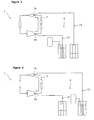
- Refrigerators generally comprise a refrigeration cycle (1) in which the refrigeration fluid circulates.
- Refrigeration cycle (1) comprises a compressor (2), a heater (3), a condenser (4), a dryer (5), an evaporator (6), a passage line (7) which transfers the refrigeration fluid from the compressor (2) to the dryer (5) and a return line (8) which transfers the refrigeration fluid back from the dryer (6) to the compressor (2).
- a declogging device (9) is used to eliminate the clogging in the refrigeration cycle (1).
- the declogging device (9) which is the subject of the invention comprises a chemical substance tank (10) where the cleansing chemical substance is filled, a pressurized gas tube (11) which provides pressurized gas to the chemical substance tank (10) and a collection tank (13) where all cleansing chemical substances are finally collected.
- the passage line (7) comprises a passage line inlet (15) close to the compressor (2) outlet and a passage line outlet (16) close to the dryer (5) inlet.
- the return line (8) comprises a return line inlet (17) close to the dryer (5) outlet and a return line outlet (18) close to the compressor (2) inlet.
- Chemical substance tank (10) comprises a transmission pipe (12) which transfers the cleansing chemical substance to the refrigeration cycle (1), a pre-filter (19) which is used to filter the foreign matters mixed in during the filling of cleansing chemical substance and an injection pipe (20) preferably made of teflon which provides the pressurized exit of the cleansing chemical substance from the chemical substance tank (10) when sufficient pressure is applied.
- the chemical substance tank (10) comprises a chemical substance heater (22) which facilitates the transfer of the chemical substance.
- the collection tank (13) comprises a collector pipe (14) which returns the cleansing chemical substance from the refrigeration cycle (1) and a final filter (21) which enables the reuse of the cleansing chemical substance after filtering the foreign matters following its circulation in the refrigeration cycle (1).
- compressor (2) and dryer (5) are detached and passage line (7) and return line (8) are split apart.
- the conveyor (12) and the collector (14) are connected to the passage line inlet (15) and the passage line outlet (16) respectively.
- the pressurized gas tube (11) is opened and the cleansing chemical substance is forwarded from the chemical substance tank (10) to the passage line (7).
- the pressure is increased and/or the cleansing chemical substance is passed in the reverse direction by connecting the transmission pipe (12) and the collector pipe (14) to the passage line outlet (16) and the passage line inlet (15) respectively.
- certain amount of the cleansing chemical substance is passed from the passage line (7) for the cleaning process. If it is not cleaned sufficiently, the cleansing chemical substance is left at the passage line (7) for a while. Until the cleansing chemical substance is returned clean, it is continued to be passed from the passage line (7).
- the transmission pipe (12) and the collector pipe (14) are connected to the return line inlet (17) and the return line outlet (18) respectively.
- the pressurized gas tube (11) is opened and the cleansing chemical substance is forwarded from the chemical substance tank (10) to the return line (8).
- the pressure is increased and/or the cleansing chemical substance is passed in the reverse direction by connecting the transmission pipe (12) and the collector pipe (14) to the return line outlet (18) and the return line inlet (17) respectively.
- certain amount of the cleansing chemical substance is passed from the return line (8) for the cleaning process. If it is not cleaned sufficiently, the cleansing chemical substance is left at the return line (8) for a while. Until the cleansing chemical substance is returned clean, it is continued to be passed from the return line (8).
- pressurized gas tube (11) As a pressurized gas tube (11) is used in the declogging device (1), oil which may be mixed with the pressurized gas obtained from the pressurized gas assembly prevents the risk of the substances such as metal dusts which may cause clogging being mixed within the system.
- a pressurized gas preferably nitrogen with low moisture which will not react with the chemical substances is used.
- chemical substances preferably Acetone, Hexane, Alcohol and Chloroform which do not react with the other materials in the environment and can clean the accumulated dirt are used as solvent.
Landscapes
- Engineering & Computer Science (AREA)
- Physics & Mathematics (AREA)
- Mechanical Engineering (AREA)
- Thermal Sciences (AREA)
- General Engineering & Computer Science (AREA)
- Cleaning By Liquid Or Steam (AREA)
- Cleaning In General (AREA)
- Lubricants (AREA)
- Studio Circuits (AREA)
- Stereo-Broadcasting Methods (AREA)
- Time-Division Multiplex Systems (AREA)
- Saccharide Compounds (AREA)
Claims (12)
- Vorrichtung zum Auflösen einer Verstopfung (9), gekennzeichnet durch einen Tank mit einer chemischen Substanz (10), der mit der chemischen Reinigungssubstanz gefüllt ist, die benutzt wird, um die Verstopfung in dem Kühlzyklus (1) zu beseitigen, wo das Kühlfluid zirkuliert, durch eine Druckgasröhre (11), die Druckgas an den Tank mit einer chemischen Substanz (10) bereitstellt, und durch einen Sammeltank (13), wo die chemischen Reinigungssubstanz nach Abschluss ihre Zyklus gesammelt wird.
- Vorrichtung zum Auflösen einer Verstopfung (9) nach Anspruch 1, gekennzeichnet durch eine Übertragungsleitung (12), die die chemische Reinigungssubstanz zu dem Kühlzyklus (1) leitet, durch einen Vorfilter (19), der benutzt wird, um Fremdstoffe zu filtern, die beim Einfüllen der chemischen Reinigungssubstanz mit dieser vermischt werden, und durch einen Tank mit einer chemischen Substanz (10), der eine Einspritzleitung (20) umfasst, die unter ausreichendem Druck einen Druckauslass der reinigenden chemischen Substanz aus dem Tank mit einer chemischern Substanz bereitstellt.
- Vorrichtung zum Auflösen einer Verstopfung (9) nach Anspruch 1 und 2, gekennzeichnet durch einen Tank mit einer chemischen Substanz (10), der ein Heizelement für eine chemische Substanz (22) aufweist, der die Übertragung der chemischen Reinigungssubstanz erleichtert.
- Vorrichtung zum Auflösen einer Verstopfung (9) nach Anspruch 1, gekennzeichnet durch einen Sammeltank (13), der eine Sammelleitung (14), die die chemische Reinigungssubstanz von dem Kühlzyklus (1) zurückführt, und einen Endfilter (21) aufweist, der die Wiederverwendung der chemischen Reinigungssubstanz durch Filtern der Fremdstoffe nach ihrer Zirkulation in dem Kühlzyklus (1) vorsieht.
- Vorrichtung zum Auflösen einer Verstopfung (9) nach Anspruch 1, gekennzeichnet durch eine Druckgasröhre (11), die Stickstoff als ein Druckgas aufweist.
- Vorrichtung zum Auflösen einer Verstopfung (9) nach Anspruch 1, gekennzeichnet durch einen Tank mit einer chemischen Substanz (10), der Azeton als eine chemische Reinigungssubstanz aufweist.
- Vorrichtung zum Auflösen einer Verstopfung (9) nach Anspruch 1, gekennzeichnet durch einen Tank mit einer chemischen Substanz (10), der Hexan als eine chemische Reinigungssubstanz aufweist.
- Vorrichtung zum Auflösen einer Verstopfung (9) nach Anspruch 1, gekennzeichnet durch einen Tank mit einer chemischen Substanz (10), der Alkohol als eine chemische Reinigungssubstanz aufweist.
- Vorrichtung zum Auflösen einer Verstopfung (9) nach Anspruch 1, gekennzeichnet durch einen Tank mit einer chemischen Substanz (10), der Chloroform als eine chemische Reinigungssubstanz aufweist.
- Verfahren zum Auflösen einer Verstopfung für eine Vorrichtung zum Auflösen einer Verstopfung (9) nach einem der vorhergehenden Ansprüche, das die folgenden Schritte umfasst: Entfernen des Kompressors (2) und des Trockners (5) von dem Kühlzyklus (1) und Abtrennen der Durchflussleitung (7) von der Rückführleitung (8) zum Vorbereiten des verstopften Kühlzyklus (1) für den Prozess zum Auflösen einer Verstopfung.
- Verfahren zum Auflösen einer Verstopfung für eine Vorrichtung zum Auflösen einer Verstopfung (9) nach Anspruch 10, das folgende Schritte umfasst: Verbinden der Übertragungsleitung (12) und der Sammelleitung (14) jeweils mit dem Einlass (15) der Durchflussleitung bzw. mit dem Auslass (16) der Durchflussleitung, um eine Verstopfung der Durchflussleitung (7) zu lösen, Übertragen der chemischen Reinigungssubstanz von dem Substanztank (10) an die Durchflussleitung (7) durch Öffnen der Gasröhre, falls sie nicht verstopft ist, Anheben des Drucks und/oder Rückleitung der chemischen Reinigungssubstanz durch Verbinden der Übertragungsleitung (12) und der Sammelleitung (14) jeweils mit dem Auslass (16) der Durchflussleitung bzw. mit dem Einlass (15) der Durchflussleitung, Strömen einer bestimmten Menge der chemischen Reinigungssubstanz von der Durchflussleitung (7) für den Reinigungsprozess, falls nicht ausreichend gereinigt wurde, vorübergehendes Zurücklassen der chemischen Reinigungssubstanz in der Durchflussleitung (7) und Fortsetzen des Strömens der chemischen Reinigungssubstanz von der Durchflussleitung (7), bis sie sauber zurückkehrt.
- Verfahren zum Auflösen einer Verstopfung für eine Vorrichtung zum Auflösen einer Verstopfung (9) nach Anspruch 10 oder 11, das folgende Schritte umfasst: Verbinden der Übertragungsleitung (12) und der Sammelleitung (14) jeweils mit dem Einlass (17) der Rückführleitung bzw. dem Auslass (18) der Rückführleitung zum Lösen einer Verstopfung der Rückführleitung (8), Übertragen der chemischen Reinigungssubtanz von dem Substanztank (10) an die Rückführleitung (8) durch Öffnen der Gasröhre, falls sie nicht verstopft ist, Anheben des Drucks und/oder Rückleitung der chemischen Reinigungssubstanz durch Verbinden der Übertragungsleitung (12) und der Sammelleitung (14) jeweils mit dem Auslass (18) der Rückführleitung bzw. dem Einlass (17) der Rückführleitung, Strömen einer bestimmten Menge der chemischen Reinigungssubstanz von der Rückführleitung (8) für den Reinigungsprozess, falls sie nicht ausreichend gereinigt ist, vorübergehendes Zurücklassen der chemischen Reinigungssubstanz in der Rückführleitung (8) und Fortsetzen des Strömens der chemischen Reinigungssubstanz von der Rückführleitung (8), bis sie sauber zurückkehrt.
Applications Claiming Priority (3)
| Application Number | Priority Date | Filing Date | Title |
|---|---|---|---|
| TR200202732 | 2002-12-26 | ||
| TR200202732 | 2002-12-26 | ||
| PCT/TR2003/000095 WO2004059225A1 (en) | 2002-12-26 | 2003-12-16 | Declogging device and declogging method |
Publications (2)
| Publication Number | Publication Date |
|---|---|
| EP1576322A1 EP1576322A1 (de) | 2005-09-21 |
| EP1576322B1 true EP1576322B1 (de) | 2006-05-31 |
Family
ID=32679812
Family Applications (1)
| Application Number | Title | Priority Date | Filing Date |
|---|---|---|---|
| EP03796249A Expired - Lifetime EP1576322B1 (de) | 2002-12-26 | 2003-12-16 | Vorrichtung und verfahren zur reinigung von kälteanlagen |
Country Status (7)
| Country | Link |
|---|---|
| US (1) | US7707839B2 (de) |
| EP (1) | EP1576322B1 (de) |
| AT (1) | ATE328255T1 (de) |
| AU (1) | AU2003298497A1 (de) |
| DE (1) | DE60305735T2 (de) |
| TR (1) | TR200502311T1 (de) |
| WO (1) | WO2004059225A1 (de) |
Families Citing this family (3)
| Publication number | Priority date | Publication date | Assignee | Title |
|---|---|---|---|---|
| US20120031135A1 (en) * | 2009-04-09 | 2012-02-09 | MAJA-MASCHINENFABRILK HERMANN SCHILL GmbH &Co. KG | Apparatus for Producing Flake Ice and Method for Cleaning, Descaling and/or Disinfecting an Apparatus for Producing Flake Ice |
| WO2014180505A1 (en) | 2013-05-08 | 2014-11-13 | Arcelik Anonim Sirketi | Apparatus for detecting leakage in a cooling system and method of detecting leakage |
| US11029063B2 (en) * | 2017-09-14 | 2021-06-08 | Ingersoll-Rand Industrial U.S.. Inc. | Compressor system having a refrigerated dryer |
Family Cites Families (18)
| Publication number | Priority date | Publication date | Assignee | Title |
|---|---|---|---|---|
| US3295538A (en) * | 1963-10-18 | 1967-01-03 | Jr Clarence B Williams | Refrigeration system cleaner |
| US3503221A (en) | 1968-06-17 | 1970-03-31 | Frank C Martin | Dehydration,cleaning and sterilization method and apparatus |
| US4887435A (en) | 1988-06-23 | 1989-12-19 | Anderson Jr David W | Refrigeration cleaning and flushing system |
| US4934390A (en) * | 1988-12-15 | 1990-06-19 | Thermo King Corporation | Methods and apparatus for cleaning refrigeration equipment |
| US5318700A (en) * | 1992-08-07 | 1994-06-07 | Wynn Oil Company | Engine and radiator coolant treatment and handling, enabling coolant reuse |
| JPH06207765A (ja) | 1993-01-11 | 1994-07-26 | Chino Corp | 洗浄装置 |
| JP2593403B2 (ja) | 1993-11-02 | 1997-03-26 | ジャテック株式会社 | 冷凍または冷却サイクルの洗浄装置 |
| US5375426A (en) * | 1993-12-30 | 1994-12-27 | Air Liquide America Corporation | Process to clean a lubricated vapor compression refrigeration system by using carbon dioxide |
| US5544494A (en) * | 1994-12-27 | 1996-08-13 | Spx Corporation | Method and apparatus for refrigerant purification |
| US5544492A (en) * | 1995-06-05 | 1996-08-13 | Spx Corporation | Refrigerant handling system and method with air purge and multiple refrigerant capabilities |
| US5632153A (en) * | 1995-08-24 | 1997-05-27 | Foodbrands America, Incorporated | System and process for cleansing brine in a food-chilling circuit |
| US6164080A (en) * | 1998-08-12 | 2000-12-26 | Hudson Technologies, Inc. | Apparatus and method for flushing a refrigeration system |
| US6260390B1 (en) * | 1999-03-10 | 2001-07-17 | Sail Star Limited | Dry cleaning process using rotating basket agitation |
| JP3354124B2 (ja) | 1999-12-21 | 2002-12-09 | 泰治 黒河 | 冷凍サイクル等の洗浄装置 |
| JP3497432B2 (ja) | 1999-12-27 | 2004-02-16 | 文博 太田 | 冷凍・冷暖房機の配管洗浄装置 |
| US6203623B1 (en) * | 1999-12-28 | 2001-03-20 | Ball Semiconductor, Inc. | Aerosol assisted chemical cleaning method |
| US6616771B2 (en) * | 2001-11-30 | 2003-09-09 | Forhealth Technologies, Inc. | Method and system for cleaning and reusing a cannula |
| US6619051B1 (en) * | 2002-07-12 | 2003-09-16 | Ecolab Inc. | Integrated cleaning and sanitizing system and method for ice machines |
-
2003
- 2003-12-16 DE DE60305735T patent/DE60305735T2/de not_active Expired - Lifetime
- 2003-12-16 WO PCT/TR2003/000095 patent/WO2004059225A1/en not_active Ceased
- 2003-12-16 AT AT03796249T patent/ATE328255T1/de not_active IP Right Cessation
- 2003-12-16 EP EP03796249A patent/EP1576322B1/de not_active Expired - Lifetime
- 2003-12-16 US US10/540,430 patent/US7707839B2/en not_active Expired - Fee Related
- 2003-12-16 TR TR2005/02311T patent/TR200502311T1/xx unknown
- 2003-12-16 AU AU2003298497A patent/AU2003298497A1/en not_active Abandoned
Also Published As
| Publication number | Publication date |
|---|---|
| US7707839B2 (en) | 2010-05-04 |
| US20060196209A1 (en) | 2006-09-07 |
| EP1576322A1 (de) | 2005-09-21 |
| AU2003298497A1 (en) | 2004-07-22 |
| TR200502311T1 (tr) | 2005-09-21 |
| ATE328255T1 (de) | 2006-06-15 |
| WO2004059225A1 (en) | 2004-07-15 |
| DE60305735T2 (de) | 2007-05-31 |
| DE60305735D1 (de) | 2006-07-06 |
Similar Documents
| Publication | Publication Date | Title |
|---|---|---|
| EP0174554B1 (de) | Wärmeaustauscher zum Übertragen von Wärme aus Abwasser | |
| US3212289A (en) | Combination accumulator and receiver | |
| US5575833A (en) | Refrigerant recycling system and apparatus | |
| CN201255547Y (zh) | 冷媒回收机中的空调管路清洗装置 | |
| KR20180102536A (ko) | 디젤 배기 미립자 수집기용 청소 시스템 | |
| US5220810A (en) | Refrigerant recovery system with flush mode and associated flushing adapter apparatus | |
| EP1576322B1 (de) | Vorrichtung und verfahren zur reinigung von kälteanlagen | |
| US5379605A (en) | Method for cleaning air conditioning system | |
| US5117641A (en) | Refrigerant recovery system with flush mode | |
| US3974659A (en) | Oil sampling and charging method and apparatus for refrigeration systems | |
| KR100537943B1 (ko) | 볼순환펌프를 이용한 열교환기튜브 자동세정장치 | |
| US3564863A (en) | Refrigeration system purifier | |
| DE102008031834A1 (de) | Vorrichtung zum Abscheiden von Partikeln in einem Kühlkreislauf bei der Profilextrusion | |
| WO1996012921A1 (en) | Air conditioner and method of controlling washing operation thereof | |
| KR100607685B1 (ko) | 펌프이용 열교환기튜브 자동세정장치 | |
| KR200227922Y1 (ko) | 콘덴서 내의 유체수송관 세정장치 | |
| CN220580142U (zh) | 一种市政防堵塞排水管道 | |
| WO2020058984A1 (en) | A condenser cleaning system | |
| KR100389723B1 (ko) | 콘덴서 내의 유체수송관 세정장치 | |
| CN110195909B (zh) | 一种基于大数据分析的故障预警系统 | |
| CN2522850Y (zh) | 汽车自动变速箱内置滤清器清洁度测试装置 | |
| CN2438497Y (zh) | 两次过滤的精细过滤器 | |
| DE3402286A1 (de) | Waermetauscher | |
| JP2022024587A (ja) | ストレーナ洗浄システム | |
| JP4170069B2 (ja) | 空調装置および空調用ストレーナ装置 |
Legal Events
| Date | Code | Title | Description |
|---|---|---|---|
| PUAI | Public reference made under article 153(3) epc to a published international application that has entered the european phase |
Free format text: ORIGINAL CODE: 0009012 |
|
| 17P | Request for examination filed |
Effective date: 20050624 |
|
| AK | Designated contracting states |
Kind code of ref document: A1 Designated state(s): AT BE BG CH CY CZ DE DK EE ES FI FR GB GR HU IE IT LI LU MC NL PT RO SE SI SK TR |
|
| AX | Request for extension of the european patent |
Extension state: AL LT LV MK |
|
| GRAP | Despatch of communication of intention to grant a patent |
Free format text: ORIGINAL CODE: EPIDOSNIGR1 |
|
| DAX | Request for extension of the european patent (deleted) | ||
| GRAS | Grant fee paid |
Free format text: ORIGINAL CODE: EPIDOSNIGR3 |
|
| GRAA | (expected) grant |
Free format text: ORIGINAL CODE: 0009210 |
|
| AK | Designated contracting states |
Kind code of ref document: B1 Designated state(s): AT BE BG CH CY CZ DE DK EE ES FI FR GB GR HU IE IT LI LU MC NL PT RO SE SI SK TR |
|
| PG25 | Lapsed in a contracting state [announced via postgrant information from national office to epo] |
Ref country code: CZ Free format text: LAPSE BECAUSE OF FAILURE TO SUBMIT A TRANSLATION OF THE DESCRIPTION OR TO PAY THE FEE WITHIN THE PRESCRIBED TIME-LIMIT Effective date: 20060531 Ref country code: IT Free format text: LAPSE BECAUSE OF FAILURE TO SUBMIT A TRANSLATION OF THE DESCRIPTION OR TO PAY THE FEE WITHIN THE PRESCRIBED TIME-LIMIT;WARNING: LAPSES OF ITALIAN PATENTS WITH EFFECTIVE DATE BEFORE 2007 MAY HAVE OCCURRED AT ANY TIME BEFORE 2007. THE CORRECT EFFECTIVE DATE MAY BE DIFFERENT FROM THE ONE RECORDED. Effective date: 20060531 Ref country code: RO Free format text: LAPSE BECAUSE OF FAILURE TO SUBMIT A TRANSLATION OF THE DESCRIPTION OR TO PAY THE FEE WITHIN THE PRESCRIBED TIME-LIMIT Effective date: 20060531 Ref country code: AT Free format text: LAPSE BECAUSE OF FAILURE TO SUBMIT A TRANSLATION OF THE DESCRIPTION OR TO PAY THE FEE WITHIN THE PRESCRIBED TIME-LIMIT Effective date: 20060531 Ref country code: SI Free format text: LAPSE BECAUSE OF FAILURE TO SUBMIT A TRANSLATION OF THE DESCRIPTION OR TO PAY THE FEE WITHIN THE PRESCRIBED TIME-LIMIT Effective date: 20060531 Ref country code: NL Free format text: LAPSE BECAUSE OF FAILURE TO SUBMIT A TRANSLATION OF THE DESCRIPTION OR TO PAY THE FEE WITHIN THE PRESCRIBED TIME-LIMIT Effective date: 20060531 Ref country code: FI Free format text: LAPSE BECAUSE OF FAILURE TO SUBMIT A TRANSLATION OF THE DESCRIPTION OR TO PAY THE FEE WITHIN THE PRESCRIBED TIME-LIMIT Effective date: 20060531 Ref country code: BE Free format text: LAPSE BECAUSE OF FAILURE TO SUBMIT A TRANSLATION OF THE DESCRIPTION OR TO PAY THE FEE WITHIN THE PRESCRIBED TIME-LIMIT Effective date: 20060531 Ref country code: CH Free format text: LAPSE BECAUSE OF FAILURE TO SUBMIT A TRANSLATION OF THE DESCRIPTION OR TO PAY THE FEE WITHIN THE PRESCRIBED TIME-LIMIT Effective date: 20060531 Ref country code: LI Free format text: LAPSE BECAUSE OF FAILURE TO SUBMIT A TRANSLATION OF THE DESCRIPTION OR TO PAY THE FEE WITHIN THE PRESCRIBED TIME-LIMIT Effective date: 20060531 Ref country code: SK Free format text: LAPSE BECAUSE OF FAILURE TO SUBMIT A TRANSLATION OF THE DESCRIPTION OR TO PAY THE FEE WITHIN THE PRESCRIBED TIME-LIMIT Effective date: 20060531 |
|
| REG | Reference to a national code |
Ref country code: GB Ref legal event code: FG4D Ref country code: CH Ref legal event code: EP |
|
| REG | Reference to a national code |
Ref country code: IE Ref legal event code: FG4D |
|
| REF | Corresponds to: |
Ref document number: 60305735 Country of ref document: DE Date of ref document: 20060706 Kind code of ref document: P |
|
| PG25 | Lapsed in a contracting state [announced via postgrant information from national office to epo] |
Ref country code: DK Free format text: LAPSE BECAUSE OF FAILURE TO SUBMIT A TRANSLATION OF THE DESCRIPTION OR TO PAY THE FEE WITHIN THE PRESCRIBED TIME-LIMIT Effective date: 20060831 Ref country code: SE Free format text: LAPSE BECAUSE OF FAILURE TO SUBMIT A TRANSLATION OF THE DESCRIPTION OR TO PAY THE FEE WITHIN THE PRESCRIBED TIME-LIMIT Effective date: 20060831 |
|
| PG25 | Lapsed in a contracting state [announced via postgrant information from national office to epo] |
Ref country code: ES Free format text: LAPSE BECAUSE OF FAILURE TO SUBMIT A TRANSLATION OF THE DESCRIPTION OR TO PAY THE FEE WITHIN THE PRESCRIBED TIME-LIMIT Effective date: 20060911 |
|
| PG25 | Lapsed in a contracting state [announced via postgrant information from national office to epo] |
Ref country code: PT Free format text: LAPSE BECAUSE OF FAILURE TO SUBMIT A TRANSLATION OF THE DESCRIPTION OR TO PAY THE FEE WITHIN THE PRESCRIBED TIME-LIMIT Effective date: 20061031 |
|
| NLV1 | Nl: lapsed or annulled due to failure to fulfill the requirements of art. 29p and 29m of the patents act | ||
| REG | Reference to a national code |
Ref country code: CH Ref legal event code: PL |
|
| PG25 | Lapsed in a contracting state [announced via postgrant information from national office to epo] |
Ref country code: IE Free format text: LAPSE BECAUSE OF NON-PAYMENT OF DUE FEES Effective date: 20061218 |
|
| PG25 | Lapsed in a contracting state [announced via postgrant information from national office to epo] |
Ref country code: MC Free format text: LAPSE BECAUSE OF NON-PAYMENT OF DUE FEES Effective date: 20061231 |
|
| PLBE | No opposition filed within time limit |
Free format text: ORIGINAL CODE: 0009261 |
|
| STAA | Information on the status of an ep patent application or granted ep patent |
Free format text: STATUS: NO OPPOSITION FILED WITHIN TIME LIMIT |
|
| EN | Fr: translation not filed | ||
| 26N | No opposition filed |
Effective date: 20070301 |
|
| PG25 | Lapsed in a contracting state [announced via postgrant information from national office to epo] |
Ref country code: FR Free format text: LAPSE BECAUSE OF FAILURE TO SUBMIT A TRANSLATION OF THE DESCRIPTION OR TO PAY THE FEE WITHIN THE PRESCRIBED TIME-LIMIT Effective date: 20070309 Ref country code: GR Free format text: LAPSE BECAUSE OF FAILURE TO SUBMIT A TRANSLATION OF THE DESCRIPTION OR TO PAY THE FEE WITHIN THE PRESCRIBED TIME-LIMIT Effective date: 20060901 |
|
| PG25 | Lapsed in a contracting state [announced via postgrant information from national office to epo] |
Ref country code: EE Free format text: LAPSE BECAUSE OF FAILURE TO SUBMIT A TRANSLATION OF THE DESCRIPTION OR TO PAY THE FEE WITHIN THE PRESCRIBED TIME-LIMIT Effective date: 20060531 Ref country code: BG Free format text: LAPSE BECAUSE OF FAILURE TO SUBMIT A TRANSLATION OF THE DESCRIPTION OR TO PAY THE FEE WITHIN THE PRESCRIBED TIME-LIMIT Effective date: 20060831 |
|
| PG25 | Lapsed in a contracting state [announced via postgrant information from national office to epo] |
Ref country code: HU Free format text: LAPSE BECAUSE OF FAILURE TO SUBMIT A TRANSLATION OF THE DESCRIPTION OR TO PAY THE FEE WITHIN THE PRESCRIBED TIME-LIMIT Effective date: 20061201 Ref country code: LU Free format text: LAPSE BECAUSE OF NON-PAYMENT OF DUE FEES Effective date: 20061216 |
|
| PG25 | Lapsed in a contracting state [announced via postgrant information from national office to epo] |
Ref country code: FR Free format text: LAPSE BECAUSE OF FAILURE TO SUBMIT A TRANSLATION OF THE DESCRIPTION OR TO PAY THE FEE WITHIN THE PRESCRIBED TIME-LIMIT Effective date: 20060531 Ref country code: CY Free format text: LAPSE BECAUSE OF FAILURE TO SUBMIT A TRANSLATION OF THE DESCRIPTION OR TO PAY THE FEE WITHIN THE PRESCRIBED TIME-LIMIT Effective date: 20060531 |
|
| PGFP | Annual fee paid to national office [announced via postgrant information from national office to epo] |
Ref country code: TR Payment date: 20141021 Year of fee payment: 12 Ref country code: DE Payment date: 20141211 Year of fee payment: 12 Ref country code: GB Payment date: 20141219 Year of fee payment: 12 |
|
| REG | Reference to a national code |
Ref country code: DE Ref legal event code: R119 Ref document number: 60305735 Country of ref document: DE |
|
| GBPC | Gb: european patent ceased through non-payment of renewal fee |
Effective date: 20151216 |
|
| PG25 | Lapsed in a contracting state [announced via postgrant information from national office to epo] |
Ref country code: GB Free format text: LAPSE BECAUSE OF NON-PAYMENT OF DUE FEES Effective date: 20151216 Ref country code: DE Free format text: LAPSE BECAUSE OF NON-PAYMENT OF DUE FEES Effective date: 20160701 |
|
| PG25 | Lapsed in a contracting state [announced via postgrant information from national office to epo] |
Ref country code: TR Free format text: LAPSE BECAUSE OF NON-PAYMENT OF DUE FEES Effective date: 20151216 |