EP1576248B1 - Verrou a reservoir reagissant a un changement de pression - Google Patents
Verrou a reservoir reagissant a un changement de pression Download PDFInfo
- Publication number
- EP1576248B1 EP1576248B1 EP03751775.2A EP03751775A EP1576248B1 EP 1576248 B1 EP1576248 B1 EP 1576248B1 EP 03751775 A EP03751775 A EP 03751775A EP 1576248 B1 EP1576248 B1 EP 1576248B1
- Authority
- EP
- European Patent Office
- Prior art keywords
- pressure
- bolt
- latch mechanism
- panel
- pressure responsive
- Prior art date
- Legal status (The legal status is an assumption and is not a legal conclusion. Google has not performed a legal analysis and makes no representation as to the accuracy of the status listed.)
- Expired - Lifetime
Links
- 230000007246 mechanism Effects 0.000 claims description 92
- 230000000717 retained effect Effects 0.000 claims description 31
- 230000004044 response Effects 0.000 claims description 10
- 238000006073 displacement reaction Methods 0.000 claims description 5
- 238000000034 method Methods 0.000 claims description 5
- 230000004888 barrier function Effects 0.000 description 26
- 230000008859 change Effects 0.000 description 17
- 238000013022 venting Methods 0.000 description 10
- 230000006378 damage Effects 0.000 description 6
- 230000006837 decompression Effects 0.000 description 6
- 239000012530 fluid Substances 0.000 description 3
- 230000013011 mating Effects 0.000 description 3
- 230000036316 preload Effects 0.000 description 3
- 238000007789 sealing Methods 0.000 description 3
- 208000027418 Wounds and injury Diseases 0.000 description 2
- 230000004913 activation Effects 0.000 description 2
- 238000010276 construction Methods 0.000 description 2
- 230000000694 effects Effects 0.000 description 2
- 208000014674 injury Diseases 0.000 description 2
- 239000000463 material Substances 0.000 description 2
- 239000002245 particle Substances 0.000 description 2
- 230000009471 action Effects 0.000 description 1
- 230000002547 anomalous effect Effects 0.000 description 1
- 230000008901 benefit Effects 0.000 description 1
- 230000006835 compression Effects 0.000 description 1
- 238000007906 compression Methods 0.000 description 1
- 238000013461 design Methods 0.000 description 1
- 230000001066 destructive effect Effects 0.000 description 1
- 230000001627 detrimental effect Effects 0.000 description 1
- 230000003292 diminished effect Effects 0.000 description 1
- 239000000428 dust Substances 0.000 description 1
- 230000007613 environmental effect Effects 0.000 description 1
- 238000001914 filtration Methods 0.000 description 1
- 239000012634 fragment Substances 0.000 description 1
- 238000012986 modification Methods 0.000 description 1
- 230000004048 modification Effects 0.000 description 1
- 230000002028 premature Effects 0.000 description 1
- 230000004043 responsiveness Effects 0.000 description 1
- 230000000452 restraining effect Effects 0.000 description 1
- 238000009420 retrofitting Methods 0.000 description 1
- 238000012552 review Methods 0.000 description 1
- 238000000926 separation method Methods 0.000 description 1
- 230000001960 triggered effect Effects 0.000 description 1
Images


Classifications
-
- B—PERFORMING OPERATIONS; TRANSPORTING
- B64—AIRCRAFT; AVIATION; COSMONAUTICS
- B64C—AEROPLANES; HELICOPTERS
- B64C1/00—Fuselages; Constructional features common to fuselages, wings, stabilising surfaces or the like
- B64C1/14—Windows; Doors; Hatch covers or access panels; Surrounding frame structures; Canopies; Windscreens accessories therefor, e.g. pressure sensors, water deflectors, hinges, seals, handles, latches, windscreen wipers
- B64C1/1407—Doors; surrounding frames
- B64C1/1469—Doors between cockpit and cabin
-
- B—PERFORMING OPERATIONS; TRANSPORTING
- B64—AIRCRAFT; AVIATION; COSMONAUTICS
- B64D—EQUIPMENT FOR FITTING IN OR TO AIRCRAFT; FLIGHT SUITS; PARACHUTES; ARRANGEMENT OR MOUNTING OF POWER PLANTS OR PROPULSION TRANSMISSIONS IN AIRCRAFT
- B64D45/00—Aircraft indicators or protectors not otherwise provided for
- B64D45/0015—Devices specially adapted for the protection against criminal attack, e.g. anti-hijacking systems
- B64D45/0021—Devices specially adapted for the protection against criminal attack, e.g. anti-hijacking systems means for restricting access to flight deck
- B64D45/0028—Devices specially adapted for the protection against criminal attack, e.g. anti-hijacking systems means for restricting access to flight deck doors or door arrangements specially adapted to restrict unauthorized access
-
- E—FIXED CONSTRUCTIONS
- E05—LOCKS; KEYS; WINDOW OR DOOR FITTINGS; SAFES
- E05B—LOCKS; ACCESSORIES THEREFOR; HANDCUFFS
- E05B51/00—Operating or controlling locks or other fastening devices by other non-mechanical means
- E05B51/02—Operating or controlling locks or other fastening devices by other non-mechanical means by pneumatic or hydraulic means
- E05B51/023—Operating or controlling locks or other fastening devices by other non-mechanical means by pneumatic or hydraulic means actuated in response to external pressure, blast or explosion
-
- B—PERFORMING OPERATIONS; TRANSPORTING
- B64—AIRCRAFT; AVIATION; COSMONAUTICS
- B64C—AEROPLANES; HELICOPTERS
- B64C1/00—Fuselages; Constructional features common to fuselages, wings, stabilising surfaces or the like
- B64C2001/009—Fuselages; Constructional features common to fuselages, wings, stabilising surfaces or the like comprising decompression panels or valves for pressure equalisation in fuselages or floors
Definitions
- the present disclosure relates generally to the field of latch mechanisms and particularly to a latch mechanism utilized in an aircraft. More particularly, the present disclosure relates to a latch mechanism which operates in response to a pressure change on at least one side of a barrier in an aircraft to allow a panel associated with the barrier to release upon a given set or range of pressure conditions.
- a variety of latch mechanisms have been developed to maintain panels, doors and other structures in a closed position.
- the reference to panels, doors and other structures relates to the use of latch mechanisms to retain a first body, such as a panel relative to a second body, such as a frame.
- a panel includes one portion which might be rotatably hinged or otherwise movably retained on a corresponding structure such as a frame.
- the panel serves to close or cover at least a portion of an opening defined by the frame for a variety of purposes including providing a barrier to prevent passage through the opening.
- blowout latch mechanisms have been developed to facilitate the movement or "blowout” of a panel relative to the frame.
- blowout latch mechanisms have been developed by Hartwell Corporation, assignee of the present disclosure, to facilitate disengagement of a panel from a frame or other structure under a set or range of "blowout” conditions. For example, if a pressure differential develops on opposite sides of a barrier or within an area at least partially housed or contained by the panel, the pressure differential will rise to a point where the panel may be forcibly removed, disengaged or "blown out” from the frame by forces associated with the pressure differential. Under these conditions, it is desirable to set the blowout force at a desired level or range so that premature disengagement of the panel from the primary structure does not occur. In this situation, the blow out load level can be set so that a predetermined pressure differential disengages the panel from the primary structure to protect and preserve the integrity of the frame and any related structures and devices.
- a panel in a closed position under one level or range of pressure conditions yet release the panel under a second range or set of conditions.
- Such level or range may or may not overlap or may be discrete ranges or, in fact, points.
- the panel in such a situation generally is in an environment where the pressure on either side of the panel is generally equalized.
- the panel may include a sealing structure to prevent the unwanted or abrupt passage of air there through. However, the pressure on either side of the panel is generally equal.
- a panel in a pressurized cabin such as in an aircraft.
- the panel is employed as a barrier to separate the flight crew, passengers and/or cargo into discrete areas.
- Such a panel may be used between the flight deck and passenger compartment as well as perhaps between the passenger compartment and corresponding storage area which is not occupied by passengers.
- Such a pressure differential may occur in the case where cabin pressure drops in the cargo compartment due to a leak or other loss of pressure. Under these circumstances, it might be desirable to allow the cabin pressure to generally equalize to avoid or minimize damage which might result from the pressure differential.
- the panel to the flight deck generally is maintained in a closed and latched position while in flight to maintain privacy and security of the flight crew. This prevents the passage of passengers or terrorists into the flight deck area. Increased latching strength is required in order to prevent a passenger or terrorist from forcibly opening the panel.
- the panel will open thereby providing increased safety.
- the pressure differential occurs as a result of loss of pressure in the flight deck, the panel will be allowed to disengage the frame, yet be retained thereon, to provide pressure equalization to prevent injury to the flight crew and equipment.
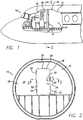
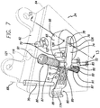
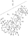
- Fig. 1 shows a fragment of a front section of an aircraft 14 in which a portion of the outside of the aircraft 14 has been broken away to illustrate a barrier 16.
- the barrier 16 divides an internal compartment 17 to separate a flight deck or cockpit area 18 from a passenger area 19.
- the present disclosure helps to prevent unpermitted or unauthorized access from the passenger compartment 19 to the cockpit 18.
- the disclosure allows automatic opening of the barrier 16 in the event of depressurization or decompression in either the cockpit 18 or passenger compartment 19.
- Fig. 2 provides a general diagrammatic illustration taken along line 2-2 in Fig. 1 showing a view from the cockpit area 18 facing the barrier 16.
- latch mechanism 24 includes a first latching portion 20 and a second receiving portion 22.
- first latching portion 20 is responsive to pressure differentials or pressure change in the cockpit 18 or the passenger area 19, as described further herein.
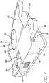
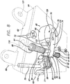
- the door or panel assembly 32 includes a frame structure 38 and a panel 40.
- the panel 40 includes a free end 42 and a movably retained end 44. Depending on the design of the panel, the panel 40 may swing inwardly towards the cockpit 18 or outwardly toward the passenger area 19, or swing both directions. The movement of the panel 40 depends upon the retaining structure 50, such as a hinge structure, which attaches the retained end 44 to a receiver portion 51 of the frame structure 52.
- the free end 42 of the door panel 40 moves relative to the retained end 44 by way of the retaining means 50 to move the panel relative to the receiver portion 51 of the frame structure 52.
- the panel 40 may not include an entire door structure and may instead be a panel retained on and as part of the door structure such that the door structure may actually define a portion of a frame relative to the panel in this example.
- the first and second portions 20, 22 are attached to respective, generally proximate areas on the frame 38 and panel 40.
- the first and second portions, 20, 22 make up the latch mechanism 24. It should be understood, however, that it is within the scope of the disclosure to exchange the functions of first portion 20 and second portion 22 such that first portion 20 is the retaining portion and second portion 22 is the latching portion. Additionally, it should be understood that the latch mechanism 24 may be contained in one of the portions 22, 20 such that the structure extends from the latch mechanism 24 and would engage the corresponding oppositely positioned structure. For example, in a situation in which the latch mechanism 24 is in the form of a latch assembly position such as first portion 20 in Fig. 2 .
- the latch mechanism (24) may include a bolt 60 or other extending portion which engages the panel 40. In this situation there may not be a separate component into which the bolt 60 is received. It is fully within the scope of the present disclosure that the latch mechanism 24 may be a single component with a portion to engage or otherwise retain the panel or door 40 to which a latch mechanism 24 is attached.
- the latch mechanism 24 illustratively functions to provide a resistance force which resists separation of the panel 40 from the corresponding frame 38.
- the panel 40 is retained or locked in position until other pressure related conditions are met.
- the retaining force is generally illustrated as a mechanical arrangement whereby one mechanism engages a corresponding area to prevent dislodgement of the panel 40 from the frame 38.
- portions 20, 22 making up the latch mechanism 24 may have a magnetic force such that the magnetic force resists displacement of the door panel 40 relative to the frame 38.
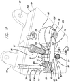
- first portion 20 of latch mechanism 24 includes a bolt 60 which engages a corresponding second receiving portion 22 coupled to the panel 40, thereby preventing disengagement of the panel 40 from the frame 38.
- the latch mechanism 24, such as first portion 20, comprises a housing 62, a cover 64, and a pressure responsive device 66 shown herein with an air cylinder 65 and a reservoir 93 configured to lock or unlock bolt 60.
- the cover 64 is mounted against the barrier 16 and may be provided in the form of an armor material to resist damage to the latch mechanism from a gun shot or other destructive force.
- bolt 60 pivots about an axis 68 defined by rod 70 which is positioned in bore 119 and retained therein by set screw 121.
- bolt 60 could be moved laterally relative to housing 62 between an extended position and a retracted position. This movement could also be controlled by a piston, for example, with a piston that is mounted transverse to the illustrative pressure responsive device 66.
- the pressure responsive device 66 detects a decrease in pressure on one side of the panel.
- bolt 60 can be moved between a locked position as shown in Fig. 3 and an unlocked or released position, shown in Fig. 4 .
- bolt 60 In the unlocked position, bolt 60 is rotated or disengaged such that panel 40 may be moved relative to frame structure 38.
- the receiving portion 22 may be in the form of a strike plate as well as a strike pocket or other bolt retaining device.
- the strike plate or bolt pocket may be attached to the panel to provide secure engagement of the bolt 60 therewith.
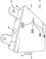
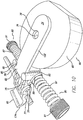
- Fig. 5 is a rear view of first portion 20, showing cover 64 fastened to housing 62 with fasteners 72.
- first portion 20 Internal elements of first portion 20 can be seen in Figs. 6-12 , wherein cover 64 has been removed.
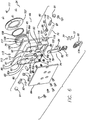
- bolt 60 is pivotably coupled to a first end of slider 74.
- the slider 74 with a link 75 retained therebetween with link pins 77, is configured to slidably move and articulate relative to pressure response device 66.
- pressure responsive device 66 illustratively includes a pneumatic piston (see, Fig. 13 ), however, it is within the scope of the disclosure for pressure responsive device 66 to comprise any type of pressure-actuated switch, for example, an electrically powered solenoid.
- Air cylinder 65 of the pressure responsive device 66 illustratively moves a bolt engaging device 76 in the form of a shear pin 76 between a position in which it engages the slider 74 (see, Fig. 7 ) and a disengaged (See, Fig. 9 ) position in which it is disengaged from the slider 74.
- shear pin 76 In the engaged position, shear pin 76 is operatively engaged with the slider 74 to resist movement of the slider 74.
- the pin 76 mates with or otherwise engages a receiving structure 78, shown in the form of an aperture 78 formed in slider 74 such that slider 74 cannot move relative to pressure responsive device 66.
- retainer assembly 80 When the pressure responsive device 66 is triggered to withdraw shear pin 76 from a mating relationship with aperture 78, slider 74 is retained in position by retainer assembly 80.
- the retainer assembly 80 is in the form of a spring biased retainer which biased against bolt-end 82 of slider 74.
- Slider 74 also has recesses 84, as can be seen in Figs. 6 and 8 , which receive a roller 85 biased by spring 87 held between a detent plug 89 and a detent set screw 91 and cooperate to retain slider 74 (and therefore bolt 60) in the retained, locked position until the biasing force provided by the retainer assembly 80 is overcome.
- the detent plug 89 includes a post 110 which is received in a bore 112 defined by the spring 87.
- a face of the detent plug 89 includes a recess 114.
- the recess 114 is generally oriented to cradle the outside surface of the detent roller 85 to enhance the engagement operation of the retainer assembly 80.
- the set screw 91 is threaded and engages correspondingly threaded bore 116 in the housing 62. The set screw 91 can be operated to adjust the pre-load of the spring 87 on the rollers 85.
- the pre-load is adjusted by engaging the set screw 91 against the spring 87 and inwardly threading the set screw 91 until a desired pre-load force is exerted by the spring from a now compressed in the bore 116 against the detent plug 89 and corresponding detent roller 85.
- the detent rollers 85 are axially inserted into corresponding receptacles 118 in the housing.
- the receptacles are slightly elongated relative to the bore 116 to provide some degree of movement of the rollers 85 relative to the slider 74.
- the slider 74 moves generally axially outwardly toward the bolt 60 end of the housing 62 along the slider channel 120.
- the recesses 84 on the sides of the slider 74 disengage the rollers 85.
- the rollers 85 are slightly compressed against the spring 87 and are displaced inwardly into the receptacles 118.
- the rollers 85 are retained in this compressed position as a result of engaging the slider sides 122 while the slider 74 is extended in the channel 120.
- the latch mechanism 24 includes structures which function to vent on only one side of the barrier 16. In this regard, there is no need to provide a venting passage between the cockpit 18 and the passenger compartment 19. This overcomes the problem of some situations in which venting to the passenger compartment 19 could be detrimental. While there are situations which benefit from venting on both sides of the compartments 18, 19, it may desirable to prevent interference or disruption of the latch mechanism 24 by venting on only one side of the barrier 16.
- venting from only the cockpit side 18 is desirable.
- venting may only be desirable on the cockpit side.
- This construction provides the blow-out feature of the latch 24 but eliminates the opportunity for a terrorist to interfere or otherwise override the venting system which might occur by venting to both sides of the barrier 16.
- Chambers 83, 86 are provided in the housing 62 collectively defining a reservoir chamber 93 which is at least generally isolated from the cockpit ambient atmosphere in this example.
- the reservoir chamber 93 provides a reference pressure relative to and communicating with the air cylinder 65.
- the air cylinder 65 includes one side that communicates with the reservoir 93 and another side which communicates with the ambient atmosphere or cockpit atmosphere.
- the air cylinder 66 communicates with the chambers 83, 86, the reservoir chamber 93, by means of openings or apertures 126 communicating with passages 90, 92.
- This referential volume of air in the reservoir chamber 93 does not change in pressure rapidly.
- an exposed or exterior side 61 of the housing 62 includes the outside surface 88 of the air cylinder 65.
- this side 88 of the air cylinder 65 communicates with the cockpit atmosphere. As such, a rapid change in the pressure in the cockpit or ambient atmosphere will produce an effect on the outside contact surface 88 of the air cylinder 65.
- the chambers 83, 86 do not respond as rapidly to the change in pressure.
- the difference in pressures and the rate at which the pressures change between the cockpit atmosphere and the atmosphere in the chambers 83, 86 facilitates operation of the latch mechanism 24.
- slow changes in pressure in the cockpit atmosphere allow equalization of the pressure in the chambers 83, 86.
- the air cylinder 65 operates such that the drop in pressure withdraws the shear pin 76 from engagement with the aperture 78 causing disengagement of the shear pin 76 from the slider 74.
- the door or panel can swing open during such a decompression event.
- the door or panel would swing inwardly towards the cockpit area to prevent the panel from being dislodged from the barrier 16 thereby preventing further damage to the cockpit crew, equipment and structure.
- FIG. 11 Another view of the state of the internal elements of the latch 24 when shear pin 76 is withdrawn from a mating relationship with aperture 78 can be seen in Fig. 11 .
- shear pin 76 extends into and engages aperture 78 so that slider 74 can move 101 (see Fig. 12 ) relative to actuator 66 without being blocked by shear pin 76.
- a retainer assembly 80 is illustratively configured to retain slider 74 until a predetermined amount of pressure or force is placed on bolt 60, at which time the biasing force of retainers 80 is overcome by the forces transmitted through bolt 60 that urge slider 74 to move relative to actuator 65.
- This predetermined amount of pressure could be, for example, the amount of pressure change within a predetermined period of time, deemed appropriate to release panel 40 from frame structure 38.
- the air cylinder 66 can be configures to withstand a 300 Joule load. When a pressure drop of 3.44KPa (0.5 psi) in 0.004 s (4 ms) is sensed. Upon satisfaction of these parameters to bolt 66 is released.
- the spring 87 can be formed to provide a range of pre-loaded release load.
- the spring could be manufactured for 11,3-22,6 Kg (25-50 pounds) release load, another spring could be manufactured for 22,6-36,3 Kg (50-80 pounds) release load and yet another spring might be manufactured for 36,3-49,9 Kg (80-110 pounds) release load.
- the ranges above are for illustrative purposes only and are not intended to limit the application in any way. To the contrary, other ranges including release loads which are below or above those noted herein might also be applicable depending on the situation.
- housing 62 generally defines a first chamber 83 and a second chamber 86 on either side of air cylinder 65, collectively the reservoir chamber 93.
- the air cylinder 65 and reservoir 93 generally define the pressure responsive device 66 of the present embodiment.
- the chambers 83, 86 include corresponding subchambers 83x, 83y and 86x, 86y.
- the subchambers communicate through channels 83z and 86z, respectively.
- Cover 64 encloses the chambers 83, 86 and piston/actuator 65 on one end.
- a first side 88 of the pressure responsive device 66 or outside contact surface 88 is configured to be in contact with the environment 98 such as the cockpit or atmosphere.
- Chambers 83, 86 can be filled with any fluid, but are illustratively filled with air.
- Chambers 83, 86 connect with passageways 90, 92, respectively, wherein the fluid (i.e. air) comes into contact with or communicate with working surface 94 of piston/actuator 65.
- filter 100 When a pressure drop occurs in the ambient atmosphere or environment 98, air captured in the pressure responsive or ambient chamber 102 is drawn from or evacuated from the chamber and passes through filter 100 on outside contact surface 88 of piston/actuator 65 at a rate determined by the characteristics of filter 100.
- the filter 100 is provided to prevent the passage of particles, dust or other objects which may otherwise interfere with the operation of the actuator 66.
- the filter essentially provides a passage having a plurality of holes therethrough to allow generally free flow of air therethrough. However, as noted, the filter 100 prevents or at least reduces the passage of particles and other material which might otherwise have the potential to follow the actuator 66. It is within the scope of the present application to include merely a passage and not a filter in situations in which filtering may not be necessary.
- the diaphragm or piston head 103 is carried in the chamber 102.
- the shear pin 76 is attached to the piston head 103 and travels with the movement of the piston head 103.
- the piston head 103 can be sealed within the chamber 102 but may be somewhat loose within the chamber. The degree of sealing depends on the degree of responsiveness required by the latch mechanism. For more sensitive applications, in which a quicker release may be required, the reservoir 93 can be sealed from the ambient chamber 102 by sealing the cover 64 to the housing 62 and providing a seal between the piston 103 and chamber 102.
- the seal between the piston 103 and chamber would be a sliding seal to allow movement of the piston 103 within the chamber. However, many decompression event situations may have such a rapid and significant change in pressure that a seal between the piston 103 and the chamber 102 may not be required.
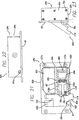
- FIG. 17 is similar to Fig. 2 such that it shows a door or panel 40 retained relative to a frame 38.
- a retaining structure such as a hinge 50 is also provided.
- the latch mechanism 24a is similar to that as shown in Figs. 4-16 such that the latch mechanism 24a includes a housing 62a, a bolt 60a and pressure responsive device 66a.
- the latch mechanism 24a as shown in Figs. 17-19 is attached to the wall or frame 38.
- the latch mechanism 24, 24a, 24c is attached to the frame 38 using fasteners extending through mounting holes 121, 121c.
- the fasteners and mounting holes 121 on the housing 62 is just one example of means for attaching the latch to the barrier 16.
- a general diagrammatic cross-sectional view is illustrated as taken along 18-18 in Fig. 17 .
- the bolt 60a is generally diagrammatically shown engaging the panel 40.
- the latch mechanism 24a includes the housing 62a which includes the air cylinder 66a.
- the air cylinder may take other forms but generally the cylinder is a form of pressure responsive device 66, 66a carried on the latch body or housing 62a.
- the pressure responsive device 66a includes a reservoir portion or chamber 93a and an ambient chamber portion 102a.
- the ambient portion or chamber 102a communicates through an opening 134a, or plurality of openings such as with the filter 100, with the ambient atmosphere on the side of the barrier 16 to which the latch 24 is attached.
- the reservoir chamber 93a communicates with the pressure responsive device 66a through an opening 138a or plurality of openings.
- a diaphragm or piston 140 or other movable structure is operatively retained in the pressure responsive device attached through a linkage 76a, such as the pin 76 shown in Fig. 6 , to engage the bolt 60a.
- the linkage 76a may engage the bolt or may actually be linked to the bolt to withdraw the bolt 60a relative to the frame 38.
- the linkage 76a broadly, generally engages or acts upon the bolt 60a to retain the bolt in a retained position to hold the panel closed.
- the linkage 76a withdrawn or otherwise operates on the bolt 60a to disengage or otherwise release the bolt 60a.
- FIG. 19 another embodiment of the pressure responsive device 66b is shown in general diagrammatic form. In this embodiment, many of the same structures are similar to those as shown in Fig. 18 . However, a separate, external reservoir chamber 93b is provided to provide a volume of atmosphere at a second pressure P2. The chamber 93b communicates with the pressure responsive device through orifice 134b. In this embodiment, the reservoir chamber 93b is coupled to the orifice 134b by means of a hose or line 141.
- This embodiment allows a latch 24b, which might otherwise vent on both sides of the barrier 16, to be vented on a single side of the barrier.
- latches have been developed which vent to the passenger compartment as well as the cockpit. This requires openings to the related chambers to be positioned on either side of the barrier 16.
- the separate reservoir 93b of the embodiment as shown in Fig. 19 can be connected to the orifice 134b which might normally be vented to the passenger compartment.
- This embodiment allows retrofitting of existing latches which vent on both sides of the barrier as well as allows more options in providing and producing latch mechanisms.
- the latch mechanism 20c includes a housing 62c, a pressure responsive device 66c and bolt 60c.
- the air cylinder 65c is retained in chamber 102c defined by the housing 62c.
- a reservoir chamber 93c communicates with the ambient chamber 102c by means of the passage 138c.
- orifices 134c are provided on the housing 62c and communicate with the ambient chamber 102c.
- the ambient chamber 102c communicates with the filter or porous side 88c of the air cylinder 65c.
- the reservoir chamber 93c communicates through passage 138c with the air chamber 65c generally on an opposite side of a diaphragm or piston 140c.
- Cover 64c is held in place over open ends of the chambers 102c, 93c by means of screws 72c and a seal 150.
- the bolt 60c is retained in bolt channel 120c.
- a flange 152 is positioned in the channel 120c to which an arm 154 of the bolt 60c is attached by means of a bushing 70c.
- the bushing 70c extends through a bore 155 in the bolt 60c, the bore 156 formed in the flange 152, and a corresponding portion of the bore formed in a side wall 160 of the channel 120c.
- a rivet 157 extends through the bushing 70c to moveable retain in the bolt 60c in the channel 120c.
- An opposing side wall 162 and base 164 define the channel 120c.
- the bolt 60c is pivotable into and out of the channel 120c about the bushing 70c.
- a bore or receptacle 118c is formed in a portion of the bolt 60c for receiving components of the retainer assembly 80c. Similar to the retainer assembly 80 described above, the retainer assembly 80c includes a roller 85c which is captively retained in the receptacle 118c, a plug 89c, spring 87c and adjustment screw 91c which is threadably engaged with corresponding portion of the receptacle 118c. Instead of acting directly on a component of the bolt 60c such as shown in Fig. 6 , the retainer assembly 80c provides a biasing force against a detent anchor 168 mounted to the base 164 by screws 170.
- the air cylinder 65c includes a pin 76c which is operatively retained in the air cylinder 66c, connected to the piston 140, and extends outwardly into a corresponding aperture 78c on the bolt 60c.
- the aperture 78c need not extend all the way through the corresponding portion of the bolt 60c but may be provided in the form of a recess for receiving the pin 76c.
- the bolt 60c In the locked position, the bolt 60c is generally flush with a top 61 of the housing 62c. An extending finger 174 of the bolt 60c extends outwardly away from the edge of the housing to engage a corresponding panel or other structure.
- a change in pressure on the side (61) of the latch mechanism 24c facing the relevant compartment will cause a change in pressure in the ambient chamber 102c communicating through apertures 134c. This change in pressure will affect the air cylinder 65c, retained in place in the chamber 102c by screw 176, by causing the pin 76c to be withdrawn into the air chamber 65c.
- the pin 76c will shift only if the pressure differential in the ambient chamber 102c is sufficiently greater than the pressure in the reservoir chamber 93c and sufficient to overcome the biasing force of spring 105c. Assuming that there is a significant pressure differential, the pin 76c will be disengaged from the aperture 78c. Disengagement of the pin 76c from the aperture 78c allows rotating or rotation of the finger 174 of the bolt 60c away from the corresponding surface. Generally, the bolt 60c will not move unless the force acting on the panel 40 to which it is related is sufficient to overcome the detent force provided by the retaining mechanism 80c.
- the transferred from the panel through on the finger 174 will cause the roller 85c to be moved relative to the anchor 168 causing a compression in the spring 87c.
- the roller 85c will disengage the anchor 168 thereby allowing free movement of the bolt 60c and disengagement of the panel to which the latch mechanism is attached.
- the latch mechanism as disclosed provides a method of latching or holding a panel or door in a closed position against forces applied thereto.
- the latch mechanism includes structures which function to retain the panel in the closed or latched position subject to disengagement in response to a pressure differential.
- the pressure differential is sensed only on one side of a barrier to which the latch is attached. During a decompression event, the pressure on the other side of the barrier generally has little or no effect on the operation of the latch mechanism.
- Sensing of the pressure differential on a single side of the barrier is accomplished by including the air cylinder 66b or other pressure sensing device, including electrical, mechanical, hydraulic, pneumatic and any other suitable pressure sensing device.
- the present disclosure includes a reservoir which maintains a generally constant pressure relative to ambient. This reservoir or reservoir chamber does not change in response to a rapid change in ambient pressure.
- the latch mechanism is provided including a bolt retained in a housing thereof.
- the air cylinder communicates with a reservoir chamber and is operatively coupled to the bolt.
- the bolt is retained in a locked position when the ambient pressure, P1, is generally equal to the reservoir pressure P2.
- P1 the ambient pressure
- P2 the ambient pressure
- a retaining mechanism can be provided to prevent disengagement of the bolt resulting from unintended or anomalous pressure changes.
Landscapes
- Engineering & Computer Science (AREA)
- Aviation & Aerospace Engineering (AREA)
- Mechanical Engineering (AREA)
- Pressure Vessels And Lids Thereof (AREA)
- Measuring Fluid Pressure (AREA)
- Actuator (AREA)
- Compressors, Vaccum Pumps And Other Relevant Systems (AREA)
Claims (20)
- Mécanisme de verrouillage (24) destiné à retenir de manière amovible une première structure (40) par rapport à une seconde structure (38), le mécanisme de verrouillage comprenant :un boîtier (62) pouvant être fixé sur au moins soit la première structure (38) et la seconde structure (40) ;un boulon (60) placé sur le boîtier de manière amovible ;une partie du pêne venant en butée contre une partie de l'autre d'une première structure et d'une seconde structure afin d'empêcher le déplacement d'une première structure par rapport à une seconde structure ;un dispositif réactif à la pression (66) destiné à détecter une diminution de pression sur un côté d'un panneau (40) ;un dispositif d'engagement de boulon (76) relié au dispositif réactif à la pression et pouvant se déplacer de manière mobile en réponse au fonctionnement du dispositif réactif à la pression ; etune structure de réception (78) sur le boulon, destinée à engager au moins une partie du dispositif d'engagement de boulon afin d'empêcher le déplacement du boulon avant le fonctionnement du dispositif réactif à la pression.
- Mécanisme de verrouillage selon la revendication 1, dans lequel le boulon (60) est retenu de façon pivotante sur le boîtier.
- Mécanisme de verrouillage selon la revendication 1, dans lequel le dispositif réactif à la pression (66) est placé sur le boîtier.
- Mécanisme de verrouillage selon la revendication 1, le dispositif réactif à la pression (66) comprenant en outre un cylindre à air (65) et un réservoir (93), le cylindre à air ayant un premier côté (88) communiquant avec l'atmosphère ambiante sur le côté d'un panneau (40) sur lequel le mécanisme de verrouillage est fixé, et un second côté communiquant avec le réservoir (93), le premier côté (88) étant exposé à des changements rapides de pression dans l'atmosphère ambiante, et le second côté étant généralement isolé des changements rapides de pression dans l'atmosphère ambiante.
- Mécanisme de verrouillage selon la revendication 1, dans lequel le dispositif réactif à la pression (66a) comprend un diaphragme réactif à la pression (140) retenu dans une chambre réactive à la pression (102a), la chambre comprenant une première ouverture (134a) communiquant avec un premier volume et une seconde ouverture (138a) communiquant avec un second volume, une différence de pression entre le premier volume et le second volume agissant sur le diaphragme réactif à la pression (140) dans la chambre.
- Mécanisme de verrouillage selon la revendication 5, dans lequel, en outre, la pression du premier volume est définie par l'atmosphère ambiante et la pression du second volume est définie par un réservoir (93a) communiquant avec la chambre réactive à la pression (102a) dans laquelle le réservoir est généralement isolé de l'atmosphère ambiante.
- Mécanisme de verrouillage selon la revendication 1, dans lequel le dispositif réactif à la pression (66) comprend un piston pneumatique (140c), retenu dans une chambre réactive à la pression, la chambre réactive à la pression comprenant une première ouverture communiquant avec un premier volume (102c) ayant une première pression et une seconde ouverture (138c) communiquant avec un second volume (93c) ayant une seconde pression, une différence de pression entre le premier volume et le second volume commandant le piston dans la chambre.
- Mécanisme de verrouillage selon la revendication 1, dans lequel le dispositif réactif à la pression (66) comprend un dispositif électrique de détection de pression et un dispositif mobile relié au dispositif électrique de détection de pression, le dispositif électrique de détection de pression communiquant avec un premier volume ayant une première pression et un second volume ayant une seconde pression.
- Mécanisme de verrouillage selon la revendication 1, comprenant en outre un mécanisme de retenue (80) fournissant une force de retenue afin de retenir le boulon (60) dans une position verrouillée avant de dépasser une force de retenue prédéterminée.
- Mécanisme de verrouillage (24) destiné à retenir de façon amovible un panneau (40) par rapport à un cadre (38), le mécanisme de verrouillage comprenant :un boîtier de verrou (62) pouvant être fixé sur au moins un panneau ou une structure ;un boulon (60) porté de manière pivotante sur le boîtier de verrou ;une partie de boulon s'étendant depuis le boîtier de verrou afin de venir en butée contre une partie de l'autre d'un panneau et d'un cadre afin d'empêcher le déplacement d'un panneau par rapport à une structure ;un élément coulissant (74) porté de façon déplaçable sur la boîtier de verrou et relié au boulon ;un dispositif réactif à la pression (66) réagissant à au moins une diminution de pression sur le côté d'un panneau sur lequel le dispositif de verrouillage est fixé ;une goupille d'engagement de boulon (76) reliée au dispositif réactif à la pression, la goupille d'engagement de boulon pouvant se déplacer de manière mobile en réponse au fonctionnement du dispositif réactif à la pression ; etun moyen (80) destiné à retenir l'élément coulissant afin d'engager au moins une partie de la goupille d'engagement de boulon de façon à empêcher l'élément coulissant de coulisser avant le fonctionnement du dispositif réactif à la pression.
- Mécanisme de verrouillage selon la revendication 10, dans lequel le dispositif réactif à la pression (66) comprend un moyen destiné à détecter au moins une première pression et un réservoir de pression (93) définissant une seconde pression, généralement isolée de la première pression, le dispositif réactif à la pression fonctionnant en réponse à une différence entre une première pression et une seconde pression.
- Mécanisme de verrouillage selon la revendication 10, dans lequel le dispositif réactif à la pression est installé sur le boîtier du verrou (62).
- Mécanisme de verrouillage selon la revendication 10, dans lequel au moins une partie du dispositif réactif à la pression (66) est séparée du boîtier et communique avec le boîtier.
- Mécanisme de verrouillage selon la revendication 10, le dispositif réactif à la pression comprenant en outre un cylindre à air (65) et un réservoir (93), le cylindre à air ayant un premier côté (88) communiquant avec l'atmosphère ambiante sur le côté d'un panneau (40) sur lequel le mécanisme de verrouillage est fixé, et un second côté communiquant avec le réservoir (93), le premier côté (88) étant exposé à des changements rapides de pression dans l'atmosphère ambiante et le second côté étant généralement isolé des changements rapides de pression dans l'atmosphère ambiante.
- Mécanisme de verrouillage selon la revendication 10, dans lequel le dispositif réactif à la pression (66) comprend un piston pneumatique (140c), retenu dans une chambre de piston, la chambre de piston comprenant une première ouverture communiquant avec un premier volume ayant une première pression, et une seconde ouverture communiquant avec un second volume ayant une seconde pression, une différence de pression entre le premier volume et le second volume commandant le piston dans la chambre.
- Mécanisme de verrouillage selon la revendication 10, dans lequel le dispositif réactif à la pression (66) comprend un diaphragme réactif à la pression (140) retenu dans une chambre réactive à la pression, la chambre comprenant une première ouverture communiquant avec un premier volume et une seconde ouverture communiquant avec un second volume, une différence de pression entre le premier volume et le second volume agissant sur le diaphragme réactif à la pression dans la chambre.
- Mécanisme de verrouillage selon la revendication 10, dans lequel le dispositif réactif à la pression (66) comprend un dispositif électrique de détection de pression et un dispositif mobile relié au dispositif électrique de détection de pression, le dispositif électrique de détection de pression communiquant avec un premier volume ayant une première pression et un second volume ayant une seconde pression.
- Mécanisme de verrouillage selon la revendication 10, comprenant en outre un mécanisme de retenue (80) fournissant une force de retenue sur le boulon.
- Procédé de verrouillage commandé d'un panneau (40) par rapport à un cadre (38), le procédé de verrouillage réagissant à une différence de pression détectée sur un côté d'un panneau sur lequel le mécanisme de verrouillage est fixé, le procédé comprenant les étapes qui consistent à :prévoir un mécanisme de verrouillage (24) associé au panneau ;prévoir un boulon (60) fixé de manière amovible sur le mécanisme de verrouillage, le boulon étant associé au panneau ;prévoir un dispositif réactif à la pression (66) relié au boulon, le dispositif réactif à la pression communiquant avec l'atmosphère ambiante ;prévoir un réservoir (93) communiquant avec le dispositif réactif à la pression, le réservoir étant généralement isolé de l'atmosphère ambiante ;maintenir le retenir le boulon (60) en contact avec un panneau ;détecter la pression sur un côté d'un panneau ;commander le dispositif réactif à la pression (66) en réponse à la différence de pression entre le réservoir et l'atmosphère ambiante ;désengager le boulon (60) d'un panneau lors du développement d'une différence de pression selon un degré prédéterminé ; etdéplacer un panneau par rapport à un cadre lors du désengagement du boulon sur un panneau.
- Mécanisme de verrouillage (24) destiné à retenir de manière amovible un panneau (40), le mécanisme de verrouillage comprenant :un dispositif réactif à la pression (66) fixé sur un boîtier (62) et communiquant avec l'atmosphère ambiante ;un réservoir (93) généralement isolé de l'atmosphère ambiante et communiquant avec le dispositif réactif à la pression ;un boulon (60) fixé de manière amovible sur le boîtier et engagé avec le dispositif réactif à la pression ; etle dispositif réactif à la pression (66) libérant le boulon après lors de la détection d'une différence de pression entre l'atmosphère ambiante et le réservoir.
Applications Claiming Priority (3)
| Application Number | Priority Date | Filing Date | Title |
|---|---|---|---|
| US38908102P | 2002-06-14 | 2002-06-14 | |
| US389081P | 2002-06-14 | ||
| PCT/US2003/018908 WO2003106796A2 (fr) | 2002-06-14 | 2003-06-16 | Verrou a reservoir reagissant a un changement de pression |
Publications (3)
| Publication Number | Publication Date |
|---|---|
| EP1576248A2 EP1576248A2 (fr) | 2005-09-21 |
| EP1576248A4 EP1576248A4 (fr) | 2009-06-03 |
| EP1576248B1 true EP1576248B1 (fr) | 2017-03-01 |
Family
ID=29736585
Family Applications (1)
| Application Number | Title | Priority Date | Filing Date |
|---|---|---|---|
| EP03751775.2A Expired - Lifetime EP1576248B1 (fr) | 2002-06-14 | 2003-06-16 | Verrou a reservoir reagissant a un changement de pression |
Country Status (5)
| Country | Link |
|---|---|
| EP (1) | EP1576248B1 (fr) |
| AU (1) | AU2003269888A1 (fr) |
| CA (1) | CA2489598C (fr) |
| ES (1) | ES2625802T3 (fr) |
| WO (1) | WO2003106796A2 (fr) |
Families Citing this family (13)
| Publication number | Priority date | Publication date | Assignee | Title |
|---|---|---|---|---|
| FR2873980B1 (fr) * | 2004-08-03 | 2006-10-13 | Airbus Sas | Porte renforcee |
| CA2576303C (fr) | 2004-08-03 | 2013-01-15 | Airbus | Porte renforcee |
| FR2873979B1 (fr) * | 2004-08-03 | 2008-01-11 | Airbus Sas | Porte interieure de securite pour un aeronef |
| EP1773666B1 (fr) | 2004-08-03 | 2013-11-06 | Airbus | Porte interieure de securite pour un aeronef |
| US7032863B1 (en) * | 2004-10-15 | 2006-04-25 | The Boeing Company | Increased security flight deck door strike apparatus and method |
| EP2663707B1 (fr) * | 2011-01-10 | 2019-05-15 | Hartwell Corporation | Mécanisme de verrouillage à détente de pression |
| NL2020765B1 (en) * | 2018-04-13 | 2019-10-23 | Boeing Co | Aircraft privacy door and door frame assembly |
| EP3524509B1 (fr) * | 2018-02-08 | 2020-10-07 | The Boeing Company | Porte intimité d'aéronef et ensemble de cadre de porte |
| EP3524512B1 (fr) * | 2018-02-08 | 2021-04-21 | The Boeing Company | Porte intimité d'aéronef et ensemble de cadre de porte |
| US11305860B2 (en) | 2018-02-08 | 2022-04-19 | The Boeing Company | Aircraft privacy door and door frame assembly |
| US10766597B2 (en) | 2018-02-08 | 2020-09-08 | The Boeing Company | Aircraft privacy door and door frame assembly |
| US11299250B2 (en) | 2018-02-08 | 2022-04-12 | The Boeing Company | Aircraft privacy door and door frame assembly |
| CN114394330B (zh) * | 2021-12-21 | 2024-04-05 | 重庆特斯联智慧科技股份有限公司 | 物流机器人的货仓锁闭结构 |
Family Cites Families (4)
| Publication number | Priority date | Publication date | Assignee | Title |
|---|---|---|---|---|
| US6755448B2 (en) * | 2001-06-20 | 2004-06-29 | Hartwell Corporation | Blowout latch |
| US20030052227A1 (en) * | 2001-09-17 | 2003-03-20 | Pittman Donald Merve | Protective shield for aircraft cockpit crew |
| US6866226B2 (en) * | 2001-10-04 | 2005-03-15 | Hartwell Corporation | Pressure responsive blowout latch |
| WO2003029585A2 (fr) * | 2001-10-04 | 2003-04-10 | Hartwell Corporation | Pene dormant sensible a la pression |
-
2003
- 2003-06-16 ES ES03751775.2T patent/ES2625802T3/es not_active Expired - Lifetime
- 2003-06-16 WO PCT/US2003/018908 patent/WO2003106796A2/fr not_active Application Discontinuation
- 2003-06-16 EP EP03751775.2A patent/EP1576248B1/fr not_active Expired - Lifetime
- 2003-06-16 CA CA2489598A patent/CA2489598C/fr not_active Expired - Lifetime
- 2003-06-16 AU AU2003269888A patent/AU2003269888A1/en not_active Abandoned
Non-Patent Citations (1)
| Title |
|---|
| None * |
Also Published As
| Publication number | Publication date |
|---|---|
| EP1576248A2 (fr) | 2005-09-21 |
| WO2003106796A3 (fr) | 2005-12-29 |
| EP1576248A4 (fr) | 2009-06-03 |
| WO2003106796A2 (fr) | 2003-12-24 |
| ES2625802T3 (es) | 2017-07-20 |
| AU2003269888A1 (en) | 2003-12-31 |
| CA2489598A1 (fr) | 2003-12-24 |
| CA2489598C (fr) | 2011-08-23 |
Similar Documents
| Publication | Publication Date | Title |
|---|---|---|
| US6866227B2 (en) | Pressure responsive blowout latch with reservoir | |
| EP1446543B1 (fr) | Dispositif de verrouillage a deplacement reagissant a la pression | |
| EP1438473B1 (fr) | Pene dormant sensible a la pression | |
| EP1576248B1 (fr) | Verrou a reservoir reagissant a un changement de pression | |
| US4681286A (en) | Door anti-hijacking latch/lock mechanism with pneumatic decompression override | |
| US4522359A (en) | Door anti-hijacking latch/lock mechanism with pneumatic decompression override | |
| US8267464B2 (en) | Latching system | |
| US7568659B2 (en) | Door which is intended to be positioned between the cockpit and the cabin of an aircraft | |
| EP3683138B1 (fr) | Système de verrouillage de porte doté d'un mécanisme de libération rapide | |
| EP1398437B1 (fr) | Mécanisme de verrouillage | |
| JP3947511B2 (ja) | 航空機の操縦室ドア | |
| EP1427904B1 (fr) | Appareil d'acces pour cockpit d'aeronef | |
| EP0121517B1 (fr) | Mecanisme de verrouillage de porte anti-detournement avec commande de derogation de decompression pneumatique | |
| US8602464B2 (en) | Decompression vent latching mechanism | |
| US20030192989A1 (en) | Security bulkhead and door construction | |
| EP3524509B1 (fr) | Porte intimité d'aéronef et ensemble de cadre de porte | |
| EP3524511B1 (fr) | Porte de confidentialité d'aéronef et ensemble cadre de porte | |
| ES2864220T3 (es) | Puerta de privacidad de aeronave y conjunto de marco de puerta |
Legal Events
| Date | Code | Title | Description |
|---|---|---|---|
| PUAI | Public reference made under article 153(3) epc to a published international application that has entered the european phase |
Free format text: ORIGINAL CODE: 0009012 |
|
| 17P | Request for examination filed |
Effective date: 20050105 |
|
| AK | Designated contracting states |
Kind code of ref document: A2 Designated state(s): AT BE BG CH CY CZ DE DK EE ES FI FR GB GR HU IE IT LI LU MC NL PT RO SE SI SK TR |
|
| AX | Request for extension of the european patent |
Extension state: AL LT LV MK |
|
| DAX | Request for extension of the european patent (deleted) | ||
| PUAK | Availability of information related to the publication of the international search report |
Free format text: ORIGINAL CODE: 0009015 |
|
| RIC1 | Information provided on ipc code assigned before grant |
Ipc: B64D 11/00 20060101AFI20060109BHEP |
|
| A4 | Supplementary search report drawn up and despatched |
Effective date: 20090507 |
|
| 17Q | First examination report despatched |
Effective date: 20120404 |
|
| GRAP | Despatch of communication of intention to grant a patent |
Free format text: ORIGINAL CODE: EPIDOSNIGR1 |
|
| INTG | Intention to grant announced |
Effective date: 20160915 |
|
| GRAS | Grant fee paid |
Free format text: ORIGINAL CODE: EPIDOSNIGR3 |
|
| GRAA | (expected) grant |
Free format text: ORIGINAL CODE: 0009210 |
|
| AK | Designated contracting states |
Kind code of ref document: B1 Designated state(s): AT BE BG CH CY CZ DE DK EE ES FI FR GB GR HU IE IT LI LU MC NL PT RO SE SI SK TR |
|
| REG | Reference to a national code |
Ref country code: GB Ref legal event code: FG4D |
|
| REG | Reference to a national code |
Ref country code: CH Ref legal event code: EP Ref country code: AT Ref legal event code: REF Ref document number: 870950 Country of ref document: AT Kind code of ref document: T Effective date: 20170315 |
|
| REG | Reference to a national code |
Ref country code: IE Ref legal event code: FG4D |
|
| REG | Reference to a national code |
Ref country code: DE Ref legal event code: R096 Ref document number: 60349942 Country of ref document: DE |
|
| REG | Reference to a national code |
Ref country code: FR Ref legal event code: PLFP Year of fee payment: 15 |
|
| REG | Reference to a national code |
Ref country code: NL Ref legal event code: MP Effective date: 20170301 |
|
| REG | Reference to a national code |
Ref country code: AT Ref legal event code: MK05 Ref document number: 870950 Country of ref document: AT Kind code of ref document: T Effective date: 20170301 |
|
| REG | Reference to a national code |
Ref country code: ES Ref legal event code: FG2A Ref document number: 2625802 Country of ref document: ES Kind code of ref document: T3 Effective date: 20170720 |
|
| PG25 | Lapsed in a contracting state [announced via postgrant information from national office to epo] |
Ref country code: FI Free format text: LAPSE BECAUSE OF FAILURE TO SUBMIT A TRANSLATION OF THE DESCRIPTION OR TO PAY THE FEE WITHIN THE PRESCRIBED TIME-LIMIT Effective date: 20170301 Ref country code: GR Free format text: LAPSE BECAUSE OF FAILURE TO SUBMIT A TRANSLATION OF THE DESCRIPTION OR TO PAY THE FEE WITHIN THE PRESCRIBED TIME-LIMIT Effective date: 20170602 |
|
| PG25 | Lapsed in a contracting state [announced via postgrant information from national office to epo] |
Ref country code: SE Free format text: LAPSE BECAUSE OF FAILURE TO SUBMIT A TRANSLATION OF THE DESCRIPTION OR TO PAY THE FEE WITHIN THE PRESCRIBED TIME-LIMIT Effective date: 20170301 Ref country code: BG Free format text: LAPSE BECAUSE OF FAILURE TO SUBMIT A TRANSLATION OF THE DESCRIPTION OR TO PAY THE FEE WITHIN THE PRESCRIBED TIME-LIMIT Effective date: 20170601 Ref country code: AT Free format text: LAPSE BECAUSE OF FAILURE TO SUBMIT A TRANSLATION OF THE DESCRIPTION OR TO PAY THE FEE WITHIN THE PRESCRIBED TIME-LIMIT Effective date: 20170301 |
|
| PG25 | Lapsed in a contracting state [announced via postgrant information from national office to epo] |
Ref country code: NL Free format text: LAPSE BECAUSE OF FAILURE TO SUBMIT A TRANSLATION OF THE DESCRIPTION OR TO PAY THE FEE WITHIN THE PRESCRIBED TIME-LIMIT Effective date: 20170301 |
|
| PG25 | Lapsed in a contracting state [announced via postgrant information from national office to epo] |
Ref country code: SK Free format text: LAPSE BECAUSE OF FAILURE TO SUBMIT A TRANSLATION OF THE DESCRIPTION OR TO PAY THE FEE WITHIN THE PRESCRIBED TIME-LIMIT Effective date: 20170301 Ref country code: EE Free format text: LAPSE BECAUSE OF FAILURE TO SUBMIT A TRANSLATION OF THE DESCRIPTION OR TO PAY THE FEE WITHIN THE PRESCRIBED TIME-LIMIT Effective date: 20170301 Ref country code: CZ Free format text: LAPSE BECAUSE OF FAILURE TO SUBMIT A TRANSLATION OF THE DESCRIPTION OR TO PAY THE FEE WITHIN THE PRESCRIBED TIME-LIMIT Effective date: 20170301 Ref country code: RO Free format text: LAPSE BECAUSE OF FAILURE TO SUBMIT A TRANSLATION OF THE DESCRIPTION OR TO PAY THE FEE WITHIN THE PRESCRIBED TIME-LIMIT Effective date: 20170301 |
|
| PG25 | Lapsed in a contracting state [announced via postgrant information from national office to epo] |
Ref country code: PT Free format text: LAPSE BECAUSE OF FAILURE TO SUBMIT A TRANSLATION OF THE DESCRIPTION OR TO PAY THE FEE WITHIN THE PRESCRIBED TIME-LIMIT Effective date: 20170703 |
|
| REG | Reference to a national code |
Ref country code: DE Ref legal event code: R097 Ref document number: 60349942 Country of ref document: DE |
|
| PLBE | No opposition filed within time limit |
Free format text: ORIGINAL CODE: 0009261 |
|
| STAA | Information on the status of an ep patent application or granted ep patent |
Free format text: STATUS: NO OPPOSITION FILED WITHIN TIME LIMIT |
|
| PG25 | Lapsed in a contracting state [announced via postgrant information from national office to epo] |
Ref country code: MC Free format text: LAPSE BECAUSE OF FAILURE TO SUBMIT A TRANSLATION OF THE DESCRIPTION OR TO PAY THE FEE WITHIN THE PRESCRIBED TIME-LIMIT Effective date: 20170301 Ref country code: DK Free format text: LAPSE BECAUSE OF FAILURE TO SUBMIT A TRANSLATION OF THE DESCRIPTION OR TO PAY THE FEE WITHIN THE PRESCRIBED TIME-LIMIT Effective date: 20170301 |
|
| REG | Reference to a national code |
Ref country code: CH Ref legal event code: PL |
|
| 26N | No opposition filed |
Effective date: 20171204 |
|
| PG25 | Lapsed in a contracting state [announced via postgrant information from national office to epo] |
Ref country code: SI Free format text: LAPSE BECAUSE OF FAILURE TO SUBMIT A TRANSLATION OF THE DESCRIPTION OR TO PAY THE FEE WITHIN THE PRESCRIBED TIME-LIMIT Effective date: 20170301 |
|
| REG | Reference to a national code |
Ref country code: IE Ref legal event code: MM4A |
|
| PG25 | Lapsed in a contracting state [announced via postgrant information from national office to epo] |
Ref country code: LU Free format text: LAPSE BECAUSE OF NON-PAYMENT OF DUE FEES Effective date: 20170616 Ref country code: LI Free format text: LAPSE BECAUSE OF NON-PAYMENT OF DUE FEES Effective date: 20170630 Ref country code: CH Free format text: LAPSE BECAUSE OF NON-PAYMENT OF DUE FEES Effective date: 20170630 Ref country code: IE Free format text: LAPSE BECAUSE OF NON-PAYMENT OF DUE FEES Effective date: 20170616 |
|
| REG | Reference to a national code |
Ref country code: BE Ref legal event code: MM Effective date: 20170630 |
|
| REG | Reference to a national code |
Ref country code: FR Ref legal event code: PLFP Year of fee payment: 16 |
|
| PG25 | Lapsed in a contracting state [announced via postgrant information from national office to epo] |
Ref country code: BE Free format text: LAPSE BECAUSE OF NON-PAYMENT OF DUE FEES Effective date: 20170630 |
|
| PG25 | Lapsed in a contracting state [announced via postgrant information from national office to epo] |
Ref country code: HU Free format text: LAPSE BECAUSE OF FAILURE TO SUBMIT A TRANSLATION OF THE DESCRIPTION OR TO PAY THE FEE WITHIN THE PRESCRIBED TIME-LIMIT; INVALID AB INITIO Effective date: 20030616 |
|
| PG25 | Lapsed in a contracting state [announced via postgrant information from national office to epo] |
Ref country code: CY Free format text: LAPSE BECAUSE OF NON-PAYMENT OF DUE FEES Effective date: 20170301 |
|
| PG25 | Lapsed in a contracting state [announced via postgrant information from national office to epo] |
Ref country code: TR Free format text: LAPSE BECAUSE OF FAILURE TO SUBMIT A TRANSLATION OF THE DESCRIPTION OR TO PAY THE FEE WITHIN THE PRESCRIBED TIME-LIMIT Effective date: 20170301 |
|
| PGFP | Annual fee paid to national office [announced via postgrant information from national office to epo] |
Ref country code: IT Payment date: 20220621 Year of fee payment: 20 Ref country code: GB Payment date: 20220628 Year of fee payment: 20 |
|
| PGFP | Annual fee paid to national office [announced via postgrant information from national office to epo] |
Ref country code: FR Payment date: 20220627 Year of fee payment: 20 |
|
| PGFP | Annual fee paid to national office [announced via postgrant information from national office to epo] |
Ref country code: ES Payment date: 20220701 Year of fee payment: 20 Ref country code: DE Payment date: 20220629 Year of fee payment: 20 |
|
| REG | Reference to a national code |
Ref country code: DE Ref legal event code: R071 Ref document number: 60349942 Country of ref document: DE |
|
| REG | Reference to a national code |
Ref country code: ES Ref legal event code: FD2A Effective date: 20230626 |
|
| REG | Reference to a national code |
Ref country code: GB Ref legal event code: PE20 Expiry date: 20230615 |
|
| PG25 | Lapsed in a contracting state [announced via postgrant information from national office to epo] |
Ref country code: ES Free format text: LAPSE BECAUSE OF EXPIRATION OF PROTECTION Effective date: 20230617 |
|
| PG25 | Lapsed in a contracting state [announced via postgrant information from national office to epo] |
Ref country code: GB Free format text: LAPSE BECAUSE OF EXPIRATION OF PROTECTION Effective date: 20230615 |