EP1575341B1 - Dimmer - Google Patents
Dimmer Download PDFInfo
- Publication number
- EP1575341B1 EP1575341B1 EP05003826A EP05003826A EP1575341B1 EP 1575341 B1 EP1575341 B1 EP 1575341B1 EP 05003826 A EP05003826 A EP 05003826A EP 05003826 A EP05003826 A EP 05003826A EP 1575341 B1 EP1575341 B1 EP 1575341B1
- Authority
- EP
- European Patent Office
- Prior art keywords
- control lever
- dimmer
- brightness
- controller
- control
- Prior art date
- Legal status (The legal status is an assumption and is not a legal conclusion. Google has not performed a legal analysis and makes no representation as to the accuracy of the status listed.)
- Active
Links
Images
Classifications
-
- H—ELECTRICITY
- H05—ELECTRIC TECHNIQUES NOT OTHERWISE PROVIDED FOR
- H05B—ELECTRIC HEATING; ELECTRIC LIGHT SOURCES NOT OTHERWISE PROVIDED FOR; CIRCUIT ARRANGEMENTS FOR ELECTRIC LIGHT SOURCES, IN GENERAL
- H05B45/00—Circuit arrangements for operating light-emitting diodes [LED]
- H05B45/20—Controlling the colour of the light
-
- H—ELECTRICITY
- H05—ELECTRIC TECHNIQUES NOT OTHERWISE PROVIDED FOR
- H05B—ELECTRIC HEATING; ELECTRIC LIGHT SOURCES NOT OTHERWISE PROVIDED FOR; CIRCUIT ARRANGEMENTS FOR ELECTRIC LIGHT SOURCES, IN GENERAL
- H05B47/00—Circuit arrangements for operating light sources in general, i.e. where the type of light source is not relevant
- H05B47/10—Controlling the light source
-
- H—ELECTRICITY
- H01—ELECTRIC ELEMENTS
- H01H—ELECTRIC SWITCHES; RELAYS; SELECTORS; EMERGENCY PROTECTIVE DEVICES
- H01H25/00—Switches with compound movement of handle or other operating part
Definitions
- the invention relates to a dimmer with a control lever for adjusting the brightness and color of a light bulb.
- the invention can be used for example for driving LED-based light sources.
- a lighting device which has an intensity control for varying the luminous intensity and color of the light source (light-emitting diode or light-emitting transistor).
- an input device for example, serve a joystick with a joystick, which provides a signal by its relative position to the neutral center position, whereby the color choice is adjusted accordingly in the direction of a particular hue.
- a joystick with potentiometers for color selection and a dial for brightness selection serve.
- a method and a device for the realization of LED lights with color and / or brightness adjustment and the associated control element are known.
- the position of the operator's finger changes the color and the duration of the persistent touch sets the intensity.
- the selected brightness and color is generated via red, green and blue LEDs and possibly additional white LEDs.
- the effective current through the LEDs is set in an energy-saving manner via the ratio of the switch-on time to the switch-off time. It can be used a joystick-like control for the LED light.
- the invention has for its object to provide a dimmer with which not only the brightness of a light source, but also its light color can be adjusted in the desired manner.
- the advantages achieved by the invention are in particular that the light color of a modern light source, z. B. LED-based, depending on the specific use (living room, bedroom, kitchen, conservatory, greenhouse, design light) can be specified in the desired manner.
- the brightness and the desired light color of the light source are set independently of each other and in an easily understandable manner, so that the operation of the dimmer, in spite of increased functionality, is also easily possible for inexperienced persons.
- control lever 4 springs in the unloaded state automatically from the positions A, B, C, D, E, F back to the stable center position.
- the intensity of different color channels red / green / blue
- control lever 4 can be acted upon in its central position with a rotation G "clockwise” and with a rotation H “counterclockwise”.
- a linear movement K towards the appliance insert 3 can be effected.
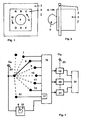
- Fig. 2 in which a side view of the dimmer 1 is shown.
- dimmer device insert 3 with control lever 4 on the front and the cover 2 can be seen.
- Fig. 3 the basic electrical circuit diagram of the dimmer 1 is shown.
- a switching device 5 As essential components are a switching device 5, a controller 16 and z. B. three pulse width modulators as independently adjustable power modules 19, 20, 21 are provided.
- the switching device 5 has a voltage applied via a terminal 22 with a control voltage U H main contact 6, which can selectively and in any order one of the switch contacts 7 - 13 contact.
- the main contact 6 contacts a switching contact 7 - 13
- the contacted switching contact is subjected to the control voltage U H.
- the control lever 4 If the control lever 4 is in its middle position and is neither tilted, turned nor pressed (rest position), the main contact 6 does not contact any of the switch contacts 7 - 13.
- the switch contacts 7 - 13 are connected directly to corresponding control inputs of the controller 16 on the output side.
- the controller 16 has a time detecting element 17, which detects the duration of the presence of a transmitted by the switching contact 13 control signal.
- the time detection member 17 is used to detect / distinguish whether a short-term movement K of the control lever 4, a switching on / off of the dimmer 1 is to be effected or by a prolonged insistence of the control lever 4 in the depressed state , d. H. with regard to the linear movement K, a saving / resetting of the minimum brightness is to be effected.
- the controller 16 controls for each color channel red / green / blue a separate power module 19, 20, 21, for example, pulse width modulator, said pulse width modulators input side to a z. B. with an AC voltage U AC applied terminal 23 are connected and the output side, a light source 24 on LED base supply. Since LED lights do not necessarily work with 230V AC, you can alternatively use z. B. also a small protection voltage of 12V DC are used to power the LED lamp, in such an application corresponding semiconductor actuator / converter for DC or DC voltage as power devices 19, 20, 21 are used.
Abstract
Description
Die Erfindung bezieht sich auf einen Dimmer mit einem Steuerhebel zur Einstellung von Helligkeit und Lichtfarbe eines Leuchtmittels. Die Erfindung kann beispielsweise zur Ansteuerung von Leuchtmitteln auf LED-Basis verwendet werden.The invention relates to a dimmer with a control lever for adjusting the brightness and color of a light bulb. The invention can be used for example for driving LED-based light sources.
Aus der DE 199 42 177 A1 ist eine Beleuchtungsvorrichtung bekannt, welche eine Intensitäts-Steuerung zur Variation der Leuchtintensität und Farbe der Lichtquelle (Leuchtdiode oder Leuchttransistor) aufweist. Als Eingabevorrichtung kann beispielsweise ein Joystick mit einem Bedienknüppel dienen, welcher durch seine relative Position zur neutralen Mittelstellung ein Signal liefert, wodurch die Farbwahl entsprechend in Richtung eines bestimmten Farbtones eingestellt wird. Alternativ kann ein Joystick mit Potentiometern zur Farbwahl und ein Einstellrad zur Helligkeitswahl dienen.From DE 199 42 177 A1 a lighting device is known, which has an intensity control for varying the luminous intensity and color of the light source (light-emitting diode or light-emitting transistor). As an input device, for example, serve a joystick with a joystick, which provides a signal by its relative position to the neutral center position, whereby the color choice is adjusted accordingly in the direction of a particular hue. Alternatively, a joystick with potentiometers for color selection and a dial for brightness selection serve.
Aus der DE 102 39 449 A1 sind ein Verfahren und eine Vorrichtung zur Realisierung von LED-Leuchten mit Farb- und/oder Helligkeitseinstellung und dem dazugehörigen Bedienelement bekannt. Über die Position des Fingers des Bedieners wird die Farbe und über die Dauer der verharrenden Berührung wird die Intensität eingestellt. Die gewählte Helligkeit und Farbe wird über rote, grüne und blaue LEDs und ggf. zusätzliche weiße LEDs erzeugt. Über elektronische Schaltelemente wird energiesparend der effektive Strom durch die LEDs über das Verhältnis von Einschalt- zur Ausschaltzeit vorgegeben. Es kann ein joystickähnliches Bedienelement für die LED-Leuchte eingesetzt werden.From DE 102 39 449 A1 a method and a device for the realization of LED lights with color and / or brightness adjustment and the associated control element are known. The position of the operator's finger changes the color and the duration of the persistent touch sets the intensity. The selected brightness and color is generated via red, green and blue LEDs and possibly additional white LEDs. By means of electronic switching elements, the effective current through the LEDs is set in an energy-saving manner via the ratio of the switch-on time to the switch-off time. It can be used a joystick-like control for the LED light.
Die in der Installationstechnik allgemein bekannten Dimmer erlauben es, Leuchtmittel durch Druck auf ein Bedienelement (mit gekoppeltem Potentiometer) ein- und auszuschalten und durch Drehen am Bedienelement in der Helligkeit zu steuern. Für übliche Lichtquellen (Glühlampen, Halogenglühlampen) reicht diese Funktionalität vollkommen aus. Zwischenzeitlich sind moderne Leuchtmittel, z. B. auf LED-Basis, erhältlich, bei denen das weiße Licht durch Mischung aus den drei Grundfarben rot/grün/blau erzeugt wird. Solche Leuchtmittel können mit herkömmlichen Dimmem ebenfalls in ihrer Helligkeit variiert werden.The well-known in the installation technology dimmers allow light bulbs by pressing an operating element (with a coupled potentiometer) on and off and control by turning the control in the brightness. For conventional light sources (incandescent, halogen bulbs), this functionality is completely sufficient. In the meantime, modern bulbs, z. LED-based, where the white light is generated by mixing the three primary colors red / green / blue. Such bulbs can also be varied in brightness with conventional dimmers.
Der Erfindung liegt die Aufgabe zugrunde, einen Dimmer anzugeben, mit dem nicht nur die Helligkeit eines Leuchtmittels, sondern darüber hinaus auch dessen Lichtfarbe in gewünschter Weise eingestellt werden kann.The invention has for its object to provide a dimmer with which not only the brightness of a light source, but also its light color can be adjusted in the desired manner.
Diese Aufgabe wird erfindungsgemäß gelöst durch einen Dimmer mit einem Bedienelement, welches mindestens einen Leistungsbaustein ansteuert, um derart die gewünschte Helligkeit eines Leuchtmittels einzustellen, wobei
- ein Steuerhebel als Bedienelement vorgesehen ist, welcher in unterschiedliche Positionen gekippt und/oder gedreht und/oder gedrückt werden kann, um derart Schaltkontakte einer Schalteinrichtung zu betätigen, welche einen Kontroller ansteuern, um derart mit Hilfe eines pro Farbkanal separaten Leistungsbausteines außer der gewünschten Helligkeit zusätzlich die gewünschte Lichtfarbe eines Leuchtmittels einzustellen,
- der Steuerhebel bei Drehung einen an den Kontroller angeschlossenen Inkrementalgeber beaufschlagt, um derart die Helligkeit des Leuchtmittels einzustellen,
- der Steuerhebel aus einer als Ruhepositioh dienenden Mittelstellung heraus in sechs unterschiedliche Positionen "oben links", "oben Mitte", oben rechts", "unten links", "unten Mitte", "unten rechts" kippbar ist, wodurch die Intensität von drei verschiedenen Farbkanälen an den Kontroller vorgebbar und durch die Leistungsbausteine einstellbar ist und
- der Kontroller ein Zeiterfassungsglied aufweist, das die Zeitdauer der Beaufschlagung eines Schaltkontaktes infolge eines Drückens des Steuerhebels erfasst, wodurch durch kurzzeitiges Drücken des Steuerhebels ein Einschalten oder Ausschalten des Dimmers erfolgt und ein Abspeichem einer vorgegebenen Mindesthelligkeit erfolgt, sobald der Steuerhebel für eine vorgegebene längere Zeitspanne in seiner Mittelstellung gedrückt gehalten wird.
- a control lever is provided as a control element, which can be tilted in different positions and / or rotated and / or pressed to actuate such switching contacts a switching device, which control a controller, in order to additionally with the aid of a per color channel separate power module in addition to the desired brightness to set the desired light color of a light source,
- upon rotation, the control lever is acted upon by an incremental encoder connected to the controller so as to adjust the brightness of the illuminant,
- the joystick is tiltable from a center position serving as a rest position into six different positions "top left", "top center", top right "," bottom left "," bottom center "," bottom right ", thereby increasing the intensity of three different positions Color channels can be specified to the controller and by the power modules is adjustable and
- the controller has a time detecting member which detects the time duration of the application of a switching contact due to a pressing of the control lever, whereby momentary actuation of the control lever causes the dimmer to be switched on or off and a predetermined minimum brightness to be stored as soon as the control lever is pressed in its middle position for a predetermined, longer period of time.
Die mit der Erfindung erzielbaren Vorteile bestehen insbesondere darin, dass die Lichtfarbe eines modernen Leuchtmittels, z. B. auf LED-Basis, in Abhängigkeit des konkreten Einsatzes (Wohnraum, Schlafraum, Küche, Wintergarten, Gewächshaus, Designleuchte) in gewünschter Weise vorgegeben werden kann. Dabei erfolgen die Einstellung von Helligkeit und gewünschter Lichtfarbe des Leuchtmittels unabhängig voneinander und in einfach verständlicher Art und Weise, so dass die Bedienung des Dimmers trotz erhöhter Funktionalität auch ungeübten Personen leicht möglich ist.The advantages achieved by the invention are in particular that the light color of a modern light source, z. B. LED-based, depending on the specific use (living room, bedroom, kitchen, conservatory, greenhouse, design light) can be specified in the desired manner. The brightness and the desired light color of the light source are set independently of each other and in an easily understandable manner, so that the operation of the dimmer, in spite of increased functionality, is also easily possible for inexperienced persons.
Weitere Vorteile sind aus der nachstehenden Beschreibung ersichtlich.Further advantages will be apparent from the following description.
Vorteilhafte Ausgestaltungen der Erfindung sind in den Unteransprüchen gekennzeichnet.Advantageous embodiments of the invention are characterized in the subclaims.
Die Erfindung wird nachstehend anhand der in der Zeichnung dargestellten Ausführungsbeispiele erläutert. Es zeigen:
- Fig.1
- eine Sicht auf die Frontseite eines Dimmers,
- Fig. 2
- eine Seitenansicht des Dimmers,
- Fig. 3
- das prinzipielle elektrische Schaltschema des Dimmers.
- Fig.1
- a view of the front of a dimmer,
- Fig. 2
- a side view of the dimmer,
- Fig. 3
- the basic electrical circuit diagram of the dimmer.
In Fig. 1 ist eine Sicht auf die Frontseite eines Dimmers dargestellt. Wie bei einem elektrischen Installationsgerät üblich, ist der Dimmer 1 mehrteilig aufgebaut und besteht aus einem Dimmer-Geräteeinsatz 3 (in Unterputz-Ausführung, mit Tragring) und einem Abdeckrahmen 2. Zur Einstellung eines an den Dimmer 1 angeschlossenen Leuchtmittels dient ein an der Frontseite des Geräteeinsatzes 3 angeordneter Steuerhebel 4, auch unter der Bezeichnung "Joystick" geläufig. Dieser Steuerhebel 4 weist eine als "Ruheposition" dienende Mittelstellung auf und kann aus dieser Mittelstellung heraus in sechs unterschiedliche Positionen gekippt werden:
- Position A "oben links"
- Position B "oben Mitte"
- Position C "oben rechts"
- Position D "unten links"
- Position E "unten Mitte"
- Position F "unten rechts"
- Position A "top left"
- Position B "top center"
- Position C "top right"
- Position D "bottom left"
- Position E "bottom center"
- Position F "bottom right"
Dabei federt der Steuerhebel 4 jeweils im unbelasteten Zustand selbsttätig von den Positionen A, B, C, D, E, F zurück in die stabile Mittelstellung. Wie nachfolgend noch näher erläutert, ist hierdurch die Intensität verschiedener Farbkanäle (rot/grün/blau) einstellbar.Here, the control lever 4 springs in the unloaded state automatically from the positions A, B, C, D, E, F back to the stable center position. As explained in more detail below, the intensity of different color channels (red / green / blue) can thereby be set.
Des weiteren kann der Steuerhebel 4 in seiner Mittelstellung mit einer Drehung G "im Uhrzeigersinn" sowie mit einer Drehung H "entgegen dem Uhrzeigersinn" beaufschlagt werden.Furthermore, the
Ferner kann durch Drücken auf den Steuerhebel 4 eine lineare Bewegung K in Richtung zum Geräteeinsatz 3 hin bewirkt werden. Dies ist in Fig. 2 zu erkennen, in welcher eine Seitenansicht des Dimmers 1 dargestellt ist. Es sind der Dimmer-Geräteeinsatz 3 mit Steuerhebel 4 an der Frontseite sowie der Abdeckrahmen 2 zu erkennen.Further, by pressing the
In Fig. 3 ist das prinzipielle elektrische Schaltschema des Dimmers 1 dargestellt. Als wesentliche Baukomponenten sind eine Schalteinrichtung 5, ein Kontroller 16 sowie z. B. drei Pulsweitenmodulatoren als unabhängig voneinander einstellbare Leistungsbausteine 19, 20, 21 vorgesehen. Die Schalteinrichtung 5 weist einen über eine Klemme 22 mit einer Steuerspannung UH beaufschlagten Hauptkontakt 6 auf, welcher wahlweise und in beliebiger Reihenfolge einen der Schaltkontakte 7 - 13 kontaktieren kann. Sobald der Hauptkontakt 6 einen Schaltkontakt 7 - 13 kontaktiert, wird der kontaktierte Schaltkontakt mit der Steuerspannung UH beaufschlagt. Befindet sich der Steuerhebel 4 in seiner Mittelstellung und wird dabei weder gekippt, gedreht noch gedrückt (Ruheposition), kontaktiert der Hauptkontakt 6 keinen der Schaltkontakte 7 - 13. Die Schaltkontakte 7 - 13 sind ausgangsseitig direkt mit entsprechenden Steuereingängen des Kontrollers 16 verbunden. Dabei besitzt der Kontroller 16 ein Zeiterfassungsglied 17, welches die Zeitdauer des Anstehens eines durch den Schaltkontakt 13 übermittelten Steuersignals erfasst.In Fig. 3, the basic electrical circuit diagram of the
Bei Drehung des Steuerhebels 4 wird ein mit dem Steuerhebel 4 direkt gekoppelter und ebenfalls an Klemme 22 angeschlossener Inkrementalgeber 18 beaufschlagt, welcher einen entsprechenden Steuereingang des Kontrollers 16 in Abhängigkeit der Drehbewegung G oder H des Steuerhebels 4 mit Signalen beaufschlagt.Upon rotation of the
Die Bedienung des Dimmers 1 erfolgt in folgender Weise:
- I. Bei Drücken des in seiner Mittelstellung befindlichen Steuerhebels 4 - siehe lineare Bewegung K -
beaufschlagt Schaltkontakt 13 den entsprechenden Steuereingang des Kontrollers 16 und es erfolgt ein Einschalten oder Ausschalten desDimmers 1. Dabei wird das relativ kurzzeitige Drücken des Steuerhebels 4vom Zeiterfassungsglied 17 detektiert. - II. Beim Kippen des
Steuerhebels 4 in die Position A "oben links" beaufschlagt der Schaltkontakt 7 den entsprechenden Steuereingang desKontrollers 16, wodurch vorgegeben wird, dass die Lichtfarbe des Leuchtmittels in Richtung "mehr rot" einzustellen ist. - III. Beim Kippen des
Steuerhebels 4 in die Position B "oben Mitte" beaufschlagt der Schaltkontakt 8 den entsprechenden Steuereingang desKontrollers 16, wodurch vorgegeben wird, dass die Lichtfarbe des Leuchtmittels in Richtung "mehr grün" einzustellen ist. - IV. Beim Kippen des
Steuerhebels 4 in die Position C "oben rechts" beaufschlagt der Schaltkontakt 9 den entsprechenden Steuereingang desKontrollers 16, wodurch vorgegeben wird, dass die Lichtfarbe des Leuchtmittels in Richtung "mehr blau" einzustellen ist. - V. Beim Kippen des
Steuerhebels 4 in die Position D "unten links" beaufschlagt der Schaltkontakt 10 den entsprechenden Steuereingang desKontrollers 16, wodurch vorgegeben wird, dass die Lichtfarbe des Leuchtmittels in Richtung "weniger rot" einzustellen ist. - VI. Beim Kippen des
Steuerhebels 4 in die Position E "unten Mitte" beaufschlagt der Schaltkontakt 11 den entsprechenden Steuereingang desKontrollers 16, wodurch vorgegeben wird, dass die Lichtfarbe des Leuchtmittels in Richtung "weniger grün" einzustellen ist. - VII. Beim Kippen des
Steuerhebels 4 in die Position F "unten rechts" beaufschlagt der Schaltkontakt 12 den entsprechenden Steuereingang desKontrollers 16, wodurch vorgegeben wird, dass die Lichtfarbe des Leuchtmittels in Richtung "weniger blau" einzustellen ist. - VIII. Bei einer Drehbewegung G des
Steuerhebels 4 im Uhrzeigersinn beaufschlagt der Inkrementalgeber 18 den entsprechenden Steuereingang des Kontrollers 16 mit entsprechenden 'Signalen, wodurch vorgegeben wird, dass das Leuchtmittel in Richtung "heller" einzustellen ist. Bei der Helligkeitssteuerung wird beim Drehen des Steuerhebels 4 das vorher eingestellt Mischungsverhältnis der drei Farben rot/grün/blau beibehalten. Eine Grenze bezüglich der Helligkeits-Einstellung ist erreicht, sobald bei mindestens einem der drei Farbkanäle die maximale Helligkeit eingestellt ist. - IX. Bei einer Drehbewegung H des
Steuerhebels 4 entgegen dem Uhrzeigersinn beaufschlagt der Inkrementalgeber 18 den entsprechenden Steuereingang des Kontrollers 16 mit entsprechenden Signalen, wodurch vorgegeben wird, dass das Leuchtmittel in Richtung "dunkler" einzustellen ist. Eine Grenze bezüglich der Helligkeitseinstellung ist erreicht, sobald eine vorgegebene Mindesthelligkeit (Summe der drei Farbkanäle rot/grün/blau) erreicht ist. - X. Für die Vorgabe und das Abspeichern der Mindesthelligkeit wird zunächst der
Dimmer 1 eingeschaltet (dies erfolgt durch eine kurzzeitige Bewegung K des Steuerhebels 4) und die gewünschte Mindesthelligkeit wird eingestellt (dies erfolgt durch eine Drehbewegung H des Steuerhebels 4). Anschließend wird der Steuerhebel 4 für eine vorgegebene längere Zeitspanne - z. B. 30 Sekunden - in seiner Mittelstellung gedrückt gehalten (dies erfolgt durch eine Bewegung K des Steuerhebels 4). Hierdurch erfolgt ein Abspeichern der vorgegebenen Mindesthelligkeit. - XI. Für das Rücksetzen der Mindesthelligkeit wird zunächst der
Dimmer 1 ausgeschaltet (kurzzeitige Bewegung K des Steuerhebels 4). Beim anschließenden Einschalten (Bewegung K des Steuerhebels 4) wird der Steuerhebel 4 für eine vorgegebene längere Zeitspanne - z. B. 30 Sekunden - in seiner Mittelstellung gedrückt gehalten. Anschließend wird die gewünschte Mindesthelligkeit abgespeichert, wie vorstehend unter X beschrieben.
- I. By pressing the
control lever 4 located in its center position - see linear movement K - appliedswitching contact 13 to the corresponding control input of thecontroller 16 and there is a turn on or off thedimmer 1. The relatively short-term pressing of thecontrol lever 4 is detected by thetime detection member 17 , - II. When tilting the
control lever 4 in the position A "top left" theswitching contact 7 acts on the corresponding control input of thecontroller 16, which is specified that the light color of the bulb in the direction of "more red" is set. - III. When tilting the
control lever 4 in the position B "top center" of theswitching contact 8 acts on the corresponding control input of thecontroller 16, which is specified that the light color of the bulb in the direction of "more green" is set. - IV. When tilting the
control lever 4 in the position C "top right" applied to theswitch contact 9 the corresponding control input of thecontroller 16, which is specified that the light color of the bulb in the direction of "more blue" is set. - V. When tilting the
control lever 4 in the position D "bottom left" applied to the switchingcontact 10, the corresponding control input of thecontroller 16, which is specified, that the light color of the bulb in the direction of "less red" is set. - VI. When tilting the
control lever 4 in the position E "bottom center" of the switchingcontact 11 is applied to the corresponding control input of thecontroller 16, which is specified that the light color of the bulb in the direction of "less green" is set. - VII. When tilting the
control lever 4 in the position F "bottom right" applied to the switchingcontact 12, the corresponding control input of thecontroller 16, which is specified that the light color of the bulb in the direction of "less blue" is set. - VIII. During a rotary movement G of the
control lever 4 clockwise applied to theincremental encoder 18 the corresponding control input of thecontroller 16 with corresponding 'signals, which is specified that the light source is to be set in the direction of "brighter". In the brightness control, when turning thecontrol lever 4, the previously set mixing ratio of the three colors red / green / blue is maintained. A limit on the brightness setting is reached as soon as the maximum brightness is set for at least one of the three color channels. - IX. During a rotational movement H of the
control lever 4 in the counterclockwise direction, theincremental encoder 18 acts on the corresponding control input of thecontroller 16 with corresponding signals, which specifies that the lighting means is to be set in the "darker" direction. A limit with regard to the brightness setting is reached as soon as a predetermined minimum brightness (sum of the three color channels red / green / blue) is reached. - X. For the specification and saving the minimum brightness of the
dimmer 1 is first turned on (this is done by a short-term movement K of the control lever 4) and the desired minimum brightness is set (this is done by a rotational movement H of the control lever 4). Subsequently, thecontrol lever 4 for a predetermined longer period of time -. B. 30 seconds - kept pressed in its central position (this is done by a movement K of Control lever 4). This results in a storage of the predetermined minimum brightness. - XI. For resetting the minimum brightness, first the
dimmer 1 is switched off (short-term movement K of the control lever 4). During subsequent switching on (movement K of the control lever 4), thecontrol lever 4 for a predetermined longer period of time -. B. 30 seconds - kept depressed in its middle position. Subsequently, the desired minimum brightness is stored, as described above under X.
Wie sich bereits aus den vorstehenden Erläuterungen ergibt, dient das Zeiterfassungglied 17 zur Detektion/Unterscheidung, ob durch eine kurzzeitige Bewegung K des Steuerhebels 4 ein Ein-/Ausschalten des Dimmers 1 bewirkt werden soll oder ob durch ein längeres Beharren des Steuerhebels 4 im gedrückten Zustand, d. h. bezüglich der linearen Bewegung K, ein Speichern/Rücksetzen der Mindesthelligkeit bewirkt werden soll.As is already apparent from the above explanations, the
Ausgangsseitig steuert der Kontroller 16 für jeden Farbkanal rot/grün/blau einen separaten Leistungsbaustein 19, 20, 21, beispielsweise Pulsweitenmodulator an, wobei diese Pulsweitenmodulatoren eingangsseitig an eine z. B. mit einer Wechselspannung UAC beaufschlagte Klemme 23 angeschlossen sind und ausgangsseitig ein Leuchtmittel 24 auf LED-Basis versorgen. Da bei LED-Leuchten nicht zwingend mit 230V Wechselspannung gearbeitet wird, kann alternativ z. B. auch eine Kleinschutzspannung von 12V DC zur Versorgung der LED-Leuchte verwendet werden, wobei in einem solchen Anwendungsfall entsprechende Halbleitersteller/Umrichter für Gleichstrom oder Gleichspannung als Leistungsbausteine 19, 20, 21 zum Einsatz kommen.On the output side, the
- 11
- Dimmerdimmer
- 22
- AbdeckrahmenCover
- 33
- Dimmer-GeräteeinsatzDimmer devices use
- 44
- Steuerhebel (Joystick)Control lever (joystick)
- 55
- Schalteinrichtungswitching device
- 66
- Hauptkontaktmain contact
- 77
- Schaltkontaktswitching contact
- 88th
- Schaltkontaktswitching contact
- 99
- Schaltkontaktswitching contact
- 1010
- Schaltkontaktswitching contact
- 1111
- Schaltkontaktswitching contact
- 1212
- Schaltkontaktswitching contact
- 1313
- Schaltkontaktswitching contact
- 1414
- --
- 1515
- --
- 1616
- Kontrollercontroller
- 1717
- ZeiterfassungsgliedTime recording element
- 1818
- Inkrementalgeberincremental
- 1919
- Leistungsbausteinpower module
- 2020
- Leistungsbausteinpower module
- 2121
- Leistungsbausteinpower module
- 2222
- Klemmeclamp
- 2323
- Klemmeclamp
- 2424
- Leuchtmittel auf LED-BasisLED-based bulbs
- AA
- Position des Steuerhebels "oben links"Position of the control lever "top left"
- BB
- Position des Steuerhebels "oben Mitte"Position of the control lever "top center"
- CC
- Position des Steuerhebels "oben rechts"Position of the control lever "top right"
- DD
- Position des Steuerhebels "unten links"Position of the control lever "bottom left"
- Ee
- Position des Steuerhebels "unten Mitte"Position of the control lever "lower middle"
- FF
- Position des Steuerhebels "unten rechts"Position of the control lever "lower right"
- GG
- Drehbewegung des Steuerhebels im UhrzeigersinnTurning the control lever clockwise
- HH
- Drehbewegung des Steuerhebels entgegen dem UhrzeigersinnRotary movement of the control lever counterclockwise
- KK
- lineare Bewegung des Steuerhebels in Richtung Geräteeinsatzlinear movement of the control lever towards the device insert
- UH U H
- Steuerspannungcontrol voltage
- UAC U AC
- WechselspannungAC
Claims (3)
- A dimmer with a control element which triggers at least one power module in order to set the desired brightness of a lighting unit,- with a control lever (4) being provided as a control element which can be tilted (A, B, C, D, E, F) and/or twisted (G, H) and/or pressed (K) into different positions in order to actuate switching contacts (6, 7, 8, 9, 10, 11, 12, 13) of a switching device (5) which trigger a controller (16) in order to thus additionally set the desired luminous color of a lighting unit (24) in addition to the desired brightness with the help of a power module (19, 20, 21) separate for each color channel;- with the control lever (4), when turned, activating an incremental sensing element (18) connected to the controller (16) in order to thus set the brightness of the lighting unit (24);- with the control lever (4) being tiltable from a central position acting as the idle position to six different positions "top left" (A), "top center" (B), "top right" (C), "bottom left" (D), "bottom center" (E), "bottom right" (F), as a result of which the intensity of three different color channels can be predetermined to the controller (16) and can be set by the power modules (19, 20, 21), and- with the controller (16) comprising a time-detection element (17) which detects the duration of the activation of a switching contact (13) by pressing the control lever (4), as a result of which there is an activation or deactivation of the dimmer (1) by a short-time pressing of the control lever (4) and a storage of a predetermined minimum brightness is made once the control lever (4) is held in a pressed way in its central position for a predetermined longer period of time.
- A dimmer according to claim 1, characterized in that three pulse-width modulators are used as power modules (19, 20, 21) which set three color channels of a lighting unit (24) independent from each other.
- A dimmer according to claim 1, characterized in that three semiconductor actuators/converters for direct current or direct voltage are used as power modules (19, 20, 21) which set three color channels of a lighting unit (24) independent from each other.
Applications Claiming Priority (2)
| Application Number | Priority Date | Filing Date | Title |
|---|---|---|---|
| DE102004011803 | 2004-03-11 | ||
| DE102004011803A DE102004011803B3 (en) | 2004-03-11 | 2004-03-11 | Electrical dimmer control e.g. for light-emitting diode illumination device, with separate control of different color channels of power module for setting brightness of each light color emitted by light source |
Publications (2)
| Publication Number | Publication Date |
|---|---|
| EP1575341A1 EP1575341A1 (en) | 2005-09-14 |
| EP1575341B1 true EP1575341B1 (en) | 2006-10-25 |
Family
ID=34559880
Family Applications (1)
| Application Number | Title | Priority Date | Filing Date |
|---|---|---|---|
| EP05003826A Active EP1575341B1 (en) | 2004-03-11 | 2005-02-23 | Dimmer |
Country Status (4)
| Country | Link |
|---|---|
| EP (1) | EP1575341B1 (en) |
| AT (1) | ATE343918T1 (en) |
| DE (2) | DE102004011803B3 (en) |
| ES (1) | ES2274495T3 (en) |
Cited By (2)
| Publication number | Priority date | Publication date | Assignee | Title |
|---|---|---|---|---|
| DE102009034801A1 (en) | 2009-07-25 | 2011-01-27 | Abb Ag | Method for controlling a luminaire |
| EP2280585A2 (en) | 2009-07-29 | 2011-02-02 | Abb Ag | Method for adjusting the operation of multiple lights |
Families Citing this family (8)
| Publication number | Priority date | Publication date | Assignee | Title |
|---|---|---|---|---|
| DE102006051026A1 (en) | 2006-10-26 | 2008-04-30 | Erco Leuchten Gmbh | Luminaire i.e. workplace luminaire, has manual operating device for controller arranged directly on housing, with handle moved or operated along two directions in functional planes such that parameter associated with plane is changed |
| DE102007008625B4 (en) * | 2007-02-22 | 2010-03-18 | Abb Ag | Flush installation device for displaying information |
| DE102010043013B4 (en) | 2009-12-03 | 2019-10-10 | Stefan Ruppel | Lighting device and method for lighting |
| RU2013118704A (en) * | 2010-09-24 | 2014-10-27 | Конинклейке Филипс Электроникс Н.В. | TACTICAL CONTROL OF COLOR TEMPERATURE AND LIGHT INTENSITY |
| ITPD20120084A1 (en) * | 2012-03-21 | 2013-09-22 | Vimar Spa | MULTICOLORED LED LAMP AND METHOD FOR THE SELECTION OF ONE OR MORE COLORS IN A MULTICOLORED LED LAMP |
| TWI538563B (en) * | 2013-09-18 | 2016-06-11 | Hep Tech Co Ltd | Multi-fixture control method |
| DE102014112915A1 (en) * | 2014-09-09 | 2016-03-10 | Insta Elektro Gmbh | Electric / electronic control unit |
| IT201700074237A1 (en) * | 2017-07-03 | 2019-01-03 | W E G Elettr Di Donelli Giorgio | A regulator for luminous loads controlled by incremental encoder |
Family Cites Families (8)
| Publication number | Priority date | Publication date | Assignee | Title |
|---|---|---|---|---|
| DE3234131C2 (en) * | 1982-09-15 | 1986-03-27 | Berufsbildendes Gemeinschaftswerk Kassel e.V., 3500 Kassel | Device for lighting stages and other projection rooms with light of changing colors |
| FR2678711A1 (en) * | 1991-07-03 | 1993-01-08 | Martin Joaquim | Background lighting device with adjustable colour and intensity |
| DE19942177A1 (en) * | 1999-09-03 | 2001-03-22 | Osram Opto Semiconductors Gmbh | Lamp with electrically-controlled light source provided by semiconductor element emitting visible electromagnetic radiation controlled for providing variable light intensity and/or color spectrum |
| DE10056745B4 (en) * | 2000-11-15 | 2006-06-29 | Semperlux Ag - Lichttechnische Werke - | Luminaire with colored indirect light component and method for its control |
| JP2002319497A (en) * | 2001-04-20 | 2002-10-31 | Toyoda Gosei Co Ltd | Color-changing illumination device |
| DE10241869B4 (en) * | 2001-09-10 | 2017-03-23 | Marquardt Gmbh | Electric switch |
| DE10239449B4 (en) * | 2002-02-06 | 2013-10-24 | Ulrich Kuipers | Method and device for the realization of LED lights with color and brightness adjustment and the associated control element |
| KR101016246B1 (en) * | 2003-02-14 | 2011-02-25 | 코닌클리즈케 필립스 일렉트로닉스 엔.브이. | Method for controlling lighting parameters, controlling device, lighting system |
-
2004
- 2004-03-11 DE DE102004011803A patent/DE102004011803B3/en not_active Expired - Fee Related
-
2005
- 2005-02-23 ES ES05003826T patent/ES2274495T3/en active Active
- 2005-02-23 EP EP05003826A patent/EP1575341B1/en active Active
- 2005-02-23 AT AT05003826T patent/ATE343918T1/en active
- 2005-02-23 DE DE502005000148T patent/DE502005000148D1/en active Active
Cited By (6)
| Publication number | Priority date | Publication date | Assignee | Title |
|---|---|---|---|---|
| DE102009034801A1 (en) | 2009-07-25 | 2011-01-27 | Abb Ag | Method for controlling a luminaire |
| CN101965079A (en) * | 2009-07-25 | 2011-02-02 | Abb股份有限公司 | Method for operating lighting devices |
| EP2282610A2 (en) | 2009-07-25 | 2011-02-09 | Abb Ag | Method for operating a light |
| CN101965079B (en) * | 2009-07-25 | 2014-10-22 | Abb股份有限公司 | Method for operating lighting devices |
| EP2280585A2 (en) | 2009-07-29 | 2011-02-02 | Abb Ag | Method for adjusting the operation of multiple lights |
| DE102009035169A1 (en) | 2009-07-29 | 2011-02-10 | Abb Ag | Method for setting the control of several lights |
Also Published As
| Publication number | Publication date |
|---|---|
| ATE343918T1 (en) | 2006-11-15 |
| EP1575341A1 (en) | 2005-09-14 |
| ES2274495T3 (en) | 2007-05-16 |
| DE102004011803B3 (en) | 2005-06-09 |
| DE502005000148D1 (en) | 2006-12-07 |
Similar Documents
| Publication | Publication Date | Title |
|---|---|---|
| EP1575341B1 (en) | Dimmer | |
| WO2011048214A1 (en) | Operation of an led luminaire having a variable spectrum | |
| DE202007003457U1 (en) | Electrical/electronic installation device for building system engineering, has operating unit comprising switching unit that is designed as proximity switch and another switching unit for switching-on and switching-off of consumer | |
| EP2364574B1 (en) | Address assignment for bus-capable lighting-means operating devices particularly for leds | |
| EP2008290A1 (en) | Dimmer | |
| EP3154316B1 (en) | Led lamp with control circuit | |
| DE102010043013B4 (en) | Lighting device and method for lighting | |
| EP2280585B1 (en) | Method for adjusting the operation of multiple lights | |
| EP2437574A2 (en) | Control device for controlling a multicolour light source and lighting device | |
| EP1158841A3 (en) | Dimmer | |
| WO2008049405A1 (en) | Luminaire | |
| DE202006016570U1 (en) | lamp | |
| EP2282610B1 (en) | Method for operating a light | |
| WO2010078862A1 (en) | Operational control for changing setting values | |
| DE102008041432A1 (en) | Group controllable lighting control system for fluorescent, LED and / or halogen lamps | |
| DE10119473C1 (en) | On-off switching and dimming device for room lighting devices uses single dimmer for controlling several different lighting devices | |
| DE10201131A1 (en) | Lamp body has base mounted microprocessor to control individual light sources provided within common bulb | |
| EP2237295B1 (en) | Intuitively operable electric switch | |
| EP2996011B1 (en) | Electric/electronic control device | |
| WO2011147647A2 (en) | Circuit arrangement and method for setting a color value of a luminaire | |
| DE202007004348U1 (en) | Digital dimmer device for energy saving lamps | |
| AT501609B1 (en) | MANUFACTURER FOR A LIGHTING MIXED LIGHT SOURCE | |
| AT407929B (en) | ELECTRICAL INSTALLATION DEVICE | |
| DE102006011451A1 (en) | Illuminant`s brightness control switching arrangement, has power controller that infers maximum illuminating value from memory and provides inferred value via switching ramp during detection of control unit operation using evaluating unit | |
| AT518728A2 (en) | LED light with LED bulbs of different color temperature |
Legal Events
| Date | Code | Title | Description |
|---|---|---|---|
| PUAI | Public reference made under article 153(3) epc to a published international application that has entered the european phase |
Free format text: ORIGINAL CODE: 0009012 |
|
| AK | Designated contracting states |
Kind code of ref document: A1 Designated state(s): AT BE BG CH CY CZ DE DK EE ES FI FR GB GR HU IE IS IT LI LT LU MC NL PL PT RO SE SI SK TR |
|
| AX | Request for extension of the european patent |
Extension state: AL BA HR LV MK YU |
|
| 17P | Request for examination filed |
Effective date: 20051010 |
|
| AKX | Designation fees paid |
Designated state(s): AT BE BG CH CY CZ DE DK EE ES FI FR GB GR HU IE IS IT LI LT LU MC NL PL PT RO SE SI SK TR |
|
| GRAP | Despatch of communication of intention to grant a patent |
Free format text: ORIGINAL CODE: EPIDOSNIGR1 |
|
| GRAS | Grant fee paid |
Free format text: ORIGINAL CODE: EPIDOSNIGR3 |
|
| GRAA | (expected) grant |
Free format text: ORIGINAL CODE: 0009210 |
|
| AK | Designated contracting states |
Kind code of ref document: B1 Designated state(s): AT BE BG CH CY CZ DE DK EE ES FI FR GB GR HU IE IS IT LI LT LU MC NL PL PT RO SE SI SK TR |
|
| PG25 | Lapsed in a contracting state [announced via postgrant information from national office to epo] |
Ref country code: IT Free format text: LAPSE BECAUSE OF FAILURE TO SUBMIT A TRANSLATION OF THE DESCRIPTION OR TO PAY THE FEE WITHIN THE PRESCRIBED TIME-LIMIT;WARNING: LAPSES OF ITALIAN PATENTS WITH EFFECTIVE DATE BEFORE 2007 MAY HAVE OCCURRED AT ANY TIME BEFORE 2007. THE CORRECT EFFECTIVE DATE MAY BE DIFFERENT FROM THE ONE RECORDED. Effective date: 20061025 Ref country code: PL Free format text: LAPSE BECAUSE OF FAILURE TO SUBMIT A TRANSLATION OF THE DESCRIPTION OR TO PAY THE FEE WITHIN THE PRESCRIBED TIME-LIMIT Effective date: 20061025 Ref country code: CZ Free format text: LAPSE BECAUSE OF FAILURE TO SUBMIT A TRANSLATION OF THE DESCRIPTION OR TO PAY THE FEE WITHIN THE PRESCRIBED TIME-LIMIT Effective date: 20061025 Ref country code: SK Free format text: LAPSE BECAUSE OF FAILURE TO SUBMIT A TRANSLATION OF THE DESCRIPTION OR TO PAY THE FEE WITHIN THE PRESCRIBED TIME-LIMIT Effective date: 20061025 Ref country code: LT Free format text: LAPSE BECAUSE OF FAILURE TO SUBMIT A TRANSLATION OF THE DESCRIPTION OR TO PAY THE FEE WITHIN THE PRESCRIBED TIME-LIMIT Effective date: 20061025 Ref country code: SI Free format text: LAPSE BECAUSE OF FAILURE TO SUBMIT A TRANSLATION OF THE DESCRIPTION OR TO PAY THE FEE WITHIN THE PRESCRIBED TIME-LIMIT Effective date: 20061025 Ref country code: IE Free format text: LAPSE BECAUSE OF FAILURE TO SUBMIT A TRANSLATION OF THE DESCRIPTION OR TO PAY THE FEE WITHIN THE PRESCRIBED TIME-LIMIT Effective date: 20061025 Ref country code: RO Free format text: LAPSE BECAUSE OF FAILURE TO SUBMIT A TRANSLATION OF THE DESCRIPTION OR TO PAY THE FEE WITHIN THE PRESCRIBED TIME-LIMIT Effective date: 20061025 |
|
| REG | Reference to a national code |
Ref country code: GB Ref legal event code: FG4D Free format text: NOT ENGLISH |
|
| REG | Reference to a national code |
Ref country code: CH Ref legal event code: EP |
|
| REG | Reference to a national code |
Ref country code: IE Ref legal event code: FG4D Free format text: LANGUAGE OF EP DOCUMENT: GERMAN |
|
| REF | Corresponds to: |
Ref document number: 502005000148 Country of ref document: DE Date of ref document: 20061207 Kind code of ref document: P |
|
| PG25 | Lapsed in a contracting state [announced via postgrant information from national office to epo] |
Ref country code: BG Free format text: LAPSE BECAUSE OF FAILURE TO SUBMIT A TRANSLATION OF THE DESCRIPTION OR TO PAY THE FEE WITHIN THE PRESCRIBED TIME-LIMIT Effective date: 20070125 Ref country code: DK Free format text: LAPSE BECAUSE OF FAILURE TO SUBMIT A TRANSLATION OF THE DESCRIPTION OR TO PAY THE FEE WITHIN THE PRESCRIBED TIME-LIMIT Effective date: 20070125 |
|
| REG | Reference to a national code |
Ref country code: SE Ref legal event code: TRGR |
|
| PG25 | Lapsed in a contracting state [announced via postgrant information from national office to epo] |
Ref country code: IS Free format text: LAPSE BECAUSE OF FAILURE TO SUBMIT A TRANSLATION OF THE DESCRIPTION OR TO PAY THE FEE WITHIN THE PRESCRIBED TIME-LIMIT Effective date: 20070225 |
|
| PG25 | Lapsed in a contracting state [announced via postgrant information from national office to epo] |
Ref country code: MC Free format text: LAPSE BECAUSE OF NON-PAYMENT OF DUE FEES Effective date: 20070228 |
|
| PG25 | Lapsed in a contracting state [announced via postgrant information from national office to epo] |
Ref country code: PT Free format text: LAPSE BECAUSE OF FAILURE TO SUBMIT A TRANSLATION OF THE DESCRIPTION OR TO PAY THE FEE WITHIN THE PRESCRIBED TIME-LIMIT Effective date: 20070326 |
|
| REG | Reference to a national code |
Ref country code: ES Ref legal event code: FG2A Ref document number: 2274495 Country of ref document: ES Kind code of ref document: T3 |
|
| GBV | Gb: ep patent (uk) treated as always having been void in accordance with gb section 77(7)/1977 [no translation filed] |
Effective date: 20061025 |
|
| EN | Fr: translation not filed | ||
| REG | Reference to a national code |
Ref country code: IE Ref legal event code: FD4D |
|
| PLBE | No opposition filed within time limit |
Free format text: ORIGINAL CODE: 0009261 |
|
| STAA | Information on the status of an ep patent application or granted ep patent |
Free format text: STATUS: NO OPPOSITION FILED WITHIN TIME LIMIT |
|
| 26N | No opposition filed |
Effective date: 20070726 |
|
| PG25 | Lapsed in a contracting state [announced via postgrant information from national office to epo] |
Ref country code: GB Free format text: LAPSE BECAUSE OF FAILURE TO SUBMIT A TRANSLATION OF THE DESCRIPTION OR TO PAY THE FEE WITHIN THE PRESCRIBED TIME-LIMIT Effective date: 20061025 |
|
| PG25 | Lapsed in a contracting state [announced via postgrant information from national office to epo] |
Ref country code: GR Free format text: LAPSE BECAUSE OF FAILURE TO SUBMIT A TRANSLATION OF THE DESCRIPTION OR TO PAY THE FEE WITHIN THE PRESCRIBED TIME-LIMIT Effective date: 20070126 Ref country code: FR Free format text: LAPSE BECAUSE OF FAILURE TO SUBMIT A TRANSLATION OF THE DESCRIPTION OR TO PAY THE FEE WITHIN THE PRESCRIBED TIME-LIMIT Effective date: 20070608 |
|
| PG25 | Lapsed in a contracting state [announced via postgrant information from national office to epo] |
Ref country code: FR Free format text: LAPSE BECAUSE OF FAILURE TO SUBMIT A TRANSLATION OF THE DESCRIPTION OR TO PAY THE FEE WITHIN THE PRESCRIBED TIME-LIMIT Effective date: 20061025 |
|
| PG25 | Lapsed in a contracting state [announced via postgrant information from national office to epo] |
Ref country code: EE Free format text: LAPSE BECAUSE OF FAILURE TO SUBMIT A TRANSLATION OF THE DESCRIPTION OR TO PAY THE FEE WITHIN THE PRESCRIBED TIME-LIMIT Effective date: 20061025 |
|
| PG25 | Lapsed in a contracting state [announced via postgrant information from national office to epo] |
Ref country code: LU Free format text: LAPSE BECAUSE OF NON-PAYMENT OF DUE FEES Effective date: 20070223 Ref country code: CY Free format text: LAPSE BECAUSE OF FAILURE TO SUBMIT A TRANSLATION OF THE DESCRIPTION OR TO PAY THE FEE WITHIN THE PRESCRIBED TIME-LIMIT Effective date: 20061025 |
|
| PG25 | Lapsed in a contracting state [announced via postgrant information from national office to epo] |
Ref country code: TR Free format text: LAPSE BECAUSE OF FAILURE TO SUBMIT A TRANSLATION OF THE DESCRIPTION OR TO PAY THE FEE WITHIN THE PRESCRIBED TIME-LIMIT Effective date: 20061025 Ref country code: HU Free format text: LAPSE BECAUSE OF FAILURE TO SUBMIT A TRANSLATION OF THE DESCRIPTION OR TO PAY THE FEE WITHIN THE PRESCRIBED TIME-LIMIT Effective date: 20070426 |
|
| PGFP | Annual fee paid to national office [announced via postgrant information from national office to epo] |
Ref country code: NL Payment date: 20190218 Year of fee payment: 15 |
|
| PGFP | Annual fee paid to national office [announced via postgrant information from national office to epo] |
Ref country code: DE Payment date: 20190219 Year of fee payment: 15 Ref country code: ES Payment date: 20190320 Year of fee payment: 15 Ref country code: CH Payment date: 20190218 Year of fee payment: 15 Ref country code: FI Payment date: 20190219 Year of fee payment: 15 |
|
| PGFP | Annual fee paid to national office [announced via postgrant information from national office to epo] |
Ref country code: AT Payment date: 20190219 Year of fee payment: 15 Ref country code: BE Payment date: 20190218 Year of fee payment: 15 Ref country code: SE Payment date: 20190218 Year of fee payment: 15 |
|
| REG | Reference to a national code |
Ref country code: ES Ref legal event code: PC2A Owner name: ABB SCHWEIZ AG Effective date: 20190529 |
|
| REG | Reference to a national code |
Ref country code: DE Ref legal event code: R081 Ref document number: 502005000148 Country of ref document: DE Owner name: ABB SCHWEIZ AG, CH Free format text: FORMER OWNER: ABB AG, 68309 MANNHEIM, DE |
|
| REG | Reference to a national code |
Ref country code: DE Ref legal event code: R119 Ref document number: 502005000148 Country of ref document: DE |
|
| REG | Reference to a national code |
Ref country code: FI Ref legal event code: MAE |
|
| REG | Reference to a national code |
Ref country code: SE Ref legal event code: EUG |
|
| REG | Reference to a national code |
Ref country code: CH Ref legal event code: PL |
|
| REG | Reference to a national code |
Ref country code: NL Ref legal event code: MM Effective date: 20200301 |
|
| REG | Reference to a national code |
Ref country code: AT Ref legal event code: MM01 Ref document number: 343918 Country of ref document: AT Kind code of ref document: T Effective date: 20200223 |
|
| REG | Reference to a national code |
Ref country code: BE Ref legal event code: MM Effective date: 20200229 |
|
| PG25 | Lapsed in a contracting state [announced via postgrant information from national office to epo] |
Ref country code: FI Free format text: LAPSE BECAUSE OF NON-PAYMENT OF DUE FEES Effective date: 20200223 Ref country code: SE Free format text: LAPSE BECAUSE OF NON-PAYMENT OF DUE FEES Effective date: 20200224 |
|
| PG25 | Lapsed in a contracting state [announced via postgrant information from national office to epo] |
Ref country code: CH Free format text: LAPSE BECAUSE OF NON-PAYMENT OF DUE FEES Effective date: 20200229 Ref country code: LI Free format text: LAPSE BECAUSE OF NON-PAYMENT OF DUE FEES Effective date: 20200229 Ref country code: AT Free format text: LAPSE BECAUSE OF NON-PAYMENT OF DUE FEES Effective date: 20200223 |
|
| PG25 | Lapsed in a contracting state [announced via postgrant information from national office to epo] |
Ref country code: NL Free format text: LAPSE BECAUSE OF NON-PAYMENT OF DUE FEES Effective date: 20200301 |
|
| PG25 | Lapsed in a contracting state [announced via postgrant information from national office to epo] |
Ref country code: DE Free format text: LAPSE BECAUSE OF NON-PAYMENT OF DUE FEES Effective date: 20200901 |
|
| PG25 | Lapsed in a contracting state [announced via postgrant information from national office to epo] |
Ref country code: BE Free format text: LAPSE BECAUSE OF NON-PAYMENT OF DUE FEES Effective date: 20200229 |
|
| REG | Reference to a national code |
Ref country code: ES Ref legal event code: FD2A Effective date: 20210708 |
|
| PG25 | Lapsed in a contracting state [announced via postgrant information from national office to epo] |
Ref country code: ES Free format text: LAPSE BECAUSE OF NON-PAYMENT OF DUE FEES Effective date: 20200224 |