EP1575191A1 - Verfahren zur Datenübertragung und Vorrichtung zum Ausführen dieses Verfahrens - Google Patents
Verfahren zur Datenübertragung und Vorrichtung zum Ausführen dieses Verfahrens Download PDFInfo
- Publication number
- EP1575191A1 EP1575191A1 EP05290461A EP05290461A EP1575191A1 EP 1575191 A1 EP1575191 A1 EP 1575191A1 EP 05290461 A EP05290461 A EP 05290461A EP 05290461 A EP05290461 A EP 05290461A EP 1575191 A1 EP1575191 A1 EP 1575191A1
- Authority
- EP
- European Patent Office
- Prior art keywords
- data transmission
- vehicle
- transmission device
- optical
- transparent wall
- Prior art date
- Legal status (The legal status is an assumption and is not a legal conclusion. Google has not performed a legal analysis and makes no representation as to the accuracy of the status listed.)
- Withdrawn
Links
Images


Classifications
-
- H—ELECTRICITY
- H04—ELECTRIC COMMUNICATION TECHNIQUE
- H04B—TRANSMISSION
- H04B10/00—Transmission systems employing electromagnetic waves other than radio-waves, e.g. infrared, visible or ultraviolet light, or employing corpuscular radiation, e.g. quantum communication
- H04B10/80—Optical aspects relating to the use of optical transmission for specific applications, not provided for in groups H04B10/03 - H04B10/70, e.g. optical power feeding or optical transmission through water
- H04B10/801—Optical aspects relating to the use of optical transmission for specific applications, not provided for in groups H04B10/03 - H04B10/70, e.g. optical power feeding or optical transmission through water using optical interconnects, e.g. light coupled isolators, circuit board interconnections
Definitions
- the technical field of the invention is that of methods for transmitting data.
- Vehicles and in particular land vehicles sometimes include ancillary devices that are attached to the outside of the vehicle and that it is necessary to be able to control from inside the vehicle.
- the patents FR2701105 and FR2750204 thus describe demining devices comprising one or more coils generating a variable electromagnetic field.
- These coils are connected to an electronic box which provides them with a modulated power signal depending on the shape of the desired field to ensure clearance.
- the electronic box connected to the coils must be able to be controlled remotely by an operator located inside of the vehicle. It is therefore necessary to provide a line of transmission of data between an electronic box of control located inside the vehicle and the housing controlled associated with the coils and which is attached to the outside.
- This line will at least ensure the orders on / off the demining medium and it will ensure the most often the exchange of control signals and / or test the state of the demining means as well as possibly the transmission of programming signals.
- EP1004844 discloses a device for active defense using load barriers formed.
- the method and the device according to the invention enable the transmission of data between a internal housing to a vehicle and an external housing to this vehicle without the need to drill through the vehicle wall.
- the subject of the invention is a transmission method data between an electronic control unit arranged inside a vehicle and an electronic unit controlled disposed outside the vehicle, characterized in that the data is transmitted between two housings in the form of light signals through at least one transparent wall.
- the light signals can be coded.
- the light signals can also be emitted in a frequency band located outside the visible spectrum.
- the subject of the invention is also a device for data transmission implementing such a method, device characterized in that it comprises at least one first optical transceiver means connected to the housing control electronics and arranged inside the vehicle and at least one second optical transceiver means connected to the electronic control unit and arranged to outside the vehicle, the first and second means optical transceivers being arranged relative to each other to each other so that they can exchange their signals at through at least one transparent wall.
- the first and second transmitter / receiver means optics can be arranged directly opposite one of the other side and other of at least one transparent wall.
- first and second means optical transmitters / receivers may be arranged indirectly facing each other, on both sides an episcope with at least two surfaces reflective.
- At least one transmitter / receiver means optics can be placed at a distance from the wall transparent and will be connected to it by a fiber optic that will be attached to the transparent wall by means support.
- At least one optical transceiver means may be integral with its electronic housing or integrated with it.
- Means for encoding and decoding the signals be provided in each electronic control unit in upstream of the optical transmitter / receiver means.
- the support means may comprise a plate attached to the wall and a connector for sealing the plate to the fiber.
- At least one support means may comprise a means of adjustment of the positioning of the end of the optical fiber relative to the plate.
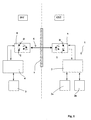
- FIG. 1 shows schematically an appendix 1 attached to the outside (EXT) of a vehicle (not shown).
- This an additional device 1 comprises two members 2a, 2b connected to an electronic housing 3 which controls their operation.
- the ancillary device may be for example a demining device comprising two coils 2a and 2b.
- the ancillary device could be a device for active defense comprising two response modules 2a, 2b.
- This ancillary device must be able to be ordered and controlled from inside the vehicle (INT).
- control another electronic housing 4 (called control) is arranged inside the vehicle.
- the control box 4 is optionally connected to a control device 5, also internal to the vehicle, by example to an on-board computer or to a driving shot (in the case of the riposte module command).
- the electronic housing external 3 (called controlled box) can exchange data with the electronic control unit 4.
- Data transmission is in the form of light signals 6 through at least one wall transparent 7.
- the transmission device comprises a first transmitter / receiver means 8, connected to the electronic control unit 4, and which is disposed inside (INT) of the vehicle.
- the device also includes a second means optical transceiver 9 connected to the electronic housing ordered 3, and which is arranged outside (EXT) of the vehicle.
- EXT outside
- the optical transceiver means are conventional and well known to those skilled in the art. These means comprise generally a transmitting diode D and a phototransistor T. receiver
- the first 8 and second 9 optical transceivers are arranged one for each to each other so that they can exchange their signals through the transparent wall 7.
- the transparent wall 7 is an element of the vehicle of which the invention simply takes advantage.
- Transparent walls such as windows or windshields are present on all the vehicles to allow the crew to see to outside.
- the light signals used will be coded.
- Another advantage of the transmission device according to the invention is that it does not cause disturbances electromagnetic. Moreover the electric power necessary for its operation is reduced and the emission optical radiates little outside the necessary action area. If several vehicles are located close to each other others, so there is no interaction between different transmission devices according to the invention.
- the device will be defined in such a way that the light signals are emitted in a band of frequency outside the visible spectrum (length wavelength from 0.4 micrometers to 0.7 micrometers).
- An optical communication channel presents a great bandwidth (of the order of a few mega bits per second). It is therefore possible with the device according to the invention to transmit many analog signals or digital.
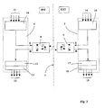
- Figure 3 thus shows in block diagram form the architecture of an electronics associated with the device according to the invention.
- the control box 4 contains means 10 ensuring the coding of signals 11 to be transmitted to the controlled housing external 3.
- These coding means are connected to the transmission channel E of the first optical transmitter / receiver means 8.
- the control box 4 also contains means 12 decoding the optical signal received by the first average transmitter / receiver 8 (reception channel R). These means decoding are coupled to detection means and error correction 13. Decoded and corrected signals received 14 are then transmitted to processing means (not shown)
- the coding means 10, decoding 12 and error detection / correction 13 will be carried out under the form of algorithms introduced into the memory of a microphone processor.
- the latter can advantageously be incorporated the on-board computer or another computer associated with the shooting conduct.
- Such coding and decoding means are in the field of data transmission.
- the box ordered 3 will contain (preferably in the form of put algorithms in memory in a micro processor) means 15 of coding of signals 16 to be transmitted to the internal control box 4, as well as means 17 for decoding the received optical signal by the second transmitter / receiver means 9.
- the decoding means 17 will be coupled to means for error detection and correction 18 and decoded signals and corrected receipts 19 will then be transmitted to treatment (not shown).
- Figure 2 shows a device according to another mode of embodiment of the invention.
- This device differs from that shown in Figure 1 in that the optical transceiver means 8 and 9 do not are more directly disposed towards each other than both sides of a transparent wall but are arranged indirectly facing each other, on both sides of an episcope 20.
- the episcope 20 is represented here schematically and its dimensions and proportions do not correspond of course not to those of a real episcope.
- Episcopes used in armored vehicles observe the outside of the vehicle following a actual viewing direction that is parallel to the direction of apparent observation of the gaze of the observer.
- an episcope 20 thus comprises two walls transparent 7a and 7b and two reflecting surfaces 21a and 21b.
- a light ray R1 emitted by the first means optical transceiver 8 is reflected on the surface 21a and returned according to R3.
- the radius R3 is reflected on the surface 21b and he comes out of the episcope 20 in one direction parallel to that of radius R1 (radius R2).
- the transmission device according to the invention is perfectly well adapted to a transmission through a episcope Signals are transmitted along paths optics perfectly controlled and which do not lead to loss of light power, so no loss of signal.
- the transmitter / receiver distance may seek to arrange the transmitter / receiver distance from the transparent wall (s) 7.
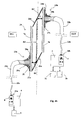
- FIG. 4a thus shows a similar embodiment to that of Figure 1, ie in which there is only one transparent wall 7 to cross with a signal luminous.
- Each transmitter / receiver 8 or 9 is thus connected to the wall 7 by an optical fiber 22a, 22b of which one end is fixed to the transparent wall 7 by a support means 23a, 23b.
- optical fibers 22a, 22b are connected to the associated transmitter / receiver means 8 or 9 by a connector 24a, 24b.
- optical fibers 22a, 22b arranged in the vicinity of the wall transparent 7.
- the optical fibers have a diameter of order of 0.5 mm with their external protective sheath 25 which surrounds a heart 26 of about 0.1mm in diameter. They occupy virtually no space at the level of the transparent wall 7 and do not interfere with normal vision at through the wall.
- each optical transceiver means 8 and 9 can then be integrated into its electronic housing 3 or 4.
- the embodiment of the device is thus simplified. All electronic components are integrated into the housings from which only optical fibers 22a, 22b to ensure the transmission of data. Fibers optics are space-saving and insensitive to electromagnetic radiation.
- Each support means 23a and 23b comprises a plate 27a, 27b which is fixed to the wall 7 by an adhesive layer 28a, 28b.
- the support means 23b comprises a connector 29b which allows the optical fiber to be tightly bonded to the plate 27b.
- the support means 23a also has a connector 29a ensuring a tight connection with the plate 27a.
- the support means thus make it possible to make the transmission of information. Indeed the portion of the wall transparent 7 which lies between the ends of the fibers 22a, 22b is then protected against moisture and dirt that is no longer likely to disturb the passage of optical signals from one fiber to another.
- This positioning can be achieved during the collage in implementing means for verifying the passage signals from one fiber to another.
- At the level of means support at least one means allowing a fine adjustment of the position of one optical fiber with respect to the other.
- FIG. 4a shows, at the level of the medium support 23a, an intermediate plate 30 which is fixed in an adjustable manner with respect to the glued plate 27a.
- the connector 29a is fixed to the intermediate plate 30.
- This intermediate plate must be able to be moved by relative to the plate 27a in at least two directions perpendicular to each other and parallel to the wall transparent. 7.
- the range of displacements to be provided for the plate 30 is reduced (less than the mm following the two perpendicular directions).
- the setting will be made in a simple way, for example by screws (not shown) flowing in lights (not shown) carried by the intermediate plate 30.
- FIG. 4b represents an assembly similar to that of the FIG. 4a but in which the wall 7 is replaced by a episcope 20. The operation is similar to that described previously with reference to Figure 2.
- the transparent wall 7a carries a support means 23a which again includes a plate 27a fixed by a layer of glue 28a and a connector 29a attached to a plate intermediate 30 allowing a fine adjustment of the position of the optical fiber 22a.
- the transparent wall 7b carries a support means 23b having a plate 27b fixed by a layer of glue 28b and a connector 29b.
- FIGS. 4a and 4b define fiber supports of different structure.
- optical fibers not by gluing but with a support bearing a sucker or with a mechanical support not crossing the wall transparent but permanently attached to this one containing means for receiving an optical fiber connector.
- the medium ensures watertightness by preventing moisture and dirt to cover the transparent wall between the ends of the optical fiber.
- the device according to the invention in a more compact way, it is also possible to implement the device according to the invention with several optical fibers arranged opposite one of the others on either side of a wall or an episcope.
- the fibers will advantageously be grouped together optical cables having a plurality of optical fibers.
- the invention can of course also be implemented work in another type of vehicle than an armored vehicle. It will thus be possible to implement the invention in the field naval or in the case of aircraft, whether these vehicles are civil or military.
Applications Claiming Priority (2)
| Application Number | Priority Date | Filing Date | Title |
|---|---|---|---|
| FR0402668 | 2004-03-12 | ||
| FR0402668A FR2867634B1 (fr) | 2004-03-12 | 2004-03-12 | Procede de transmission de donnees et dispositif mettant en oeuvre un tel procede |
Publications (1)
| Publication Number | Publication Date |
|---|---|
| EP1575191A1 true EP1575191A1 (de) | 2005-09-14 |
Family
ID=34814582
Family Applications (1)
| Application Number | Title | Priority Date | Filing Date |
|---|---|---|---|
| EP05290461A Withdrawn EP1575191A1 (de) | 2004-03-12 | 2005-03-02 | Verfahren zur Datenübertragung und Vorrichtung zum Ausführen dieses Verfahrens |
Country Status (2)
| Country | Link |
|---|---|
| EP (1) | EP1575191A1 (de) |
| FR (1) | FR2867634B1 (de) |
Citations (15)
| Publication number | Priority date | Publication date | Assignee | Title |
|---|---|---|---|---|
| US4192216A (en) * | 1978-02-10 | 1980-03-11 | Mason & Hanger-Silas Mason Co., Inc. | One-man armored vehicle |
| US4325146A (en) | 1979-12-20 | 1982-04-13 | Lennington John W | Non-synchronous object identification system |
| WO1987001538A1 (en) | 1985-09-05 | 1987-03-12 | Caterpillar Industrial Inc. | Optical communication apparatus for a vehicle |
| US4996719A (en) | 1988-02-26 | 1991-02-26 | Stanley Electric Co., Ltd. | Optical communication apparatus for motor vehicle |
| DE9315479U1 (de) | 1993-10-09 | 1994-01-05 | Tack Achim Dipl Ing | Einrichtung zur drahtlosen Übertragung von digitalen Signalen |
| US5315645A (en) | 1990-12-10 | 1994-05-24 | Tek Electronics Manufacturing Corporation | Communication apparatus utilizing digital optical signals |
| FR2701105A1 (fr) | 1993-02-01 | 1994-08-05 | Giat Ind Sa | Dispositif de déminage. |
| DE9416779U1 (de) * | 1994-10-18 | 1994-12-08 | Bosch Siemens Hausgeraete | Sensorgesteuerte Glaskeramik-Kochstelleneinheit |
| US5416627A (en) | 1988-09-06 | 1995-05-16 | Wilmoth; Thomas E. | Method and apparatus for two way infrared communication |
| DE19532679A1 (de) | 1995-09-05 | 1997-03-06 | Telefunken Microelectron | Optisches System |
| FR2750204A1 (fr) | 1996-06-19 | 1997-12-26 | Giat Ind Sa | Bobine de deminage et dispositif de deminage en faisant application |
| US5781125A (en) | 1995-08-12 | 1998-07-14 | Bayerische Motoren Werke Aktiengesellschaft | Arrangement for the wireless exchange of data between a servicing device and a control unit in a motor vehicle |
| EP1004844A1 (de) | 1998-11-23 | 2000-05-31 | Giat Industries | Aktivschutzvorrichtung für Fahrzeuge oder Strukturen |
| FR2805037A1 (fr) | 2000-02-10 | 2001-08-17 | Giat Ind Sa | Dispositif de protections d'une paroi |
| FR2838367A1 (fr) | 2002-04-16 | 2003-10-17 | Commissariat Energie Atomique | Systeme de transmission pour boite a gants |
-
2004
- 2004-03-12 FR FR0402668A patent/FR2867634B1/fr not_active Expired - Fee Related
-
2005
- 2005-03-02 EP EP05290461A patent/EP1575191A1/de not_active Withdrawn
Patent Citations (15)
| Publication number | Priority date | Publication date | Assignee | Title |
|---|---|---|---|---|
| US4192216A (en) * | 1978-02-10 | 1980-03-11 | Mason & Hanger-Silas Mason Co., Inc. | One-man armored vehicle |
| US4325146A (en) | 1979-12-20 | 1982-04-13 | Lennington John W | Non-synchronous object identification system |
| WO1987001538A1 (en) | 1985-09-05 | 1987-03-12 | Caterpillar Industrial Inc. | Optical communication apparatus for a vehicle |
| US4996719A (en) | 1988-02-26 | 1991-02-26 | Stanley Electric Co., Ltd. | Optical communication apparatus for motor vehicle |
| US5416627A (en) | 1988-09-06 | 1995-05-16 | Wilmoth; Thomas E. | Method and apparatus for two way infrared communication |
| US5315645A (en) | 1990-12-10 | 1994-05-24 | Tek Electronics Manufacturing Corporation | Communication apparatus utilizing digital optical signals |
| FR2701105A1 (fr) | 1993-02-01 | 1994-08-05 | Giat Ind Sa | Dispositif de déminage. |
| DE9315479U1 (de) | 1993-10-09 | 1994-01-05 | Tack Achim Dipl Ing | Einrichtung zur drahtlosen Übertragung von digitalen Signalen |
| DE9416779U1 (de) * | 1994-10-18 | 1994-12-08 | Bosch Siemens Hausgeraete | Sensorgesteuerte Glaskeramik-Kochstelleneinheit |
| US5781125A (en) | 1995-08-12 | 1998-07-14 | Bayerische Motoren Werke Aktiengesellschaft | Arrangement for the wireless exchange of data between a servicing device and a control unit in a motor vehicle |
| DE19532679A1 (de) | 1995-09-05 | 1997-03-06 | Telefunken Microelectron | Optisches System |
| FR2750204A1 (fr) | 1996-06-19 | 1997-12-26 | Giat Ind Sa | Bobine de deminage et dispositif de deminage en faisant application |
| EP1004844A1 (de) | 1998-11-23 | 2000-05-31 | Giat Industries | Aktivschutzvorrichtung für Fahrzeuge oder Strukturen |
| FR2805037A1 (fr) | 2000-02-10 | 2001-08-17 | Giat Ind Sa | Dispositif de protections d'une paroi |
| FR2838367A1 (fr) | 2002-04-16 | 2003-10-17 | Commissariat Energie Atomique | Systeme de transmission pour boite a gants |
Non-Patent Citations (1)
| Title |
|---|
| MATSUURA H: "Gunma prefecture's approaches for universal traffic management system (UTMS)", INTELLIGENT TRANSPORTATION SYSTEMS, 1999. PROCEEDINGS. 1999 IEEE/IEEJ/JSAI INTERNATIONAL CONFERENCE ON TOKYO, JAPAN 5-8 OCT. 1999, PISCATAWAY, NJ, USA,IEEE, US, 5 October 1999 (1999-10-05), pages 212 - 217, XP010369857, ISBN: 0-7803-4975-X * |
Also Published As
| Publication number | Publication date |
|---|---|
| FR2867634B1 (fr) | 2008-07-04 |
| FR2867634A1 (fr) | 2005-09-16 |
Similar Documents
| Publication | Publication Date | Title |
|---|---|---|
| EP1341013B1 (de) | Optische Drehverbindung | |
| FR2622705A1 (fr) | Tete de detecteur optique grand angle | |
| FR2916283A1 (fr) | Connecteur de fibre optique, inserts a contact actif pour connecteur de fibre optique et procede de fabrication | |
| FR2494454A1 (fr) | Connecteur de cable sismique muni d'un transducteur optique | |
| EP0104987B1 (de) | Head-up Visier verwendet als Zielvorrichtung | |
| EP0206901B1 (de) | Anordnung zur Steuerung und Überwachung einer industriellen Anlage durch optische Übertragung von Nachrichten und Befehlen | |
| FR2476326A1 (fr) | Dispositif pour determiner la position angulaire d'une cible eclairee par des impulsions lumineuses | |
| FR2588387A1 (fr) | Element de connecteur hermaphrodite pour fibres optiques | |
| EP1575191A1 (de) | Verfahren zur Datenübertragung und Vorrichtung zum Ausführen dieses Verfahrens | |
| EP0702246A1 (de) | Tragbares Gerät zum Messen der Rückstreuung von Licht | |
| FR2530009A1 (fr) | Appareil de visee panoramique stabilisee comprenant un detecteur thermique | |
| FR2552893A1 (fr) | Perfectionnements aux appareils d'observation | |
| CA3128728C (fr) | Injection d'un faisceau de rayonnement dans une fibre optique | |
| FR2509479A1 (fr) | Dispositif d'emission-reception d'energie radiante et systeme de liaison bidirectionnelle par fibre optique comprenant un tel dispositif | |
| FR2831344A1 (fr) | Systeme de distribution d'alimentation fonde sur un conduit de communication a lumiere | |
| EP0068932A1 (de) | Zielköpfe bei periskopischen Einrichtungen, insbesondere für Unterseeboote | |
| EP3402096B1 (de) | Kompaktes fsoi-modul, das widerstandsfähig gegen schwierige umweltbedingungen ist | |
| FR2548384A1 (fr) | Dispositif a imagerie video, notamment pour autodirecteur | |
| FR2679436A1 (fr) | Systeme de radiographie computerise. | |
| EP2232307B1 (de) | Laserzeigesystem | |
| EP0487391A1 (de) | Mehrwegiger bidirektionaler optischer Sende- und Empfangsmodul und diesen verwendende Relaisstation | |
| FR2509034A1 (fr) | Viseur periscopique protege | |
| FR2469705A1 (fr) | Procede et dispositif de verification d'appareils opto-electroniques | |
| FR2594535A1 (fr) | Dispositif de telemetrie optique | |
| FR2669483A1 (fr) | Systeme de multiplexage optique bi-directionnel et procede correspondant. |
Legal Events
| Date | Code | Title | Description |
|---|---|---|---|
| PUAI | Public reference made under article 153(3) epc to a published international application that has entered the european phase |
Free format text: ORIGINAL CODE: 0009012 |
|
| AK | Designated contracting states |
Kind code of ref document: A1 Designated state(s): AT BE BG CH CY CZ DE DK EE ES FI FR GB GR HU IE IS IT LI LT LU MC NL PL PT RO SE SI SK TR |
|
| AX | Request for extension of the european patent |
Extension state: AL BA HR LV MK YU |
|
| 17P | Request for examination filed |
Effective date: 20060220 |
|
| AKX | Designation fees paid |
Designated state(s): AT BE BG CH CY CZ DE DK EE ES FI FR GB GR HU IE IS IT LI LT LU MC NL PL PT RO SE SI SK TR |
|
| RAP1 | Party data changed (applicant data changed or rights of an application transferred) |
Owner name: NEXTER SYSTEMS |
|
| 17Q | First examination report despatched |
Effective date: 20090212 |
|
| GRAP | Despatch of communication of intention to grant a patent |
Free format text: ORIGINAL CODE: EPIDOSNIGR1 |
|
| RIN1 | Information on inventor provided before grant (corrected) |
Inventor name: LAINE, LOIC M. |
|
| STAA | Information on the status of an ep patent application or granted ep patent |
Free format text: STATUS: THE APPLICATION HAS BEEN WITHDRAWN |
|
| 18W | Application withdrawn |
Effective date: 20120131 |