EP1575108A1 - Fuel cell assembly and method for controlling reaction equilibrium - Google Patents
Fuel cell assembly and method for controlling reaction equilibrium Download PDFInfo
- Publication number
- EP1575108A1 EP1575108A1 EP05013024A EP05013024A EP1575108A1 EP 1575108 A1 EP1575108 A1 EP 1575108A1 EP 05013024 A EP05013024 A EP 05013024A EP 05013024 A EP05013024 A EP 05013024A EP 1575108 A1 EP1575108 A1 EP 1575108A1
- Authority
- EP
- European Patent Office
- Prior art keywords
- fuel cell
- cell elements
- flow
- cross sectional
- sectional area
- Prior art date
- Legal status (The legal status is an assumption and is not a legal conclusion. Google has not performed a legal analysis and makes no representation as to the accuracy of the status listed.)
- Withdrawn
Links
- 239000000446 fuel Substances 0.000 title claims abstract description 112
- 238000006243 chemical reaction Methods 0.000 title claims abstract description 26
- 238000000034 method Methods 0.000 title claims description 6
- 230000007423 decrease Effects 0.000 claims description 2
- 125000006850 spacer group Chemical group 0.000 description 27
- 239000007789 gas Substances 0.000 description 21
- 239000000047 product Substances 0.000 description 20
- 239000000376 reactant Substances 0.000 description 18
- 239000003792 electrolyte Substances 0.000 description 13
- 239000000203 mixture Substances 0.000 description 13
- 230000008859 change Effects 0.000 description 9
- 239000007772 electrode material Substances 0.000 description 7
- QVGXLLKOCUKJST-UHFFFAOYSA-N atomic oxygen Chemical compound [O] QVGXLLKOCUKJST-UHFFFAOYSA-N 0.000 description 6
- 239000002001 electrolyte material Substances 0.000 description 6
- 239000001301 oxygen Substances 0.000 description 6
- 229910052760 oxygen Inorganic materials 0.000 description 6
- 230000003247 decreasing effect Effects 0.000 description 5
- 239000010411 electrocatalyst Substances 0.000 description 5
- ATUOYWHBWRKTHZ-UHFFFAOYSA-N Propane Chemical compound CCC ATUOYWHBWRKTHZ-UHFFFAOYSA-N 0.000 description 4
- 239000010405 anode material Substances 0.000 description 4
- 239000010406 cathode material Substances 0.000 description 4
- 229910021526 gadolinium-doped ceria Inorganic materials 0.000 description 4
- VNWKTOKETHGBQD-UHFFFAOYSA-N methane Chemical compound C VNWKTOKETHGBQD-UHFFFAOYSA-N 0.000 description 4
- BASFCYQUMIYNBI-UHFFFAOYSA-N platinum Chemical compound [Pt] BASFCYQUMIYNBI-UHFFFAOYSA-N 0.000 description 4
- 229910002449 CoO3−δ Inorganic materials 0.000 description 3
- 239000006227 byproduct Substances 0.000 description 3
- 238000013461 design Methods 0.000 description 3
- 230000007246 mechanism Effects 0.000 description 3
- 239000007800 oxidant agent Substances 0.000 description 3
- 229910001233 yttria-stabilized zirconia Inorganic materials 0.000 description 3
- MYMOFIZGZYHOMD-UHFFFAOYSA-N Dioxygen Chemical compound O=O MYMOFIZGZYHOMD-UHFFFAOYSA-N 0.000 description 2
- PXHVJJICTQNCMI-UHFFFAOYSA-N Nickel Chemical compound [Ni] PXHVJJICTQNCMI-UHFFFAOYSA-N 0.000 description 2
- WUKWITHWXAAZEY-UHFFFAOYSA-L calcium difluoride Chemical group [F-].[F-].[Ca+2] WUKWITHWXAAZEY-UHFFFAOYSA-L 0.000 description 2
- 238000004891 communication Methods 0.000 description 2
- 229910001882 dioxygen Inorganic materials 0.000 description 2
- 238000005516 engineering process Methods 0.000 description 2
- 238000004519 manufacturing process Methods 0.000 description 2
- 239000000463 material Substances 0.000 description 2
- 238000012986 modification Methods 0.000 description 2
- 230000004048 modification Effects 0.000 description 2
- 229910052697 platinum Inorganic materials 0.000 description 2
- UFHFLCQGNIYNRP-UHFFFAOYSA-N Hydrogen Chemical compound [H][H] UFHFLCQGNIYNRP-UHFFFAOYSA-N 0.000 description 1
- 229910052772 Samarium Inorganic materials 0.000 description 1
- NASIAHACWQWMAF-UHFFFAOYSA-N [Co]=O.[La].[Ba] Chemical compound [Co]=O.[La].[Ba] NASIAHACWQWMAF-UHFFFAOYSA-N 0.000 description 1
- HHWBWNRYGPXTSW-UHFFFAOYSA-N [Co]=O.[Sr].[Gd] Chemical compound [Co]=O.[Sr].[Gd] HHWBWNRYGPXTSW-UHFFFAOYSA-N 0.000 description 1
- OQKOQEWPYHIUMN-UHFFFAOYSA-N [Sr].[Co]=O.[Sm] Chemical compound [Sr].[Co]=O.[Sm] OQKOQEWPYHIUMN-UHFFFAOYSA-N 0.000 description 1
- 230000001133 acceleration Effects 0.000 description 1
- 230000004075 alteration Effects 0.000 description 1
- 239000000919 ceramic Substances 0.000 description 1
- 229910021525 ceramic electrolyte Inorganic materials 0.000 description 1
- 229910000422 cerium(IV) oxide Inorganic materials 0.000 description 1
- 239000011195 cermet Substances 0.000 description 1
- 239000007795 chemical reaction product Substances 0.000 description 1
- 238000009826 distribution Methods 0.000 description 1
- -1 e.g. Chemical compound 0.000 description 1
- 230000005611 electricity Effects 0.000 description 1
- 238000003487 electrochemical reaction Methods 0.000 description 1
- 239000010436 fluorite Substances 0.000 description 1
- 239000002737 fuel gas Substances 0.000 description 1
- XLYOFNOQVPJJNP-ZSJDYOACSA-N heavy water Substances [2H]O[2H] XLYOFNOQVPJJNP-ZSJDYOACSA-N 0.000 description 1
- 239000001257 hydrogen Substances 0.000 description 1
- 229910052739 hydrogen Inorganic materials 0.000 description 1
- 230000001788 irregular Effects 0.000 description 1
- 229910052751 metal Inorganic materials 0.000 description 1
- 239000002184 metal Substances 0.000 description 1
- 229910052759 nickel Inorganic materials 0.000 description 1
- 229910002119 nickel–yttria stabilized zirconia Inorganic materials 0.000 description 1
- 238000005457 optimization Methods 0.000 description 1
- 230000003647 oxidation Effects 0.000 description 1
- 238000007254 oxidation reaction Methods 0.000 description 1
- 239000005518 polymer electrolyte Substances 0.000 description 1
- 239000001294 propane Substances 0.000 description 1
- 230000009467 reduction Effects 0.000 description 1
- 238000011160 research Methods 0.000 description 1
- 238000012827 research and development Methods 0.000 description 1
- KZUNJOHGWZRPMI-UHFFFAOYSA-N samarium atom Chemical compound [Sm] KZUNJOHGWZRPMI-UHFFFAOYSA-N 0.000 description 1
- 229910052709 silver Inorganic materials 0.000 description 1
- 239000004332 silver Substances 0.000 description 1
- 239000007787 solid Substances 0.000 description 1
Images


Classifications
-
- F—MECHANICAL ENGINEERING; LIGHTING; HEATING; WEAPONS; BLASTING
- F16—ENGINEERING ELEMENTS AND UNITS; GENERAL MEASURES FOR PRODUCING AND MAINTAINING EFFECTIVE FUNCTIONING OF MACHINES OR INSTALLATIONS; THERMAL INSULATION IN GENERAL
- F16H—GEARING
- F16H59/00—Control inputs to control units of change-speed- or reversing-gearings for conveying rotary motion
- F16H59/02—Selector apparatus
- F16H59/0204—Selector apparatus for automatic transmissions with means for range selection and manual shifting, e.g. range selector with tiptronic
-
- H—ELECTRICITY
- H01—ELECTRIC ELEMENTS
- H01M—PROCESSES OR MEANS, e.g. BATTERIES, FOR THE DIRECT CONVERSION OF CHEMICAL ENERGY INTO ELECTRICAL ENERGY
- H01M8/00—Fuel cells; Manufacture thereof
- H01M8/04—Auxiliary arrangements, e.g. for control of pressure or for circulation of fluids
- H01M8/04082—Arrangements for control of reactant parameters, e.g. pressure or concentration
- H01M8/04089—Arrangements for control of reactant parameters, e.g. pressure or concentration of gaseous reactants
-
- F—MECHANICAL ENGINEERING; LIGHTING; HEATING; WEAPONS; BLASTING
- F16—ENGINEERING ELEMENTS AND UNITS; GENERAL MEASURES FOR PRODUCING AND MAINTAINING EFFECTIVE FUNCTIONING OF MACHINES OR INSTALLATIONS; THERMAL INSULATION IN GENERAL
- F16H—GEARING
- F16H59/00—Control inputs to control units of change-speed- or reversing-gearings for conveying rotary motion
- F16H59/02—Selector apparatus
- F16H59/0278—Constructional features of the selector lever, e.g. grip parts, mounting or manufacturing
-
- H—ELECTRICITY
- H01—ELECTRIC ELEMENTS
- H01M—PROCESSES OR MEANS, e.g. BATTERIES, FOR THE DIRECT CONVERSION OF CHEMICAL ENERGY INTO ELECTRICAL ENERGY
- H01M8/00—Fuel cells; Manufacture thereof
- H01M8/02—Details
- H01M8/0202—Collectors; Separators, e.g. bipolar separators; Interconnectors
- H01M8/0258—Collectors; Separators, e.g. bipolar separators; Interconnectors characterised by the configuration of channels, e.g. by the flow field of the reactant or coolant
- H01M8/0265—Collectors; Separators, e.g. bipolar separators; Interconnectors characterised by the configuration of channels, e.g. by the flow field of the reactant or coolant the reactant or coolant channels having varying cross sections
-
- H—ELECTRICITY
- H01—ELECTRIC ELEMENTS
- H01M—PROCESSES OR MEANS, e.g. BATTERIES, FOR THE DIRECT CONVERSION OF CHEMICAL ENERGY INTO ELECTRICAL ENERGY
- H01M8/00—Fuel cells; Manufacture thereof
- H01M8/24—Grouping of fuel cells, e.g. stacking of fuel cells
- H01M8/241—Grouping of fuel cells, e.g. stacking of fuel cells with solid or matrix-supported electrolytes
- H01M8/2425—High-temperature cells with solid electrolytes
-
- H—ELECTRICITY
- H01—ELECTRIC ELEMENTS
- H01M—PROCESSES OR MEANS, e.g. BATTERIES, FOR THE DIRECT CONVERSION OF CHEMICAL ENERGY INTO ELECTRICAL ENERGY
- H01M8/00—Fuel cells; Manufacture thereof
- H01M8/24—Grouping of fuel cells, e.g. stacking of fuel cells
- H01M8/2465—Details of groupings of fuel cells
-
- F—MECHANICAL ENGINEERING; LIGHTING; HEATING; WEAPONS; BLASTING
- F16—ENGINEERING ELEMENTS AND UNITS; GENERAL MEASURES FOR PRODUCING AND MAINTAINING EFFECTIVE FUNCTIONING OF MACHINES OR INSTALLATIONS; THERMAL INSULATION IN GENERAL
- F16H—GEARING
- F16H59/00—Control inputs to control units of change-speed- or reversing-gearings for conveying rotary motion
- F16H59/02—Selector apparatus
- F16H59/0278—Constructional features of the selector lever, e.g. grip parts, mounting or manufacturing
- F16H2059/0282—Lever handles with lock mechanisms, e.g. for allowing selection of reverse gear or releasing lever from park position
-
- Y—GENERAL TAGGING OF NEW TECHNOLOGICAL DEVELOPMENTS; GENERAL TAGGING OF CROSS-SECTIONAL TECHNOLOGIES SPANNING OVER SEVERAL SECTIONS OF THE IPC; TECHNICAL SUBJECTS COVERED BY FORMER USPC CROSS-REFERENCE ART COLLECTIONS [XRACs] AND DIGESTS
- Y02—TECHNOLOGIES OR APPLICATIONS FOR MITIGATION OR ADAPTATION AGAINST CLIMATE CHANGE
- Y02E—REDUCTION OF GREENHOUSE GAS [GHG] EMISSIONS, RELATED TO ENERGY GENERATION, TRANSMISSION OR DISTRIBUTION
- Y02E60/00—Enabling technologies; Technologies with a potential or indirect contribution to GHG emissions mitigation
- Y02E60/30—Hydrogen technology
- Y02E60/50—Fuel cells
Definitions
- the present invention generally relates to fuel cells.
- Fuel cell technology is of particular commercial interest. Ongoing research and development continues to further the scope of potential uses of this technology. Fuel cell efficiency is one area of research that has a substantial amount of potential for advancement. Fuel cells use chemical reactions to convert fuels and oxidizers to products and/or by products and electricity. The efficiency of a fuel cell then is linked to the numerous factors associated with the reactant contact-time and pressure at an electrocatalyst, optimizing the reaction equilibrium and creating conditions that favor the complete conversion to reaction products and/or by-products.
- One factor related to fuel cell efficiency may be how well the fuel is utilized by the fuel cell.
- the fuel utilization may depend upon shifts in the reaction equilibrium. If the reaction equilibrium shifts toward the reactants, the fuel may be under utilized, i . e ., less fuel may be converted to products. Shifts in the reaction equilibrium may depend upon the apparatus and/or the operating conditions of the fuel cell. Alterations in the apparatus and/or operating conditions may prevent undesirable shifts in the reaction equilibrium.
- the space velocity of fuel and oxidizer control factors e.g., electrocatalyst contact time, reactant pressure, strongly influence the conversion efficiency and fuel utilization of the fuel cell system. The subject matter described below addresses one or more of these issues.
- a fuel cell assembly may comprise one or more fuel cell elements and one or more flow passageways in contact with fuel cell elements wherein at least a portion of the cross sectional area of a flow passageway is graduated.
- a fuel cell assembly may comprise flow passageways that have a region of graduated cross sectional area for maintaining or shifting the reaction equilibrium.
- the regions may be defined by the arrangement of stacked fuel cell elements alone or in combination with additional shaped spacers.
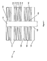
- FIG. 1 shows a fuel cell assembly using spacers in the cathode passageways in accordance with the various embodiments of the invention
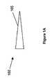
- Figure 1 a shows a fuel cell spacer having a textured surface
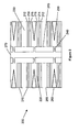
- FIG. 2 shows a fuel cell assembly using spacers in the anode passageways in accordance with the various embodiments of the invention
- FIG. 3 shows a fuel cell assembly without spacers in accordance with the various embodiments of the invention.
- FIG. 4 shows a fuel cell assembly using spacers in the anode and cathode passageways in accordance with the various embodiments of the invention.
- Embodiments of the invention may indude a fuel cell assembly comprising one or more fuel cell elements and one or more flow passageways in contact with fuel cell elements wherein at least a portion of the cross sectional area of a flow passageway is graduated.
- a flow passageway is graduated in order to change the cross sectional area along the flow passageway. It will be understood that a change in the cross sectional area may correspond to a change in volume along the passageway. The change in volume along the passageway may affect the velodty of the flowing gas stream, which may affect the pressure at the side walls within the passageway ( i . e ., the pressure of the reactant spedes at the electrocatalyst).
- the relevant reaction at the cathode side of a fuel cell is diatomic molecular oxygen converting to ionic oxygen.
- the relevant pressures involved are the pressures of oxygen on both sides of the equation. In order to favor products a greater pressure may be necessary on the reactant side of the equation.
- the chamber was expanding along the passageway, i . e ., volume increasing, the gas may have a lower velocity resulting in a higher pressure at the cathode surface. Accordingly, an expanding cathode passageway may help maintain reaction equilibrium or create a shift that favors the production of ionic oxygen.
- the relevant reaction is between the ionic oxygen and a fuel, e.g., C 3 H 8 , CH 4 , H 2 , and the like.
- a fuel e.g., C 3 H 8 , CH 4 , H 2 , and the like.
- the reactants enter the anode chamber they begin to react and form products. More and more product is formed along the flow path within the flow passageway. The result is that the pressure of the products may be increasing along the flow passageway. Accordingly, if the flow passageway were contracting, i . e ., the volume within the chamber was decreasing, the velocity of the gas may increase resulting in a lower pressure of products at the anode surface. The lowered pressure on the product side may help maintain reaction equilibrium or create a shift that favors products.
- An additional consideration in selecting an appropriate reduction in volume may be the fuel composition.
- different fuel compositions may result in different volumes of products being formed.
- a similar reaction using one mole of methane results in only three moles of products and only one mole of products for one mole of hydrogen fuel. Accordingly, it may be appropriate to consider the fuel composition when determining a change in volume along an anode passageway.
- Various embodiments are contemplated as suitable for varying the volume of the flow passageways including, but not limited to, alignment of the fuel cell elements, the inclusion of fuel cell spacers, or some combination thereof.
- a fuel cell assembly 100 is shown comprised of fuel cell elements 110 and flow passageways 120, 130 each having an inlets 140, 145 and outlets 150, 155 and spacers 160.
- the adjacent fuel cell elements 110 form at least in part the boundaries of flow passageways 120, while other flow passageways 130 are defined by both adjacent fuel cell elements 110 and spacers 160.
- the fuel cell elements have a central throughbore 170 that allows communication with flow passageways 120, 130 as a mechanism to remove gas via outlets 150, 155.
- the flow may be a counterflow, i . e ., flow passageways 120 have a flow from ports 140, to ports 150, while flow passageways 130 have flow from ports 155 to ports 145 or vica versa depending upon the direction of the graduated volume within the cathode passageway.
- the fuel cell elements 110 may be comprised of electrode and electrolyte material. It will be appreciated that the particular electrolyte material used in the embodiments of the invention is not critical to the spirit of the invention.
- the electrolyte material may be formed from any suitable material, as desired and/or necessitated by a particular end use. Suitable electrolyte materials may include, but are not limited to, cubic fluorite structure electrolytes, doped cubic fluorite electrolytes, proton-exchange polymer electrolytes, proton-exchange ceramic electrolytes, and mixtures thereof.
- the electrolyte material may be yttria-stabilized zirconia (YSZ), samarium doped-ceria (SDC, Ce x Sm y O 2- ⁇ ), gadolinium doped-ceria (GDC, Ce x Gd y O 2- ⁇ ), La a Sr b Ga c Mg d O 3- ⁇ and mixtures thereof.
- YSZ yttria-stabilized zirconia
- SDC samarium doped-ceria
- GDC gadolinium doped-ceria
- La a Sr b Ga c Mg d O 3- ⁇ and mixtures thereof.
- the electrode material used in the embodiments of the invention is not critical to the spirit of the invention.
- the electrode material may be formed from any suitable material, as desired and/or necessitated by a particular end use.
- the electrode materials may be comprised of metal(s), ceramic(s) and/or cermet(s).
- the electrode materials may comprise either anode or cathode materials.
- suitable anode materials include, but are not limited to, nickel, platinum, Ni-YSZ, Cu-YSZ, Ni-SDC, Ni-GDC, Cu-SDC, Cu-GDC and mixtures thereof.
- cathode materials include, but are not limited to, silver, platinum and mixtures thereof; and samarium strontium cobalt oxide (SSCO, Sm x Sr y CoO 3- ⁇ ), barium lanthanum cobalt oxide (BLCO, Ba x La y CoO 3- ⁇ ), gadolinium strontium cobalt oxide (GSCO, Gd x Sr y CoO 3- ⁇ ) and mixtures thereof.
- SSCO samarium strontium cobalt oxide
- BLCO barium lanthanum cobalt oxide
- GSCO gadolinium strontium cobalt oxide
- the fuel cell elements 110 may be configured as electrolyte supported elements having an anode layer 112, a cathode layer 116 and an electrolyte layer 114 disposed between the anode 112 and cathode 116 layers. It should be appreciated that this configuration is not critical to the invention and other configurations of fuel cell elements are within the scope of the invention.
- the fuel cell elements 110 may have an electrode supported configuration, in which the anode is the support and the electrolyte and cathode materials are deposited as thin layers on the anode material.
- each of the fuel cell elements 110 have a similar anode/electrolyte/cathode structure or order, but the order of the layers is reversed for each successive element.
- the fuel cell elements 110 are stacked in an anode to anode and cathode to cathode arrangement. In this type of arrangement, flow passageways 120 and 130 may become anode passageways 120 and cathode passageways 130.
- the fuel cell elements 110 may have any shape. Although not illustrated, the fuel cell elements 110 in Figure 1 are contemplated as having a generally planar disc shape. Planar square, rectangular or other shapes are equally applicable. The shape may be selected as desired and/or necessitated by a particular end use. In addition, depending upon the ultimate shape design selected, the flow passageway inner and outer ports may be located at differing regions of the fuel cell element.
- the spacers 160 may be disposed selectively within one or more flow passageways.
- Spacers 160 may have any suitable shape such that the spacers may be mounted within the assembly 100 and have an appropriate distribution over the available electrode surface area within a flow passageway.
- the shape of the spacers 160 may correspond to the planar shape (regardless of cross sectional shape) of the fuel cell elements 110. In other words, if the fuel cell elements 110 had a planar circular shape then the spacer may also have a planar circular shape.
- Spacers 160 may be used to adjust the volume within the flow passageway and, thus, may have a graduated region that increases in thickness along the outward flow path within the flow passageways 130. The cross section of the graduated region may resemble a wedge shape, as shown in Figure 1.
- spacers 160 may also have textured surfaces 165, as shown in Figure 1 a.
- the textured surface 165 may simply be irregular or may have some type of designed grooves or ridges. Textured surfaces 165 may disrupt gas flow within the flow passageways and cause increased turbulence, which may increase the probability of the reactant gas stream interacting with the electrode material.
- the textured surfaces may force the gas stream to move in a designed pattern, e.g., spiral or rotational, as it moves from inlet to outlet within a flow passageway. Forced flow may also increase the residence time of the reactant gas within the flow passageways providing an increased probability of the reactant gas stream interacting with the electrode material.
- the graduated regions may be located within the anode passageways.
- Figure 2 shows a fuel cell assembly 200 is comprised of solid oxide fuel cell elements 210; and flow passageways 220, 230 each having inner ports 240, 245 and outer ports 250, 255 and spacers 260.
- the adjacent fuel cell elements 210 form at least in part the boundaries of flow passageways 230, while other flow passageways 220 are defined by both adjacent fuel cell elements 210 and spacers 260.
- the fuel cell elements have a central throughbore 270 that allows communication with the flow passageways 220, 230 as either a mechanism to introduce gas via inlets 240, 245.
- fuel cell elements 210 may be configured as electrolyte supported elements having an anode layer 212, a cathode layer 216 and an electrolyte layer 214 disposed between the anode 212 and cathode 216 layers.
- Each of the fuel cell elements 210 have a similar anode%lectrolyte%athode structure or order, but the order of the layers is reversed for each successive element.
- the fuel cell elements 210 are stacked in an anode to anode and cathode to cathode arrangement.
- the considerations for the fuel cell assembly 200 are the same as those disclosed in the description above with respect to the fuel cell assembly 100 in Figure 1 (e.g ., electrode composition and configuration, spacer composition and configuration, and the like).
- the difference in fuel cell assembly 200 is placement of the spacers 260 within the anode passageways 220 instead of within the cathode passageways 230 as in assembly 100.
- the flow of gas through the flow passageways 220 and 230 flows from ports 240, 245 located near the inner or central region of the fuel cell elements 210 to ports 250, 255 located near the outer or periphery region of the fuel cell elements 210.
- Inlets 240, 245 feed to a common throughbore 270 as a mechanism to introduce gas from flow passageways 220, 230.
- the flow may be a counterflow with respect to the anode passageway 220 and cathode passageways 230, i . e ., anode flow from outer to inner region and cathode flow from inner region to outer region or, vice versa depending upon the direction of the graduated volume within the anode passageway.
- FIG 3 shows another embodiment of a fuel cell assembly 300 having a plurality of fuel cell elements 310 and flow passageways 320 each having an inlet 330 and outlet 340.
- the fuel cell elements 310 may be configured as electrolyte supported elements having an anode layer 312, a cathode layer 316 and an electrolyte layer 314 disposed between the anode 312 and cathode 316 layers.
- this particular fuel cell element configuration is not critical to the invention and other configurations of fuel cell elements are within the scope of the invention.
- the fuel cell elements 310 are stacked in an anode to anode and cathode to cathode arrangement. In this type of arrangement, flow passageways 320 may become anode or cathode chambers.
- the fuel cell elements 310 may have any suitable shape, e.g. , square, rectangular, triangular or any combination thereof. The shape may be selected as desired and/or necessitated by a particular end use. Although not illustrated, the fuel cell elements 310 in Figure 2 are contemplated as having a planar square or rectangular shape. The adjacent fuel cell elements 310 form at least in part the boundaries of flow passageways 320.
- the flow passageways 320 have a graduated or non-constant cross sectional volume.
- the graduated cross sectional area of the flow passageways 320 is formed by non-parallel alignment of adjacent fuel cell elements 310.
- the degree of volume change along the flow passageways 320 may be tailored to correspond to a particular fuel composition or other consideration by changing the alignment of the fuel cell elements 310 with respect to each other.
- FIG. 4 shows another embodiment of a fuel cell assembly 400 having a plurality of fuel cell elements 410, flow passageways 420, 425 each having an inlet 430, 435 and an outlet 440, 445 and spacers 450, 460.
- the fuel cell elements 410 may be configured as electrolyte supported having an anode layer 412, a cathode layer 416 and an electrolyte layer 414.
- the adjacent fuel cell elements 410 form at least in part the boundaries of flow passageways 420, 425 along with spacers 450, 460.
- Spacers 450, 460 have a region of graduated cross sectional area resembling a wedge shape.
- the spacers in 450 and 460 may or may not be identical in shape, cross sectional area or composition.
- the volume change for an anode passageway 425 may require a different change in volume due to any number of factors induding, but not limited to, the fuel being used.
- the flow may be counterflow with respect to the flow passageways 420 and 425 provided that the flow chambers expand along the flow path regardless of direction of flow.
- One embodiment is directed toward a method to increase fuel cell efficiency.
- the method comprises the steps of accessing a fuel cell stack comprising fuel cell elements, each element comprising an anode, a cathode and an electrolyte disposed between the anode and cathode.
- the fuel cell elements may define at least in part flow passageways between the elements.
- the flow passageways should have a region of graduated cross sectional area along the flow path defined by the flow passageway.
- the region of graduated cross sectional area may be accomplished within the flow passageway by alignment of the fuel cell elements engaged in an assembly and/or using spacers.
- the spacers will be disposed between adjacent fuel cell elements and have at least region of graduated thickness.
- a gas stream is then passed through a flow passageway allowing at least a portion of the gas to contact with anode or cathode material, depending upon the passageway.
- an oxygen containing gas may pass over a cathode and a fuel gas over an anode.
- the gas will pass through the passageway and the region of graduated cross sectional area having an affect on the velocity and pressure in that region.
- the volume adjustment can be tailored to a particular fuel as described earlier, to compensate for the inherent structure of the fuel cell elements and arrangement of the stack, and/or to compensate for the consumption of reactant gas or production of products along the flow passageway.
- the volume of the passageway is controlled and the reaction equilibrium, electrocatalyst contact time and/or reactant pressure may be optimized.
- inventions of this present invention may indude fuel cell systems that combine a mixture of the fuel and oxidizer into the fuel cell chamber.
- This is commonly called a single-chamber design, where the selectivvities of the respective anode and cathode only allow the appropriate oxidation and reducing reactions to take place, respectively.
- the anode and cathode can be disposed on opposite sides and/or the same side of the electrolyte.
- the volume of the passageways can be adjusted using the methods described above, although the optimized values of the velocity of the gases may be slightly different due to the conversion of the respective fuel and oxidizer to products and/or by-products in the same flow passage.
Landscapes
- Engineering & Computer Science (AREA)
- Life Sciences & Earth Sciences (AREA)
- Manufacturing & Machinery (AREA)
- Sustainable Development (AREA)
- Sustainable Energy (AREA)
- Chemical & Material Sciences (AREA)
- Chemical Kinetics & Catalysis (AREA)
- Electrochemistry (AREA)
- General Chemical & Material Sciences (AREA)
- General Engineering & Computer Science (AREA)
- Mechanical Engineering (AREA)
- Fuel Cell (AREA)
Abstract
Description
Claims (8)
- A fuel cell assembly (100), comprising:wherein at least one flow passageway has a cross sectional area that is graduated, wherein the graduated cross sectional area is formed at least in part by non-parallel alignment of the adjacent fuel cell elements (310).one or more fuel cell elements (110); andone or more flow passageways (120, 130) from an inlet (140, 145) to an outlet (150, 155) between adjacent fuel cell elements (110);
- The assembly according to claim 1 wherein the fuel cell elements (110) have a planar disc shape.
- The assembly according to claim 1 wherein the fuel cell elements (110) have either a square or rectangular shape.
- The assembly according to any one of claims 1 to 3, wherein the at least one flow passageway is configured to feed gas introduced into the inlet to the first and the second fuel cell elements.
- The assembly according to any one of claims 1 to 4, wherein the cross sectional area increases from the inlet towards the outlet.
- The assembly according to any one of claims 1 to 4, wherein the cross sectional area decreases from the inlet towards the outlet.
- The assembly according to any one of claims 1 to 6, the assembly comprising first and second flow passageways (120, 130) each having a cross sectional area that is graduated, wherein the first flow passageway (120, 130) is adapted for feeding gas to electrodes of the fuel cell elements and the second flow passageway (120, 130) is adapted for feeding gas to cathodes of the fuel cell elements.
- A method to increase fuel cell efficiency, comprising:passing a gas stream through a flow passageway (130) having a region of graduated cross sectional area along the flow passageway (130), wherein the graduated cross sectional area is formed at least in part by non-parallel alignment of fuel cell elements (310), wherein the pressure along the flow passageway (130) is controlled and the reaction equilibrium is maintained.
Applications Claiming Priority (3)
| Application Number | Priority Date | Filing Date | Title |
|---|---|---|---|
| US428296 | 1999-10-27 | ||
| US10/428,296 US20040219418A1 (en) | 2003-04-30 | 2003-04-30 | Fuel cell assembly and method for controlling reaction equilibrium |
| EP03024895A EP1480284A1 (en) | 2003-04-30 | 2003-10-31 | Fuel cell assembly and method for controlling reaction equilibrium |
Related Parent Applications (1)
| Application Number | Title | Priority Date | Filing Date |
|---|---|---|---|
| EP03024895.9 Division | 2003-10-31 |
Publications (1)
| Publication Number | Publication Date |
|---|---|
| EP1575108A1 true EP1575108A1 (en) | 2005-09-14 |
Family
ID=33097916
Family Applications (3)
| Application Number | Title | Priority Date | Filing Date |
|---|---|---|---|
| EP03024895A Withdrawn EP1480284A1 (en) | 2003-04-30 | 2003-10-31 | Fuel cell assembly and method for controlling reaction equilibrium |
| EP05013024A Withdrawn EP1575108A1 (en) | 2003-04-30 | 2003-10-31 | Fuel cell assembly and method for controlling reaction equilibrium |
| EP05013023A Withdrawn EP1575107A3 (en) | 2003-04-30 | 2003-10-31 | Fuel cell assembly and method for controlling reaction equilibrium |
Family Applications Before (1)
| Application Number | Title | Priority Date | Filing Date |
|---|---|---|---|
| EP03024895A Withdrawn EP1480284A1 (en) | 2003-04-30 | 2003-10-31 | Fuel cell assembly and method for controlling reaction equilibrium |
Family Applications After (1)
| Application Number | Title | Priority Date | Filing Date |
|---|---|---|---|
| EP05013023A Withdrawn EP1575107A3 (en) | 2003-04-30 | 2003-10-31 | Fuel cell assembly and method for controlling reaction equilibrium |
Country Status (6)
| Country | Link |
|---|---|
| US (1) | US20040219418A1 (en) |
| EP (3) | EP1480284A1 (en) |
| JP (1) | JP4173832B2 (en) |
| KR (1) | KR20040094351A (en) |
| CA (1) | CA2451345A1 (en) |
| TW (1) | TW200423467A (en) |
Families Citing this family (10)
| Publication number | Priority date | Publication date | Assignee | Title |
|---|---|---|---|---|
| US6789040B2 (en) | 2000-08-22 | 2004-09-07 | Affymetrix, Inc. | System, method, and computer software product for specifying a scanning area of a substrate |
| CN100361333C (en) * | 2003-07-09 | 2008-01-09 | 上海神力科技有限公司 | A method to improve the performance of individual cells at the end of a fuel cell stack |
| DE102005005231B4 (en) | 2005-01-31 | 2012-04-19 | Fraunhofer-Gesellschaft zur Förderung der angewandten Forschung e.V. | Device with a channel carrying a medium and method of removing inclusions |
| JP4692001B2 (en) * | 2005-02-08 | 2011-06-01 | トヨタ自動車株式会社 | Fuel cell separator |
| US8173319B2 (en) | 2005-12-23 | 2012-05-08 | Daimler Ag | Fuel cell water management system and method |
| CN101047255B (en) | 2006-03-28 | 2011-03-16 | 亚太燃料电池科技股份有限公司 | Gas inlet pressure regulating structure of fuel cell reaction plate |
| JP5083644B2 (en) * | 2006-09-01 | 2012-11-28 | 日産自動車株式会社 | Stack structure and fuel cell |
| US20090208803A1 (en) * | 2008-02-19 | 2009-08-20 | Simon Farrington | Flow field for fuel cell and fuel cell stack |
| JP5198675B1 (en) * | 2011-10-25 | 2013-05-15 | 日本碍子株式会社 | Fuel cell structure |
| DE102023207321A1 (en) * | 2023-08-01 | 2025-02-06 | Robert Bosch Gesellschaft mit beschränkter Haftung | electrolysis cell system |
Citations (4)
| Publication number | Priority date | Publication date | Assignee | Title |
|---|---|---|---|---|
| JPS58164156A (en) * | 1982-03-25 | 1983-09-29 | Kansai Electric Power Co Inc:The | Reaction fluid feed passage structure of fuel cell |
| JPS61256568A (en) * | 1985-05-09 | 1986-11-14 | Toshiba Corp | Fuel cell |
| JPH03276569A (en) * | 1990-03-26 | 1991-12-06 | Fuji Electric Co Ltd | Fuel cell |
| JPH1145727A (en) * | 1997-07-25 | 1999-02-16 | Fuji Electric Corp Res & Dev Ltd | Solid electrolytic fuel cell |
Family Cites Families (10)
| Publication number | Priority date | Publication date | Assignee | Title |
|---|---|---|---|---|
| JP2528989B2 (en) * | 1990-02-15 | 1996-08-28 | 日本碍子株式会社 | Solid oxide fuel cell |
| US5858314A (en) * | 1996-04-12 | 1999-01-12 | Ztek Corporation | Thermally enhanced compact reformer |
| JPH10125338A (en) * | 1996-10-22 | 1998-05-15 | Fuji Electric Co Ltd | Solid polymer electrolyte fuel cell |
| JP3272980B2 (en) * | 1997-06-26 | 2002-04-08 | 松下電器産業株式会社 | Fuel cell |
| JP4318771B2 (en) * | 1998-11-06 | 2009-08-26 | 本田技研工業株式会社 | Fuel cell stack |
| US6551736B1 (en) * | 2000-10-30 | 2003-04-22 | Teledyne Energy Systems, Inc. | Fuel cell collector plates with improved mass transfer channels |
| GB2372143B (en) * | 2001-02-12 | 2003-04-09 | Morgan Crucible Co | Flow field plate geometries for a fuel cell, including for a polymer electrolyte fuel cell |
| US20030064269A1 (en) * | 2001-10-02 | 2003-04-03 | Kelly Sean M. | Fuel cell stack having a featured interconnect element |
| US6756149B2 (en) * | 2001-10-23 | 2004-06-29 | Ballard Power Systems Inc. | Electrochemical fuel cell with non-uniform fluid flow design |
| US6756144B2 (en) * | 2002-01-03 | 2004-06-29 | Hybrid Power Generation Systems, Llc | Integrated recuperation loop in fuel cell stack |
-
2003
- 2003-04-30 US US10/428,296 patent/US20040219418A1/en not_active Abandoned
- 2003-10-31 EP EP03024895A patent/EP1480284A1/en not_active Withdrawn
- 2003-10-31 EP EP05013024A patent/EP1575108A1/en not_active Withdrawn
- 2003-10-31 EP EP05013023A patent/EP1575107A3/en not_active Withdrawn
- 2003-11-28 CA CA002451345A patent/CA2451345A1/en not_active Abandoned
- 2003-12-31 TW TW092137671A patent/TW200423467A/en unknown
-
2004
- 2004-04-22 JP JP2004126294A patent/JP4173832B2/en not_active Expired - Fee Related
- 2004-04-29 KR KR1020040030070A patent/KR20040094351A/en not_active Withdrawn
Patent Citations (4)
| Publication number | Priority date | Publication date | Assignee | Title |
|---|---|---|---|---|
| JPS58164156A (en) * | 1982-03-25 | 1983-09-29 | Kansai Electric Power Co Inc:The | Reaction fluid feed passage structure of fuel cell |
| JPS61256568A (en) * | 1985-05-09 | 1986-11-14 | Toshiba Corp | Fuel cell |
| JPH03276569A (en) * | 1990-03-26 | 1991-12-06 | Fuji Electric Co Ltd | Fuel cell |
| JPH1145727A (en) * | 1997-07-25 | 1999-02-16 | Fuji Electric Corp Res & Dev Ltd | Solid electrolytic fuel cell |
Non-Patent Citations (4)
| Title |
|---|
| PATENT ABSTRACTS OF JAPAN vol. 0072, no. 88 (E - 218) 22 December 1983 (1983-12-22) * |
| PATENT ABSTRACTS OF JAPAN vol. 0111, no. 08 (E - 495) 4 April 1987 (1987-04-04) * |
| PATENT ABSTRACTS OF JAPAN vol. 0160, no. 95 (E - 1175) 9 March 1992 (1992-03-09) * |
| PATENT ABSTRACTS OF JAPAN vol. 1999, no. 05 31 May 1999 (1999-05-31) * |
Also Published As
| Publication number | Publication date |
|---|---|
| EP1575107A3 (en) | 2005-09-21 |
| JP2004335462A (en) | 2004-11-25 |
| US20040219418A1 (en) | 2004-11-04 |
| EP1575107A2 (en) | 2005-09-14 |
| TW200423467A (en) | 2004-11-01 |
| EP1480284A1 (en) | 2004-11-24 |
| JP4173832B2 (en) | 2008-10-29 |
| KR20040094351A (en) | 2004-11-09 |
| CA2451345A1 (en) | 2004-10-30 |
Similar Documents
| Publication | Publication Date | Title |
|---|---|---|
| US7556880B2 (en) | Compositional and structural gradients for fuel cell electrode materials | |
| Yano et al. | Recent advances in single-chamber solid oxide fuel cells: a review | |
| US6793711B1 (en) | Mixed conducting membrane for carbon dioxide separation and partial oxidation reactions | |
| AU2001242590B2 (en) | Mixed reactant fuel cells with flow through porous electrodes | |
| US10593981B2 (en) | Heterogeneous ceramic composite SOFC electrolyte | |
| US20040058217A1 (en) | Fuel cell systems having internal multistream laminar flow | |
| EP1300903B1 (en) | A miniaturized solid-oxide fuel cell | |
| EP2908371B1 (en) | Fuel battery and operation method thereof | |
| EP1575108A1 (en) | Fuel cell assembly and method for controlling reaction equilibrium | |
| US20040197718A1 (en) | Anode tailgas oxidizer | |
| US20110195333A1 (en) | Fuel cell stack including internal reforming and electrochemically active segements connected in series | |
| US7247402B2 (en) | Power generator and method for forming the same | |
| JP2002151098A (en) | Fuel cell | |
| US8409760B2 (en) | Method for controlling a water based fuel reformer | |
| US20230416925A1 (en) | Electrolytic cell | |
| TWI804207B (en) | Fuel gas supply device for fuel cell | |
| US6913846B2 (en) | Integrated fuel cell system | |
| US20120171587A1 (en) | Conducting ceramics for electrochemical systems | |
| EP1742287B1 (en) | Reformer having a specified ratio of inlet to outlet cross-sectional area | |
| US20050166456A1 (en) | Continuous reactor | |
| US20100183929A1 (en) | Solid oxide fuel cell system including a water based fuel reformer | |
| US20090081514A1 (en) | Reactor and solid oxide fuel cell | |
| CN105580176A (en) | Compositions for anodes of fuel cells | |
| JPH07192737A (en) | Solid oxide fuel cell separator |
Legal Events
| Date | Code | Title | Description |
|---|---|---|---|
| PUAI | Public reference made under article 153(3) epc to a published international application that has entered the european phase |
Free format text: ORIGINAL CODE: 0009012 |
|
| 17P | Request for examination filed |
Effective date: 20050616 |
|
| AC | Divisional application: reference to earlier application |
Ref document number: 1480284 Country of ref document: EP Kind code of ref document: P |
|
| AK | Designated contracting states |
Kind code of ref document: A1 Designated state(s): DE FR GB NL |
|
| RIN1 | Information on inventor provided before grant (corrected) |
Inventor name: O' NEIL, JAMES Inventor name: THIRUKKOVALUR, NIRANJAN Inventor name: CHAMPION, DAVID Inventor name: HERMAN, GREGORY S. Inventor name: MARDILOVICH, PETER |
|
| AKX | Designation fees paid |
Designated state(s): DE FR GB |
|
| STAA | Information on the status of an ep patent application or granted ep patent |
Free format text: STATUS: THE APPLICATION HAS BEEN WITHDRAWN |
|
| 18W | Application withdrawn |
Effective date: 20090112 |