EP1575052A2 - Bandlaufwerk - Google Patents
Bandlaufwerk Download PDFInfo
- Publication number
- EP1575052A2 EP1575052A2 EP05101468A EP05101468A EP1575052A2 EP 1575052 A2 EP1575052 A2 EP 1575052A2 EP 05101468 A EP05101468 A EP 05101468A EP 05101468 A EP05101468 A EP 05101468A EP 1575052 A2 EP1575052 A2 EP 1575052A2
- Authority
- EP
- European Patent Office
- Prior art keywords
- chassis
- deck
- housing
- sidewalls
- base
- Prior art date
- Legal status (The legal status is an assumption and is not a legal conclusion. Google has not performed a legal analysis and makes no representation as to the accuracy of the status listed.)
- Withdrawn
Links
Images


Classifications
-
- G—PHYSICS
- G11—INFORMATION STORAGE
- G11B—INFORMATION STORAGE BASED ON RELATIVE MOVEMENT BETWEEN RECORD CARRIER AND TRANSDUCER
- G11B15/00—Driving, starting or stopping record carriers of filamentary or web form; Driving both such record carriers and heads; Guiding such record carriers or containers therefor; Control thereof; Control of operating function
- G11B15/675—Guiding containers, e.g. loading, ejecting cassettes
- G11B15/67581—Guiding containers, e.g. loading, ejecting cassettes with pivoting movement of the cassette holder
-
- G—PHYSICS
- G11—INFORMATION STORAGE
- G11B—INFORMATION STORAGE BASED ON RELATIVE MOVEMENT BETWEEN RECORD CARRIER AND TRANSDUCER
- G11B15/00—Driving, starting or stopping record carriers of filamentary or web form; Driving both such record carriers and heads; Guiding such record carriers or containers therefor; Control thereof; Control of operating function
- G11B15/675—Guiding containers, e.g. loading, ejecting cassettes
- G11B15/67563—Guiding containers, e.g. loading, ejecting cassettes with movement of the cassette perpendicular to its main side, i.e. top loading
- G11B15/67565—Guiding containers, e.g. loading, ejecting cassettes with movement of the cassette perpendicular to its main side, i.e. top loading of the cassette with holder
-
- G—PHYSICS
- G11—INFORMATION STORAGE
- G11B—INFORMATION STORAGE BASED ON RELATIVE MOVEMENT BETWEEN RECORD CARRIER AND TRANSDUCER
- G11B33/00—Constructional parts, details or accessories not provided for in the other groups of this subclass
- G11B33/02—Cabinets; Cases; Stands; Disposition of apparatus therein or thereon
Definitions
- the present invention relates to a tape deck assembly comprising a base chassis and a housing chassis.
- magnetic recording/reproducing apparatuses are used to record and reproduce sound or image information on a recording medium such as a magnetic tape.
- Magnetic recording/reproducing apparatuses include, for example, video cassette tape recorders (VCR) and a camcorders.
- a deck mechanism is employed in the magnetic recording/reproducing apparatus.
- the magnetic recording/reproducing apparatus further comprises a cassette loading means to move a tape cassette into a predetermined position and a moving deck having tape running means to take up the magnetic tape from a cassette, as the cassette is loaded, and run the magnetic tape to a head unit where it is read.
- the apparatus includes a deck chassis assembly, in which the moving deck is mounted together with means for opening and closing one end of the moving deck so that the cassette loading means closes and opens.
- the above-structured deck mechanism is typically driven in accordance with a control program, stored in a control part, and performs various functions such as loading and unloading of the tape cassette, recording and reproducing of information on the magnetic tape, fast forwarding and rewinding and the composite driving of the individual components thereof.
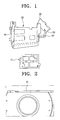
- Figure 1 illustrates an example of a conventional deck chassis assembly for a magnetic recording/reproducing apparatus having a moving deck.
- the conventional deck chassis assembly for a magnetic recording/reproducing apparatus comprises a base chassis 10, a housing chassis 20, a left bracket 30, a right bracket 40, a first link 50 and a second link 60.
- the base chassis 10 is fixed on a main body (not shown) of a magnetic recording/reproducing apparatus, and the moving deck (not shown) is mounted to an upper part of the base chassis 10.
- the housing chassis 20 is rotatable by a predetermined angle about one end such that the cassette loading means of the moving deck, mounted in the base chassis 10, may rotate with respect to a front top section of the base chassis 10. Thus, the front top section of the base chassis 10 is opened.
- a door (not shown) is provided on the outside of the housing chassis 20 and has a catch for preventing the housing chassis 20 from being opened.
- the left and right brackets 30, 40 support the housing chassis 20. Therefore, the housing chassis 20 is disposed above the base chassis 10 and may pivot by a predetermined angle with respect to the base chassis 10, using the first and the second links 50, 60.
- the upper ends of the left and the right brackets 30, 40 are rotatably connected to corresponding positions on the housing chassis 20. Lower parts of the left and the right brackets 30, 40 are fixed to the main body of the magnetic recording/reproducing apparatus.
- the first and second links 50, 60 are interposed between the left bracket 30 and the housing chassis 20.
- the housing chassis 20 may be opened to a predetermined angle with respect to the base chassis 10.
- the first and the second links 50, 60 are rotatably connected by a rivet hinge to each other at one end.
- the links 50, 60 are also rotatably connected to the housing chassis 20 and the left bracket 30 at the other end of each, respectively, by a rivet hinge.
- a locking bracket 70 is provided at the front of the base chassis 10 to engage with the catch of the door, connected to the housing chassis 20. Thus, the housing chassis 20 is prevented from being opened.
- An example of the locking bracket 70 is illustrated in Figure 2.
- the housing chassis 20 turns by a predetermined angle about the rivet hinges. Accordingly, the housing chassis 20 is opened.
- a sensor within the main body senses the housing chassis 20 opened, and therefore, the cassette loading means of the moving deck is ejected. As a result, the user can load or unload a cassette tape to or from the moving deck.
- the conventional deck chassis assembly for a magnetic recording/reproducing apparatus comprises at least seven parts, including: the base chassis 10, the housing chassis 20, the left and right brackets 30, 40, the first and second links 50, 60 and the locking bracket 70.
- the base chassis 10 a subassembly of the housing chassis 20 and the locking bracket 70 are separately connected to the main body of the magnetic recording/reproducing apparatus.
- a tape deck is characterised in that the housing chassis is pivotably coupled to the base chassis for movement between an open, tape-receiving position and a closed position.
- the base chassis includes a floor and side members, projecting substantially perpendicularly from opposite sides of said floor, and the housing chassis is hinged to the side members for said movement between its open, tape-receiving position and its closed position.
- a hinged link, coupling the base chassis and the housing chassis may be included and have a projection received in a slot in one of said side members and moves along the slot during said movement of the housing chassis.
- Sensing means may be included for detecting that the housing chassis in its open position.
- the sensing means may comprises a sensor, e.g. a switch or an optoelectronic device, mounted to the base chassis, and a tab on the housing chassis and positioned to be detected by the sensor when the housing chassis is in its open position.
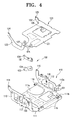
- a deck chassis assembly 100 for a magnetic recording/reproducing apparatus comprises a base chassis 110, mounted in the main body of the magnetic recording/reproducing apparatus, a housing chassis 120, rotatable through a predetermined angle to open and close a top portion of the base chassis 110, and a link member 130, interposed between the base chassis 110 and the housing chassis 120.
- the housing chassis 120 may be opened and closed through a predetermined angle with respect to the base chassis 110.
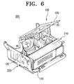
- a moving deck 210 ( Figure 6) is mounted at an upper portion of the base chassis 110 for loading and unloading of tape cassettes (not shown).
- the base chassis 110 has sidewalls 112, 113, integrally formed on opposite sides, to define a space for receiving the moving deck 210. Accordingly, the base chassis 110 has a substantially flattened U-shape.
- a motor receiving portion 111a of the moving deck 210 preferably for a capstan motor, is formed by processing the bottom 111 of the base chassis 110.
- the sidewalls 112, 113 of the base chassis 110 respectively have first hinge holes 114, 115 at upper ends thereof to rotatably connect a rivet hinge 103 with the housing chassis 120 (which will be described hereinbelow in detail).
- a second hinge hole 117 is formed on one sidewall 113 of the base chassis 110 to rotatably connect with the one end of the link member 130.
- the housing chassis 120 may easily turn about the link member 130 through a predetermined angle in an opening and closing manner.
- the bottom 111 of the base chassis 110 has a plurality of tap holes 111b for fixing the circuit board 220 ( Figure 6).
- the other sidewall 112 has a plurality of fixing holes 112a to fix the base chassis 110 to the main body of the magnetic recording/reproducing apparatus.
- a plurality of openings 101 may be formed on the bottom 111 and sidewalls 112 and 113 of the base chassis 110. This reduces the weight of the base chassis 110. The number of openings 101 is determined in accordance with the strength required of the base chassis 110.
- a locking part 119 may be provided at the front of the base chassis 110, that is, where the catch 302 ( Figure 7) of the door 300 ( Figure 7) is inserted when the base chassis 110 is mounted to the main body of the magnetic recording/reproducing apparatus.
- the housing chassis 120 is preferably formed as one body and has a substantially flattened U-shape.
- the housing chassis 120 has a width receivable in the base chassis 110.
- Sidewalls 122, 123 of the housing chassis 120 have respective third hinge holes 124, 125 at lower ends thereof for being rotatably connected with the base chassis 110 by rivet hinges 103.
- One sidewall 123 of the housing chassis 120 has a fourth hinge hole 127 formed for rotatable connection with the one end of the link member 130.
- the housing chassis 120 can easily turn about the link member 130 through a predetermined angle relative to the base chassis 110.
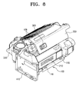
- the sidewalls 122, 123 of the housing chassis 120 may have various forms, to the extent that a bottom 121 of the housing chassis 120 maintains suitable strength to open and close the top of the base chassis 110. As shown in Figure 8, the bottom 121 of the housing chassis 120 includes a door connection hole 128 for connecting the door 300.
- a first guide slot 126 is formed on the other sidewall 122 of the housing chassis 120, opposite to the sidewall 123 connected to the link member 130.
- the first guide slot 126 guides and restricts the opening and closing movement of the housing chassis 120.
- the sidewall 112 of the base chassis 110 corresponds to the sidewall 122 of the base chassis 120, and is provided with a first guide pin 116 guided by the first guide slot 126.
- the first guide pin 116 may be formed by processing the rivet hinge 103.
- the link member 130 enables the housing chassis 120 to turn relative to the base chassis 110 by a predetermined angle in an opening and closing manner.
- the link member 130 may be structured in various manners.
- the link member 130 comprises a first link 131 and a second link 132.
- the first link hole 133 is rotatably connected by the rivet hinge 103 with the second hinge hole 117 formed on one sidewall 113 of the base chassis 110.
- the other end of the first link 131 is rotatably connected with one end of the second link 132 by the rivet hinge 103.
- a second link hole 134, formed on the other end of the second link 132, is rotatably connected by the rivet hinge 103 with the fourth hinge hole 127 of the sidewall 123 of the housing chassis 120. Accordingly, the first and the second links 131, 132 enable the housing chassis 120 to open and close the top of the base chassis 110 by a predetermined angle.
- a second guide slot 136 is formed at one sidewall 113 of the base chassis 110, where the fist link 131 is rotatably connected, and a second guide pin (not shown) is formed corresponding to the second guide slot 136. Consequently, the turning angle of the first link 131 is restricted, thereby smoothing the opening and closing operation of the housing chassis 120.
- a sensor 140 is mounted with the deck chassis assembly 100.
- the sensor 140 detects opening and closing of the housing chassis 120.
- a sensor mounting portion 141 is provided on one sidewall 112 of the base chassis 110 and a tab 142 is provided at the housing chassis 120 to operate the sensor 140.
- the sensor mounting portion 141 is formed outward on one sidewall 112 of the base chassis 110 and has the first guide pin 116.
- the tab 142 is formed on the corresponding sidewall 122 of the housing chassis 120 to operate the sensor 140, mounted in the sensor mounting portion 141.
- the sensor 140 is first connected to the circuit board 220 ( Figure 6) to control the moving deck 210 and to a test jig which supplies power to the circuit board 220 ( Figure 6).
- the operation of the moving deck 210 which moves in and out according to the opening and closing of the housing chassis 120, can be tested even before assembly of the magnetic recording/reproducing apparatus is complete.
- the base chassis 110 and the housing chassis 120 are rotatably connected to each other using the rivet hinge 103.
- the rivet hinge 103 connection is accomplished by aligning the first hinge holes 114, 115 of the base chassis 110 and the third hinge holes 124, 125 of the housing chassis 120.
- the rivet hinge 103 preferably of a shaft shape, is inserted in the first and third hinge holes. Both ends of the rivet hinge 103 are compressed by a riveting machine so that the rivet hinges 103 do not come out of the holes. Therefore, the housing chassis 120 and the base chassis 110 can smoothly turn about the rivet hinge 103.
- the hinge riveting is performed on the sidewalls 112, 113 of the base chassis 110 and the sidewalls 122, 123 of the housing chassis 120, so that the first guide pin 116 is inserted into the first guide slot 126.
- the first link hole 133 of the first link 131 is connected to the second hinge hole 117 of the base chassis 110 by the rivet hinge 103.
- the second link hole 134 is connected to the fourth hinge hole 127 of the housing chassis 120 by the rivet hinge 103. Therefore, the housing chassis 120 can turn relative to the base chassis 110 through a predetermined angle in an opening and closing manner.
- the first link 131 is connected to the base chassis 110 by the rivet hinge 103 after the second guide pin (not shown) has been inserted in the second guide slot 136.
- the base chassis 110, the housing chassis 120, the first link 131 and the second link 132 are rotatably connected by the rivet hinge 103 at five spots. Therefore, a user can open and close the housing chassis 120 relative to the base chassis 110 by a predetermined angle simply by pushing the front of the housing chassis 120. More specifically, as shown in Figure 6, when the user pushes upwardly on the front of the housing chassis 120, the housing chassis 120 is opened by a predetermined angle. As shown in Figure 5, when the user pushes downwardly on the front of the housing chassis 120, the housing chassis 120 closes the top of the base chassis 110.
- the moving deck 210 and the circuit board 220 controlling the moving deck 220 are mounted to the above-assembled deck chassis assembly 100, thereby completing a deck assembly 200.
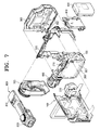
- camcorder having a still camera lens as well as a camcorder lens will be described as an example of the magnetic recording/reproducing apparatus which employs the deck chassis described above.
- the camcorder comprises the deck assembly 200, including the moving deck 210, in which tape cassettes (not shown) can be loaded and unloaded. Additionally, door 300 is connected to the housing chassis 120 and left casing 310 serves as the frame of the door A battery mounting portion 410 is formed at the rear of the left casing 310 for receiving a battery 400.
- a right casing 500 constitutes the main body of the dual camcorder together with the left casing 310 and comprises a subassembly with a camera unit which includes a still camera lens 510.
- a camcorder lens unit 600 is fixed at the front of the deck assembly 200.
- the camcorder also includes a front casing 700, for fixing the still camera lens 510 and the camcorder lens unit 600, and an upper casing 800, including a flash 810 and a viewfinder 820.
- the deck assembly 200 comprises the deck chassis assembly 100 described above.
- the moving deck 210 is mounted to the deck chassis assembly 100 and the circuit board 220.
- the circuit board 220 comprises a moving image processing circuit for recording moving images as well as a circuit for controlling the moving deck 210.
- the left casing 310 is fixed to the deck assembly 200 and the door 300 is mounted to the door connection hole 128 of the housing chassis 120, as shown in Figure 8. If the door 300 is pressed, in this state, the catch 302 ( Figure 7) formed at an inside of a lower portion of the door 300 is engaged with the locking part 119 of the deck chassis assembly 100.
- a catch releasing button 303 provided at an outside of the lower part of the door 300, is pushed in a sliding manner so that the catch 302 escapes from the locking part 119.
- the tab 142 of the housing chassis 120 is disposed on a front of the sensor 140. Therefore, the sensor 140 senses the door 300 opened and transmits a signal to the circuit board 220. Accordingly, the circuit board 220 controls the moving deck 210 so that the cassette loading means of the moving deck 210 protrudes with respect to the base chassis 110.
- the cassette loading means of the moving deck 210 protrudes, the user can load or unload the tape cassette to or from the moving deck 210.
- the operation of the moving deck 210 including loading the tape cassette toward a head drum and controlling running of a magnetic tape, will not be described in detail since it is the same as in conventional moving decks.
- the deck assembly 200, the left casing 310 and the door 300 are sub-assembled by mounting the right casing 500, the camcorder lens unit 600, the front casing 700 and the upper casing 800 in order, and assembly of the camcorder is complete.
- the deck chassis assembly for a magnetic recording/reproducing apparatus may save costs for material handling, packaging and management by reducing the number of component parts.
- the conventional deck chassis assembly comprises seven parts
- the deck chassis assembly 200 according to the present invention may comprise only the following four main parts: the base chassis, the housing chassis, the first link and the second link.
- the deck chassis assembly 200 is mounted to the main body of the magnetic recording/reproducing apparatus, as one independent module. Therefore, assembly time is minimized. Moreover, assembly thereof is simplified.
- an operation test for the moving deck 210 may be performed using a test jig when the deck chassis assembly 200 and the moving deck 210 are sub-assembled.
- a test jig when the deck chassis assembly 200 and the moving deck 210 are sub-assembled.
Landscapes
- Casings For Electric Apparatus (AREA)
Applications Claiming Priority (2)
| Application Number | Priority Date | Filing Date | Title |
|---|---|---|---|
| KR2004016028 | 2004-03-10 | ||
| KR1020040016028A KR20050090783A (ko) | 2004-03-10 | 2004-03-10 | 자기 기록/재생장치의 데크 샤시구조 |
Publications (2)
| Publication Number | Publication Date |
|---|---|
| EP1575052A2 true EP1575052A2 (de) | 2005-09-14 |
| EP1575052A3 EP1575052A3 (de) | 2008-04-09 |
Family
ID=34825195
Family Applications (1)
| Application Number | Title | Priority Date | Filing Date |
|---|---|---|---|
| EP05101468A Withdrawn EP1575052A3 (de) | 2004-03-10 | 2005-02-25 | Bandlaufwerk |
Country Status (5)
| Country | Link |
|---|---|
| US (1) | US20050201008A1 (de) |
| EP (1) | EP1575052A3 (de) |
| JP (1) | JP2005259338A (de) |
| KR (1) | KR20050090783A (de) |
| CN (1) | CN1667728A (de) |
Families Citing this family (2)
| Publication number | Priority date | Publication date | Assignee | Title |
|---|---|---|---|---|
| US8631903B2 (en) * | 2005-07-21 | 2014-01-21 | Werner Co. | Pump jack pole brace latch and method |
| US11674345B2 (en) * | 2016-04-19 | 2023-06-13 | Commscope, Inc. Of North Carolina | Door assembly for a telecommunications chassis with a combination hinge structure |
Family Cites Families (13)
| Publication number | Priority date | Publication date | Assignee | Title |
|---|---|---|---|---|
| JPH087910B2 (ja) * | 1986-04-11 | 1996-01-29 | キヤノン株式会社 | 記録再生装置 |
| US4949203A (en) * | 1987-03-11 | 1990-08-14 | Pioneer Electronic Corporation | Tape recorder having an improved cassette mounting device |
| JPH0519867Y2 (de) * | 1987-12-15 | 1993-05-25 | ||
| CA1332757C (en) * | 1988-11-09 | 1994-10-25 | Takao Kumagai | Loading system for tape cassette in recording and/or reproducing apparatus |
| JP2644888B2 (ja) * | 1989-04-24 | 1997-08-25 | 株式会社日立製作所 | カセット装着装置 |
| TW242732B (en) * | 1993-06-29 | 1995-03-11 | Victor Company Of Japan | Digital chrominance signal processing circuit |
| KR0120540B1 (ko) * | 1993-07-26 | 1997-10-27 | 김광호 | 테이프 레코더의 도어장치 |
| CA2130011C (en) * | 1993-08-24 | 2004-03-30 | Masayoshi Morikawa | Cassette eject mechanism, battery loading mechanism and mechanical chassis supporting mechanism |
| JPH08263904A (ja) * | 1995-03-24 | 1996-10-11 | Aiwa Co Ltd | 記録媒体の出し入れ装置 |
| JPH10261879A (ja) * | 1996-12-09 | 1998-09-29 | Sharp Corp | 扉の開閉機構 |
| JPH11224481A (ja) * | 1998-02-04 | 1999-08-17 | Sony Corp | メディア用ホルダの取付構造 |
| US6392837B1 (en) * | 1999-05-28 | 2002-05-21 | Seagate Removable Storage Solutions Llc | Technique for opening door of a tape cartridge to access the tape leader pin |
| US6621657B1 (en) * | 2001-01-08 | 2003-09-16 | Seagate Removable Storage Solutions Llc | Tape drive cartridge latching mechanism |
-
2004
- 2004-03-10 KR KR1020040016028A patent/KR20050090783A/ko not_active Withdrawn
-
2005
- 2005-02-09 US US11/052,858 patent/US20050201008A1/en not_active Abandoned
- 2005-02-25 EP EP05101468A patent/EP1575052A3/de not_active Withdrawn
- 2005-03-02 CN CNA2005100529389A patent/CN1667728A/zh active Pending
- 2005-03-07 JP JP2005063133A patent/JP2005259338A/ja active Pending
Also Published As
| Publication number | Publication date |
|---|---|
| CN1667728A (zh) | 2005-09-14 |
| US20050201008A1 (en) | 2005-09-15 |
| KR20050090783A (ko) | 2005-09-14 |
| EP1575052A3 (de) | 2008-04-09 |
| JP2005259338A (ja) | 2005-09-22 |
Similar Documents
| Publication | Publication Date | Title |
|---|---|---|
| KR100336929B1 (ko) | 기록매체를수납하는카트리지용기록재생장치 | |
| CA2130011C (en) | Cassette eject mechanism, battery loading mechanism and mechanical chassis supporting mechanism | |
| KR940005799B1 (ko) | 소형 수납용 포울딩 캠코더 | |
| US5541809A (en) | Electronic equipments chassis made from bent sheet metal | |
| US5825583A (en) | Magnetic recording and reproducing apparatus deck mechanism with a slide base and a power transmission mechanism respectively disposed on opposite side surfaces of a fixed base plate | |
| US4800449A (en) | DAT recorder with automatic cassette movement | |
| EP1575052A2 (de) | Bandlaufwerk | |
| US5523907A (en) | Door mechanism for a tape recorder | |
| EP0887798B1 (de) | Magnetaufzeichnungs- und Wiedergabegerät mit Tablettladung | |
| KR20000053576A (ko) | 고체상태 기억소자를 사용하는 기록매체에 장착하기 위한전자기기 | |
| US7055157B2 (en) | Loading motor control device of optical disc player | |
| US6754039B2 (en) | Cassette loading apparatus | |
| US5687041A (en) | Cassette lid opening apparatus for top-loading camcorder | |
| KR100465166B1 (ko) | 테이프 레코더의 테이프 카세트 하우징 록킹장치 | |
| KR100465223B1 (ko) | 자기 기록/재생장치의 릴브레이크 조립체 | |
| US4788616A (en) | Tape cassette loading and unloading apparatus comprising holder moving means and movement synchronizing mechanism | |
| US5497278A (en) | Cassette mounting device having cassette removal facility additional to customary insertion/ejection aperture part | |
| EP1575276A1 (de) | Kamerarekorder | |
| US7032852B2 (en) | Tape loading device for a tape recorder | |
| US6962303B2 (en) | Recording tape cartridge | |
| EP1622439A2 (de) | Vorrichtung zum Öffnen und Schliessen einer Tür, elektronisches Gerät mit dieser Vorrichtung | |
| JP3154203B2 (ja) | テープ駆動装置 | |
| JP3318799B2 (ja) | カセット着脱装置 | |
| JPS63261594A (ja) | テ−プレコ−ダ | |
| JP2002133842A (ja) | ディスクプレーヤーのパネル装置及びディスクプレーヤー一体型テレビジョン受像装置 |
Legal Events
| Date | Code | Title | Description |
|---|---|---|---|
| PUAI | Public reference made under article 153(3) epc to a published international application that has entered the european phase |
Free format text: ORIGINAL CODE: 0009012 |
|
| AK | Designated contracting states |
Kind code of ref document: A2 Designated state(s): AT BE BG CH CY CZ DE DK EE ES FI FR GB GR HU IE IS IT LI LT LU MC NL PL PT RO SE SI SK TR |
|
| AX | Request for extension of the european patent |
Extension state: AL BA HR LV MK YU |
|
| PUAL | Search report despatched |
Free format text: ORIGINAL CODE: 0009013 |
|
| AK | Designated contracting states |
Kind code of ref document: A3 Designated state(s): AT BE BG CH CY CZ DE DK EE ES FI FR GB GR HU IE IS IT LI LT LU MC NL PL PT RO SE SI SK TR |
|
| AX | Request for extension of the european patent |
Extension state: AL BA HR LV MK YU |
|
| 17P | Request for examination filed |
Effective date: 20080618 |
|
| 17Q | First examination report despatched |
Effective date: 20080725 |
|
| AKX | Designation fees paid |
Designated state(s): DE FR GB IT NL |
|
| STAA | Information on the status of an ep patent application or granted ep patent |
Free format text: STATUS: THE APPLICATION IS DEEMED TO BE WITHDRAWN |
|
| 18D | Application deemed to be withdrawn |
Effective date: 20081205 |