EP1574771A2 - Ventil für den Einsatz in Streckblasmaschinen - Google Patents
Ventil für den Einsatz in Streckblasmaschinen Download PDFInfo
- Publication number
- EP1574771A2 EP1574771A2 EP05002885A EP05002885A EP1574771A2 EP 1574771 A2 EP1574771 A2 EP 1574771A2 EP 05002885 A EP05002885 A EP 05002885A EP 05002885 A EP05002885 A EP 05002885A EP 1574771 A2 EP1574771 A2 EP 1574771A2
- Authority
- EP
- European Patent Office
- Prior art keywords
- valve
- control piston
- face
- control
- line
- Prior art date
- Legal status (The legal status is an assumption and is not a legal conclusion. Google has not performed a legal analysis and makes no representation as to the accuracy of the status listed.)
- Withdrawn
Links
Images


Classifications
-
- F—MECHANICAL ENGINEERING; LIGHTING; HEATING; WEAPONS; BLASTING
- F16—ENGINEERING ELEMENTS AND UNITS; GENERAL MEASURES FOR PRODUCING AND MAINTAINING EFFECTIVE FUNCTIONING OF MACHINES OR INSTALLATIONS; THERMAL INSULATION IN GENERAL
- F16K—VALVES; TAPS; COCKS; ACTUATING-FLOATS; DEVICES FOR VENTING OR AERATING
- F16K31/00—Actuating devices; Operating means; Releasing devices
- F16K31/12—Actuating devices; Operating means; Releasing devices actuated by fluid
- F16K31/122—Actuating devices; Operating means; Releasing devices actuated by fluid the fluid acting on a piston
- F16K31/1226—Actuating devices; Operating means; Releasing devices actuated by fluid the fluid acting on a piston the fluid circulating through the piston
-
- F—MECHANICAL ENGINEERING; LIGHTING; HEATING; WEAPONS; BLASTING
- F16—ENGINEERING ELEMENTS AND UNITS; GENERAL MEASURES FOR PRODUCING AND MAINTAINING EFFECTIVE FUNCTIONING OF MACHINES OR INSTALLATIONS; THERMAL INSULATION IN GENERAL
- F16K—VALVES; TAPS; COCKS; ACTUATING-FLOATS; DEVICES FOR VENTING OR AERATING
- F16K39/00—Devices for relieving the pressure on the sealing faces
- F16K39/02—Devices for relieving the pressure on the sealing faces for lift valves
- F16K39/022—Devices for relieving the pressure on the sealing faces for lift valves using balancing surfaces
-
- B—PERFORMING OPERATIONS; TRANSPORTING
- B29—WORKING OF PLASTICS; WORKING OF SUBSTANCES IN A PLASTIC STATE IN GENERAL
- B29C—SHAPING OR JOINING OF PLASTICS; SHAPING OF MATERIAL IN A PLASTIC STATE, NOT OTHERWISE PROVIDED FOR; AFTER-TREATMENT OF THE SHAPED PRODUCTS, e.g. REPAIRING
- B29C2949/00—Indexing scheme relating to blow-moulding
- B29C2949/07—Preforms or parisons characterised by their configuration
- B29C2949/0715—Preforms or parisons characterised by their configuration the preform having one end closed
-
- B—PERFORMING OPERATIONS; TRANSPORTING
- B29—WORKING OF PLASTICS; WORKING OF SUBSTANCES IN A PLASTIC STATE IN GENERAL
- B29C—SHAPING OR JOINING OF PLASTICS; SHAPING OF MATERIAL IN A PLASTIC STATE, NOT OTHERWISE PROVIDED FOR; AFTER-TREATMENT OF THE SHAPED PRODUCTS, e.g. REPAIRING
- B29C49/00—Blow-moulding, i.e. blowing a preform or parison to a desired shape within a mould; Apparatus therefor
- B29C49/02—Combined blow-moulding and manufacture of the preform or the parison
- B29C49/06—Injection blow-moulding
-
- B—PERFORMING OPERATIONS; TRANSPORTING
- B29—WORKING OF PLASTICS; WORKING OF SUBSTANCES IN A PLASTIC STATE IN GENERAL
- B29C—SHAPING OR JOINING OF PLASTICS; SHAPING OF MATERIAL IN A PLASTIC STATE, NOT OTHERWISE PROVIDED FOR; AFTER-TREATMENT OF THE SHAPED PRODUCTS, e.g. REPAIRING
- B29C49/00—Blow-moulding, i.e. blowing a preform or parison to a desired shape within a mould; Apparatus therefor
- B29C49/42—Component parts, details or accessories; Auxiliary operations
- B29C49/4289—Valve constructions or configurations, e.g. arranged to reduce blowing fluid consumption
-
- B—PERFORMING OPERATIONS; TRANSPORTING
- B29—WORKING OF PLASTICS; WORKING OF SUBSTANCES IN A PLASTIC STATE IN GENERAL
- B29K—INDEXING SCHEME ASSOCIATED WITH SUBCLASSES B29B, B29C OR B29D, RELATING TO MOULDING MATERIALS OR TO MATERIALS FOR MOULDS, REINFORCEMENTS, FILLERS OR PREFORMED PARTS, e.g. INSERTS
- B29K2067/00—Use of polyesters or derivatives thereof, as moulding material
-
- B—PERFORMING OPERATIONS; TRANSPORTING
- B29—WORKING OF PLASTICS; WORKING OF SUBSTANCES IN A PLASTIC STATE IN GENERAL
- B29L—INDEXING SCHEME ASSOCIATED WITH SUBCLASS B29C, RELATING TO PARTICULAR ARTICLES
- B29L2031/00—Other particular articles
- B29L2031/712—Containers; Packaging elements or accessories, Packages
- B29L2031/7158—Bottles
Definitions
- the present invention relates to a valve according to the Preamble of claim 1.
- the object of the present invention was a Valve to find which stretch blow molder with large Air volumes at a high pressure level with high Operational safety supplied.
- a first end face of the control piston directed against the feed pressure input line and closes these in a closed position opposite the Supply pressure output line from.
- a Connecting channel between this first end face and the formed opposite the second end face wherein in the closed position of the control piston, the effective area the second end face is greater than the effective area of the first end face.
- the big advantage of this arrangement is that the Feed pressure, which is for blowing the preforms is used, even for the closing of the valve is used.
- the pilot or pilot pressure which a has significantly lower pressure level, is advantageous used for opening the valve. If now the Control pressure is absent, for example by a Line break in the pressure supply, this is the valve stay closed and it does not come to a unwanted feed pressure supply to the processing machine.
- control piston is a circular cylindrical Body trained. Due to the circular symmetrical shape can an optimal valve effect can be achieved.
- a single, in the longitudinal axis of the Control piston arranged connecting channel formed, which is preferably designed as a cylindrical bore is. This will be a reliable connection of the two End faces of the control piston with the feed pressure line achieved, which is also easy and inexpensive in the Production is.
- control surface is between the two End faces of the control piston arranged, preferably as substantially perpendicular to the longitudinal axis of the control piston trained ring surface.
- This will be a very compact Construction of the valve achieved.
- the arrangement of Sealing surfaces between the feed pressure resp. the Control pressure having chambers can thus optimized become.
- the first end face of the control piston an axially protruding, closed collar, preferably in ring form, on.
- This collar is Preferably designed such that in closed Condition with the feed pressure input line in Compound effective area of the face is smaller, as in the open state of the control piston. This is when Opening the valve the effective area, which with the high Supply pressure is connected, enlarged and thus the Valve resp. the spool quickly into the Opening position brought.
- the triggering of Opening process is done solely by building Control pressure and is thus virtually independent of Feed pressure.
- the valve assembly is both for the supply of air for the pre - blowing, which in usually at a pressure level of 6 to 20 bar, as well as for final blowing at a pressure level of 35 up to 40 bar.
- control piston in the closing direction supported by a spring element, preferably by means of a compression spring.
- a spring element preferably by means of a compression spring.
- valve according to the invention in stretch blow molding machines both for pre-blowing as well as for pre-blowing PET bottles claimed.
- This can be a safe supply the stretch blow molders with compressed air on the desired Pressure level can be ensured with a single valve.
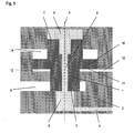
- Figure 1 shows schematically the view of the longitudinal section by a valve constructed according to the invention in the closed position.
- the control piston 1 is in Valve body 2 along its axis A longitudinally displaceable arranged. In the illustrated, closed position closes the lower end face 3 of the control piston 1 the Feed pressure input line 4 of the Supply pressure output line 5 sealing off.
- the feed pressure output line 5 is in communication with the production machine, for example for PET bottles (not shown).
- the feed pressure input line 4 opens into a lower Valve chamber 6, which with the lower end face 3 of the Control piston 1 is in communication.
- the upper end face 7 of the control piston 1 opens into an upper, closed Valve chamber 8.
- a connecting line 9 formed, which thus a connection between the lower valve chamber 6 and the upper valve chamber 8 creates.
- the corresponding area ratios of the lower and upper faces 3 resp. 7 can be advantageous by a cylindrical version of the control piston 1 achieved be, with the diameter of the control piston in the range the upper end face 7 is larger than the diameter in Area of the lower end face 3 resp. of the diameter of the lower valve chamber 6.
- the control piston 1 now has a further radially Outer projecting ring 10, which radially opposite the housing 2 is sealed.
- the lower ring surface is used as a control surface 11 and is located in a control room 12, which is in communication with the control pressure line 13.
- the upper ring surface faces a further valve space 14, which is open and thus with the environment in Compound stands, i. Has ambient pressure.
- control surface 11 is larger for this purpose chosen as the difference between the upper and lower End face 7 resp. 3 of the control piston 1.
- This suffices for the opening of the valve is a smaller control pressure than the valve in the feed pressure supply 4 prevailing feed pressure. For example, it can with a control pressure of 6 bar the valve is opened with a feed pressure of 40 bar become.
- FIG. 3 is yet another embodiment of a Valve according to the invention also schematically in Longitudinal section shown.
- the lower end face 3 of the control piston 1 a down projecting, circularly closed collar 15.
- the collar is not on the edge of the control piston. 1 is arranged, but is offset radially inward, at the moment of opening the valve, the effective area of the lower end face 3 of the control piston 1 increases and so that the opening effect by reducing the resulting closing force by the feed pressure favorably supported. This is especially a fast response time resp. Opening time of the valve supported, which is virtually independent of the amount of Feed pressure is.
- the valve is suitable for use in both medium pressure range of about 6 to 20 bar, as well as in high pressure range up to 40 bar.
- For use in Stretch blow moulders can thus use the valve in one uniform size both for the pre-blowing as well be used for the final blow.
- a Compression spring 16 is arranged, which the control piston 1 in the closed starting position of Figure 1 expresses. This will be advantageous a defined ground state, namely the closed position, the valve reached, even if the Supply pressure supply line 4 not with a feed pressure is charged.
Landscapes
- Engineering & Computer Science (AREA)
- General Engineering & Computer Science (AREA)
- Mechanical Engineering (AREA)
- Blow-Moulding Or Thermoforming Of Plastics Or The Like (AREA)
Abstract
Description
Claims (7)
- Ventil für den Einsatz in Streckblasmaschinen für die Fertigung von Hohlkörpern aus Kunststoff, mit einem axial im Ventilgehäuse (2) verschiebbar angeordneten Steuerkolben (1), einer Speisedruckeingangsleitung (4), einer Speisedruckausgangsleitung (5) und einer Steuerdruckleitung (13), dadurch gekennzeichnet, dass eine erste Stirnfläche (3) des Steuerkolbens (1) mit der Speisedruckeingangsleitung (4) in Verbindung steht und diese in geschlossener Stellung des Ventils gegenüber der Speisedruckausgangsleitung (5) äbschliesst und dass weiter mindestens ein Verbindungskanal (9) zwischen dieser ersten Stirnfläche (3) und der gegenüberliegenden zweiten Stirnfläche (7) ausgebildet ist, wobei in geschlossener Stellung des Steuerkolbens (1) die Wirkfläche der zweiten Stirnfläche (7) grösser ist als die Wirkfläche der ersten Stirnfläche (3) und dass der Steuerkolben (1) weiter eine mit der Steuerdruckleitung (13) kommunizierende und gegenüber der Speisedruckeingangsleitung (4) getrennte Steuerfläche (11) aufweist.
- Ventil nach Anspruch 1, dadurch gekennzeichnet, dass der Steuerkolben (1) als kreiszylindrischer Körper ausgebildet ist.
- Ventil nach Anspruch 1 oder 2, dadurch gekennzeichnet, dass ein einziger, in der Längsachse des Steuerkolbens (1) angeordneter Verbindungskanal (9) ausgebildet ist, vorzugsweise als zylindrische Bohrung ausgeführt ist.
- Ventil nach einem der Ansprüche 1 bis 3, dadurch gekennzeichnet, dass die Steuerfläche (11) zwischen den beiden Stirnflächen (3;7) des Steuerkolbens (1) angeordnet ist, vorzugsweise als im Wesentlichen senkrecht zur Längsachse (A) des Steuerkolbens (1) ausgebildete Ringfläche (11).
- Ventil nach einem der Ansprüche 1 bis 4, dadurch gekennzeichnet, dass die erste Stirnfläche (3) des Steuerkolbens (1) einen axial vorstehenden, geschlossenen Kragen (15), vorzugsweise in Ringform, aufweist, vorzugsweise derart, dass in geschlossenem Zustand des Ventils die mit der Speisedruckeingangsleitung (4) in Verbindung stehende Wirkfläche der Stirnfläche (3) kleiner ist, als in offenem Zustand des Ventils.
- Ventil nach einem der Ansprüche 1 bis 5, dadurch gekennzeichnet, dass der Steuerkolben (1) in Schliessrichtung mittels eines Federelementes (16) abgestützt ist, vorzugsweise einer Druckfeder.
- Verwendung eines Ventils nach einem der Ansprüche 1 bis 6 in Streckblasmaschinen sowohl für das Vorblasen wie auch für das Fertigblasen von PET-Flaschen.
Applications Claiming Priority (2)
| Application Number | Priority Date | Filing Date | Title |
|---|---|---|---|
| CH3862004 | 2004-03-09 | ||
| CH3862004 | 2004-03-09 |
Publications (2)
| Publication Number | Publication Date |
|---|---|
| EP1574771A2 true EP1574771A2 (de) | 2005-09-14 |
| EP1574771A3 EP1574771A3 (de) | 2006-01-18 |
Family
ID=34812830
Family Applications (1)
| Application Number | Title | Priority Date | Filing Date |
|---|---|---|---|
| EP05002885A Withdrawn EP1574771A3 (de) | 2004-03-09 | 2005-02-11 | Ventil für den Einsatz in Streckblasmaschinen |
Country Status (1)
| Country | Link |
|---|---|
| EP (1) | EP1574771A3 (de) |
Cited By (15)
| Publication number | Priority date | Publication date | Assignee | Title |
|---|---|---|---|---|
| WO2008122311A1 (de) * | 2007-04-05 | 2008-10-16 | Eugen Seitz Ag | Luftgesteuertes ventil |
| WO2009010097A1 (de) * | 2007-07-17 | 2009-01-22 | Eugen Seitz Ag | Luftgesteuertes ventil |
| DE102008015776B3 (de) * | 2008-03-26 | 2009-07-23 | Festo Ag & Co. Kg | Ventileinheit und damit ausgestattete Streckblasvorrichtung |
| ITMI20101222A1 (it) * | 2010-07-02 | 2012-01-03 | Smi Spa | Dispositivo di regolazione della pressione in macchine stirosoffiatrici |
| EP2557344A1 (de) * | 2011-08-12 | 2013-02-13 | Mark IV, LLC | Gegenvorgespanntes Ventil und Aktoranordnung |
| CN102927350A (zh) * | 2011-08-12 | 2013-02-13 | 马克四世有限责任公司 | 反偏压阀和致动器组件 |
| CN101631663B (zh) * | 2006-10-17 | 2013-05-01 | 诺格伦有限责任公司 | 环形阀活塞及其在吹塑机中的使用 |
| WO2016012240A1 (de) * | 2014-07-22 | 2016-01-28 | Robert Bosch Gmbh | Hydraulisches einbauventil und hydraulische steueranordnung |
| WO2017092772A1 (en) * | 2015-12-04 | 2017-06-08 | Müller Gas Equipment A/S | Counter-biased valve actuator |
| FR3056670A1 (fr) * | 2016-09-27 | 2018-03-30 | Vianney Rabhi | Vanne tubulaire a commande hydraulique |
| EP3492787A1 (de) | 2017-11-29 | 2019-06-05 | Eugen Seitz AG | Ventileinheit |
| EP4082751A1 (de) | 2021-04-29 | 2022-11-02 | Eugen Seitz AG | Verfahren zum betreiben einer ventileinheit und ventileinheit |
| EP4293260A1 (de) | 2022-06-17 | 2023-12-20 | Eugen Seitz AG | Ventil |
| EP4293259A1 (de) | 2022-06-14 | 2023-12-20 | Eugen Seitz AG | Ventil |
| DE102023101697A1 (de) * | 2023-01-24 | 2024-07-25 | Zf Cv Systems Europe Bv | Wechselventil mit pneumatischer Vorzugsstellung |
Family Cites Families (3)
| Publication number | Priority date | Publication date | Assignee | Title |
|---|---|---|---|---|
| DE1142938B (de) * | 1960-10-21 | 1963-01-31 | Continental Elektro Ind Ag | Pneumatisches Schnellschaltventil fuer Hochspannungs-Druckluftschalter |
| US6276125B1 (en) * | 1998-12-17 | 2001-08-21 | Alliedsignal, Inc. | Pressure balanced poppet valve |
| DE10257718B4 (de) * | 2002-12-11 | 2005-11-24 | Hydac System Gmbh | Feuerlöschanlage |
-
2005
- 2005-02-11 EP EP05002885A patent/EP1574771A3/de not_active Withdrawn
Cited By (29)
| Publication number | Priority date | Publication date | Assignee | Title |
|---|---|---|---|---|
| CN101631663B (zh) * | 2006-10-17 | 2013-05-01 | 诺格伦有限责任公司 | 环形阀活塞及其在吹塑机中的使用 |
| CN101663524B (zh) * | 2007-04-05 | 2012-07-04 | 欧根赛驰股份公司 | 空气控制阀 |
| WO2008122311A1 (de) * | 2007-04-05 | 2008-10-16 | Eugen Seitz Ag | Luftgesteuertes ventil |
| WO2009010097A1 (de) * | 2007-07-17 | 2009-01-22 | Eugen Seitz Ag | Luftgesteuertes ventil |
| EP2105641A2 (de) | 2008-03-26 | 2009-09-30 | Festo AG & Co. KG | Ventileinheit und damit ausgestattete Streckblasvorrichtung |
| DE102008015776B3 (de) * | 2008-03-26 | 2009-07-23 | Festo Ag & Co. Kg | Ventileinheit und damit ausgestattete Streckblasvorrichtung |
| ITMI20101222A1 (it) * | 2010-07-02 | 2012-01-03 | Smi Spa | Dispositivo di regolazione della pressione in macchine stirosoffiatrici |
| EP2402143A1 (de) * | 2010-07-02 | 2012-01-04 | SMI S.p.A. | Druckeinstellvorrichtung in Streckblasmaschinen, Vorrichtung und Verfahren |
| US8657598B2 (en) | 2010-07-02 | 2014-02-25 | Smi S.P.A. | Pressure adjustment device in stretch blow moulding machines |
| CN102927350A (zh) * | 2011-08-12 | 2013-02-13 | 马克四世有限责任公司 | 反偏压阀和致动器组件 |
| EP2557344A1 (de) * | 2011-08-12 | 2013-02-13 | Mark IV, LLC | Gegenvorgespanntes Ventil und Aktoranordnung |
| WO2016012240A1 (de) * | 2014-07-22 | 2016-01-28 | Robert Bosch Gmbh | Hydraulisches einbauventil und hydraulische steueranordnung |
| WO2017092772A1 (en) * | 2015-12-04 | 2017-06-08 | Müller Gas Equipment A/S | Counter-biased valve actuator |
| DK179057B1 (da) * | 2015-12-04 | 2017-09-25 | Müller Gas Equipment As | Balanceret reguleringsventil |
| US10724650B2 (en) | 2015-12-04 | 2020-07-28 | Müller Gas Equipment A/S | Balanced regulating valve |
| FR3056670A1 (fr) * | 2016-09-27 | 2018-03-30 | Vianney Rabhi | Vanne tubulaire a commande hydraulique |
| WO2019105783A1 (de) | 2017-11-29 | 2019-06-06 | Eugen Seitz Ag | Ventileinheit |
| EP3492787A1 (de) | 2017-11-29 | 2019-06-05 | Eugen Seitz AG | Ventileinheit |
| JP2021504656A (ja) * | 2017-11-29 | 2021-02-15 | オイゲン ザイツ アーゲー | 弁ユニット |
| EP4006390A1 (de) | 2017-11-29 | 2022-06-01 | Eugen Seitz AG | Ventileinheit |
| US12208561B2 (en) | 2017-11-29 | 2025-01-28 | Eugen Seitz Ag | Valve unit |
| US11712834B2 (en) | 2017-11-29 | 2023-08-01 | Eugen Seitz Ag | Valve unit |
| US12042975B2 (en) | 2021-04-29 | 2024-07-23 | Eugen Seitz Ag | Method for operating a valve unit and valve unit |
| EP4082751A1 (de) | 2021-04-29 | 2022-11-02 | Eugen Seitz AG | Verfahren zum betreiben einer ventileinheit und ventileinheit |
| EP4293259A1 (de) | 2022-06-14 | 2023-12-20 | Eugen Seitz AG | Ventil |
| US12435795B2 (en) | 2022-06-14 | 2025-10-07 | Eugen Seitz Ag | Valve |
| WO2023242350A1 (de) | 2022-06-17 | 2023-12-21 | Eugen Seitz Ag | Ventileinheit |
| EP4293260A1 (de) | 2022-06-17 | 2023-12-20 | Eugen Seitz AG | Ventil |
| DE102023101697A1 (de) * | 2023-01-24 | 2024-07-25 | Zf Cv Systems Europe Bv | Wechselventil mit pneumatischer Vorzugsstellung |
Also Published As
| Publication number | Publication date |
|---|---|
| EP1574771A3 (de) | 2006-01-18 |
Similar Documents
| Publication | Publication Date | Title |
|---|---|---|
| EP1574771A2 (de) | Ventil für den Einsatz in Streckblasmaschinen | |
| EP2142830B1 (de) | Luftgesteuertes ventil | |
| EP2911964B1 (de) | Ventil für unterdruckhandhabungs- oder unterdruckspannvorrichtung, sowie unterdruckhandhabungseinrichtung | |
| DE112016004954T5 (de) | Fluidsteuerventil | |
| EP1435028B1 (de) | Druckregelventil, insbesondere proportional-druckregelventil | |
| EP2167303B1 (de) | Ventileinrichtung für hohlkörperblasmaschinen und verfahren zum einblasen von drukluft in ein blasvolumen | |
| WO2011012366A1 (de) | Druckregelventil | |
| EP2105641A2 (de) | Ventileinheit und damit ausgestattete Streckblasvorrichtung | |
| EP1913241A1 (de) | Pneumatisches druckregelventil | |
| DE102014017801A1 (de) | Druckbegrenzungsventil | |
| EP1970190A2 (de) | Vorrichtung zum Behandeln von Behältnissen | |
| EP2240310B1 (de) | Vorrichtung zum einblasen von druckluft in eine blasform | |
| WO2018177753A1 (de) | Kraftstoff-hochdruckpumpe | |
| DE102014000814B4 (de) | Ventileinheit | |
| WO2009010097A1 (de) | Luftgesteuertes ventil | |
| EP3238637B1 (de) | Druckgasbetriebenes instrument, insbesondere chirurgisches instrument | |
| EP2597337A2 (de) | Hydraulikanordnung | |
| EP2347887A1 (de) | Ventileinrichtung | |
| EP2496867A1 (de) | Ventilanordnung | |
| DE102006016318A1 (de) | Schraubenverdichter mit Entlastungsventil | |
| EP4293259A1 (de) | Ventil | |
| EP0866394B1 (de) | Governor für Druckluftbeschaffungsanlagen von Fahrzeugen | |
| EP4011660A1 (de) | Ventil | |
| EP4416394B1 (de) | Zylinderentgasungseinheit und arbeitszylinder | |
| DE102005057489A1 (de) | Hydraulisches Ventil |
Legal Events
| Date | Code | Title | Description |
|---|---|---|---|
| PUAI | Public reference made under article 153(3) epc to a published international application that has entered the european phase |
Free format text: ORIGINAL CODE: 0009012 |
|
| AK | Designated contracting states |
Kind code of ref document: A2 Designated state(s): AT BE BG CH CY CZ DE DK EE ES FI FR GB GR HU IE IS IT LI LT LU MC NL PL PT RO SE SI SK TR |
|
| AX | Request for extension of the european patent |
Extension state: AL BA HR LV MK YU |
|
| PUAL | Search report despatched |
Free format text: ORIGINAL CODE: 0009013 |
|
| AK | Designated contracting states |
Kind code of ref document: A3 Designated state(s): AT BE BG CH CY CZ DE DK EE ES FI FR GB GR HU IE IS IT LI LT LU MC NL PL PT RO SE SI SK TR |
|
| AX | Request for extension of the european patent |
Extension state: AL BA HR LV MK YU |
|
| 17P | Request for examination filed |
Effective date: 20060704 |
|
| AKX | Designation fees paid |
Designated state(s): AT BE BG CH CY CZ DE DK EE ES FI FR GB GR HU IE IS IT LI LT LU MC NL PL PT RO SE SI SK TR |
|
| 17Q | First examination report despatched |
Effective date: 20060922 |
|
| STAA | Information on the status of an ep patent application or granted ep patent |
Free format text: STATUS: THE APPLICATION IS DEEMED TO BE WITHDRAWN |
|
| 18D | Application deemed to be withdrawn |
Effective date: 20081113 |