EP1574744A1 - Vibration isolating disc-shaped component - Google Patents
Vibration isolating disc-shaped component Download PDFInfo
- Publication number
- EP1574744A1 EP1574744A1 EP05003945A EP05003945A EP1574744A1 EP 1574744 A1 EP1574744 A1 EP 1574744A1 EP 05003945 A EP05003945 A EP 05003945A EP 05003945 A EP05003945 A EP 05003945A EP 1574744 A1 EP1574744 A1 EP 1574744A1
- Authority
- EP
- European Patent Office
- Prior art keywords
- disc
- shaped component
- component according
- shaped
- disk
- Prior art date
- Legal status (The legal status is an assumption and is not a legal conclusion. Google has not performed a legal analysis and makes no representation as to the accuracy of the status listed.)
- Granted
Links
Images

Classifications
-
- F—MECHANICAL ENGINEERING; LIGHTING; HEATING; WEAPONS; BLASTING
- F16—ENGINEERING ELEMENTS AND UNITS; GENERAL MEASURES FOR PRODUCING AND MAINTAINING EFFECTIVE FUNCTIONING OF MACHINES OR INSTALLATIONS; THERMAL INSULATION IN GENERAL
- F16F—SPRINGS; SHOCK-ABSORBERS; MEANS FOR DAMPING VIBRATION
- F16F15/00—Suppression of vibrations in systems; Means or arrangements for avoiding or reducing out-of-balance forces, e.g. due to motion
- F16F15/10—Suppression of vibrations in rotating systems by making use of members moving with the system
- F16F15/12—Suppression of vibrations in rotating systems by making use of members moving with the system using elastic members or friction-damping members, e.g. between a rotating shaft and a gyratory mass mounted thereon
- F16F15/131—Suppression of vibrations in rotating systems by making use of members moving with the system using elastic members or friction-damping members, e.g. between a rotating shaft and a gyratory mass mounted thereon the rotating system comprising two or more gyratory masses
- F16F15/13142—Suppression of vibrations in rotating systems by making use of members moving with the system using elastic members or friction-damping members, e.g. between a rotating shaft and a gyratory mass mounted thereon the rotating system comprising two or more gyratory masses characterised by the method of assembly, production or treatment
- F16F15/1315—Multi-part primary or secondary masses, e.g. assembled from pieces of sheet steel
-
- F—MECHANICAL ENGINEERING; LIGHTING; HEATING; WEAPONS; BLASTING
- F16—ENGINEERING ELEMENTS AND UNITS; GENERAL MEASURES FOR PRODUCING AND MAINTAINING EFFECTIVE FUNCTIONING OF MACHINES OR INSTALLATIONS; THERMAL INSULATION IN GENERAL
- F16F—SPRINGS; SHOCK-ABSORBERS; MEANS FOR DAMPING VIBRATION
- F16F15/00—Suppression of vibrations in systems; Means or arrangements for avoiding or reducing out-of-balance forces, e.g. due to motion
- F16F15/10—Suppression of vibrations in rotating systems by making use of members moving with the system
- F16F15/12—Suppression of vibrations in rotating systems by making use of members moving with the system using elastic members or friction-damping members, e.g. between a rotating shaft and a gyratory mass mounted thereon
- F16F15/131—Suppression of vibrations in rotating systems by making use of members moving with the system using elastic members or friction-damping members, e.g. between a rotating shaft and a gyratory mass mounted thereon the rotating system comprising two or more gyratory masses
- F16F15/13164—Suppression of vibrations in rotating systems by making use of members moving with the system using elastic members or friction-damping members, e.g. between a rotating shaft and a gyratory mass mounted thereon the rotating system comprising two or more gyratory masses characterised by the supporting arrangement of the damper unit
Definitions
- the invention relates to vibration isolating disc-shaped components for use in conjunction with torque transmitting devices, wherein the disc-shaped Component radially inner regions for attachment to the output shaft of an internal combustion engine and has radially outer regions for torque transmission.
- vibration-isolating disc-shaped components are for example in various types Embodiments of DE 199 59 962 A1 and the specified therein Prior art has been proposed. Further design options such vibration-insulating, disc-shaped components have become known by the DE 198 40 215 A1, EP 0984184 A1 and EP 0990817 A2.
- the vibration isolating disc-shaped member according to the present invention is intended at least partially the areas formed by this itself as well as those associated with the component, other components of a drive shaft, in particular the crankshaft one Internal combustion engine, decouple in such a way that the oscillations of the Drive shaft on the other components normally transmitted axial and tumble oscillations at least largely avoided or reduced to an acceptable level can be.
- Disc-shaped component should also be the use of steel, which is not particularly has pronounced spring properties.
- the vibration-isolating, According to the invention disk-shaped component in a particularly simple and cost-effective Be made way.
- a vibration-insulating, disc-shaped component according to the above mentioned type according to a design variant achieved in that this at least a ring-like inner element, on which a ring-like outer element is placed, in particular, is pressed, wherein the inner and the outer element by means of a Dividing section is made of the same flat material and the non-rotatable connection the two elements by pushing back the inner element in the outer element at least partially guaranteed.
- the invention configured, disk-shaped component made of sheet steel.
- the invention, disc-shaped component which have a so-called flexplate effect should, can thus be prepared by simply cutting or punching, creating a cost-effective production is ensured.
- the insulation properties already described above with respect to excited by the internal combustion engine Axial- and Taumelschwingungen should at least partially in the disc-shaped component according to the invention by the at least one, existing between the two ring-like elements Separation point are guaranteed.
- the idea underlying the invention is that by the separation point or the separating cut a microstructure interruption within the disc-shaped component is formed, whereby the areas adjacent to this separation point the two ring-like elements a certain, albeit very small deformation, preferably elastic deformation, may have. This can at least a certain decoupling the annular outer member relative to the output shaft of a brake motor connected and thus the vibrations generated by the internal combustion engine be exposed exposed ring-like inner element.
- disk-shaped component has more than two ring-like elements, which consist of the same starting material, as for example StW23, by introducing correspondingly many separating cuts are formed.
- the disk-shaped component according to the invention or at least the annular outer element can also have a certain inherent elasticity by appropriate design, so that at least a portion of the decoupling function with respect to vibrations in similar As in the case of the prior art, the case can be ensured.
- the existing between the ring-like elements Cut can be made by a simple punching operation.
- the punching tool can be configured in an advantageous manner such that the through the separation cut formed separating points have a certain roughness, which ensures that when Pushing back or clashing of the two elements creates a certain positive fit, which ensures a rotationally fixed connection between the two elements.
- the ring-like inner element may have VerschraubungsausEnglishept and the separation point be provided radially outside of these recesses.
- the VerschraubungsausEnglishept screws can be passed for attachment of the component on the output shaft of an internal combustion engine.
- the separation point very close or adjacent to the aforementioned Verschraubungsausappel traditions is provided. This can be one in relation to the desired Vibration isolation particularly effective, disc-shaped component can be created.
- the "flexplate properties" of the disk-shaped component according to the invention are thus extraordinary big.
- the separation point forming separating surfaces of two elements are formed with punched outbreaks, at least over a partial area the material thickness of the pressed-together elements one in the axial direction of the disc-shaped Component form frustoconical portion.
- a section can be an axial, positive connection at least in an axial direction of relative movement be guaranteed between the two elements.
- it can ensure axial securing of the two ring-like elements to one another be appropriate when on the fictitious tip of the aforementioned, frustoconical Section facing side of the disk-shaped component, the two elements another possess axially effective, positive connection.
- Such a positive connection can by at least partially in the region of the separation point in at least one of Elements introduced material stemming be formed. Such material stemming are preferably over the circumferential course of the corresponding separation point provided evenly distributed.
- Such positive connections can also regardless of the presence of a truncated cone punching outbreak Use, and, if necessary, on both sides of the disc-shaped component.
- the separation point can be configured such that they have a with the axis of rotation of the disc-shaped component at least approximately coincident Has center, but deviates from a circular shape.
- the separation point can, for example polygonal or similar toothing in the circumferential direction.
- a disc-shaped component forming, ring-like Elements may be appropriate if in addition to the between the separation point forming separating surfaces existing press connection an axial securing between the inner and the outer element is present.
- Such axial securing can be easier Way through at least one, on at least one side of the disc-shaped member fastened, additional element may be formed.
- additional element can in be easily formed disk-shaped. When using such a disc-shaped Elementes this by means of through the openings of the inner element be screwed feasible screws.
- the element can also be corresponding Have recesses. It may be advantageous if the disk-shaped securing element is formed axially resilient.
- the at least one disc-shaped securing element can be more advantageous Way be firmly connected to one of the ring-like element and to the other of these Elements with axial preload bear resiliently.
- the disc-shaped element be in the uninstalled state at least slightly frusto-conical and / or have corresponding axial projections which in the assembly of this disc-shaped Elementes cause a strain of the same.
- an elastically tensioned assembly Such a disk-shaped element can this between the two, the disc-shaped Component-forming, ring-like elements produce a damping effect, namely due to its elastic prestressing support on one of the ring-like Elements.
- vibration-insulating, disc-shaped component can be used in particular as a component for forming a flywheel.
- the annular outer element in the radially outer region may be an annular mass component wear, which forms a friction surface for a clutch disc.
- a ausgestaltetes according to the invention, vibration-insulating, disc-shaped component can also be used to form the primary mass of a so-called dual-mass flywheel serve. Dual mass flywheels are for example in the cited state the technique also described.
- the disk-shaped component can be that component form the primary mass, which directly with the output shaft of an internal combustion engine connected is.
- Such a disk-shaped component can advantageously be radially outer Have areas which at least partially a chamber for receiving in the circumferential direction acting coil springs forms.
- the coil springs are part of it an effective between the two masses of the dual mass flywheel Damper.
- the ring-like outer element at its outer region have axially extending portions which integral with the annular outer member can be trained.
- the one part of the primary mass of a dual mass flywheel forming disc-shaped Component can be configured in an advantageous manner such that the ring-like inner element at its radially inner periphery carries an axial projection on or on the Secondary mass can be stored.
- Such an axial projection can be integral with the Be formed internal element or by an additional, worn by the inner member Component be formed.
- Dual mass flywheel with a chamber for receiving circumferentially effective Coil springs may be advantageous if the secondary mass admission areas carries, at least partially extend into the chamber and to the admission serve the coil springs.
- FIG. 1 shows a partial and sectional view of a torque transmission device, which forms a so-called dual mass flywheel 1 in the present case.
- the dual mass flywheel 1 consists of a primary flywheel 2 and a secondary flywheel 3.
- the primary flywheel 2 is connected to an output shaft, not shown Internal combustion engine fastened, in the illustrated embodiment by means of a plurality of screws 4, which are distributed circumferentially.
- the dual mass flywheel 1 is rotatable about an axis of rotation 5.
- the two flywheels 2 and 3 are over a bearing 6, which is formed here by a sliding bearing, rotatably mounted to each other, wherein the bearing 6 is arranged radially inside the screws 4.
- a damping device 9 is effective, which energy storage 10 includes, in the illustrated embodiment by Coil springs are formed.
- the two flywheel masses 2 and 3 have admission areas, by means of which the Energy storage 10 are compressible.
- the carried by the secondary flywheel 3 Beauftschungs Schemee are in the illustrated embodiment by the radially outer portions 13 of a flange-like component 14 is formed, which radially inwardly via rivets 15 with a friction surface for the clutch disc 7 forming, annular mass member 16 firmly connected is.
- the loading regions 13 are by radial arms or cantilevers of the flange Component 14 formed.
- the preferably produced by cold forming sheet metal material member 12 is used for Attachment of the primary flywheel 2 or the entire dual-mass flywheel 1 at the drive shaft of an internal combustion engine.
- the component 12 Radially outside, the component 12 has one here integrally formed, axial projection 17 on which the here also made of sheet metal, annular member 11 is attached.
- the two components 11 and 12 form an annular Space 18, which is at least partially filled with a viscous medium, such as fat, can be filled.
- the here for torque introduction in the dual mass flywheel 1 serving disc-shaped or ring-like component 12 is constructed or formed such that in the end connected to this component 12 drive shaft, in particular crankshaft one Internal combustion engine, occurring axial and bending vibrations at least partially filtered or steamed. This allows the excitations generated by such vibrations, which are normally transmitted to the primary flywheel 2 and axial Tumble oscillations cause this flywheel, to an at least acceptable Measure be reduced.
- the disc-shaped member 12 in at least two annular elements 19, 20 divided, which in the embodiment shown in Figure 1 are centered directly on each other.
- the inner ring-like element 20 has Recesses 21 for carrying out the fastening screws 4.
- the here shown, ring-like Inner element 20 further has an integrally formed, axial projection 22, on the secondary flywheel 3 is mounted, in the illustrated embodiment via a slide bearing.
- the axial projection 22 could also by a separate Be formed part that could have a radially extending flange, the could also be clamped axially by means of screws 4, for example against a then only disk-like trained inner element 20th
- the ring-like outer member 19 serves to form the annular space 18 and for acting the energy store 10.
- the two elements 19 and 20 initially from a the same flat material, so connected, and then produced by a separating cut be separated.
- a separating cut can be achieved, for example, by means of a punching tool, So by a punching operation, done.
- a punching tool So by a punching operation
- This process can immediately after separation and advantageously in the same punching step done.
- the separation method used ensures that when pressing back on each other or pressing together of the two elements 19, 20 in Area of the separating surfaces formed on these elements 19, 20 an at least frictionally Connection arises.
- the separation point 23 forming separating surfaces of the two elements 19, 20 at least over a portion of the material thickness 26 in the axial direction of the ring-like elements 19, 20 form a truncated cone-like or conical portion, whereby at least in an axial relative movement possibility between the two ring-like elements 19, 20 a positive connection is formed.
- the dargestelften embodiment extends the separation point 23 practically over the entire thickness 26 frustoconical, and Although according to the idealized dargestelften wedge angle 27.
- the separation point 23 can possibly be the locking washer provided on the left side 24 omitted, since after the assembly of the ring-like inner member 20 on the corresponding Shaft the outer member 19 in the left direction by the particular embodiment the separation point 23 is axially secured. So it's just a form-fitting, axial connection on the side of the disc-shaped formed by the two elements 19, 20 Component necessary, which is the fictitious tip of the frustoconical section the separation point 23 faces. in the illustrated embodiment, the mentioned positive connection ensured by the disc 25. Such interlocking connection but could also by at least partially in the region of the separation point 23 introduced and distributed over the circumference material deformations, such as Material stemming, be formed.
- the lock washers 24, 25 have a different Material thickness.
- the material forming such a disk can be selected in this way and in terms of thickness be dimensioned such that the corresponding disc axial Has spring properties.
- two lock washers 24, 24a are provided, which are identical. Between the lock washer 24a and the Heads of the screws 4, a washer 30 is provided. In an advantageous way the washer 30 may be annular and for all screws 4 as a washer serve.
- the separation point 323 between the outer ring-like member 319 and the inner ring-like member 320 on a relatively arranged large diameter could be due to the ring-like Elements 319, 320 formed disk-shaped component 312 also more than one about having the circumference extending separation point 323.
- one of the separation point 23 according to FIG 1 corresponding Separation point radially outside of the screws 324 and be provided adjacent thereto.
- At least one radially interposed component 632 is provided in the ring-like outer element 619.
- the component 632 can be advantageously formed by a wire molding, for example, the wire may have an annular cross-section.
- This wire fitting 632 may be at least approximately the entire circumference of the separation point 623 extend, so be formed practically annular. However, there may be several sector-shaped wire fittings, which are distributed over the circumference, are provided. Also, individual, over the circumference, preferably uniformly distributed balls could be radial be provided between the two elements 619, 620. The between the two Elements 619 and 620 provided components can be pressed between the two elements become.
- additional lock washers or material deformations that ensure axial cohesion, be used.
- the ring-like inner and outer elements of the same material can be made, it may also be appropriate for some applications when the parts are made of different materials, which have the desired properties, for example elasticity and / or thermal expansion coefficient and / or coefficient of thermal conductivity, exhibit.
- the desired properties for example elasticity and / or thermal expansion coefficient and / or coefficient of thermal conductivity, exhibit.
- at least one of these can be used to form Elements can also be used aluminum or cast steel.
- the elements forming a disk-shaped component can also be welded by means of welded connections, In particular laser beam welding connections are connected to each other.
- the corresponding welds can also locally and over the Scope be provided distributed. However, it can also be a continuous weld Find use.
- At least one intermediate piece 632 in which between the disc-shaped component 619 ring-like elements at least one intermediate piece 632 is provided can to form such an intermediate piece and plastic parts or hard rubber parts be used. These parts are preferably heat-resistant.
- the one separation point 23, 323, 423, 623 forming and radially opposite surfaces of the superposed, ring-like elements have a virtually circular shape
- surfaces one with the axis of rotation 5 of the corresponding disc-shaped Component have at least approximately coincident center, but one of Have a circular shape deviating course.
- the separation point 23 or the forming these separating surfaces of the elements 19 and 20 have an ovoid shape.
- Other embodiments of such separation points or separation surfaces are in the Figures 7 to 9 shown. In Figure 7, the course of the separation point 23 is wave-shaped over the Scope trained.
- FIG. 8 shows a similar separation point 23a, but this is guided in such a way that that radially intermeshing splines are formed on the elements 19, 20.
- the separation point 23c is circular.
- FIG. 11 shows a circumferential distribution of rivets 531 according to FIG. 5.
- the rivets 531 may increase the transmittable torque.
- FIG. 12 shows the separation point 623 according to FIG.
- the leadership of the separation point 623 polygon-like and arranged between the two elements 619, 620 Wire ring 632 has a correspondingly adapted, polygonal design.
- FIG. 13 shows an embodiment in which, instead of rivets 531, as in FIG Figure 11, a variety of plastic or hard rubber intermediate elements 731 are provided in the region of a separation point 723.
- the elements 719, 720 are designed such that they are in the region of the separation point 723 have similar contact, as in connection with Figure 1 for the separation point 23 has been described.
- the strength of the intermediate elements 731 could also be at least in the region of the separation point 723 between intermediate elements 731 a small radial gap may be present. It may also be appropriate if such a Gap only in places in the region of the separation point 723 between adjacent intermediate elements 731 is present.
Landscapes
- Engineering & Computer Science (AREA)
- General Engineering & Computer Science (AREA)
- Physics & Mathematics (AREA)
- Acoustics & Sound (AREA)
- Aviation & Aerospace Engineering (AREA)
- Mechanical Engineering (AREA)
- Manufacturing & Machinery (AREA)
- Mechanical Operated Clutches (AREA)
- Friction Gearing (AREA)
- Springs (AREA)
Abstract
Description
Die Erfindung bezieht sich auf schwingungsisolierende, scheibenförmige Bauteile zur Verwendung in Verbindung mit Drehmomentübertragungseinrichtungen, wobei das scheibenförmige Bauteil radial innere Bereiche zur Befestigung mit der Abtriebswelle einer Brennkraftmaschine und radial äußere Bereiche zur Drehmomentübertragung besitzt.The invention relates to vibration isolating disc-shaped components for use in conjunction with torque transmitting devices, wherein the disc-shaped Component radially inner regions for attachment to the output shaft of an internal combustion engine and has radially outer regions for torque transmission.
Derartige schwingungsisolierende, scheibenförmige Bauteile sind beispielsweise in verschiedenartigen Ausgestaltungen durch die DE 199 59 962 A1 sowie den darin angegebenen Stand der Technik vorgeschlagen worden. Weitere Ausgestaltungsmöglichkeiten solcher schwingungsisolierenden, scheibenförmigen Bauteilen sind bekannt geworden durch die DE 198 40 215 A1, EP 0984184 A1 und EP 0990817 A2.Such vibration-isolating disc-shaped components are for example in various types Embodiments of DE 199 59 962 A1 and the specified therein Prior art has been proposed. Further design options such vibration-insulating, disc-shaped components have become known by the DE 198 40 215 A1, EP 0984184 A1 and EP 0990817 A2.
Bei dem vorerwähnten Stand der Technik werden die zur Schwingungsisolierung erforderlichen Eigenschaften des scheibenförmigen Bauteils dadurch gewährleistet, dass wenigstens ein speziell hierfür bezüglich seiner Dicke und Federeigenschaften ausgestaltetes Element, teilweise auch in Kombination mit zusätzlichen Elementen, verwendet wird. Dieses scheibenförmige Element dient zur Drehmomentübertragung zwischen einer antreibenden Motorwelle und einem von diesem Element radial außen getragenen Funktionsbauteil.In the aforementioned prior art, those required for vibration isolation Characteristics of the disc-shaped component thereby ensuring that at least a specially designed for this with respect to its thickness and spring properties element, sometimes used in combination with additional elements. This disc-shaped Element is used for torque transmission between a driving motor shaft and a functional component carried radially outward by this element.
Das schwingungsisolierende, scheibenförmige Bauteil gemäß der vorliegenden Erfindung soll zumindest teilweise die von diesem selbst gebildeten Bereiche sowie die mit dem Bauteil verbundenen, weiteren Bauteile von einer Antriebswelle, wie insbesondere der Kurbelwelle einer Brennkraftmaschine, derart schwingungsmäßig entkoppeln, dass die durch Schwingungen der Antriebswelle auf die weiteren Bauteile normalerweise übertragenen Axial- und Taumelschwingungen zumindest weitgehend vermieden bzw. auf ein akzeptables Maß verringert werden können. Durch die erfindungsgemäße Ausgestaltung eines schwingungsisolierenden, scheibenförmigen Bauteils soll auch der Einsatz von Stahl ermöglicht werden, der keine besonders ausgeprägten Federeigenschaften besitzt. Weiterhin soll das schwingungsisolierende, erfindungsgemäße, scheibenförmige Bauteil in besonders einfacher und kostengünstiger Weise herstellbar sein.The vibration isolating disc-shaped member according to the present invention is intended at least partially the areas formed by this itself as well as those associated with the component, other components of a drive shaft, in particular the crankshaft one Internal combustion engine, decouple in such a way that the oscillations of the Drive shaft on the other components normally transmitted axial and tumble oscillations at least largely avoided or reduced to an acceptable level can be. Due to the inventive design of a vibration isolation, Disc-shaped component should also be the use of steel, which is not particularly has pronounced spring properties. Furthermore, the vibration-isolating, According to the invention, disk-shaped component in a particularly simple and cost-effective Be made way.
Dies wird bei einem schwingungsisolierenden, scheibenförmigen Bauteil gemäß der eingangs genannten Art gemäß einer Ausgestaltungsvariante dadurch erzielt, dass dieses aus wenigstens einem ringartigen Innenelement besteht, auf das ein ringartiges Außenelement aufgesetzt, wie insbesondere aufgepresst ist, wobei das Innen- und das Außenelement mittels eines Trennschnittes aus dem gleichen Flachmaterial hergestellt ist und die drehfeste Verbindung der beiden Elemente durch Zurückdrücken des Innenelements in das Außenelement zumindest teilweise gewährleistet ist. In besonders vorteilhafter Weise kann das erfindungsgemäß ausgestaltete, scheibenförmige Bauteil aus Stahlblech hergestellt werden. Das erfindungsgemäße, scheibenförmige Bauteil, das eine so genannte Flexplate-Wirkung aufweisen soll, kann somit durch einfaches Umschneiden bzw. Stanzen hergestellt werden, wodurch eine kostengünstige Produktion gewährleistet wird. Die bereits zuvor beschriebenen Isolierungseigenschaften bezüglich von der Brennkraftmaschine angeregten Axial- und Taumelschwingungen sollen bei dem erfindungsgemäßen, scheibenförmigen Bauteil zumindest teilweise durch die wenigstens eine, zwischen den beiden ringartigen Elementen vorhandene Trennstelle gewährleistet werden. Der der Erfindung zugrunde liegende Gedanke besteht darin, dass durch die Trennstelle bzw. den Trennschnitt eine Gefügeunterbrechung innerhalb des scheibenförmigen Bauteils entsteht, wodurch die an diese Trennstelle angrenzenden Bereiche der beiden ringartigen Elemente eine gewisse, wenn auch sehr geringe Verformung, vorzugsweise elastische Verformung, haben können. Dadurch kann zumindest eine gewisse Abkoppelung des ringartigen Außenelements gegenüber dem mit der Abtriebswelle einer Bremkraftmaschine verbundenen und somit den von der Brennkraftmaschine generierten Schwingungen ausgesetzten ringartigen Innenelement gewährleistet werden.This is in a vibration-insulating, disc-shaped component according to the above mentioned type according to a design variant achieved in that this at least a ring-like inner element, on which a ring-like outer element is placed, in particular, is pressed, wherein the inner and the outer element by means of a Dividing section is made of the same flat material and the non-rotatable connection the two elements by pushing back the inner element in the outer element at least partially guaranteed. In a particularly advantageous manner, the invention configured, disk-shaped component made of sheet steel. The invention, disc-shaped component, which have a so-called flexplate effect should, can thus be prepared by simply cutting or punching, creating a cost-effective production is ensured. The insulation properties already described above with respect to excited by the internal combustion engine Axial- and Taumelschwingungen should at least partially in the disc-shaped component according to the invention by the at least one, existing between the two ring-like elements Separation point are guaranteed. The idea underlying the invention is that that by the separation point or the separating cut a microstructure interruption within the disc-shaped component is formed, whereby the areas adjacent to this separation point the two ring-like elements a certain, albeit very small deformation, preferably elastic deformation, may have. This can at least a certain decoupling the annular outer member relative to the output shaft of a brake motor connected and thus the vibrations generated by the internal combustion engine be exposed exposed ring-like inner element.
Je nach Anwendungsfall kann es auch zweckmäßig sein, wenn das erfindungsgemäße, scheibenförmige Bauteil mehr als zwei ringartige Elemente besitzt, die aus dem gleichen Ausgangsmaterial, wie zum Beispiel StW23, durch Einbringung entsprechend vieler Trennschnitte gebildet sind.Depending on the application, it may also be expedient if the inventive, disk-shaped component has more than two ring-like elements, which consist of the same starting material, as for example StW23, by introducing correspondingly many separating cuts are formed.
Das erfindungsgemäße, scheibenförmige Bauteil bzw. zumindest das ringartige Außenelement kann durch entsprechende Ausgestaltung auch eine gewisse Eigenelastizität aufweisen, so dass zumindest ein Anteil der Entkoppelungsfunktion bezüglich Schwingungen in ähnlicher Weise wie dies beim Stand der Technik der Fall ist gewährleistet werden kann.The disk-shaped component according to the invention or at least the annular outer element can also have a certain inherent elasticity by appropriate design, so that at least a portion of the decoupling function with respect to vibrations in similar As in the case of the prior art, the case can be ensured.
In besonders einfacher Weise kann der zwischen den ringartigen Elementen vorhandene Trennschnitt durch eine einfache Stanzoperation hergestellt werden. Das Stanzwerkzeug kann dabei in vorteilhafter Weise derart ausgestaltet sein, dass die durch den Trennschnitt gebildeten Trennstellen eine gewisse Rauhigkeit aufweisen, welche gewährleistet, dass beim Zurückdrücken bzw. Aufeinanderpressen der beiden Elemente ein gewisser Formschluss entsteht, der eine verdrehfeste Verbindung zwischen den beiden Elementen gewährleistet. In a particularly simple manner, the existing between the ring-like elements Cut can be made by a simple punching operation. The punching tool can be configured in an advantageous manner such that the through the separation cut formed separating points have a certain roughness, which ensures that when Pushing back or clashing of the two elements creates a certain positive fit, which ensures a rotationally fixed connection between the two elements.
In vorteilhafter Weise kann das ringartige Innenelement Verschraubungsausnehmungen aufweisen und die Trennstelle radial außerhalb dieser Ausnehmungen vorgesehen sein. Durch die Verschraubungsausnehmungen können Schrauben hindurchgeführt werden zur Befestigung des Bauteils an der Abtriebswelle einer Brennkraftmaschine. Besonders zweckmäßig kann es sein, wenn die Trennstelle sehr nahe bzw. angrenzend an die vorerwähnten Verschraubungsausnehmungen vorgesehen wird. Dadurch kann ein in Bezug auf die erwünschte Schwingungsisolierung besonders wirksames, scheibenförmiges Bauteil geschaffen werden. Die "Flexplate-Eigenschaften" des erfindungsgemäßen, scheibenförmigen Bauteils sind somit besonders groß.In an advantageous manner, the ring-like inner element may have Verschraubungsausnehmungen and the separation point be provided radially outside of these recesses. By the Verschraubungsausnehmungen screws can be passed for attachment of the component on the output shaft of an internal combustion engine. Especially useful it may be if the separation point very close or adjacent to the aforementioned Verschraubungsausnehmungen is provided. This can be one in relation to the desired Vibration isolation particularly effective, disc-shaped component can be created. The "flexplate properties" of the disk-shaped component according to the invention are thus extraordinary big.
Je nach Anwendungsfall kann der Verlauf der Trennstelle jedoch auch von den Verschraubungsausnehmungen radial beabstandet sein.Depending on the application, however, the course of the separation point of the Verschraubungsausnehmungen be radially spaced.
Weiterhin kann es zweckmäßig sein, wenn die die Trennstelle bildenden Trennflächen der beiden Elemente mit Stanzausbrüchen ausgebildet sind, die zumindest über einen Teilbereich der Materialdicke der ineinander gepressten Elemente einen in Achsrichtung des scheibenförmigen Bauteils kegelstumpfartig verlaufenden Abschnitt bilden. Durch einen solchen Abschnitt kann eine axiale, formschlüssige Verbindung zumindest in einer axialen Relativbewegungsrichtung zwischen den beiden Elementen gewährleistet werden. Um eine einwandfreie, axiale Sicherung der beiden ringartigen Elemente zueinander zu gewährleisten kann es zweckmäßig sein, wenn auf der der fiktiven Spitze des vorerwähnten, kegelstumpfförmigen Abschnittes zugewandten Seite des scheibenförmigen Bauteils die beiden Elemente eine weitere axial wirksame, formschlüssige Verbindung besitzen. Eine derartige formschlüssige Verbindung kann durch zumindest partiell im Bereich der Trennstelle in wenigstens eines der Elemente eingebrachte Materialverstemmungen gebildet sein. Derartige Materialverstemmungen sind vorzugsweise über den umfangsmäßigen Verlauf der entsprechenden Trennstelle gleichmäßig verteilt vorgesehen. Derartige formschlüssige Verbindungen können jedoch auch unabhängig von dem Vorhandensein eines kegelstumpfartig verlaufenden Stanzausbruches Verwendung finden, und, falls notwendig, auch auf beiden Seiten des scheibenförmigen Bauteils.Furthermore, it may be useful if the separation point forming separating surfaces of two elements are formed with punched outbreaks, at least over a partial area the material thickness of the pressed-together elements one in the axial direction of the disc-shaped Component form frustoconical portion. Through such a section can be an axial, positive connection at least in an axial direction of relative movement be guaranteed between the two elements. To make a flawless, it can ensure axial securing of the two ring-like elements to one another be appropriate when on the fictitious tip of the aforementioned, frustoconical Section facing side of the disk-shaped component, the two elements another possess axially effective, positive connection. Such a positive connection can by at least partially in the region of the separation point in at least one of Elements introduced material stemming be formed. Such material stemming are preferably over the circumferential course of the corresponding separation point provided evenly distributed. However, such positive connections can also regardless of the presence of a truncated cone punching outbreak Use, and, if necessary, on both sides of the disc-shaped component.
In vorteilhafter Weise kann die Trennstelle derart ausgestaltet werden, dass sie zwar einen mit der Rotationsachse des scheibenförmigen Bauteils zumindest annähernd zusammenfallenden Mittelpunkt aufweist, jedoch von einer Kreisform abweicht. Die Trennstelle kann beispielsweise polygonartig oder verzahnungsähnlich in Umfangsrichtung verlaufen. Durch derartige Ausgestaltungen wird eine einwandfreie Drehmomentübertragung zwischen den beiden ineinander gepressten Elementen gewährleistet.Advantageously, the separation point can be configured such that they have a with the axis of rotation of the disc-shaped component at least approximately coincident Has center, but deviates from a circular shape. The separation point can, for example polygonal or similar toothing in the circumferential direction. By such embodiments is a perfect torque transmission between the two in one another ensured pressed elements.
Zur axialen Sicherung der zumindest zwei, ein scheibenförmiges Bauteil bildenden, ringartigen Elemente kann es zweckmäßig sein, wenn zusätzlich zu der zwischen den die Trennstelle bildenden Trennflächen vorhandenen Pressverbindung eine axiale Sicherung zwischen dem inneren und dem äußeren Element vorhanden ist. Eine solche axiale Sicherung kann in einfacher Weise durch wenigstens ein, auf zumindest einer Seite des scheibenförmigen Bauteils befestigtes, zusätzliches Element gebildet sein. Ein derartiges zusätzliches Element kann in einfacher Weise scheibenförmig ausgebildet werden. Bei Verwendung eines solchen scheibenförmigen Elementes kann dieses mittels der durch die Öffnungen des inneren Elements durchführbaren Schrauben verspannbar sein. Hierfür kann das Element ebenfalls entsprechende Ausnehmungen aufweisen. Vorteilhaft kann es sein, wenn das scheibenförmige Sicherungselement axial federnd ausgebildet ist. Hierfür kann es beispielsweise aus Federstahl hergestellt sein. Das wenigstens eine, scheibenförmige Sicherungselement kann vorteilhafter Weise mit einem der ringartigen Element fest verbunden sein und an dem anderen dieser Elemente mit axialer Vorspannung federnd anliegen. Hierfür kann das scheibenförmige Element im unverbauten Zustand zumindest leicht kegelstumpfförmig ausgebildet sein und/oder entsprechende axiale Anformungen aufweisen, die bei der Montage dieses scheibenförmigen Elementes eine Verspannung desselben bewirken. Durch eine elastisch verspannte Montage eines solchen scheibenförmigen Elementes kann dieses zwischen den beiden, das scheibenförmige Bauteil bildenden, ringartigen Elementen eine Dämpfungswirkung erzeugen, und zwar aufgrund seiner mit elastischer Vorspannung erfolgenden Abstützung an einem der ringartigen Elemente.For axially securing the at least two, a disc-shaped component forming, ring-like Elements may be appropriate if in addition to the between the separation point forming separating surfaces existing press connection an axial securing between the inner and the outer element is present. Such axial securing can be easier Way through at least one, on at least one side of the disc-shaped member fastened, additional element may be formed. Such an additional element can in be easily formed disk-shaped. When using such a disc-shaped Elementes this by means of through the openings of the inner element be screwed feasible screws. For this purpose, the element can also be corresponding Have recesses. It may be advantageous if the disk-shaped securing element is formed axially resilient. For this it can be made of spring steel, for example be prepared. The at least one disc-shaped securing element can be more advantageous Way be firmly connected to one of the ring-like element and to the other of these Elements with axial preload bear resiliently. For this purpose, the disc-shaped element be in the uninstalled state at least slightly frusto-conical and / or have corresponding axial projections which in the assembly of this disc-shaped Elementes cause a strain of the same. By an elastically tensioned assembly Such a disk-shaped element can this between the two, the disc-shaped Component-forming, ring-like elements produce a damping effect, namely due to its elastic prestressing support on one of the ring-like Elements.
Ein gemäß der Erfindung ausgestaltetes, schwingungsisolierendes, scheibenförmiges Bauteil kann insbesondere als Bestandteil zur Bildung eines Schwungrades verwendet werden. Dabei kann das ringartige Außenelement im radial äußeren Bereich ein ringförmiges Massenbauteil tragen, welches eine Reibfläche für eine Kupplungsscheibe bildet.A ausgestaltetes according to the invention, vibration-insulating, disc-shaped component can be used in particular as a component for forming a flywheel. there the annular outer element in the radially outer region may be an annular mass component wear, which forms a friction surface for a clutch disc.
Ein gemäß der Erfindung ausgestaltetes, schwingungsisolierendes, scheibenförmiges Bauteil kann jedoch auch zur Bildung der Primärmasse eines so genannten Zweimassenschwungrades dienen. Zweimassenschwungräder sind beispielsweise in dem eingangs zitierten Stand der Technik ebenfalls beschrieben. Das scheibenförmige Bauteil kann dabei dasjenige Bauteil der Primärmasse bilden, welches unmittelbar mit der Abtriebswelle einer Brennkraftmaschine verbunden ist. Ein derartiges scheibenförmiges Bauteil kann in vorteilhafter Weise radial äußere Bereiche besitzen, welche zumindest teilweise eine Kammer zur Aufnahme von in Umfangsrichtung wirkenden Schraubenfedern bildet. Die Schraubenfedern sind dabei Bestandteil einer zwischen den beiden Schwungmassen des Zweimassenschwungrades wirksamen Dämpfers. Zur Bildung der Kammer kann das ringartige Außenelement an seinem Außenbereich axial sich erstreckende Abschnitte besitzen, welche einstückig mit dem ringartigen Außenelement ausgebildet sein können.A ausgestaltetes according to the invention, vibration-insulating, disc-shaped component However, it can also be used to form the primary mass of a so-called dual-mass flywheel serve. Dual mass flywheels are for example in the cited state the technique also described. The disk-shaped component can be that component form the primary mass, which directly with the output shaft of an internal combustion engine connected is. Such a disk-shaped component can advantageously be radially outer Have areas which at least partially a chamber for receiving in the circumferential direction acting coil springs forms. The coil springs are part of it an effective between the two masses of the dual mass flywheel Damper. To form the chamber, the ring-like outer element at its outer region have axially extending portions which integral with the annular outer member can be trained.
Das einen Bestandteil der Primärmasse eines Zweimassenschwungrades bildende, scheibenförmige Bauteil kann in vorteilhafter Weise derart ausgestaltet sein, dass das ringartige Innenelement an seinem radial inneren Umfang einen axialen Ansatz trägt, an bzw. auf dem die Sekundärmasse gelagert werden kann. Ein derartiger axialer Ansatz kann einstückig mit dem Innenelement ausgebildet sein oder aber durch ein zusätzliches, vom Innenelement getragenes Bauteil gebildet sein.The one part of the primary mass of a dual mass flywheel forming disc-shaped Component can be configured in an advantageous manner such that the ring-like inner element at its radially inner periphery carries an axial projection on or on the Secondary mass can be stored. Such an axial projection can be integral with the Be formed internal element or by an additional, worn by the inner member Component be formed.
Bei Verwendung eines erfindungsgemäßen, scheibenförmigen Bauteils zur Bildung eines Zweimassenschwungrades mit einer Kammer zur Aufnahme von in Umfangsrichtung wirksamen Schraubenfedern kann es vorteilhaft sein, wenn die Sekundärmasse Beaufschlagungsbereiche trägt, die sich zumindest teilweise in die Kammer hinein erstrecken und zur Beaufschlagung der Schraubenfedern dienen.When using a disc-shaped component according to the invention to form a Dual mass flywheel with a chamber for receiving circumferentially effective Coil springs may be advantageous if the secondary mass admission areas carries, at least partially extend into the chamber and to the admission serve the coil springs.
Anhand der Figuren 1 bis 13 sei die Erfindung näher erläutert.Reference to the figures 1 to 13, the invention will be explained in more detail.
Dabei zeigen:
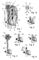
Figur 1- einen Teilschnitt durch ein Zweimassenschwungrad, bei dem ein erfindungsgemäß ausgebildetes, scheibenförmiges Bauteil Verwendung findet,
- Figur 1a
- eine Vergrößerung der Trennstelle eines erfindungsgemäßen, schwingungsisolierenden, scheibenförmigen Bauteils,
- Fig. 2 bis 6
- verschiedene Einzelheiten bzw. Ausführungsvarianten von schwingungsisolierenden, scheibenförmigen Bauteilen, die aus wenigstens zwei ringartigen Elementen bestehen.
- Fig. 7 bis 13
- in Ansicht verschiedene Ausführungsvarianten von Trennstellenführungen zwischen den ringartigen Elementen erfindungsgemäß ausgebildeter, schwingungsisolierender, scheibenförmiger Bauteile.
- FIG. 1
- a partial section through a dual mass flywheel, in which an inventively designed, disc-shaped component is used,
- FIG. 1a
- an enlargement of the separation point of a vibration-isolating disk-shaped component according to the invention,
- Fig. 2 to 6
- various details or variants of vibration-isolating disk-shaped components, which consist of at least two ring-like elements.
- Fig. 7 to 13
- in view of various embodiments of separation point guides between the ring-like elements according to the invention formed, vibration-insulating, disc-shaped components.
In Figur 1 ist teilweise und im Schnitt eine Drehmomentübertragungseinrichtung dargestellt,
die im vorliegenden Falle ein so genanntes Zweimassenschwungrad 1 bildet. Das Zweimassenschwungrad
1 besteht aus einer Primärschwungmasse 2 sowie einer Sekundärschwungmasse
3. Die Primärschwungmasse 2 ist mit einer nicht dargestellten Abtriebswelle einer
Brennkraftmaschine befestigbar, und zwar bei dem dargestellten Ausführungsbeispiel mittels
einer Mehrzahl von Schrauben 4, die umfangsmäßig verteilt sind. Das Zweimassenschwungrad
1 ist um eine Rotationsachse 5 verdrehbar. Die beiden Schwungmassen 2 und 3 sind über
eine Lagerung 6, die hier durch eine Gleitlagerung gebildet ist, verdrehbar zueinander gelagert,
wobei die Lagerung 6 radial innerhalb der Schrauben 4 angeordnet ist.FIG. 1 shows a partial and sectional view of a torque transmission device,
which forms a so-called
Auf der Sekundärschwungmasse 3 ist unter Zwischenlegung einer Kupplungsscheibe 7 eine
Reibungskupplung 8 befestigt. Mittels der Reibungskupplung 8 und der Kupplungsscheibe 7
ist das Zweimassenschwungrad 1 mit einer nicht näher dargestellten Eingangswelle eines Getriebes
verbindbar und von dieser wiederum trennbar.On the
Zwischen den beiden Schwungmassen 2 und 3 ist eine Dämpfungseinrichtung 9 wirksam,
welche Energiespeicher 10 umfasst, die bei dem dargestellten Ausführungsbeispiel durch
Schraubenfedern gebildet sind.Between the two
Die beiden Schwungmassen 2 und 3 besitzen Beaufschlagungsbereiche, mittels derer die
Energiespeicher 10 komprimierbar sind. Bei dem dargestellten Ausführungsbeispiel sind die
an der Primärschwungmasse 2 vorgesehenen Beaufschlagungsbereiche in an sich bekannter
Weise durch in die die Primärschwungmasse bildenden Bauteile 11, 12 eingebrachte Anformungen
gebildet. Die von der Sekundärschwungmasse 3 getragenen Beaufschlagungsbereiche
sind bei dem dargestellten Ausführungsbeispiel durch die radial äußeren Bereiche 13 eines
flanschartigen Bauteils 14 gebildet, welches radial innen über Niete 15 mit dem eine Reibfläche
für die Kupplungsscheibe 7 bildenden, ringförmigen Massenbauteil 16 fest verbunden
ist. Die Beaufschlagungsbereiche 13 sind durch radiale Arme bzw. Ausleger des flanschartigen
Bauteils 14 gebildet.The two
Das vorzugsweise durch Kaltumformung von Blechmaterial hergestellte Bauteil 12 dient zur
Befestigung der Primärschwungmasse 2 bzw. des gesamten Zweimassenschwungrades 1 an
der Antriebswelle einer Brennkraftmaschine. Radial außen besitzt das Bauteil 12 einen hier
einstückig ausgebildeten, axialen Ansatz 17, an dem das hier ebenfalls aus Blech hergestellte,
ringförmige Bauteil 11 befestigt ist. Die beiden Bauteile 11 und 12 bilden einen ringförmigen
Raum 18, der zumindest teilweise mit einem viskosen Medium, wie beispielsweise Fett,
gefülft sein kann.The preferably produced by cold forming sheet
Bezüglich des prinzipiellen, weiteren Aufbaus und der Wirkungsweise derartiger Schwingungsdämpfer wird auf die DE 37 21 705 A1, DE 37 21 712 A1, DE 37 21 711 A1, DE 40 18 321 A1, DE 41 17 584 A1, 41 17 582 A1 und DE 41 17 579 A1 verwiesen.Regarding the basic, further construction and the mode of action of such vibration dampers is to DE 37 21 705 A1, DE 37 21 712 A1, DE 37 21 711 A1, DE 40 18 321 A1, DE 41 17 584 A1, 41 17 582 A1 and DE 41 17 579 A1.
Das hier zur Drehmomenteinleitung in das Zweimassenschwungrad 1 dienende, scheibenförmige
bzw. ringartige Bauteil 12 ist derart aufgebaut bzw. ausgebildet, dass die im Endbereich
der mit diesem Bauteil 12 verbundenen Antriebswelle, wie insbesondere Kurbelwelle einer
Brennkraftmaschine, auftretenden Axial- und Biegeschwingungen zumindest teilweise gefiltert
bzw. gedämpft werden. Dadurch können die durch derartige Schwingungen erzeugten Anregungen,
welche normalerweise auf die Primärschwungmasse 2 übertragen werden und Axialsowie
Taumelschwingungen dieser Schwungmasse bewirken, auf ein zumindest akzeptables
Maß reduziert werden.The here for torque introduction in the
Um eine zumindest teilweise schwingungsmäßige Entkoppelung der die Primärschwungmasse
2 bildenden Bauteile gegenüber den im Endbereich der Abtriebswelle einer Brennkraftmaschine
vorhandenen Schwingungen zu erzielen, ist das scheibenförmige Bauteil 12 in wenigstens
zwei ringartige Elemente 19, 20 unterteilt, die bei dem in Figur 1 dargestellten Ausführungsbeispiel
unmittelbar aufeinander zentriert sind. Das innere, ringartige Element 20 besitzt
Ausnehmungen 21 zur Durchführung der Befestigungsschrauben 4. Das hier dargestellte, ringartige
Innenelement 20 besitzt weiterhin einen einstückig angeformten, axialen Ansatz 22, an
dem die Sekundärschwungmasse 3 gelagert ist, und zwar bei dem dargestellten Ausführungsbeispiel
über eine Gleitlagerung. Der axiale Ansatz 22 könnte jedoch auch durch ein getrenntes
Bauteil gebildet sein, das einen radial verlaufenden Flansch aufweisen könnte, der
ebenfalls mittels der Schrauben 4 axial verspannt werden könnte, zum Beispiel gegen ein
dann lediglich scheibenartig ausgebildetes Innenelement 20.To an at least partially vibrational decoupling of the
Das ringartige Außenelement 19 dient zur Bildung des ringförmigen Raumes 18 und zur Beaufschlagung
der Energiespeicher 10. The ring-like
In besonders vorteilhafter Weise können die beiden Elemente 19 und 20 zunächst aus einem
gleichen Flachmaterial, also zusammenhängend, hergestellt und danach durch einen Trennschnitt
separiert werden. Ein derartiger Trennschnitt kann beispielsweise mittels eines Stanzwerkzeuges,
also durch eine Stanzoperation, erfolgen. Nach einem derartigen Trennen der
zunächst einstückig miteinander verbundenen Elemente 19 und 20 können diese wiederum in
die in Figur 1 dargestellte Relativposition aufeinander geschoben bzw. zurückgedrückt werden.
Dieser Vorgang kann unmittelbar nach erfolgter Trennung und in vorteilhafter Weise in
der gleichen Stanzstufe erfolgen. Für manche Anwendungsfälle kann es auch vorteilhaft sein,
wenn nach dem Zusammenfügen der beiden Elemente 19 und 20 diese zumindest geringfügig
axial zueinander versetzt angeordnet sind, da dadurch durch entsprechende Ausgestaltung
der Trennflächen eine bessere Reib- und/oder formschlüssige Verbindung zwischen den
beiden Elementen 19 und 20 erzielbar ist.In a particularly advantageous manner, the two
Besonders vorteilhaft kann es sein, wenn das verwendete Trennverfahren gewährleistet, dass
beim wieder Aufeinanderdrücken bzw. Aufeinanderpressen der beiden Elemente 19, 20 im
Bereich der an diesen Elementen 19, 20 gebildeten Trennflächen eine zumindest reibschlüssige
Verbindung entsteht. Um die durch Aufeinanderpressen der beiden Elemente 19, 20 herzustellende
Verbindung, welche eine Drehmomentübertragung zwischen diesen beiden Elementen
19, 20 gewährleisten soll, zu verbessem, kann es vorteilhaft sein, wenn mittels des
Trennverfahrens Trennflächen entstehen, die eine gewisse Rauhigkeit bzw. Oberflächenausbrüche
besitzen. Dadurch kann beim Aufeinanderpressen der beiden Elemente 19, 20 auch
zumindest eine Vielzahl von kleinen formschlüssigen Verbindungen entstehen.It may be particularly advantageous if the separation method used ensures that
when pressing back on each other or pressing together of the two
Wie aus Figur 1 ersichtlich ist, ist die Trennstelle 23 zwischen den beiden ringartigen Elementen
19, 20 radial verhältnismäßig nahe an den Schrauben 4 bzw. den Ausnehmungen 21 vorgesehen.As can be seen from Figure 1, the
Zur axialen Sicherung der beiden ringartigen Elemente 19 und 20 sind bei dem in Figur 1 dargestellten
Ausführungsbeispiel beidseits des ringförmigen Bauteils 12 Scheiben 24, 25 angeordnet,
die hier ebenfalls mittels der Schrauben 4 bei Montage des Zweimassenschwungrades
1 auf die Abtriebswelle einer Brennkraftmaschine axial verspannt werden. Hierfür besitzen
die Scheiben 24, 25 ebenfalls entsprechende Ausnehmungen für die Schrauben 4.For the axial securing of the two ring-
Wie in Zusammenhang mit Figur 1 a ersichtlich ist, kann es auch besonders vorteilhaft sein,
wenn die eine Trennstelle 23 bildenden Trennflächen der beiden Elemente 19, 20 zumindest
über einen Teilbereich der Materialdicke 26 einen in Achsrichtung der ringartigen Elemente
19, 20 kegelstumpfartig bzw. konusartig verlaufenden Abschnitt bilden, wodurch zumindest in
einer axialen Relativbewegungsmöglichkeit zwischen den beiden ringartigen Elementen 19,
20 eine formschlüssige Verbindung gebildet wird. Bei dem dargestelften Ausführungsbeispiel
erstreckt sich die Trennstelle 23 praktisch über die gesamte Dicke 26 kegelstumpfartig, und
zwar entsprechend dem idealisiert dargestelften Keilwinkel 27. Bei einer Ausgestaltung der
Trennstelle 23 gemäß Figur 1a kann evtl. die auf der linken Seite vorgesehene Sicherungsscheibe
24 entfallen, da nach der Montage des ringartigen Innenelementes 20 auf der entsprechenden
Welle das Außenelement 19 in Richtung nach links durch die besondere Ausgestaltung
der Trennstelle 23 axial gesichert ist. Es ist also dann lediglich eine formschlüssige,
axiale Verbindung auf der Seite des durch die beiden Elemente 19, 20 gebildeten, scheibenförmigen
Bauteils notwendig, welche der fiktiven Spitze des kegelstumpfförmigen Abschnittes
der Trennstelle 23 zugewandt ist. bei dem dargestellten Ausführungsbeispiel ist die
erwähnte formschlüssige Verbindung durch die Scheibe 25 gewährleistet. Eine derartige
formschlüssige Verbindung könnte aber auch durch zumindest partiell im Bereich der Trennstelle
23 eingebrachte und über den Umfang verteilte Materialverformungen, wie zum Beispiel
Materialverstemmungen, gebildet sein. Eine derartige Materialverformung kann jedoch auch
über den gesamten Umfang der Trennstelle 23 an zumindest einem der Elemente 19, 20 eingebracht
werden. In Figur 4 ist eine derartige Verformung bzw. Verstemmung im Bereich einer
Trennstelle 423 mit dem Bezugszeichen 428 gekennzeichnet. Bei dem dargestellten Ausführungsbeispiel
gemäß Figur 4 ist lediglich auf der rechten Seite zumindest eine Materialverformung
bzw. -verstemmung angedeutet. Die ringartigen Elemente 419, 420 könnten jedoch
auch mittels beidseits derselben vorgesehenen Materialverformungen zueinander axial gesichert
sein.As can be seen in connection with FIG. 1 a, it can also be particularly advantageous
if the
Wie aus Figur 1 ersichtlich ist, besitzen die Sicherungsscheiben 24, 25 eine unterschiedliche
Materialdicke. Das eine derartige Scheibe bildende Material kann derart ausgewählt werden
und bezüglich der Dicke derart dimensioniert sein, dass die entsprechende Scheibe axiale
Federeigenschaften aufweist.As can be seen from Figure 1, the
Bei der in Figur 2 dargestellten Ausführungsform sind zwei Sicherungsscheiben 24, 24a vorgesehen,
welche identisch ausgebildet sind. Zwischen der Sicherungsscheibe 24a und den
Köpfen der Schrauben 4 ist eine Unterlegscheibe 30 vorgesehen. In vorteilhafter Weise kann
die Unterlegscheibe 30 ringförmig ausgebildet sein und für alle Schrauben 4 als Unterlegscheibe
dienen. In the embodiment shown in Figure 2, two
Bei der in Figur 3 dargestellten Ausführungsform ist die Trennstelle 323 zwischen dem äußeren
ringartigen Element 319 und dem inneren ringartigen Element 320 auf einem verhältnismäßig
großen Durchmesser angeordnet. Wie bereits erwähnt, könnte das durch die ringartigen
Elemente 319, 320 gebildete, scheibenförmige Bauteil 312 auch mehr als eine sich über
den Umfang erstreckende Trennstelle 323 aufweisen. So könnte beispielsweise bei einer Ausführungsform
gemäß Figur 3 auch eine der Trennstelle 23 gemäß Figur 1 entsprechende
Trennstelle radial außerhalb der Schrauben 324 und angrenzend an diese vorgesehen werden.In the embodiment shown in Figure 3, the
Bei der in Figur 5 dargestellten Ausführungsform wird die axiale Sicherung zwischen dem
ringartigen Innenelement 520 und dem ringartigen Außenelement 519 mittels mehrerer, über
den Umfang im Bereich der entsprechenden Trennstelle vorgesehener Nieten 531 gewährleistet.In the embodiment shown in Figure 5, the axial securing between the
ring-like
Bei der Ausführungsform gemäß Figur 6 ist zwischen dem ringartigen Innenelement 620 und
dem ringartigen Außenelement 619 zumindest ein radial zwischengelegtes Bauteil 632 vorgesehen.
Das Bauteil 632 kann in vorteilhafter Weise durch ein Drahtformstück gebildet sein,
wobei der Draht zum Beispiel einen ringförmigen Querschnitt aufweisen kann. Dieses Drahtformstück
632 kann sich zumindest annähernd über den gesamten Umfang der Trennstelle
623 erstrecken, also praktisch ringförmig ausgebildet sein. Es können jedoch auch mehrere
sektorförmige Drahtformstücke, welche über den Umfang verteilt sind, vorgesehen werden.
Auch könnten einzelne, über den Umfang, vorzugsweise gleichmäßig verteilte Kugeln radial
zwischen den beiden Elementen 619, 620 vorgesehen werden. Die zwischen den beiden
Elementen 619 und 620 vorgesehenen Bauteile können zwischen die beiden Elemente eingepresst
werden. Zur Bildung des für die Teile 632 erforderlichen Bauraumes werden die Konturen
der Elemente 619, 620 entsprechend gestanzt, und falls erforderlich, durch Prägen geformt.
Zur axialen Sicherung zwischen den einzelnen Teilen 619, 632, 620 können, wie bereits
in Zusammenhang mit den anderen Ausgestaltungsformen beschrieben, zusätzliche Sicherungsscheiben
oder aber Materialverformungen, die einen axialen Zusammenhalt gewährleisten,
verwendet werden.In the embodiment according to Figure 6 is between the annular
Obwohl es vorteilhaft sein kann, wenn die ringartigen Innen- und Außenelemente aus dem gleichen Material hergestellt werden, kann es für manche Anwendungsfälle auch zweckmäßig sein, wenn die Teile aus verschiedenen Materialien bestehen, welche die gewünschten Eigenschaften, zum Beispiel Elastizität und/oder Wärmeausdehnungskoeffizient und/oder Wärmeleitungskoeffizient, aufweisen. So kann beispielsweise zur Bildung zumindest eines dieser Elemente auch Aluminium oder Stahlguss verwendet werden.Although it may be advantageous if the ring-like inner and outer elements of the same material can be made, it may also be appropriate for some applications when the parts are made of different materials, which have the desired properties, for example elasticity and / or thermal expansion coefficient and / or coefficient of thermal conductivity, exhibit. For example, at least one of these can be used to form Elements can also be used aluminum or cast steel.
Bei Verwendung von unterschiedlichen Materialien, wie zum Beispiel Federstahl und Baustahl, können die ein scheibenförmiges Bauteil bildenden Elemente auch mittels Schweißverbindungen, insbesondere Laserstrahlschweißverbindungen, miteinander verbunden werden. Die entsprechenden Schweißverbindungen können dabei auch stellenweise und über den Umfang verteilt vorgesehen werden. Es kann jedoch auch eine durchgehende Schweißnaht Verwendung finden.When using different materials, such as spring steel and structural steel, the elements forming a disk-shaped component can also be welded by means of welded connections, In particular laser beam welding connections are connected to each other. The corresponding welds can also locally and over the Scope be provided distributed. However, it can also be a continuous weld Find use.
Bei einer Ausgestaltung gemäß Figur 6, bei der zwischen den das scheibenförmige Bauteil
619 bildenden ringartigen Elementen zumindest ein Zwischenstück 632 vorgesehen ist, können
zur Bildung eines derartigen Zwischenstücks auch Kunststoffteile bzw. Hartgummiteile
verwendet werden. Diese Teile sind dabei vorzugsweise hitzeresistent.In an embodiment according to Figure 6, in which between the disc-shaped
Obwohl es für viele Anwendungsfälle ausreichend sein kann, wenn die eine Trennstelle 23,
323, 423, 623 bildenden und sich radial gegenüber liegenden Flächen der übereinander angeordneten,
ringartigen Elemente eine praktisch kreisringförmige Gestalt aufweisen, kann es
für eine Vielzahl von Anwendungsfällen zweckmäßig sein, wenn die diese Trennstellen bildenden
Flächen zwar einen mit der Rotationsachse 5 des entsprechenden scheibenförmigen
Bauteils zumindest annähernd zusammenfallenden Mittelpunkt aufweisen, jedoch einen von
einer Kreisform abweichenden Verlauf besitzen. So könnte beispielsweise die Trennstelle 23
bzw. die diese bildenden Trennflächen der Elemente 19 und 20 eine ovafförmige Gestalt besitzen.
Weitere Ausgestaltungsformen derartiger Trennstellen bzw. Trennflächen sind in den
Figuren 7 bis 9 dargestellt. In Figur 7 ist der Verlauf der Trennstelle 23 wellenförmig über den
Umfang ausgebildet. Durch den gleichmäßigen, wellenförmigen Verlauf der Trennstelle 23
werden am radial inneren Rand des Außenelementes 19 und am radial äußeren Rand des Innenelementes
20 abgerundete Zähne gebildet, die radial ineinander greifen und zur Erhöhung
des übertragbaren Drehmomentes dienen. Durch den gewellten Verlauf der Trennstelle 23
wird auch die wirksame Länge bzw. Fläche dieser Trennstelle 23 vergrößert.Although it may be sufficient for many applications, if the one
In Figur 8 ist eine ähnliche Trennstelle 23a dargestellt, wobei diese jedoch derart geführt ist,
dass radial ineinander greifende Keilverzahnungen an den Elementen 19, 20 gebildet sind.FIG. 8 shows a
In Figur 9 ist die zwischen den beiden Elementen 19, 20 verlaufende Trennstelle 23b polygonartig
ausgebildet. In Figure 9, the
Bei der Ausgestaltung gemäß Figur 10 ist die Trennstelle 23c kreisförmig ausgebildet.In the embodiment according to FIG. 10, the
Figur 11 zeigt eine umfangsmäßige Verteilung von Nieten 531 gemäß Figur 5. Wie bereits erwähnt,
dienen derartige Niete zur axialen Sicherung der beiden Elemente 519, 520. Gleichzeitig
können die Niete 531 das übertragbare Drehmoment erhöhen.FIG. 11 shows a circumferential distribution of
In Figur 12 ist die Trennstelle 623 gemäß Figur 6 dargestellt. Dabei ist die Führung der Trennstelle
623 polygonartig ausgebildet und der zwischen den beiden Elementen 619, 620 angeordnete
Drahtring 632 hat eine entsprechend angepasste, polygonartige Ausgestaltung.FIG. 12 shows the
In Figur 13 ist noch eine Ausführungsform dargestellt, bei der anstatt von Nieten 531, wie in
Figur 11, eine Vielzahl von aus Kunststoff oder Hartgummi bestehenden Zwischenelementen
731 im Bereich einer Trennstelle 723 vorgesehen sind. Bei dem dargestellten Ausführungsbeispiel
sind die Elemente 719, 720 derart ausgestaltet, dass sie im Bereich der Trennstelle
723 in ähnlicher Weise Kontakt haben, wie dies in Zusammenhang mit Figur 1 für die Trennstelle
23 beschrieben wurde. Durch entsprechende Wahl der Festigkeit der Zwischenelemente
731 könnte im Bereich der Trennstelle 723 zwischen Zwischenelementen 731 auch zumindest
ein geringer radialer Spalt vorhanden sein. Zweckmäßig kann es auch sein, wenn ein derartiger
Spalt nur stellenweise im Bereich der Trennstelle 723 zwischen benachbarten Zwischenelementen
731 vorhanden ist. FIG. 13 shows an embodiment in which, instead of
- 11
- ZweimassenschwungradDual Mass Flywheel
- 22
- PrimärschwungmassePrimary flywheel
- 33
- SekundärschwungmasseSecondary flywheel mass
- 44
- Schraubenscrew
- 55
- Rotationsachseaxis of rotation
- 66
- Lagerungstorage
- 77
- Kupplungsscheibeclutch disc
- 88th
- Reibungskupplungfriction clutch
- 99
- Dämpfungseinrichtungattenuator
- 1010
- Energiespeicherenergy storage
- 1111
- Bauteilcomponent
- 1212
- Bauteilcomponent
- 1313
- Beaufschlagungsbereicheimpingement
- 1414
- flanschartiges Bauteilflange-like component
- 1515
- Nieterivet
- 1616
- Massenbauteilmass element
- 1717
- axialer Ansatzaxial approach
- 1818
- Raumroom
- 1919
- ringartiges Außenelementring-like outer element
- 2020
- ringartiges Innenelementring-like interior element
- 2121
- Ausnehmungenrecesses
- 2222
- axialer Ansatzaxial approach
- 2323
- Trennstelleseparation point
- 23a23a
- Trennstelleseparation point
- 23b23b
- Trennstelleseparation point
- 23c23c
- Trennstelleseparation point
- 2424
- Sicherungsscheibenlock washers
- 24a24a
- Sicherungsscheibenlock washers
- 2525
- Scheibenslices
- 2626
- Materialdickematerial thickness
- 2727
- Keilwinkelwedge angle
- 3030
- Unterlegscheibewasher
- 312312
- scheibenförmiges Bauteil disc-shaped component
- 319319
- ringartiges Elementring-like element
- 320320
- ringartiges Elementring-like element
- 323323
- Trennstelleseparation point
- 324324
- Schraubenscrew
- 419419
- ringartiges Elementring-like element
- 420420
- ringartiges Elementring-like element
- 423423
- Trennstelleseparation point
- 428428
- Materialverformungmaterial deformation
- 519519
- ringartiges Außenelementring-like outer element
- 520520
- ringartiges Innenelementring-like interior element
- 531531
- Nietenrivet
- 619619
- ringartiges Außenelementring-like outer element
- 620620
- ringartiges Innenelementring-like interior element
- 623623
- Trennstelleseparation point
- 632632
- Zwischenstück; DrahtringAdapter; wire ring
- 719719
- Elementeelements
- 720720
- Elementeelements
- 723723
- Trennstelleseparation point
- 731731
- Zwischenelementeintermediate elements
Claims (24)
Applications Claiming Priority (2)
| Application Number | Priority Date | Filing Date | Title |
|---|---|---|---|
| DE102004012321 | 2004-03-11 | ||
| DE102004012321 | 2004-03-11 |
Publications (2)
| Publication Number | Publication Date |
|---|---|
| EP1574744A1 true EP1574744A1 (en) | 2005-09-14 |
| EP1574744B1 EP1574744B1 (en) | 2007-11-14 |
Family
ID=34813683
Family Applications (1)
| Application Number | Title | Priority Date | Filing Date |
|---|---|---|---|
| EP05003945A Not-in-force EP1574744B1 (en) | 2004-03-11 | 2005-02-23 | Vibration isolating disc-shaped component |
Country Status (5)
| Country | Link |
|---|---|
| EP (1) | EP1574744B1 (en) |
| KR (1) | KR20060043482A (en) |
| CN (1) | CN1667293B (en) |
| AT (1) | ATE378532T1 (en) |
| DE (2) | DE502005001920D1 (en) |
Cited By (3)
| Publication number | Priority date | Publication date | Assignee | Title |
|---|---|---|---|---|
| GB2425581B (en) * | 2004-03-11 | 2008-06-04 | Automotive Products S P A | Twin mass flywheels |
| WO2008074399A1 (en) | 2006-12-18 | 2008-06-26 | Borgwarner Inc. | Torsional vibration damper comprising a sectional primary element |
| KR20110101235A (en) * | 2009-01-08 | 2011-09-15 | 발레오 앙브라이아쥐 | Double damping flywheel with double damping means, notably for a motor vehicle |
Families Citing this family (2)
| Publication number | Priority date | Publication date | Assignee | Title |
|---|---|---|---|---|
| DE102005062318A1 (en) * | 2005-12-24 | 2007-07-12 | Schaeffler Kg | Traction drive for an internal combustion engine |
| DE102014006291B3 (en) | 2014-04-26 | 2015-09-03 | Audi Ag | rotary damper |
Citations (3)
| Publication number | Priority date | Publication date | Assignee | Title |
|---|---|---|---|---|
| DE19825249A1 (en) * | 1998-06-05 | 1999-12-09 | Mannesmann Sachs Ag | Torsion vibration damper e.g. for twin mass flywheels |
| DE10002259A1 (en) * | 1999-01-25 | 2000-07-27 | Luk Lamellen & Kupplungsbau | Torque transmission unit comprises at least one axially elastic component in the form of a disk or an annulus provided with a number of circumferentially distributed axial separation sections |
| DE10109248A1 (en) * | 2001-02-26 | 2002-09-05 | Zf Sachs Ag | Dual Mass Flywheel |
Family Cites Families (1)
| Publication number | Priority date | Publication date | Assignee | Title |
|---|---|---|---|---|
| BR9909444A (en) * | 1998-04-06 | 2000-12-12 | Luk Lamellen & Kupplungsbau | Split flywheel |
-
2005
- 2005-02-23 DE DE502005001920T patent/DE502005001920D1/en active Active
- 2005-02-23 EP EP05003945A patent/EP1574744B1/en not_active Not-in-force
- 2005-02-23 AT AT05003945T patent/ATE378532T1/en not_active IP Right Cessation
- 2005-02-23 DE DE200510008381 patent/DE102005008381A1/en not_active Withdrawn
- 2005-03-08 KR KR1020050018913A patent/KR20060043482A/en not_active Application Discontinuation
- 2005-03-11 CN CN200510054718.XA patent/CN1667293B/en not_active Expired - Fee Related
Patent Citations (3)
| Publication number | Priority date | Publication date | Assignee | Title |
|---|---|---|---|---|
| DE19825249A1 (en) * | 1998-06-05 | 1999-12-09 | Mannesmann Sachs Ag | Torsion vibration damper e.g. for twin mass flywheels |
| DE10002259A1 (en) * | 1999-01-25 | 2000-07-27 | Luk Lamellen & Kupplungsbau | Torque transmission unit comprises at least one axially elastic component in the form of a disk or an annulus provided with a number of circumferentially distributed axial separation sections |
| DE10109248A1 (en) * | 2001-02-26 | 2002-09-05 | Zf Sachs Ag | Dual Mass Flywheel |
Cited By (3)
| Publication number | Priority date | Publication date | Assignee | Title |
|---|---|---|---|---|
| GB2425581B (en) * | 2004-03-11 | 2008-06-04 | Automotive Products S P A | Twin mass flywheels |
| WO2008074399A1 (en) | 2006-12-18 | 2008-06-26 | Borgwarner Inc. | Torsional vibration damper comprising a sectional primary element |
| KR20110101235A (en) * | 2009-01-08 | 2011-09-15 | 발레오 앙브라이아쥐 | Double damping flywheel with double damping means, notably for a motor vehicle |
Also Published As
| Publication number | Publication date |
|---|---|
| ATE378532T1 (en) | 2007-11-15 |
| DE102005008381A1 (en) | 2005-09-29 |
| CN1667293B (en) | 2011-04-27 |
| DE502005001920D1 (en) | 2007-12-27 |
| CN1667293A (en) | 2005-09-14 |
| KR20060043482A (en) | 2006-05-15 |
| EP1574744B1 (en) | 2007-11-14 |
Similar Documents
| Publication | Publication Date | Title |
|---|---|---|
| DE19728422B4 (en) | Device for coupling in a drive train | |
| DE19912968A1 (en) | Torsional vibration damper for internal combustion engine | |
| DE19914376A1 (en) | Engine flywheel combined with electrical machine for engine starting, current generation or hybrid drive | |
| EP2340378B1 (en) | Torsional vibration damping arrangement, particularly for the power train of a vehicle | |
| DE102014217451A1 (en) | Centrifugal pendulum stop spring element, centrifugal pendulum device and component assembly | |
| EP3105464B1 (en) | Normally-engaged clutch device | |
| DE102015200766A1 (en) | Centrifugal pendulum device and torsional vibration damper | |
| EP2888505B1 (en) | Torsional vibration damper | |
| EP1574744B1 (en) | Vibration isolating disc-shaped component | |
| DE102009007829A1 (en) | Friction clutch for a torque transmission device | |
| EP3111102B2 (en) | Coupling device | |
| EP2347145B1 (en) | Torsional vibration damper for the drive train of a vehicle | |
| DE4117580C2 (en) | Torque transfer device | |
| EP2912339B1 (en) | Torsional vibration damper | |
| EP0952374B1 (en) | Torsional vibration damper and its method of manufacture | |
| EP1503103B1 (en) | Torsional vibration damper | |
| DE8605603U1 (en) | Torsional vibration damper | |
| DE102015218636A1 (en) | torsional vibration dampers | |
| DE69508224T2 (en) | TORQUE DAMPER, ESPECIALLY FOR MOTOR VEHICLES | |
| EP1771671B1 (en) | Two-mass flywheel with a primary mass, a spring system and a secondary mass | |
| DE19982216B4 (en) | Dual mass damping flywheel, especially for motor vehicles | |
| EP1647729A2 (en) | Coupling device for multiple disc clutch | |
| EP3280930B1 (en) | Centrifugal pendulum | |
| DE19711145B4 (en) | Torsion damper with washer, especially for motor vehicles | |
| DE102021116063A1 (en) | Hybrid module for a hybrid drive train |
Legal Events
| Date | Code | Title | Description |
|---|---|---|---|
| PUAI | Public reference made under article 153(3) epc to a published international application that has entered the european phase |
Free format text: ORIGINAL CODE: 0009012 |
|
| AK | Designated contracting states |
Kind code of ref document: A1 Designated state(s): AT BE BG CH CY CZ DE DK EE ES FI FR GB GR HU IE IS IT LI LT LU MC NL PL PT RO SE SI SK TR |
|
| AX | Request for extension of the european patent |
Extension state: AL BA HR LV MK YU |
|
| 17P | Request for examination filed |
Effective date: 20060314 |
|
| AKX | Designation fees paid |
Designated state(s): AT BE BG CH CY CZ DE DK EE ES FI FR GB GR HU IE IS IT LI LT LU MC NL PL PT RO SE SI SK TR |
|
| GRAP | Despatch of communication of intention to grant a patent |
Free format text: ORIGINAL CODE: EPIDOSNIGR1 |
|
| GRAS | Grant fee paid |
Free format text: ORIGINAL CODE: EPIDOSNIGR3 |
|
| GRAA | (expected) grant |
Free format text: ORIGINAL CODE: 0009210 |
|
| AK | Designated contracting states |
Kind code of ref document: B1 Designated state(s): AT BE BG CH CY CZ DE DK EE ES FI FR GB GR HU IE IS IT LI LT LU MC NL PL PT RO SE SI SK TR |
|
| REG | Reference to a national code |
Ref country code: GB Ref legal event code: FG4D Free format text: NOT ENGLISH |
|
| REG | Reference to a national code |
Ref country code: CH Ref legal event code: EP |
|
| REG | Reference to a national code |
Ref country code: IE Ref legal event code: FG4D Free format text: LANGUAGE OF EP DOCUMENT: GERMAN |
|
| REF | Corresponds to: |
Ref document number: 502005001920 Country of ref document: DE Date of ref document: 20071227 Kind code of ref document: P |
|
| PG25 | Lapsed in a contracting state [announced via postgrant information from national office to epo] |
Ref country code: SE Free format text: LAPSE BECAUSE OF FAILURE TO SUBMIT A TRANSLATION OF THE DESCRIPTION OR TO PAY THE FEE WITHIN THE PRESCRIBED TIME-LIMIT Effective date: 20080214 Ref country code: ES Free format text: LAPSE BECAUSE OF FAILURE TO SUBMIT A TRANSLATION OF THE DESCRIPTION OR TO PAY THE FEE WITHIN THE PRESCRIBED TIME-LIMIT Effective date: 20080225 Ref country code: NL Free format text: LAPSE BECAUSE OF FAILURE TO SUBMIT A TRANSLATION OF THE DESCRIPTION OR TO PAY THE FEE WITHIN THE PRESCRIBED TIME-LIMIT Effective date: 20071114 |
|
| NLV1 | Nl: lapsed or annulled due to failure to fulfill the requirements of art. 29p and 29m of the patents act | ||
| PG25 | Lapsed in a contracting state [announced via postgrant information from national office to epo] |
Ref country code: FI Free format text: LAPSE BECAUSE OF FAILURE TO SUBMIT A TRANSLATION OF THE DESCRIPTION OR TO PAY THE FEE WITHIN THE PRESCRIBED TIME-LIMIT Effective date: 20071114 Ref country code: LT Free format text: LAPSE BECAUSE OF FAILURE TO SUBMIT A TRANSLATION OF THE DESCRIPTION OR TO PAY THE FEE WITHIN THE PRESCRIBED TIME-LIMIT Effective date: 20071114 Ref country code: SI Free format text: LAPSE BECAUSE OF FAILURE TO SUBMIT A TRANSLATION OF THE DESCRIPTION OR TO PAY THE FEE WITHIN THE PRESCRIBED TIME-LIMIT Effective date: 20071114 Ref country code: PL Free format text: LAPSE BECAUSE OF FAILURE TO SUBMIT A TRANSLATION OF THE DESCRIPTION OR TO PAY THE FEE WITHIN THE PRESCRIBED TIME-LIMIT Effective date: 20071114 Ref country code: BG Free format text: LAPSE BECAUSE OF FAILURE TO SUBMIT A TRANSLATION OF THE DESCRIPTION OR TO PAY THE FEE WITHIN THE PRESCRIBED TIME-LIMIT Effective date: 20080214 Ref country code: IS Free format text: LAPSE BECAUSE OF FAILURE TO SUBMIT A TRANSLATION OF THE DESCRIPTION OR TO PAY THE FEE WITHIN THE PRESCRIBED TIME-LIMIT Effective date: 20080314 |
|
| GBV | Gb: ep patent (uk) treated as always having been void in accordance with gb section 77(7)/1977 [no translation filed] | ||
| ET | Fr: translation filed | ||
| PG25 | Lapsed in a contracting state [announced via postgrant information from national office to epo] |
Ref country code: DK Free format text: LAPSE BECAUSE OF FAILURE TO SUBMIT A TRANSLATION OF THE DESCRIPTION OR TO PAY THE FEE WITHIN THE PRESCRIBED TIME-LIMIT Effective date: 20071114 Ref country code: CZ Free format text: LAPSE BECAUSE OF FAILURE TO SUBMIT A TRANSLATION OF THE DESCRIPTION OR TO PAY THE FEE WITHIN THE PRESCRIBED TIME-LIMIT Effective date: 20071114 |
|
| PGFP | Annual fee paid to national office [announced via postgrant information from national office to epo] |
Ref country code: FR Payment date: 20080215 Year of fee payment: 4 |
|
| PG25 | Lapsed in a contracting state [announced via postgrant information from national office to epo] |
Ref country code: RO Free format text: LAPSE BECAUSE OF FAILURE TO SUBMIT A TRANSLATION OF THE DESCRIPTION OR TO PAY THE FEE WITHIN THE PRESCRIBED TIME-LIMIT Effective date: 20071114 Ref country code: SK Free format text: LAPSE BECAUSE OF FAILURE TO SUBMIT A TRANSLATION OF THE DESCRIPTION OR TO PAY THE FEE WITHIN THE PRESCRIBED TIME-LIMIT Effective date: 20071114 |
|
| BERE | Be: lapsed |
Owner name: LUK LAMELLEN UND KUPPLUNGSBAU BETEILIGUNGS K.G. Effective date: 20080228 |
|
| PLBE | No opposition filed within time limit |
Free format text: ORIGINAL CODE: 0009261 |
|
| STAA | Information on the status of an ep patent application or granted ep patent |
Free format text: STATUS: NO OPPOSITION FILED WITHIN TIME LIMIT |
|
| PG25 | Lapsed in a contracting state [announced via postgrant information from national office to epo] |
Ref country code: PT Free format text: LAPSE BECAUSE OF FAILURE TO SUBMIT A TRANSLATION OF THE DESCRIPTION OR TO PAY THE FEE WITHIN THE PRESCRIBED TIME-LIMIT Effective date: 20080414 |
|
| REG | Reference to a national code |
Ref country code: IE Ref legal event code: FD4D |
|
| 26N | No opposition filed |
Effective date: 20080815 |
|
| PG25 | Lapsed in a contracting state [announced via postgrant information from national office to epo] |
Ref country code: IE Free format text: LAPSE BECAUSE OF FAILURE TO SUBMIT A TRANSLATION OF THE DESCRIPTION OR TO PAY THE FEE WITHIN THE PRESCRIBED TIME-LIMIT Effective date: 20071114 Ref country code: MC Free format text: LAPSE BECAUSE OF NON-PAYMENT OF DUE FEES Effective date: 20080228 |
|
| PG25 | Lapsed in a contracting state [announced via postgrant information from national office to epo] |
Ref country code: GB Free format text: LAPSE BECAUSE OF FAILURE TO SUBMIT A TRANSLATION OF THE DESCRIPTION OR TO PAY THE FEE WITHIN THE PRESCRIBED TIME-LIMIT Effective date: 20071114 |
|
| PG25 | Lapsed in a contracting state [announced via postgrant information from national office to epo] |
Ref country code: GR Free format text: LAPSE BECAUSE OF FAILURE TO SUBMIT A TRANSLATION OF THE DESCRIPTION OR TO PAY THE FEE WITHIN THE PRESCRIBED TIME-LIMIT Effective date: 20080215 Ref country code: EE Free format text: LAPSE BECAUSE OF FAILURE TO SUBMIT A TRANSLATION OF THE DESCRIPTION OR TO PAY THE FEE WITHIN THE PRESCRIBED TIME-LIMIT Effective date: 20071114 |
|
| PG25 | Lapsed in a contracting state [announced via postgrant information from national office to epo] |
Ref country code: BE Free format text: LAPSE BECAUSE OF NON-PAYMENT OF DUE FEES Effective date: 20080228 |
|
| PG25 | Lapsed in a contracting state [announced via postgrant information from national office to epo] |
Ref country code: AT Free format text: LAPSE BECAUSE OF NON-PAYMENT OF DUE FEES Effective date: 20080223 |
|
| PG25 | Lapsed in a contracting state [announced via postgrant information from national office to epo] |
Ref country code: CY Free format text: LAPSE BECAUSE OF FAILURE TO SUBMIT A TRANSLATION OF THE DESCRIPTION OR TO PAY THE FEE WITHIN THE PRESCRIBED TIME-LIMIT Effective date: 20071114 |
|
| REG | Reference to a national code |
Ref country code: CH Ref legal event code: PL |
|
| PG25 | Lapsed in a contracting state [announced via postgrant information from national office to epo] |
Ref country code: LI Free format text: LAPSE BECAUSE OF NON-PAYMENT OF DUE FEES Effective date: 20090228 Ref country code: CH Free format text: LAPSE BECAUSE OF NON-PAYMENT OF DUE FEES Effective date: 20090228 |
|
| REG | Reference to a national code |
Ref country code: FR Ref legal event code: ST Effective date: 20091030 |
|
| PG25 | Lapsed in a contracting state [announced via postgrant information from national office to epo] |
Ref country code: FR Free format text: LAPSE BECAUSE OF NON-PAYMENT OF DUE FEES Effective date: 20090302 |
|
| PG25 | Lapsed in a contracting state [announced via postgrant information from national office to epo] |
Ref country code: LU Free format text: LAPSE BECAUSE OF NON-PAYMENT OF DUE FEES Effective date: 20080223 Ref country code: HU Free format text: LAPSE BECAUSE OF FAILURE TO SUBMIT A TRANSLATION OF THE DESCRIPTION OR TO PAY THE FEE WITHIN THE PRESCRIBED TIME-LIMIT Effective date: 20080515 |
|
| PG25 | Lapsed in a contracting state [announced via postgrant information from national office to epo] |
Ref country code: TR Free format text: LAPSE BECAUSE OF FAILURE TO SUBMIT A TRANSLATION OF THE DESCRIPTION OR TO PAY THE FEE WITHIN THE PRESCRIBED TIME-LIMIT Effective date: 20071114 |
|
| PG25 | Lapsed in a contracting state [announced via postgrant information from national office to epo] |
Ref country code: IT Free format text: LAPSE BECAUSE OF NON-PAYMENT OF DUE FEES Effective date: 20080229 |
|
| REG | Reference to a national code |
Ref country code: DE Ref legal event code: R081 Ref document number: 502005001920 Country of ref document: DE Owner name: SCHAEFFLER TECHNOLOGIES AG & CO. KG, DE Free format text: FORMER OWNER: SCHAEFFLER TECHNOLOGIES GMBH & CO. KG, 91074 HERZOGENAURACH, DE Effective date: 20120828 Ref country code: DE Ref legal event code: R081 Ref document number: 502005001920 Country of ref document: DE Owner name: SCHAEFFLER TECHNOLOGIES GMBH & CO. KG, DE Free format text: FORMER OWNER: SCHAEFFLER TECHNOLOGIES GMBH & CO. KG, 91074 HERZOGENAURACH, DE Effective date: 20120828 |
|
| REG | Reference to a national code |
Ref country code: DE Ref legal event code: R081 Ref document number: 502005001920 Country of ref document: DE Owner name: SCHAEFFLER TECHNOLOGIES AG & CO. KG, DE Free format text: FORMER OWNER: SCHAEFFLER TECHNOLOGIES AG & CO. KG, 91074 HERZOGENAURACH, DE Effective date: 20140218 Ref country code: DE Ref legal event code: R081 Ref document number: 502005001920 Country of ref document: DE Owner name: SCHAEFFLER TECHNOLOGIES GMBH & CO. KG, DE Free format text: FORMER OWNER: SCHAEFFLER TECHNOLOGIES AG & CO. KG, 91074 HERZOGENAURACH, DE Effective date: 20140218 |
|
| REG | Reference to a national code |
Ref country code: DE Ref legal event code: R081 Ref document number: 502005001920 Country of ref document: DE Owner name: SCHAEFFLER TECHNOLOGIES AG & CO. KG, DE Free format text: FORMER OWNER: SCHAEFFLER TECHNOLOGIES GMBH & CO. KG, 91074 HERZOGENAURACH, DE Effective date: 20150213 |
|
| PGFP | Annual fee paid to national office [announced via postgrant information from national office to epo] |
Ref country code: DE Payment date: 20180430 Year of fee payment: 14 |
|
| REG | Reference to a national code |
Ref country code: DE Ref legal event code: R119 Ref document number: 502005001920 Country of ref document: DE |
|
| PG25 | Lapsed in a contracting state [announced via postgrant information from national office to epo] |
Ref country code: DE Free format text: LAPSE BECAUSE OF NON-PAYMENT OF DUE FEES Effective date: 20190903 |
|
| P01 | Opt-out of the competence of the unified patent court (upc) registered |
Effective date: 20230523 |