EP1574455A1 - Emptying device for a bulk container and bulk container - Google Patents
Emptying device for a bulk container and bulk container Download PDFInfo
- Publication number
- EP1574455A1 EP1574455A1 EP04405150A EP04405150A EP1574455A1 EP 1574455 A1 EP1574455 A1 EP 1574455A1 EP 04405150 A EP04405150 A EP 04405150A EP 04405150 A EP04405150 A EP 04405150A EP 1574455 A1 EP1574455 A1 EP 1574455A1
- Authority
- EP
- European Patent Office
- Prior art keywords
- bulk material
- container
- closure
- bulk
- emptying device
- Prior art date
- Legal status (The legal status is an assumption and is not a legal conclusion. Google has not performed a legal analysis and makes no representation as to the accuracy of the status listed.)
- Withdrawn
Links
Images


Classifications
-
- B—PERFORMING OPERATIONS; TRANSPORTING
- B65—CONVEYING; PACKING; STORING; HANDLING THIN OR FILAMENTARY MATERIAL
- B65D—CONTAINERS FOR STORAGE OR TRANSPORT OF ARTICLES OR MATERIALS, e.g. BAGS, BARRELS, BOTTLES, BOXES, CANS, CARTONS, CRATES, DRUMS, JARS, TANKS, HOPPERS, FORWARDING CONTAINERS; ACCESSORIES, CLOSURES, OR FITTINGS THEREFOR; PACKAGING ELEMENTS; PACKAGES
- B65D90/00—Component parts, details or accessories for large containers
- B65D90/54—Gates or closures
- B65D90/62—Gates or closures having closure members movable out of the plane of the opening
- B65D90/626—Gates or closures having closure members movable out of the plane of the opening having a linear motion
-
- B—PERFORMING OPERATIONS; TRANSPORTING
- B65—CONVEYING; PACKING; STORING; HANDLING THIN OR FILAMENTARY MATERIAL
- B65D—CONTAINERS FOR STORAGE OR TRANSPORT OF ARTICLES OR MATERIALS, e.g. BAGS, BARRELS, BOTTLES, BOXES, CANS, CARTONS, CRATES, DRUMS, JARS, TANKS, HOPPERS, FORWARDING CONTAINERS; ACCESSORIES, CLOSURES, OR FITTINGS THEREFOR; PACKAGING ELEMENTS; PACKAGES
- B65D88/00—Large containers
- B65D88/54—Large containers characterised by means facilitating filling or emptying
- B65D88/72—Fluidising devices
Definitions
- the invention relates to an emptying device for emptying bulk material from a Bulk container and a bulk material container and a closure for a bulk material container.
- the Bulk solids discharged through trained in the container walls outlet openings.
- the bulk containers are typically to an emptying device (also referred to as outlet or docking device or outlet or docking station) connected, which is provided with an inlet opening, which in a passageway opens, through which the bulk material flows (also called outflow) can.
- a bulk material emptying device which a provided with an inlet connection housing, which with a Passage channel is provided.
- a provided with an outlet bulk container is so tightly connected to the connection housing that the bulk material when opened Outlet opening out of the bulk material container through the passage channel can flow out.
- the bulk material container is indeed comparatively close to those in the document EP 0 915 032 described emptying device connected.
- problems arise during emptying, by the Clumping in the bulk material container hampers the emptying process or even completely block.
- the document US Pat. No. 5,474,111 describes a bulk material emptying device, which includes a pointed lance.
- a pointed lance To empty a sack-shaped bulk container is the hollow lance pierced through the container wall, whereupon the bulk material through a plurality of inlet openings into a passage formed in the lance and flows out of it through the bulk material container.
- the lance is further provided with a nozzle, through which compressed air in the bulk material container can be blown into it to support the flow of bulk material.
- the object of the invention is a belonging to the aforementioned technical field Specify emptying device and a bulk material container, which dense Connection of the bulk material container to the emptying device and a reliable Allow emptying and removal of bulk materials from the bulk material container.
- an emptying device for emptying bulk material from a bulk material container, a basic structure and one with an inlet opening provided connecting part on and a passage in which the inlet opening empties.
- the bulk material container has a closure with a connection flange and a closure member.
- the connection flange is provided with an outlet opening for the Bulk container provided bulk material, through which the Bulk material can flow out when the outlet opening is open.
- the closure member is for Closing and optionally opening the outlet opening formed and arranged.
- the connection flange of the bulk goods container is so close to the connection part of the Emptying device connectable, that - if the connection flange to the Connecting part is connected, d. H.
- the emptying device further has one on the base structure or on the connection part mounted on shutter actuating device, which for a Actuation of the closure of the bulk goods container is formed.
- the A shutter actuator is provided with a shutter actuator and a shutter actuator Adjustment provided.
- the adjusting device is designed and arranged in such a way in a state of the closure connected to the connection part, the Closure actuating element by means of the adjusting device optionally between a Closing position and at least one open position with respect to the connection section is displaceable.
- connection section is further provided with a pneumatic gas outlet, and on an outside the connecting flange of the bulk goods container is a pneumatic gas outlet corresponding pneumatic gas inlet of the bulk goods container arranged (here outside with respect to the bulk goods container and the outside of the Connecting flange forms part of the outside of the bulk goods container).
- the at the Outside of the bulk goods container or its connecting flange arranged pneumatic gas inlet is so to the pneumatic gas outlet of the connection part of the emptying device connectable that pneumatic gas from the emptying device through the pneumatic gas outlet of the connection section and the pneumatic gas inlet of the connection flange can flow through into the bulk material container to a loosening cause of the bulk material container received bulk material and thereby to support the outflow of the bulk material.
- pneumatic gas is any suitable for pneumatic applications gaseous fluid (gas medium) understood.
- Pneumatic gas can z. Air, in particular air, the one compared to the air pressure of the ambient air increased pressure has (usually referred to as compressed air).
- Pneumatic gas can as well Nitrogen, inert gas, or any other gas suitable for pneumatic applications or gas mixture.
- connection section of the emptying device connectable connection flange of the Bulk container that the connecting flange and the connecting part formed in such a way are that they can be connected together in bulk material conducting function or with each other are connectable.
- the bulk material container can be moved or moved and the Emptying station be stationary to allow the connection. But it can also the bulk material container stationary and the emptying station movable or displaceable be, or it may be both the bulk container and the emptying station be moved or displaced to allow the connection.
- the base structure can be used as a frame or as a housing of the emptying device be educated.
- the connection part can be formed as an integral part of the basic structure be.
- the passageway may also be formed as an integral part of the base structure be. But it can also be formed in an independent component that at the Basic structure of the emptying device is arranged.
- the bulk material container may have flexible container walls and z. B. as a sack or as Large container (also referred to as “big bag” or “bulk bag”) may be formed. Of the But bulk containers can also have solid container walls and z. B. as barrel or Container be formed.
- the outlet opening is open respectively. understood open closure. The closure is then in one Open position.
- the closure actuating device can directly on the connection part of the emptying device be stored.
- the shutter actuator can also on the base structure of the emptying device to be stored.
- the closure member may be a solid body (i.e., a closure body) and the shutter actuator can be used to selectively open and close the Closure be formed to a metered discharge of bulk material from the To allow bulk containers.
- a solid material e.g metal or plastic
- Made of a solid material (eg metal or plastic) manufactured closure body may be formed in particular cone-shaped, which has proven to be particularly advantageous for a metered emptying of bulk material.
- closure member may also only a perforable batch of the container wall, a perforable film or other perforable closure element.
- the closure is intended only for a single opening, d. h., it is a one-way closure.
- the closure member may substantially in a provided for receiving the bulk material Interior of the bulk goods container, it being in particular in form its closed position a lot of the container wall of the bulk material container can.
- pneumatic gas supply through the pneumatic gas outlet of the emptying device and the pneumatic gas inlet of the bulk goods container provided therethrough.
- the emptying device can use known pneumatic clutches be, with manually and / or automatically operable couplings are possible.
- the Pneumatic gas supply through the pneumatic gas outlet of the emptying device and the Pneumatic gas inlet of the bulk material container creates the possibility of any clumping Bulk goods in the bulk material container or bulk goods bridges, which are e.g. while have formed the storage or transport in bulk material, by means of pneumatic gas sockets loosen. Such a loosening process is also called fluidization of the Schüttguts called.
- the emptying device may further comprise a control unit for controlling the Pneumatic gas supply to the pneumatic gas outlet include, so that the pneumatic gas controlled by this control unit are injected into the bulk material container can.
- the control unit can be used to control the pneumatic gas supply depending the bulk material, the level in the bulk material container and / or the Evacuation of a device connected to the passage evacuation device be educated.
- the arrangement of the pneumatic gas inlet on an outside of the bulk goods container or its connection flange proves to be moreover advantageous because thereby contamination of the pneumatic gas outlet of the emptying device and the whole Connecting part of the emptying device by the bulk material largely can be avoided.
- This advantage is particularly true in the case of bulk materials of Importance for which increased purity requirements (for example in the case of pharmaceuticals) or safety (for toxic bulk materials).
- Emptying device is in the interior of the bulk goods container introduced lance tip of the emptying device described in the document US 5,474,111 exposed to heavy contamination by the bulk material. Thereby every time an elaborate cleaning of the emptying device is required when this is removed after emptying a first bulk container and even if this is to be used again for emptying another bulk goods container.
- the pneumatic gas outlet on the connection part of the emptying device can continue advantageously for additional cleaning of the connection part of the emptying device and / or the closure of the bulk goods container.
- To the completion of the emptying process and in particular even after a detachment namely the connection flange of the connection section can again pneumatic air are blown out through the pneumatic gas outlet so as to be generated by the thus generated Pneumatic gas flow possibly still on the connection section and / or on the connection flange Blow away existing bulk material. If the passageway a Evacuation device is connected, the blown bulk can equal by means of the evacuation device through the inlet opening and the passage channel therethrough be sucked off.
- a bulk goods container with flexible container walls eg a bulk goods container in the form of a bag
- the shutter actuating device another Advantage can be achieved.
- the ceiling of the bulk goods container can then at least in a late stage of the emptying process by means of the adjusting device upwardly (e.g., in an open position) displaced shutter actuator be supported to prevent - when the bulk container is almost empty - the flexible bulk material container cover on the bulk material container bottom and / or on the Outlet opening comes to rest and thus a complete emptying of the bulk material container with special needs.
- the closure actuating element can this closure body support.
- the ceiling of the nearly empty bulk container can then open rest on the closure body and be supported by this, which in turn is supported by the shutter actuator, so that the ceiling in turn indirectly is supported by the shutter actuator.
- the bulk container cover also be supported directly by the shutter actuator.
- Trained connecting section is provided with a pneumatic gas outlet
- a pneumatic gas outlet which corresponds to the basic structure of the Emptying device is attachable or grown.
- this kit is firmly attached to the base structure or with this connected.
- the one with the inlet opening and the pneumatic gas outlet port provided as the first, the emptying device side Construction unit of a common coupling device for the optionally detachable connection (ie the optionally detachable coupling) both the connection flange to the connection section and the pneumatic gas inlet formed on the pneumatic gas outlet.
- the coupling device comprises a second, bulk container-side construction unit, through the connecting flange is formed.
- the first and second construction units are in a single coupling operation can be coupled together or connected to one another to the connection flange of the bulk goods container to the connection part of the emptying device and the Pneumatic gas inlet of the bulk material container to the pneumatic gas outlet of the emptying device connect or couple.
- the coupling device be mechanically, pneumatically or hydraulically actuated to the coupling process perform.
- the coupling device is preferably for releasable again Connecting or coupling the two construction units formed together, wherein the coupling device z. B. be designed as a so-called bayonet coupling can.
- an evacuation or discharge path for emptying (also referred to as omission) of the bulk material from the Bulk container and on the other hand, a pneumatic gas line to supply the Bulk containers are created with pneumatic gas.
- the same construction unit thus serves both for coupling the pneumatic gas inlet of the bulk goods container the pneumatic gas outlet of the emptying device as well as for coupling the Connecting flange of the bulk goods container to the connecting section of the Emptying device such that bulk material through the outlet opening of the Bulk container out and through the inlet opening in the passage of the Emptying device flows into it.
- the pneumatic gas outlet is in an outer side of the connection part the emptying device formed as outwardly at least partially open channel, has at least one channel wall, which at the same time as a channel wall of the Passage channel is formed.
- the pneumatic gas outlet and the passage channel common channel wall may be on a wall side the channel-shaped pneumatic gas outlet and on the other wall side the passageway or limit its inlet opening.
- the pneumatic gas outlet and the bulk material inlet opening is formed and arranged such that the in the Outside the connecting section formed pneumatic gas outlet channel the bulk material inlet opening partially or even completely surrounds in this outside. It can the inlet opening circular and the pneumatic gas outlet as an annular channel (i.e., as an annular channel), the two being concentric with each other in the outside the connection part are arranged.
- An inventive Eritle fürsvortechnisch is advantageously further with a Provided with the shutter (i.e., the connecting flange and / or the closure member) of the bulk goods container can be coupled, that with the aid of Vibrators generated in the bulk material container bulk material Studttelioloen generated are to cause additional loosening of the bulk material.
- the shutter i.e., the connecting flange and / or the closure member
- the passage channel of an inventive emptying device on an evacuation device connected to the outflow of the bulk material from the To support bulk container out by creating a vacuum in the passageway.
- the passage channel extends substantially vertically in the region of the inlet opening and downstream the inlet opening has at least one change of direction, according to which the Passage passage in a direction different from the vertical (for example, in a horizontal Direction).
- the direction change can be made by an arcuate or an angular Part of the passage channel be realized.
- the bulk flow continues through an evacuation device and / or by pneumatic gas is supported, passing through a pneumatic gas inlet into the bulk material container into, through the outlet opening together with the bulk material again out of the bulk material container and then through the inlet opening into and through the passageway.
- the closure actuating element is in the region of the inlet opening in Passage channel arranged and by means of the adjusting device substantially vertically displaceable, wherein the adjusting device comprises an adjusting drive, at least is partially arranged outside the passage channel.
- the adjusting device comprises an adjusting drive, at least is partially arranged outside the passage channel.
- the pneumatic gas inlet of a bulk material container closed to the interior of the bulk material container from a check valve, which fluid flow through the pneumatic gas inlet in the direction of Bulk container interior allows in, but a fluid flow in reverse Direction out of the bulk material container interior through the pneumatic gas inlet prevented through.
- a check valve which fluid flow through the pneumatic gas inlet in the direction of Bulk container interior allows in, but a fluid flow in reverse Direction out of the bulk material container interior through the pneumatic gas inlet prevented through.
- an outflow of bulk material prevents the bulk material container through the pneumatic gas inlet.
- a check valve can also be a filter and / or a smaller Cross-section of the pneumatic gas inlet and / or provided a porous membrane
- the Pneumatic gas basically in both directions through the pneumatic gas inlet stream.
- a corresponding closure is thus not only for emptying the Bulk container usable, but it can also be used to fill the Bulk container can be used.
- for filling the bulk material together with pneumatic gas through the formed in the connection flange of the closure Feed the bulk material outlet opening into the bulk goods container.
- the pneumatic gas can then from the bulk material container through the pneumatic gas inlet back out of the Bulk containers flow out while the bulk material in the bulk container returns remains.
- the check valve made of a resilient material valve shut-off have, which also acts as a closing spring of the check valve. If the Pneumatikgaseinlass several opening into the interior of the bulk material container pneumatic gas inlet openings includes that of one of the number of pneumatic gas inlet ports appropriate number of check valves are completed, a be provided only one common valve shut-off of elastic material, the acts as a shut-off as well as a closing spring for all these check valves. This is a particularly simple and inexpensive construction of the bulk material container allows.
- the simultaneously acting as a closing valve shut-off valve is preferably such formed and arranged at least partially in the interior of the bulk goods container, that by pneumatic gas passing through the pneumatic gas inlet into the interior flows in the bulk goods container, can be excited to vibrate. The Vibrations are then transferred to the bulk material absorbed in the interior and cause a further loosening of the bulk material.
- a valve shut-off body may be formed in particular as a flat lip, which is attached to the connection flange is and opening into the bulk material container interior passage of the Pneumatic gas inlet completely spanned.
- the lip also referred to as kickback sealing lip
- an elastic tension force caused by the elastic material of the lip is taut against the muzzle, so that they are tightly closed by the lip becomes.
- pneumatic gas which is subjected to an overpressure, in the Passage of the pneumatic gas inlet is initiated, then the pneumatic gas due its overpressure the non-return sealing lip against the elasticity of the lip lift off the muzzle so that pneumatic gas can pass through the passageway Bulk container interior can flow.
- the kickback sealing lip is the Swinging (also called flapping) excited. The vibrations become on in the container interior transferred bulk material, which bears against the sealing lip. The vibrations loosen up the bulk material, which leads to a further improvement the emptying process leads.
- a bulk material container is characterized by the fact that a predominant proportion of the container wall of a flexible material is made, so that the bulk material container is essentially a sack or a so-called "big bag" is.
- the connection flange of the lock this baggy But the bulk material container is made of a solid material (for example metal or plastic) manufactured.
- the connection flange is at least a first passage for bulk material formed, as the outlet opening or as part of the outlet opening for in the bulk material container absorbed bulk material is used.
- the bulk material outlet can also have multiple passages formed in the connection flange.
- the Connecting flange formed at least one further passage for pneumatic gas
- the pneumatic gas inlet may also have a plurality of passages formed in the connection flange.
- the connection flange made of a solid material allows a simple and tight connection of the bulk material container to the emptying device itself in the case a bag formed bulk goods container.
- the container wall be clamped between two parts of the connection flange and only be fastened by means of the force caused by the clamping force on the flange.
- the container wall can also be glued by means of an adhesive to the connection flange, in particular in the case a container wall made of paper or cardboard.
- the container wall can but also be connected by welding to the connection flange, in the case of one out a plastic film manufactured container in particular by Ultrasonic welding.
- an emptying device for emptying bulk material from a bulk material container, a basic structure, a connection part provided with an inlet opening and a passageway into which the inlet opens.
- the bulk container has a closure with a Connection flange and a closure member.
- the connection flange is with a Provided outlet opening for bulk material received in the bulk material container, through which through which the bulk material can flow out at open outlet opening.
- the Closure member is for closing and optionally opening the outlet opening trained and arranged.
- the connecting flange of the bulk goods container is so tight connectable to the connection part of the emptying device that - in one of the Emptying device connected state of the bulk goods container or his Connecting flange - with the closure open, bulk material passes through the outlet opening out of the bulk material container, through the inlet opening into the Passage passage into and then through the passage channel through can.
- the emptying device further has one on the base structure or on the Connection part mounted on the shutter actuator, which is for actuation the closure of the bulk goods container is formed.
- the A shutter actuator is provided with a shutter actuator and a shutter actuator Adjustment provided.
- the adjusting device is designed and arranged that in a state connected to the connection part of the Closure the closure actuator by means of the adjustment either between a closed position and at least one open position with respect to Connecting party is displaced.
- the adjusting device comprises a piston-cylinder arrangement with a piston mounted on the base structure or on the connection part and at least one cylinder in which the piston is received such that the Cylinder with respect to the piston in the direction of the cylinder axis is displaceable.
- At least one cylinder is coupled to the shutter actuator, so that this is drivable by means of the piston-cylinder arrangement to substantially it to move in a straight line with respect to the connecting section.
- the shutter actuator in turn, in one of the connection part of the emptying device connected state of the bulk goods container so with the closure member coupled, that the closure member is driven by means of the piston-cylinder arrangement.
- the shutter actuating device of the emptying device is for selectively opening the closure in one of the emptying device connected state of the bulk goods container formed.
- the shutter actuator or the piston can directly at the provided with the inlet opening Be mounted connection part. But you can also s.der as a housing part or Frame part formed base structure of the emptying device to be stored.
- the piston-cylinder arrangement is pneumatically actuated.
- the danger of a Contamination of the bulk material during emptying is in the case of a pneumatically actuated Piston-cylinder arrangement smaller than in the case of a hydraulically actuated piston-cylinder arrangement.
- a pneumatically actuated Piston-cylinder arrangement smaller than in the case of a hydraulically actuated piston-cylinder arrangement.
- the inventive piston-cylinder arrangement can only a single respect Having the piston displaceable cylinder.
- the piston-cylinder arrangement but also a plurality of telescopically displaceable cylinder parts exhibit. This allows longer displacement paths.
- Such piston-cylinder arrangements with a piston and a plurality of telescopically into each other sliding cylinder parts are z. B. for lifting devices for dumping tipping containers known by construction machinery.
- an emptying device for emptying bulk material from a bulk material container, a basic structure, a connection part provided with an inlet opening and a passageway into which the inlet opens.
- the bulk container has a closure with a Connecting flange and a closure body made of a solid material (eg or plastic) is made.
- the connection flange is provided with an outlet opening for the Bulk container provided bulk material, through which the Bulk material can flow out when the outlet opening is open.
- the closure body is for Closing and optionally opening the outlet opening formed and arranged. He is essentially in an intended for receiving the bulk material interior of the Bulk container arranged, in particular in its closed position a Part of the container wall of the bulk material container can form.
- connection flange of the Bulk container is so close to the connection part of the emptying device connectable, that - in a state connected to the emptying device of the bulk material container or its connecting flange - with the closure open Bulk material through the outlet opening out of the bulk material container, through the inlet opening into the passageway and then through the Passage channel can flow through.
- the emptying device further has an on the base structure or on the connection part mounted shutter actuator on, which is designed for actuation of the closure of the bulk goods container.
- the shutter actuating device is also provided with a rotary drive which is such can be coupled with the closure body that the closure body by means of the rotary drive one stationary with respect to the connecting portion of the emptying device
- Rotary axis (hereinafter referred to as the first axis of rotation) is rotatable around.
- the closure body is designed and arranged such that it can be coupled to the rotary drive is.
- the closure body is with respect to the connection flange to a respect Stationary axis of rotation (hereinafter referred to as second axis of rotation) rotatable around.
- a coupled state i.e., when the rotary drive is connected to the Lock body is coupled
- a coupled state coincides the first axis of rotation and the second axis of rotation, so that then the closure body with respect to the connection part of the emptying device and with respect to the connection flange of the closure of the bulk goods container is rotatable about a single common axis of rotation.
- coupling means for coupling the closure body with the rotary drive can separate coupling means be provided, which mechanically and / or pneumatically and / or can be hydraulically actuated. But it can also be the closure body and the Rotary drive itself be designed such that they can be coupled together so that the rotary drive the closure body for rotation about the first and the second Rotary axis drives.
- the bulk material container is connected to the connection flange its closure connected to the connection section of the emptying device.
- the bulk material container is then substantially stationary with respect to the emptying device.
- the closure body by means of the shutter actuating device both with respect to the container and with respect to the emptying device slidable and rotatable about a stationary axis of rotation.
- the rotary drive can for a continuous, uniform rotation of the closure body be formed around the first and the second axis of rotation around.
- the rotary drive can also be designed in such a way that that he pulsating rotational movements or alternating rotational or pivotal movements effected in opposite directions of rotation of the closure body.
- the provided with the rotary actuator shutter actuator can further with a having the closure body couplable closure actuator and a elongate drive shaft fixedly connected to the shutter actuator, which is coaxial is arranged to the first axis of rotation.
- the drive shaft has a longitudinal axis has and is arranged such that its longitudinal axis coincides with the first axis of rotation, around which the closure body with respect to the connection part of the emptying device is rotatable.
- the shutter actuating device with a Adjustment which is designed and arranged such that by means of the adjusting device, the drive shaft together with the shutter actuating element optionally between a closed position and at least one open position substantially parallel (and thus rectilinear) is displaceable to the first axis of rotation.
- It is the Rotary drive coupled to the drive shaft such that the drive shaft by means of Rotary drive with respect to the connecting part is rotatable about the first axis of rotation.
- the shutter actuating element is then displaceable relative to the connection part and rotatable.
- the shutter actuating element with the closure body is such coupled, that it causes the displacement and rotation of the closure body.
- a vaporizer provided with a vibrator is further the vibrator advantageously arranged or attached to this shutter actuating element.
- one or more comminution elements e.g. Knives, blades, tines, spiral arms, lamellae, or the like
- the crushing elements can in Passage be arranged and substantially the entire cross section of the Capture passageway.
- these blades or blades provide for a mechanical Crushing of possible lumps or bridges in the bulk material. This will be another Loosening of the bulk material achieved, resulting in a further improvement of the Emptying process has the consequence.
- On the drive shaft can be complementary and / or as an alternative to the one or the several crushing elements additionally one or more bulk material conveying elements be mounted such that they rotate about the first upon rotation of the drive shaft Rotary axis around bulk material along the drive shaft in the manner of a screw conveyor or promote the nature of a turbine, the promotion of the bulk material in the direction of the Inlet opening and the passage channel through.
- these crushing elements additionally formed and arranged as conveying elements.
- one or more loosening elements are preferably on the closure body (e.g., blades, knives, tines, spiral arms, fins, or the like) which are at least partially in the space provided for receiving the bulk material of the Protrude bulk goods container into it.
- these loosening elements provide in the environment of the Closure body for mechanical comminution and loosening of any Lumps or bridges in the bulk material, which in turn improves the drainage process entails.
- On the closure body may be complementary and / or as an alternative to the one or the plurality of loosening elements additionally one or more bulk material conveying elements be mounted so rotatably that they upon rotation of the closure body Bulk material in the manner of a screw conveyor or according to Art a turbine in the direction of the interior of the bulk material container to the outlet opening promote.
- These Aufllock ceremoniess comprise additionally designed as conveying elements and be arranged.
- an emptying device for emptying bulk material from a bulk material container one with an inlet opening provided connecting part on and a passage in which the inlet opening empties.
- the draining device further includes a draining contact section at least partially made of an electrically conductive material is manufactured and grounded.
- the bulk material container has a closure with a connection flange and a Closure member.
- the connection flange is provided with an outlet opening for the Bulk container provided bulk material, through which the Bulk material can flow out when the outlet opening is open.
- the closure member is for Closing and optionally opening the outlet opening formed and arranged.
- the bulk goods container further has a bulk material container contact section, which at least partially made of an electrically conductive material.
- connection flange of the bulk goods container is so close to the connection part of the Emptying device connectable that - in one to the emptying device connected state of the bulk goods container or its connecting flange - at open closure bulk material through the outlet opening out of the Bulk container out, through the inlet opening into the passageway inside and then can flow through the passageway.
- the Connecting part connected state is the bulk material container contact section in Contact with the emptying machine contact section and the bulk goods container contact section is electrically conductive with the emptying device contact section connected by the electrically conductive material of the bulk material container contact section in direct, electrically conductive contact with the electrically conductive material of Emptying device contact section stands.
- An electrically conductive material may, for. B. be metallic material. But it can too a composite material or a composite material, which consists of both electrically conductive Material is composed as well as electrically insulating material. In this The meaning in the present context is also an electrostatically dissipative plastic or a plastic with an electrostatic dissipative coating as electrical conductive material understood. Next is in the present context under a Grounding as is common practice an electrically conductive connection with a mass or to understand an earth.
- the bulk material container may in particular have flexible container walls and z. B. as Sack or as a large container (also referred to as "big bag” or “bulk bag”) formed be.
- Sack or as a large container (also referred to as "big bag” or “bulk bag”) formed be.
- the bulk container contact section during the emptying process electrically conductively connected to the grounded emptying device contact section, is an electrostatic charge of the bulk material contact area and with prevents this connected bulk container during the bulk material discharge, without for this purpose the bulk material container during the emptying process must be grounded by means of additional electrical conductors.
- Draining devices and bulk containers with flexible container walls had to the bulk material container during the emptying process always by means of additional electrical conductors are grounded to allow electrostatic charging of the container prevent.
- this aspect of the invention is not necessarily related to the provision of a pneumatic gas supply for fluidization of the bulk material in Bulk container and / or with a piston-cylinder arrangement for driving a Closure actuating element and / or one with respect to the connection flange rotatable closure body must be used.
- connection part of the emptying device are simultaneously as Discharge device contact section and the connection flange of the bulk goods container at the same time formed as a bulk material container contact section.
- the Connecting part at least partially made of an electrically conductive material and grounded, and the connection flange is also at least partially made of an electric made of conductive material. The electrostatic discharge of the bulk goods container can then over the connecting flange of the bulk goods container and the connecting section of the Emptying device done.
- the emptying device can continue a basic structure and one mounted on the base structure or on the connecting section
- a shutter actuator associated with a shutter actuator and with an adjusting device is provided such that by means of the adjusting the Lock actuator optionally between a closed position and at least an open position is displaceable, wherein the shutter actuating element as Emptying device contact section is formed. That is, that Closure actuator at least partially made of an electrically conductive Material is made and grounded.
- connection flange of the bulk material container closure this closure is formed as a bulk material container contact part, that is, that the Closure body at least partially made of an electrically conductive material is.
- the closure body is then in contact with the (electrically conductive and earthed) shutter actuator, and the shutter body is then electrically conductively connected to the shutter actuator.
- the electrostatic discharge of the bulk material container can then on the closure body of the bulk material container and the closure actuating element of the emptying device take place.
- a bulk goods container has a Closure with a connection flange and a closure body, made of a solid Material (eg metal or plastic) is made.
- the connection flange is with a Provided outlet for bulk material in the bulk material container, through which through the bulk material can flow out at open outlet.
- the closure body is designed for closing and selectively opening the outlet opening and arranged. It is essentially in one intended for receiving the bulk material Interior of the bulk goods container, in particular in his Closing a batch of the container wall of the bulk material container can form.
- the closure body has a cavity open towards the outlet opening.
- the connecting flange of the bulk goods container is so close to one with an inlet opening provided connection part of an emptying device connectable that - in one connected to the emptying device state of the bulk material container or its connection flange - with the closure open, bulk material through the outlet opening through out of the bulk material container and through the inlet opening can flow through into the emptying device.
- the closure further has a covering member. This is not in one to the emptying device connected state of the bulk goods container so on the connection flange attachable that it is the outlet opening on the outside of the bulk goods container covers and thereby protects. If the connection flange with a Pneumatic gas inlet provided outside, the covering member can additionally also Cover and protect this exterior.
- the cover member is designed and at least partially through the outlet opening into the cavity of the Closing body arranged projecting into it, that in turn one outwards has open cavity, which is substantially within the cavity of the Closure body is arranged.
- the cavity of the Abdeckorgans is formed and measure that in him another closure body is partially receivable, the Part of another Veröes another bulk container is, with the other Bulk container with its closure and closure body identical to the first Bulk container is formed together with its closure and closure body.
- the Abdeckorgan is before emptying the bulk container by means of an emptying device, to which the bulk material container is connected, either perforated or removed from the connection flange to allow bulk material through the outlet opening of the bulk material container can flow through.
- the covering can a solid body (i.e., a cover body) and for optional mounting and again Removal-be or be formed from the connection flange to a multiple use to allow the Abdeckorgans.
- Made of a solid material (e.g., metal or metal) Plastic) manufactured cover body may in particular a cone shape corresponding to a be formed cone-shaped closure body.
- the covering can but also only a rupturable, tear-off or perforable film o. ⁇ . Be. In this Trap, the cover member is provided only for a one-time covering the closure.
- the cover member is preferably further formed such that it in his am Connection flange attached state mechanically secures the closure body and prevents the closure body from accidentally entering the bulk material container is moved and thereby the shutter is opened accidentally.
- the Abdeckorgan z. B. be provided with a screw thread and by means of this screw thread and a corresponding screw thread, the Closure body is formed with the closure body via an optionally detachable Be connected screw connection.
- the bulk material containers with closures which are provided with a covering element, may further comprise flexible container walls (eg container walls made of paper, Plastic film, textile fabric or similar foldable materials are made) and the cavities of the covering organs can be further designed and dimensioned in this way, that the closure body together with the them covering the container walls in the Cavities of covering organs be partially absorbable. This will ensure that a plurality of mutually identical bulk goods containers together their closures in an empty and not to the emptying device connected state of bulk containers can be stacked to save space.
- flexible container walls eg container walls made of paper, Plastic film, textile fabric or similar foldable materials are made
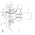
- Fig. 1 shows an emptying device 10, to which a bulk material container 50 is connected is.
- the illustration in Fig. 1 is divided vertically in the middle, wherein on the left Side the emptying device 10 and the bulk material container 50 in a closed Position are shown, while on the right side of the emptying device 10 and the bulk goods container 50 are shown in an open position.
- the emptying device 10 comprises a housing 20, in which a passage channel 22 is formed with a circular cross-section.
- the housing 20 has substantially the shape of a rectangular curved pipe section, wherein the passage channel 22nd is formed by the interior of this pipe section.
- the housing 20 has an im Essentially flat, horizontally arranged circular top, in which a circular Opening 26 is formed, which as an inlet opening 26 for inflowing into the passage 22 Bulk material (not shown) is used.
- the inlet opening 26 takes the largest Part of the surface of the housing top and opens into a first (upper) end of Passage channel 22.
- the uppermost part of the housing 20, which also provided with the inlet opening 26 Housing top comprises, is as a connection part 24 of the emptying device 10th educated.
- the connection part 24 is made of an electrically conductive material and grounded.
- an annular collar 25th formed in a horizontal plane from the inside and below Housing party projecting radially outward and for coupling the bulk goods container 50 to the emptying device 10 is used.
- the passage 22 In the connecting part 24 formed as the upper part of the passage passage 22 runs in the vertical direction. Below this, the passage 22 has a curved Part, by a rectangular bent lower portion of the tubular housing 20th is formed. After the right-angled bend or bend, the passage opens 22 in an outlet opening 23, in a vertical outer side of the housing 20th is trained. Overall, the passageway 22 extends from that in the housing top trained entrance opening 26 up to that in a vertical outside of the Housing 20 formed outlet opening 23, wherein it is in the region of the inlet opening 26 initially runs vertically downwards, in the lower region of the housing 20 at right angles turns and in the region of the outlet opening 23 extends approximately horizontally.
- a bulk material suction line (not shown) can be connected, which is connected to an evacuation device (not shown) to prevent the outflow of Bulk material out of the bulk material container 50 and through the passageway 22 therethrough by creating a vacuum in the bulk material suction line and in the passageway 22 to support.
- annular channel 28 In the top of the connecting section 24 is an upwardly open annular channel 28th (Also referred to as annular channel 28), which as compressed air outlet 28 of the emptying device 10 serves.
- the annular channel 28 extends substantially in a horizontal Plane (i.e., parallel to the top of the connecting section 24) the outer circumference of Along inlet opening 26 and surrounds them completely.
- the annular channel 28 is below and bounded on two sides by channel walls, which as parts of walls of the housing 20th are formed.
- the radially inward side wall 29 of the annular channel 28 simultaneously formed as a channel wall 29 of the passage channel 22, which this is limited to the outside in its uppermost area.
- the channel inner wall 29th the annular channel 28 is simultaneously formed as an outer wall 29 of the passage channel 22.
- the radially outer side wall of the annular channel 28 forms at the same time an outer wall of the housing 20 and its connection part 24th
- the annular channel 28 is further provided with a compressed air connection 30, which is one of includes obliquely down into the annular channel 28 opening passage through which Compressed air in the annular channel 28 can be supplied.
- a Druck Kunststoffzu111 Gustav (not shown) can be connected, which with a compressed air source (not shown) is connected to supply the annular channel 28 with compressed air.
- the thin arrows 80 in FIG. 1 show the compressed air flow 80 or its flow direction at.
- the emptying device 10 is further provided with a shutter actuating device for optionally opening and closing a closure of the bulk goods container 50 provided.
- the shutter actuating device comprises an elongate drive shaft 32, a Shutter actuating element 34 and an adjusting device 36.
- the drive shaft 32 has a circular cylindrical shape and one through the axis of the circular cylinder defined shaft axis.
- the drive shaft 32 is in one pass of a guide bushing 38 received and through the guide bush 38 in the direction of the shaft axis slidably and rotatably guided around the shaft axis.
- the passage of the Guide bushing 38 leads from below through a wall of the housing 20 in the Passage passage 22 into, wherein this wall is a part of the boundary wall of the passage channel 22 forms in the lower arcuate lot.
- the guide bushing 38 is firmly attached to this wall.
- the drive shaft 32 is in through the passage of the guide bush 38 leading arrangement arranged such that the shaft axis or their extension in the vertical direction through the center of the inlet opening 26th passes through, wherein an upper portion of the drive shaft 32 in the passageway 22 is arranged is while a lower portion of the drive shaft 32 below and outside the passageway 22 is arranged.
- the shutter actuator 34 is attached. This is essentially a cone-shaped body made of a solid material, the so mounted with its base at the top end of the drive shaft 32 is that the axis of the cone-shaped shutter actuating element 34 coaxial with Axle of the drive shaft 32 is arranged, wherein the tip of the cone, the topmost lot and the circular base of the cone is the lowest part of the shutter actuator 34 form.
- the shutter actuator 34 is made of an electric conductive material made and grounded.
- a driver ring 45 is on the outer peripheral surface of Shutter actuator 34 attached.
- the driving ring 45 is one of a made of elastic material with a comparatively large adhesion coefficient. He serves for a frictional connection between the shutter actuating element 34 and a resting on the shutter actuating element 34 closure body 60 and to take the latter by means of frictional force when the shutter actuator 34 or around its axis (that is, the axis of its cone) is moved longitudinally to this axis.
- the drive shaft 32 is coupled to the adjustment device 36 such that it by means of the adjusting device 36 either in the direction of the shaft axis with respect to the Housing 20 is vertically displaceable or adjustable up and down.
- the position with maximally downwardly shifted drive shaft 32 is used as a closed position (in Fig. 1 on the left side) and the position shifted upwards Drive shaft 32 as a fully open position (shown in Fig. 1 on the right side) the emptying device 10 and its drive shaft 32 denotes. Is the drive shaft 32 between its closed position and its fully open position arranged, this is as a partially open position of the emptying device 10th or their drive shaft 32 referred to.
- the adjusting device 36 is further formed simultaneously as a rotary drive 36, by means the drive shaft 32 with respect to the housing 20 optionally about the shaft axis is pivotable about 360 degrees back and forth.
- the adjustment device 36 is mounted on the housing 20 and completely outside the passageway 22 and below arranged by this.
- the bulk material container 50 shown in FIG. 1 is a bag 50 with a flexible container wall 53 or bag wall 53, which is made of paper and has the shape of a shell, which is closed on all sides except for the closure described below. By doing bottom, the bottom of the bag 50 forming portion of the bag wall 53 is a closure used.
- the closure has a connection flange 51, 52 a closure body 60 and a shut-off seal 65 designed as a check-seal lip.
- connection flange is made of an inner flange part 51 and an outer flange part 52 composed, both of which are annular and in the illustration of Fig. 1 are arranged such that their ring axes coincide and substantially run vertically.
- the two flange parts 51, 52 are made of an electrically conductive Material made.
- the inner flange part 51 has a circular cylinder shell-shaped part 59, which identifies the shape of a pipe section and a substantially vertical extending circular cylindrical passage 54 bounded laterally, as the outlet opening 54 for in the bag 50 recorded bulk material (not shown) is used.
- the end of the inner flange 51 is radially (i.e., horizontally) outwardly projecting Part 55 formed, which has the shape of a flat annular disc and at right angles to cylinder jacket-shaped portion 59 of the inner flange 51 is arranged.
- the outer Flange portion 52 has the shape of a thick annular disc with a central passage, the Diameter is slightly smaller than the outer diameter of the cylinder jacket-shaped Lot 59 of the inner flange portion 51 so that this cylinder jacket-shaped lot 59 under interference fit in the central passage in the annular outer flange portion 52 is plugged into it.
- annular collar 56 integrally formed in a horizontal plane from the inside and above Part of the outer flange 52 protrudes radially outward and for coupling the flange portion 52 and the bag 50 to the connection part 24 of the emptying device 10 serves.
- the bottom of the connection flange 51, 52 integrally formed collar 56 has the same outer circumference as the uppermost at the connection part 24 of the emptying device 10 molded collar 25th
- a plurality of circular compressed air passages 57, 58 are formed, which each have a diameter which is the maximum Channel width of the formed in the top of the connecting section 24 annular channel 28th equivalent.
- the compressed air passages 57, 58 lead in the vertical direction through the outer flange 52 through. They are the entire circumference of the annular outer flange portion 52 along a circular line having a diameter of the Annular channel 28 corresponding diameter (i.e., eccentric with respect to the annular outer flange portion 52) and serve as compressed air inlet 57, 58, through which compressed air can flow into the bag 50.
- the shut-off body 65 is made of a flexible, elastic plastic material and has the shape of a flat, circular disk with a central passage, the diameter of the outer diameter of the cylinder jacket-shaped portion 59 of the inner flange 51 corresponds.
- the outer diameter of the shut-off body 65 is much larger than the outer diameter of the ring-shaped portion 55 of the inner flange 51 and the outer diameter of the outer flange 52nd
- the envelope-like bag wall 53 has in its lowest area (also as the bottom of the bag 50 denotes) a circular opening whose diameter is also the outer diameter the cylinder jacket-shaped portion 59 of the inner flange 51 corresponds.
- the shut-off body 65 and the bottom of the bag 50 are superimposed Passages or openings arranged such that the cylinder jacket-shaped portion 59 of the inner flange portion 51 from top to bottom successively through the passage in the Shut-off 65, the opening in the bottom of the bag and into the central passage in the outer flange 52 are inserted.
- the bag wall 53 is in the area of Sack opening at the top of the outer flange 52 glued.
- shut-off 65 serves as shut-off and closing spring at the same time of check valves, which the compressed air passages 57, 58 to the interior of the bag 50 close and allow a compressed air flow 80 in the bag 50 in, a Compressed air and / or bulk flow in reverse direction out of the bag however, prevent.
- the radially outer region of the annular disk-shaped shut-off body 65 protrudes the outer edges of the inner flange 51 and the outer flange 52 before and protrudes into the interior of the bag 50.
- This is projecting Area of the shut-off 65 brought to vibrate (also as flutter designated). The vibrations are then applied to the interior of the bag 50 transferred bulk material and cause a loosening of the bulk material.
- the closure body 60 is for selectively closing and opening the outlet opening 54 formed and arranged. He is made of a solid, electrostatically dissipative Made of plastic and designed as a hollow, thin-walled cone, the cone shape the likewise conical interior of the closure body 60 substantially the Outer shape of the cone-shaped shutter actuating element of Emptying device 10 corresponds.
- the Closure body 60 arranged such that the axis of symmetry of the cone-shaped Closure body is vertical and is arranged coaxially to the axis of the drive shaft, the top of the cone being the topmost part and the circular one open at the bottom Base surface of the cone form the bottom part of the closure body 60.
- the maximum Diameter of the cone 60 in the area of its base is slightly smaller than that Inner diameter of the inner flange 51 formed in the outlet opening 54, see that the lowermost portion of the closure body 60 with clearance fit in the Outlet opening 54 can be arranged to close them tight, as shown in Fig. 1 is shown on the left side.
- the closure body 60 is in the vertical direction with respect to the connection flange 51, 52 can be moved downwards and upwards as well as lifted upwards from the connecting flange to To close or release the outlet opening 54 and thereby the closure to open, as shown in Fig. 1 on the right side.
- the position with maximum downwardly displaced closure body 60 is used as a closed position of the closure body 60 and the closure referred to.
- Position is the base of the closure body 60 within the outlet opening 54 arranged and closes this tight.
- the position with maximum after above shifted closure body 60 is the fully open position of the closure or of the closure body 60. Is this in Fig. 1 on the right Side shown position is the entire closure body 60 above the outlet opening 54 arranged.
- Next is the closure body 60 with respect to the connection flange 51, 52 freely rotatable about the vertical axis of symmetry of the cone.
- the connecting section 24 On the top of the connecting section 24 are further three of an elastic sealing material manufactured sealing rings 41, 42, 43 arranged so that they are in one unloaded state (i.e., when no bulk container to the emptying device 10th is coupled) at least partially from the surface plane of the top to protrude above. If - as shown in the illustration of Fig.
- connection flange 51, 52 of the bulk goods container 50 to the connection part 24 of the emptying device 10 is coupled, the sealing rings 41, 42, 43 between the abutting Surfaces of the connection flange 51, 52 and the connection part 24th compressed and then seal passages passing through these surfaces lead and through which bulk material and / or air from the bulk material container 50 into the emptying device 10 and compressed air from the emptying device 10 in the bulk material container 50 can flow into it.
- a first sealing ring 41 is arranged along the outer circumference of the annular channel 28 and seals the annular channel 28 to the outside.
- a second sealing ring 42 is the inner periphery of the annular channel 28 arranged along and seals the annular channel 28 from the inside.
- a third Sealing ring 43 is disposed along the outer circumference of the inlet opening 26 and seals the inlet opening and the passageway 22 in the top of the connection section 24 off.
- a sack 50 shown in FIG. 1 is emptied at the connecting flange 51. 52 of the bag 50 arranged cover member from the connection flange 51, 52 away. Of the Closure of the bag 50 and the shutter actuating device of the emptying device 10 are in their closed positions. Thereafter, the bag 50 together with the connecting flange 51, 52 via the housing 20 of the emptying device 10 transported. Subsequently, the coupling process for coupling the bag 50th introduced to the emptying device 10 by the bag 50 to the housing 20 down becomes.
- the closure body which is open at the bottom becomes 60 over the top over the top of the connecting portion 24 of the housing 20 protruding shutter actuator 34 is slipped, whereby the Connection flange 51, 52 together with the bag 50 with respect to the connecting section 24 and the Housing 20 centered and aligned exactly on this.
- the bag 50 is so far lowered until the connecting flange 51, 52 with its underside on top of the Housing 20 and its connection part 24 rests.
- the lowest at the connection flange 51, 52 molded collar 56 is now directly on the top of the connecting section 24 molded collar 25 on.
- the connecting flange 51, 52 by means of an annular retaining clip 47 on the connection part 24 of the emptying device 10 clamped.
- the coupling process is completed, and the bag 50 is located Now in the one shown in Fig. 1, coupled to the emptying device 10 Status.
- connecting portion 24 forms a first, the emptying device side Construction unit and provided with the collar 56 Connecting flange 51, 52 a second, bag-side construction unit of a coupling device, for the optional detachable connection of the connection flange 51, 52 is formed on the connection part 24.
- the first and second Construction unit can be coupled together in a single coupling operation or connectable to one another with the outlet opening 54 and the compressed air inlet 57, 58 provided connecting flange 51, 52 of the bag 50 to the with the inlet opening 26 and the compressed air outlet 28 provided connection part 24 of Connect emptying device 10 or couple.
- the drive shaft 32 is shifted upward. This will make it top of the drive shaft 32 mounted closure actuator 34, already in the interior the closure body 60 is arranged, from below against the closure body 60th pressed and raises this to the closure body 60 of the outlet opening 54th lift and thereby the from the connection flange 51, 52 and the closure body 60 formed closure of the bag 50 to open.
- the driving ring 45 is between the closure actuator 34 and the closure body 60 compressed and thereby ensures a non-rotatable connection acting by means of adhesion between the shutter actuator 34 and the shutter body 60.
- the shutter body 60 is by means of the shutter actuating device 32, 34, 36 to a the desired dosage of the bulk material flow corresponding height raised.
- the closure body 60 in its maximum height via the outlet opening shown. This open position of the closure has a maximum Flow of bulk material out of the sack 50 results.
- the air flow indicated by the arrows 80 is generated in the bag 50, which leads to a further loosening of the bulk material received in the bag 50 leads and also the bulk material through the outlet opening 54 through from the bag 50th
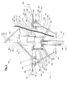
- FIG. 2 shows an emptying device 110, to which a bulk material container 150 is connected is.
- the illustration in Fig. 2 is divided vertically in the middle, wherein on the left Side the emptying device 110 and the bulk material container 150 in a closed Position are shown, while on the right side of the emptying device 110 and the bulk goods container 150 are shown in an open position.
- the bulk material container 150 or bag 150 shown in FIG. 2 differs from FIG the bulk material container 50 or bag 50 shown in FIG. 1 essentially only in FIG Reference to the formation of the closure member 160 for closing the outlet opening 154. Otherwise, the bag 150 shown in Fig. 2 is formed substantially the same as shown in Fig. 1 bag 50.
- the bag 150 shown in Fig. 2 has turn a flexible bag wall 153 and a closure provided with a two-piece connection flange 151, 152, a closure body 160 and a shut-off 165 provided is.
- the two flange parts 151, 152 are made of an electrically conductive material manufactured.
- the closure member 160 shown in FIG. 2 for closing the outlet opening 154 is a perforable sheet 160 made of a flexible sheet material, which is shown in FIG closed state on the inner flange 151 of the connecting flange 151, 152 such is welded, that they formed in the inner flange 151 Completely closes outlet opening 154.
- the through the film 160 and the Connection flange 151, 152 formed closure is only for a single opening of the Closure provided, that is, it is a one-way closure.
- the emptying device 110 shown in FIG. 2 differs from that in FIG. 1 shown emptying device 10 essentially only with respect to the training the closure actuator 132, 134, 136 for closing and optional Opening the closure of the bag 150. Otherwise, the shown in Fig. 2 Emptying device 110 substantially the same design as that shown in Fig. 1 Emptying device 10.
- the emptying device 110 shown in FIG in turn has a housing 122 provided with a passage 122, the uppermost Lot designed as a connecting portion 124 and opening into the passageway 122 with a Inlet opening 126 and a compressed air outlet 128 is provided.
- the Terminal part 124 is made of an electrically conductive material and grounded.
- the shutter actuating device 132, 134, 136 shown in FIG. 2 again comprises an elongated drive shaft 132, a shutter actuator 134 and a Adjusting device 136 for adjusting the drive shaft 132 in the direction of its longitudinal axis.
- the shutter actuator 134 is mounted on top of the drive shaft 132 and in turn formed as a cone-shaped body, wherein the tip of the cone the uppermost part and the circular base of the cone are the lowest part of the shutter actuating element 134 form.
- Closure actuating element 34 is the cone-shaped outer surface of the in FIG. 2 shown shutter actuator 134 with a plurality of sharp Cutting edges 131, 133, 135, 137 provided, which for perforating and blending serve the foil 160 of the closure of the bag 150.
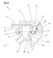
- FIG. 3 shows an emptying device 210 to which a bulk material container 250 is connected is.
- the illustration in Fig. 3 is divided vertically in the middle, with the left Side the emptying device 210 and the bulk material container 250 in a closed Position are shown, while on the right side of the emptying device 210 and the bulk goods container 250 are shown in an open position.
- the bulk goods container 250 shown in FIG. 3 is a bag-shaped bulk container 250 (also referred to as "big bag” or “bulk bag”).
- this large container 250 is in Stand alone. 5 shows the large container 250 together with another, to this identical bulk container 350 in a stacked arrangement.
- the large container 250 shown in FIGS. 3-5 differs from that in FIG Fig. 1 illustrated bag 50 in terms of its dimensions and with respect to several Hang tabs 285, 286 mounted on top of the flexible container wall 253 and allow the bulk container 250 to be hung on a hanger (e.g. Crane). Otherwise, the large container 250 shown in FIGS.
- 3-5 is essentially the same design as the bag 50 shown in FIG Large container 250 in turn has a flexible container wall 253 and a closure, the is identical to the closure of the bag 50 shown in Fig. 1 and with a two-part Connection flange 251, 252, a conical closure body 260 and a shut-off 265 is provided of a flexible material.
- the two flange parts 251, 252 are made of an electrically conductive material.
- the closure body 260 is made of a solid, electrostatic dissipative plastic.
- the emptying device 210 shown in FIG. 3 comprises a funnel-shaped housing 220, in which a passageway 222 formed with a circular cross-section is.
- the housing 220 has a substantially flat, horizontally disposed circular Top in which a circular opening 226 is formed, which serves as an inlet opening 226 for in the passage 222 incoming bulk material (not shown) is used.
- the inlet opening 226 occupies most of the surface of the housing top and opens into the upper end of the passageway 222.
- the passage channel 222 extends in the vertical direction down to an exit opening 223, wherein the diameter of the passageway 222 decreases smaller due to the funnel shape of the housing 220 downwards.
- the uppermost part of the housing 220 which also provided with the inlet opening 226 Housing top is, as a connecting portion 224 of the emptying device 210 formed.
- the connection part 224 is made of an electrically conductive material manufactured and grounded.
- an annular Collar 225 integrally formed, which projects radially outward and for coupling the Bulk container 250 to the emptying device 210 is used.
- a compressed air connection 230 to which a Druck Kunststoffzucel (not shown) connected to a compressed air source (not shown) is connected to supply the annular channel 228 with compressed air.
- the thin arrows 280 in Fig. 3 indicate the compressed air flow 280 and their flow direction.
- the emptying device 210 is further provided with a shutter actuating device for optionally opening and closing a closure of the bulk goods container 250 provided.
- the shutter actuating device comprises a shutter actuating element 234 and an adjusting device 236 provided with a piston-cylinder arrangement 270, 277, 278, a guide rod 267 and a rotary drive 237 is provided.
- the piston-cylinder arrangement 270, 277, 278 comprises a piston 270 with a circular cylindrical outer shape, by means of connecting struts 268, 269 fixed to the Housing 220 is connected and stored at this stationary.
- the piston 270 is in one circular cylindrical cavity of a first downwardly open hollow cylinder 277 such received that the first hollow cylinder 277 in the vertical direction with respect to the Piston 270 is displaceable.
- the outer shape of the piston 270 substantially corresponds the shape of the cavity of the first hollow cylinder 277.
- a first sealing ring 271 is on the circular cylinder jacket-shaped outer surface of the piston 270 along the arranged upper edge and seals the between the piston 270 and the first Hollow cylinder 277 formed gap airtight against the outside.
- a second Sealing ring 272 and a first scraper ring 273 are on the inner surface of the first Hollow cylinder 277 arranged along its lower edge. They write that between the piston 270 and the first hollow cylinder 277 formed gap below the first sealing ring 271 in addition to the outside and prevent the Ingress of bulk material or other dirt particles in this space.
- the first hollow cylinder 277 in turn has a kresizylindharide outer shape and is in a circular cylindrical cavity of a second downwardly open hollow cylinder 278 received such that the second hollow cylinder 278 in the vertical direction with respect the first hollow cylinder 277 is displaceable.
- a third sealing ring 274 is on the circular cylinder jacket-shaped outer surface of the first hollow cylinder 277 along the arranged upper edge and seals the between the first hollow cylinder 277 and the second hollow cylinder 278 formed gap airtight from the outside.
- One fourth seal ring 275 and a second scraper ring 276 are on the inner surface of the second hollow cylinder 278 along the lower edge thereof. They write that between the first hollow cylinder 277 and the second hollow cylinder 278 formed gap below the third seal ring 274 in addition to the outside and prevent The penetration of bulk material or other dirt particles in this space.
- the shutter actuator 234 is mounted, which is similar to the closure actuator shown in Fig. 1 34.
- the shutter actuating element 234 is made of an electrically conductive Material made and grounded.
- a compressed air line fed by compressed air from an external source of compressed air (not shown) (not shown) passes through the piston 270 into the space between the piston 270 and the first hollow cylinder 277. From this gap a compressed air passage leads to the space between the first hollow cylinder 277th and the second hollow cylinder 278.
- the piston 270, the first Hollow cylinder 277 and the second hollow cylinder 278 a piston-cylinder arrangement with a piston 270 mounted on the housing 220 and two with respect to the piston 270 and telescopically telescoping hollow cylinders 277, 278 created, wherein the Piston-cylinder arrangement 270, 277, 278 pneumatically by means of the compressed air source is operable to the second hollow cylinder 278 and attached to this Shutter actuator 234 in the vertical direction with respect to the housing 220 or the piston 270 to move.
- the guide rod 267 has a circular cylindrical shape and a rod axis defined by the axis of the circular cylinder which is in vertical Direction runs.
- the guide rod 267 is mounted in a fixed to the housing 220 Guide bushing 266 slidable in the vertical direction and around the rod axis rotatably guided, wherein the guide rod 267 further displaced in the vertical direction passed through passages in the piston 270 and the first hollow cylinder 277th are formed.
- the linear guide unit 266, 267 ensures that the sealing or Wiper rings 271-276 between the hollow cylinders 277, 278 and between the first Hollow cylinder 277 and the piston 270 must exert no management forces and therefore not be overburdened.
- a rotary drive 237 is further supported, by means of which the guide rod 267 and associated with this second hollow cylinder 278 with respect to the piston 270th or the housing 220, optionally about 360 degrees back and forth about the rod axis is pivotable or rotatable.
- the guide rod 267 is thus simultaneously as Drive shaft 267 is formed, by means of which the shutter actuating element 234 for Rotation about the rod axis is driven around.
- the shutter actuating element 234 shown in FIGS. 3-5 is one of one solid material produced conical hollow body, the top with its base is mounted on the second hollow cylinder 278 of the adjusting device 236 and means the adjusting device 236 displaceable in the vertical direction and about the axis of the Guide rod 267 is pivotable around back and forth.
- a pneumatic operable vibrator 239 is arranged, which the shutter actuating element 234 to vibrate or vibrate can stimulate.
- the closure body 260 sits directly on the closure actuating element 234. The vibrations generated by the vibrator are then removed by the vibrator Closure actuator 234 on the closure body 260 and from there to the transferring surrounding bulk material, thereby providing additional loosening of the bulk material is effected.
- the entire emptying device 210 shown in FIG. 3 together with the connected thereto Connecting flange 251, 252 of the large container 250 is in the vertical direction with respect to a suspension device (not shown) to which the large container 250 is suspended, movable. This will give the opportunity for continuous stretching of the large container 250 created during the emptying process to always the entire flexible bottom of the large container 250 in the direction of the outlet opening 254 out inclined to keep.
- the suspension device with respect to the emptying device 210 to be moved in the vertical direction.
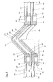
- Fig. 4 shows the large container 250 of FIG. 3 in isolation.
- the illustration in FIG. 4 is divided vertically in the middle.
- On the right side is the connection flange 251, 252 the closure of the large container 250 with a cover member 282 according to a second Variant of the invention covered.
- the cover member 281 shown in Fig. 4 on the left side is one of a fixed Material manufactured conical hollow body 281 with a bottom surface open at the bottom.
- the cone shape of the cover body 281 substantially corresponds to the cone shape At the bottom is on the cover body 281 a radially from the base the conical shape formed outwardly projecting annular disc 263, the outer circumference essentially the outer circumference of the outer flange part 252 of the connection flange 251, 252 corresponds.
- the annular disc has in the area of its outer circumference an identical outer shape as the collar 225 of the connecting portion 224 of in 3 emptying device 210.
- the cover body 281 In the state clamped to the connection flange 251, 252, the cover body 281 is partially from below through the outlet opening 254 into the cavity of the closure body 260 projecting into it, wherein the downwardly open cavity of the Cover body 281 substantially within the cavity of the closure body 260th is arranged. In this state, the cover body 281 covers the entire connection flange 251, 252 on its underside.
- the Abdeckorgan in this state 281 optionally releasably connected to the closure body 260 so that it the Closure body 260 secures mechanically and prevents the closure body 260th accidentally moved into the large container 250 and thereby the shutter unintentionally opened.
- the cover member 281 shown in Fig. 4 on the right side is one of a flexible Foil material produced covering film 282. It is the outer circumference of the connection flange along the underside of the outer flange 252 and covers the entire connecting flange 251, 252 on the underside from. In the area inside of the inner flange part 251, the cover film protrudes from below through the outlet opening 254 passes into the cavity of the closure body 260 and in turn forms a downwardly open cavity substantially within the cavity the closure body 260 is arranged.
- Fig. 5 shows the large container 250 of Figures 3 and 4 together with another identical large container 350 in a stacked arrangement, the closures the two large containers 250, 350 each with identical Abdeckorganen 281, 282; 381, 382 are covered.
- the illustration in Fig. 5 is divided vertically in the middle.
- On the left side are the connecting flanges 251, 252; 351, 352 of the closures of large containers 250; 350 with cover bodies 281, 381 according to the illustrations on the left Side of Fig. 4 covered.
- On the right side are the connecting flanges 251, 252; 351, 352 of the closures of the large containers 250; 350 with cover sheets 282, 382 according to covered on the right side of Fig. 4.
- the closure body 360 of FIG Closure of the further bulk container 350 partially in the cavity of the cover body 281 of the large container 250, wherein the ceiling part of the flexible container wall 353 of the further large container 350 resting on its closure body 360 between this closure body 360 and the covering body 281 of the other Large container 250 is arranged.
- the closure body 360 of the closure of the other large container 350 partially in the received cavity formed by the cover sheet 282 of the large container 250, the ceiling part of the flexible container wall of the further large container 350 its closure body 360 resting between this closure body 360 and the Covering film 282 of the other large container 250 is arranged.
- FIG. 6 shows an emptying device 310, to which the one already shown in FIG. 1 shown bulk goods container 50 of FIG. 1 is connected.
- FIG. 6 shows the emptying device 310 and the bulk goods container 50 or the bag 50 shown in a closed position.
- the emptying device 310 shown in FIG. 6 differs from that in FIG. 1 shown emptying device 10 essentially only with respect to the training the connection part, to which the connection flange 51, 52 of the bag 50th can be connected or connected. Otherwise, the illustrated in Fig. 6 Emptying device 310 substantially the same design as that shown in Fig. 1 Emptying device 10.
- the emptying device 310 shown in FIG. 6 again has one with a Through passage provided housing 320.
- Emptying device 10 is the connecting part of the shown in Fig. 6
- Emptying device 310 is not formed as the uppermost part of the housing 320.
- the connection section is part of a substantially annular Component 321 formed whose inner diameter of the inner diameter of the Passage channel at the top of the housing 320 corresponds.
- the annular member 321 is part a buildable to the housing 320 or attached kit.
- the annular Component 321 is fastened to the housing 320 at the top by means of screws (not shown) or grown on this housing 320.
- annular member 321 In the top of the annular member 321 are opening into the passageway Inlet opening and a ring-shaped compressed air outlet 328 is formed, which in their shapes and dimensions substantially the corresponding inlet opening 26th or the corresponding compressed air outlet 28 of FIG. 1 Emptying device 10 correspond. Further, the annular member 321 is provided with a Compressed air connection 330 provided, the one from obliquely down into the compressed air outlet 328 Comprises opening passage through which compressed air in the compressed air outlet 328 can be supplied.
- connection flange 51, 52 of the bag 50 is the second by means of an annular retaining clip 347 on the connection part or of the component 321 and the emptying device 10 clamped.
- annular retaining clip 347 on the connection part or of the component 321 and the emptying device 10 clamped.
- the emptying device 310 shown in FIG. 6 in turn comprises one with a cone-shaped shutter actuator 334 provided shutter actuating device.
- a driving ring Mounted 345 which serves a frictional connection between the shutter actuating element 334 and on the shutter actuator 334 to provide resting closure body 60 and the latter by means of friction force take.
- the invention provides a bulk material emptying device and a bulk container to be specified, which is a tight connection the bulk goods container to the emptying device and a reliable emptying of bulk materials from the bulk material container.
Landscapes
- Engineering & Computer Science (AREA)
- Mechanical Engineering (AREA)
- Control And Other Processes For Unpacking Of Materials (AREA)
- Filling Or Emptying Of Bunkers, Hoppers, And Tanks (AREA)
- Centrifugal Separators (AREA)
Abstract
Description
Die Erfindung betrifft eine Entleerungsvorrichtung zum Entleeren von Schüttgut aus einem Schüttgutbehälter sowie einen Schüttgutbehälter und einen Verschluss für einen Schüttgutbehälter. The invention relates to an emptying device for emptying bulk material from a Bulk container and a bulk material container and a closure for a bulk material container.
Zum Entleeren bzw. Auslassen von Schüttgütern aus Schüttgutbehältern werden die Schüttgüter durch in den Behälterwänden ausgebildete Austrittsöffnungen hindurch ausgetragen. Dazu werden die Schüttgutbehälter typischerweise an eine Entleerungsvorrichtung (auch als Auslass- oder Andockvorrichtung bzw. Auslass- oder Andockstation bezeichnet) angeschlossen, die mit einer Eintrittsöffnung versehen ist, welche in einen Durchlasskanal mündet, durch welchen hindurch das Schüttgut ausströmen (auch als ausfliessen bezeichnet) kann.For emptying or discharging bulk goods from bulk containers, the Bulk solids discharged through trained in the container walls outlet openings. For this purpose, the bulk containers are typically to an emptying device (also referred to as outlet or docking device or outlet or docking station) connected, which is provided with an inlet opening, which in a passageway opens, through which the bulk material flows (also called outflow) can.
Aus der Druckschrift EP 0 915 032 ist eine Schüttgut-Entleerungsvorrichtung bekannt, die ein mit einer Eintrittsöffnung versehenes Anschlussgehäuse aufweist, das mit einem Durchlasskanal versehen ist. Ein mit einer Austrittsöffnung versehener Schüttgutbehälter ist derart dicht an das Anschlussgehäuse anschliessbar, dass das Schüttgut bei geöffneter Austrittsöffnung aus dem Schüttgutbehälter heraus durch den Durchlasskanal hindurch ausströmen kann.From the document EP 0 915 032 a bulk material emptying device is known which a provided with an inlet connection housing, which with a Passage channel is provided. A provided with an outlet bulk container is so tightly connected to the connection housing that the bulk material when opened Outlet opening out of the bulk material container through the passage channel can flow out.
Der Schüttgutbehälter ist zwar vergleichsweise dicht an die in der Druckschrift EP 0 915 032 beschriebene Entleerungsvorrichtung anschliessbar. Hingegen können bei Schüttgütern, die zum Verklumpen neigen, Probleme beim Entleeren entstehen, indem die Verklumpungen im Schüttgutbehälter den Entleerungsvorgang behindern oder sogar vollständig blockieren.The bulk material container is indeed comparatively close to those in the document EP 0 915 032 described emptying device connected. On the other hand, at Bulk goods that tend to clump, problems arise during emptying, by the Clumping in the bulk material container hampers the emptying process or even completely block.
In der Druckschrift US 5,474,111 wird eine Schüttgut-Entleerungsvorrichtung beschrieben, die eine spitze Lanze umfasst. Zum Entleeren eines sackförmigen Schüttgutbehälters wird die hohle Lanze durch die Behälterwandung hindurch gestochen, worauf das Schüttgut durch mehrere Eintrittsöffnungen hindurch in einen in der Lanze ausgebildeten Durchlasskanal und durch diesen hindurch aus dem Schüttgutbehälter hinaus strömt. Die Lanze ist weiter mit einer Düse versehen, durch welche hindurch Druckluft in den Schüttgutbehälter hinein geblasen werden kann, um das Ausströmen des Schüttguts zu unterstützen.The document US Pat. No. 5,474,111 describes a bulk material emptying device, which includes a pointed lance. To empty a sack-shaped bulk container is the hollow lance pierced through the container wall, whereupon the bulk material through a plurality of inlet openings into a passage formed in the lance and flows out of it through the bulk material container. The lance is further provided with a nozzle, through which compressed air in the bulk material container can be blown into it to support the flow of bulk material.
Im Falle von feinkörnigem Schüttgut bietet die in der Druckschrift US 5,474,111 beschriebene Entleerungsvorrichtung Probleme hinsichtlich eines genügend dichten Anschlusses der Entleerungslanze an den Schüttgutbehälter. Es besteht die Gefahr, dass Schüttgut an der Lanze vorbei aus der durch die Lanze geschaffenen Perforation aus dem Schüttgutbehälter heraus strömt und verloren geht.In the case of fine-grained bulk material, that described in US Pat. No. 5,474,111 Emptying device Problems with a sufficiently tight connection the emptying lance to the bulk material container. There is a risk that bulk goods the lance over from the created by the lance perforation from the bulk material container flows out and gets lost.
Aufgabe der Erfindung ist es, eine dem eingangs genannten technischen Gebiet zugehörende Entleerungsvorrichtung und einen Schüttgutbehälter anzugeben, welche einen dichten Anschluss des Schüttgutbehälters an die Entleerungsvorrichtung sowie ein zuverlässiges Entleeren und Wegfördern von Schüttgütern aus dem Schüttgutbehälter ermöglichen.The object of the invention is a belonging to the aforementioned technical field Specify emptying device and a bulk material container, which dense Connection of the bulk material container to the emptying device and a reliable Allow emptying and removal of bulk materials from the bulk material container.
Die Lösung der Aufgabe ist durch die Merkmale der unabhängigen Patentansprüche definiert. Gemäss der Erfindung weist eine Entleerungsvorrichtung zum Entleeren von Schüttgut aus einem Schüttgutbehälter eine Basisstruktur auf und eine mit einer Eintrittsöffnung versehene Anschlusspartie auf und einen Durchlasskanal, in den die Eintrittsöffnung mündet. Der Schüttgutbehälter hat einen Verschluss mit einem Anschlussflansch und einem Verschlussorgan. Der Anschlussflansch ist mit einer Austrittsöffnung für im Schüttgutbehälter aufgenommenes Schüttgut versehen, durch welche hindurch das Schüttgut bei offener Austrittsöffnung ausströmen kann. Das Verschlussorgan ist zum Verschliessen und wahlweisen Öffnen der Austrittsöffnung ausgebildet und angeordnet. Der Anschlussflansch des Schüttgutbehälters ist derart dicht an die Anschlusspartie der Entleerungsvorrichtung anschliessbar, dass - wenn der Anschlussflansch an die Anschlusspartie angeschlossen ist, d. h. in einem an die Entleerungsvorrichtung angeschlossenen Zustand des Schüttgutbehälters bzw. seines Anschlussflansches - bei geöffnetem Verschluss Schüttgut durch die Austrittsöffnung hindurch aus dem Schüttgutbehälter heraus, durch die Eintrittsöffnung hindurch in den Durchlasskanal hinein und anschliessend durch den Durchlasskanal hindurch strömen (auch als fliessen bezeichnet) kann. Die Entleerungsvorrichtung weist weiter eine an der Basisstruktur oder an der Anschlusspartie gelagerte Verschlussbetätigungsvorrichtung auf, die für eine Betätigung des Verschlusses des Schüttgutbehälters ausgebildet ist. Die Verschlussbetätigungsvorrichtung ist mit einem Verschlussbetätigungselement und einer Verstellvorrichtung versehen. Die Verstellvorrichtung ist derart ausgebildet und angeordnet, dass in einem an die Anschlusspartie angeschlossenen Zustand des Verschlusses das Verschlussbetätigungselement mittels der Verstellvorrichtung wahlweise zwischen einer Schliessstellung und wenigstens einer Offenstellung bezüglich der Anschlusspartie verschiebbar ist.The solution of the problem is defined by the features of the independent claims. According to the invention, an emptying device for emptying bulk material from a bulk material container, a basic structure and one with an inlet opening provided connecting part on and a passage in which the inlet opening empties. The bulk material container has a closure with a connection flange and a closure member. The connection flange is provided with an outlet opening for the Bulk container provided bulk material, through which the Bulk material can flow out when the outlet opening is open. The closure member is for Closing and optionally opening the outlet opening formed and arranged. The connection flange of the bulk goods container is so close to the connection part of the Emptying device connectable, that - if the connection flange to the Connecting part is connected, d. H. in one to the emptying device connected state of the bulk goods container or its connecting flange - at open closure bulk material through the outlet opening out of the Bulk container out, through the inlet opening into the passageway inside and then flow through the passageway (also as a flow can). The emptying device further has one on the base structure or on the connection part mounted on shutter actuating device, which for a Actuation of the closure of the bulk goods container is formed. The A shutter actuator is provided with a shutter actuator and a shutter actuator Adjustment provided. The adjusting device is designed and arranged in such a way in a state of the closure connected to the connection part, the Closure actuating element by means of the adjusting device optionally between a Closing position and at least one open position with respect to the connection section is displaceable.
Die Anschlusspartie ist weiter mit einem Pneumatikgasauslass versehen, und an einer Aussenseite des Anschlussflansches des Schüttgutbehälters ist ein dem Pneumatikgasauslass entsprechender Pneumatikgaseinlass des Schüttgutbehälters angeordnet (wobei hier aussen in Bezug auf den Schüttgutbehälter zu verstehen ist und wobei die Aussenseite des Anschlussflansches einen Teil der Aussenseite des Schüttgutbehälters bildet). Der an der Aussenseite des Schüttgutbehälters bzw. dessen Anschlussflansches angeordnete Pneumatikgaseinlass ist derart an den Pneumatikgasauslass der Anschlusspartie der Entleerungsvorrichtung anschliessbar, dass Pneumatikgas von der Entleerungsvorrichtung durch den Pneumatikgasauslass der Anschlusspartie und den Pneumatikgaseinlass des Anschlussflansches hindurch in den Schüttgutbehälter hinein strömen kann, um eine Auflockerung des im Schüttgutbehälter aufgenommenen Schüttguts zu bewirken und dadurch das Ausströmen des Schüttguts zu unterstützen.The connection section is further provided with a pneumatic gas outlet, and on an outside the connecting flange of the bulk goods container is a pneumatic gas outlet corresponding pneumatic gas inlet of the bulk goods container arranged (here outside with respect to the bulk goods container and the outside of the Connecting flange forms part of the outside of the bulk goods container). The at the Outside of the bulk goods container or its connecting flange arranged pneumatic gas inlet is so to the pneumatic gas outlet of the connection part of the emptying device connectable that pneumatic gas from the emptying device through the pneumatic gas outlet of the connection section and the pneumatic gas inlet of the connection flange can flow through into the bulk material container to a loosening cause of the bulk material container received bulk material and thereby to support the outflow of the bulk material.
Unter einem Pneumatikgas wird irgend ein für pneumatische Anwendungen geeignetes gasförmiges Strömungsmittel (Gasmedium) verstanden. Pneumatikgas kann z. B. Luft sein, insbesondere Luft, die einen gegenüber dem Luftdruck der Umgebungsluft erhöhten Druck aufweist (üblicherweise als Druckluft bezeichnet). Pneumatikgas kann aber auch Stickstoff, Edelgas oder irgend ein anderes für Pneumatikanwendungen geeignetes Gas oder Gasgemisch sein.Under a pneumatic gas is any suitable for pneumatic applications gaseous fluid (gas medium) understood. Pneumatic gas can z. Air, in particular air, the one compared to the air pressure of the ambient air increased pressure has (usually referred to as compressed air). Pneumatic gas can as well Nitrogen, inert gas, or any other gas suitable for pneumatic applications or gas mixture.
Im Zusammenhang mit der vorliegenden Beschreibung und den Ansprüchen bedeutet ein an die Anschlusspartie der Entleerungsvorrichtung anschliessbarer Anschlussflansch des Schüttgutbehälters, dass der Anschlussflansch und die Anschlusspartie derart ausgebildet sind, dass sie in schüttgutleitender Funktion aneinander anschliessbar bzw. miteinander verbindbar sind. Dabei können der Schüttgutbehälter verfahrbar oder verschiebbar und die Entleerungsstation stationär sein, um das Anschliessen zu ermöglichen. Es können aber auch der Schüttgutbehälter stationär und die Entleerungsstation verfahr- oder verschiebbar sein, oder es können sowohl der Schüttgutbehälter als auch die Entleerungsstation verfahr- oder verschiebbar sein, um das Anschliessen zu ermöglichen. In analoger Weise bedeutet ein an den Pneumatikgasauslass der Entleerungsvorrichtung (bzw. deren Anschlusspartie) anschliessbarer Pneumatikgaseinlass des Schüttgutbehälters (bzw. dessen Anschlussflansches), dass der Pneumatikgaseinlass und der Pneumatikgasauslass in pneumatikgasleitender Funktion aneinander anschliessbar bzw. miteinander verbindbar sind, wobei wiederum der Schüttgutbehälter und/oder die Entleerungsvorrichtung verfahr- bzw. verschiebbar sein können, um das Anschliessen zu ermöglichen.In the context of the present specification and claims, means to the connection section of the emptying device connectable connection flange of the Bulk container, that the connecting flange and the connecting part formed in such a way are that they can be connected together in bulk material conducting function or with each other are connectable. The bulk material container can be moved or moved and the Emptying station be stationary to allow the connection. But it can also the bulk material container stationary and the emptying station movable or displaceable be, or it may be both the bulk container and the emptying station be moved or displaced to allow the connection. In an analogous way means a to the pneumatic gas outlet of the emptying device (or its connection section) connectable pneumatic gas inlet of the bulk material container (or its Connecting flange), that the pneumatic gas inlet and the pneumatic gas outlet in Pneumatikgasleitender function connected to each other or connectable are, in turn, the bulk material container and / or the emptying device traversed or can be displaced to allow the connection.
Die Basisstruktur kann als Gestell oder als Gehäuse der Entleerungsvorrichtung ausgebildet sein. Die Anschlusspartie kann als integraler Teil der Basisstruktur ausgebildet sein. Der Durchlasskanal kann ebenfalls als integraler Teil der Basisstruktur ausgebildet sein. Er kann aber auch in einem eigenständigen Bauteil ausgebildet sein, das an der Basisstruktur der Entleerungsvorrichtung angeordnet ist.The base structure can be used as a frame or as a housing of the emptying device be educated. The connection part can be formed as an integral part of the basic structure be. The passageway may also be formed as an integral part of the base structure be. But it can also be formed in an independent component that at the Basic structure of the emptying device is arranged.
Der Schüttgutbehälter kann flexible Behälterwände aufweisen und z. B. als Sack oder als Grossbehälter (auch als "big bag" oder "bulk bag" bezeichnet) ausgebildet sein. Der Schüttgutbehälter kann aber auch feste Behälterwände aufweisen und z. B. als Fass oder Container ausgebildet sein.The bulk material container may have flexible container walls and z. B. as a sack or as Large container (also referred to as "big bag" or "bulk bag") may be formed. Of the But bulk containers can also have solid container walls and z. B. as barrel or Container be formed.
Unter einer geöffneten oder offenen Austrittsöffnung wird die Austrittsöffnung bei geöffnetem resp. offenem Verschluss verstanden. Der Verschluss befindet sich dann in einer Offenstellung.Under an open or open outlet opening, the outlet opening is open respectively. understood open closure. The closure is then in one Open position.
Die Verschlussbetätigungsvorrichtung kann direkt an der Anschlusspartie der Entleerungsvorrichtung gelagert sein. Die Verschlussbetätigungsvorrichtung kann aber auch an der Basisstruktur der Entleerungsvorrichtung gelagert sein.The closure actuating device can directly on the connection part of the emptying device be stored. The shutter actuator can also on the base structure of the emptying device to be stored.
Das Verschlussorgan kann ein fester Körper (d. h. ein Verschlusskörper) sein, und die Verschlussbetätigungsvorrichtung kann zum wahlweisen Öffnen und wieder Verschliessen des Verschlusses ausgebildet sein, um ein dosierbares Auslassen von Schüttgut aus dem Schüttgutbehälter zu ermöglichen. Der aus einem festen Material (z. B. Metall oder Kunststoff) gefertigte Verschlusskörper kann insbesondere konusförmig ausgebildet sein, was sich als besonders vorteilhaft für ein dosierbares Entleeren von Schüttgut erwiesen hat. The closure member may be a solid body (i.e., a closure body) and the shutter actuator can be used to selectively open and close the Closure be formed to a metered discharge of bulk material from the To allow bulk containers. Made of a solid material (eg metal or plastic) manufactured closure body may be formed in particular cone-shaped, which has proven to be particularly advantageous for a metered emptying of bulk material.
Das Verschlussorgan kann aber auch lediglich eine perforierbare Partie der Behälterwand, eine perforierbare Folie oder ein anderes perforierbares Verschlusselement sein. In diesem Falle ist der Verschluss bloss für ein einmaliges Öffnen vorgesehen, d. h., es ist ein Einwegverschluss.But the closure member may also only a perforable batch of the container wall, a perforable film or other perforable closure element. In this Trap, the closure is intended only for a single opening, d. h., it is a one-way closure.
Das Verschlussorgan kann im Wesentlichen in einem zur Aufnahme des Schüttguts vorgesehenen Innenraum des Schüttgutbehälters angeordnet sein, wobei es insbesondere in seiner Schliessstellung eine Partie der Behälterwandung des Schüttgutbehälters bilden kann.The closure member may substantially in a provided for receiving the bulk material Interior of the bulk goods container, it being in particular in form its closed position a lot of the container wall of the bulk material container can.
Es wird eine Pneumatikgaszufuhr durch den Pneumatikgasauslass der Entleerungsvorrichtung und den Pneumatikgaseinlass des Schüttgutbehälters hindurch bereit gestellt. Für den Anschluss des Pneumatikgaseinlasses des Schüttgutbehälters an den Pneumatikgasauslass der Entleerungsvorrichtung können bekannte Pneumatikkupplungen verwendet werden, wobei manuell und/oder automatisch betätigbare Kupplungen möglich sind. Die Pneumatikgaszufuhr durch den Pneumatikgasauslass der Entleerungsvorrichtung und den Pneumatikgaseinlass des Schüttgutbehälters hindurch schafft die Möglichkeit, allfällig verklumptes Schüttgut im Schüttgutbehälter oder Schüttgutbrücken, die sich z.B. während der Lagerung oder dem Transport im Schüttgut gebildet haben, mittels Pneumatikgasstössen aufzulockern. Ein solcher Auflockerungsvorgang wird auch als Fluidisierung des Schüttguts bezeichnet. Durch die Möglichkeit zur Fluidisierung des Schüttguts mittels Pneumatikgasstössen kann insbesondere im Falle von Schüttgütern, die zu einer Verklumpung oder Brückenbildung neigen, die Gefahr einer Blockierung des Entleerungsvorgangs wesentlich vermindert und somit die Zuverlässigkeit des Entleerungsvorgangs verbessert werden.There is a pneumatic gas supply through the pneumatic gas outlet of the emptying device and the pneumatic gas inlet of the bulk goods container provided therethrough. For the connection of the pneumatic gas inlet of the bulk goods container to the pneumatic gas outlet The emptying device can use known pneumatic clutches be, with manually and / or automatically operable couplings are possible. The Pneumatic gas supply through the pneumatic gas outlet of the emptying device and the Pneumatic gas inlet of the bulk material container creates the possibility of any clumping Bulk goods in the bulk material container or bulk goods bridges, which are e.g. while have formed the storage or transport in bulk material, by means of pneumatic gas sockets loosen. Such a loosening process is also called fluidization of the Schüttguts called. Due to the possibility of fluidization of the bulk material by means of Pneumatikgasstössen can in particular in the case of bulk goods, which leads to a Clumping or bridging tend to be a danger of blocking the emptying process significantly reduced and thus the reliability of the emptying process be improved.
Zudem kann durch das Einblasen von Pneumatikgas eine vollständige, weitgehend rückstandsfreie Entleerung des Schüttgutbehälters erreicht werden, was mit bisher bekannten Entleerungsvorrichtungen insbesondere bei der Verwendung von Schüttgutbehältern mit flexiblen Behälterwänden (z.B. Säcken) meistens nicht möglich war.In addition, the injection of pneumatic gas, a complete, largely residue-free Emptying of the bulk goods container can be achieved, what with previously known Emptying devices, especially when using bulk containers with flexible container walls (e.g., bags) was mostly not possible.
Die Entleerungsvorrichtung kann weiter eine Steuerungseinheit zur Steuerung der Pneumatikgaszufuhr zum Pneumatikgasauslass umfassen, so dass das Pneumatikgas mittels dieser Steuerungseinheit gesteuert in den Schüttgutbehälter eingeblasen werden kann. Die Steuerungseinheit kann zur Steuerung der Pneumatikgaszufuhr in Abhängigkeit des Schüttgutmaterials, des Füllstands im Schüttgutbehälter und/oder der Evakuierleistung einer an den Durchlasskanal angeschlossenen Evakuiervorrichtung ausgebildet sein.The emptying device may further comprise a control unit for controlling the Pneumatic gas supply to the pneumatic gas outlet include, so that the pneumatic gas controlled by this control unit are injected into the bulk material container can. The control unit can be used to control the pneumatic gas supply depending the bulk material, the level in the bulk material container and / or the Evacuation of a device connected to the passage evacuation device be educated.
Indem der Schüttgutbehälter mit einem spezifisch der Anschlusspartie der Entleerungsvorrichtung entsprechenden Anschlussflansch versehen ist, wird ein dichter Anschluss des Schüttgutbehälters an die Entleerungsvorrichtung gewährleistet. Dadurch wird verhindert, dass Schüttgut durch die Austrittsöffnung hinaus am Durchlasskanal vorbei strömt und verloren geht.By the bulk goods container with a specifically the connection part of the emptying device is provided with a corresponding connection flange, a tight connection of Bulk container ensures the emptying device. This prevents that bulk material flows through the outlet opening past the passage channel and get lost.
Die Anordnung des Pneumatikgaseinlasses an einer Aussenseite des Schüttgutbehälters bzw. seines Anschlussflansches erweist sich darüber hinaus als vorteilhaft, weil dadurch eine Verunreinigung des Pneumatikgasauslasses der Entleerungsvorrichtung und der gesamten Anschlusspartie der Entleerungsvorrichtung durch das Schüttgut weitgehend vermieden werden kann. Dieser Vorteil ist insbesondere im Falle von Schüttgütern von Bedeutung, für die erhöhte Anforderungen hinsichtlich der Reinheit (z.B. bei Arzneimitteln) oder der Sicherheit (bei toxischen Schüttgütern) einzuhalten sind. Im Gegensatz zur erfindungsgemässen Entleerungsvorrichtung ist die in den Innenraum des Schüttgutbehälters eingeführte Lanzenspitze der in der Druckschrift US 5,474,111 beschriebenen Entleerungsvorrichtung einer starken Verunreinigung durch das Schüttgut ausgesetzt. Dadurch ist jedesmal eine aufwändige Reinigung der Entleerungsvorrichtung erforderlich, wenn diese nach dem Entleeren eines ersten Schüttgutbehälters entfernt wird und auch wenn diese erneut zum Entleeren eines weiteren Schüttgutbehälters verwendet werden soll.The arrangement of the pneumatic gas inlet on an outside of the bulk goods container or its connection flange proves to be moreover advantageous because thereby contamination of the pneumatic gas outlet of the emptying device and the whole Connecting part of the emptying device by the bulk material largely can be avoided. This advantage is particularly true in the case of bulk materials of Importance for which increased purity requirements (for example in the case of pharmaceuticals) or safety (for toxic bulk materials). In contrast to the invention Emptying device is in the interior of the bulk goods container introduced lance tip of the emptying device described in the document US 5,474,111 exposed to heavy contamination by the bulk material. Thereby Every time an elaborate cleaning of the emptying device is required when this is removed after emptying a first bulk container and even if this is to be used again for emptying another bulk goods container.
Der Pneumatikgasauslass an der Anschlusspartie der Entleerungsvorrichtung kann weiter in vorteilhafter Weise für eine zusätzliche Reinigung der Anschlusspartie der Entleerungsvorrichtung und/oder des Verschlusses des Schüttgutbehälters verwendet werden. Nach der Beendigung des Entleerungsvorgangs und insbesondere sogar nach einem Loslösen des Anschlussflansches von der Anschlusspartie kann nämlich nochmals Pneumatikgas durch den Pneumatikgasauslass hindurch ausgeblasen werden, um mittels der so erzeugten Pneumatikgasströmung allfällig noch an der Anschlusspartie und/oder am Anschlussflansch vorhandenes Schüttgut wegzublasen. Falls an den Durchlasskanal eine Evakuiervorrichtung angeschlossen ist, kann das weggeblasene Schüttgut gleich mittels der Evakuiervorrichtung durch die Eintrittsöffnung und den Durchlasskanal hindurch abgesaugt werden.The pneumatic gas outlet on the connection part of the emptying device can continue advantageously for additional cleaning of the connection part of the emptying device and / or the closure of the bulk goods container. To the completion of the emptying process and in particular even after a detachment namely the connection flange of the connection section can again pneumatic air are blown out through the pneumatic gas outlet so as to be generated by the thus generated Pneumatic gas flow possibly still on the connection section and / or on the connection flange Blow away existing bulk material. If the passageway a Evacuation device is connected, the blown bulk can equal by means of the evacuation device through the inlet opening and the passage channel therethrough be sucked off.
Im Falle eines Schüttgutbehälters mit flexiblen Behälterwänden (z. B. eines Schüttgutbehälters in Form eines Sacks) kann mittels der Verschlussbetätigungsvorrichtung ein weiterer Vorteil erreicht werden. Die Decke des Schüttgutbehälters kann dann nämlich zumindest in einer späten Phase des Entleerungsvorgangs durch das mittels der Verstellvorrichtung nach oben (z.B. in eine Offenstellung) verschobene Verschlussbetätigungselement gestützt werden, um zu verhindern, dass - wenn der Schüttgutbehälter nahezu leer ist - die flexible Schüttgutbehälterdecke auf den Schüttgutbehälterboden und/oder auf die Austrittsöffnung zu liegen kommt und dadurch eine vollständige Entleerung des Schüttgutbehälters behindert. Im Falle eines Verschlussorgans, das ein aus einem festen Material gefertigter Verschlusskörper ist, kann das Verschlussbetätigungselement diesen Verschlusskörper stützen. Die Decke des nahezu leeren Schüttgutbehälters kann dann auf dem Verschlusskörper aufliegen und durch diesen gestützt werden, welcher seinerseits durch das Verschlussbetätigungselement gestützt wird, so dass die Decke indirekt wiederum durch das Verschlussbetätigungselement gestützt wird. Im Falle eines Verschlussorgans, das lediglich aus einer einmal verwendbaren Folie besteht, kann die Schüttgutbehälterdecke auch direkt mittels dem Verschlussbetätigungselement gestützt werden. Durch das direkte oder indirekte Stützen der Schüttgutbehälterdecke mittels dem Verschlussbetätigungselement kann selbst im Falle eines mit flexiblen Behälterwänden versehenen Schüttgutbehälters, der während dem Entleerungsvorgang nirgends aufgehängt ist, eine vollständige, rückstandsfreie Entleerung des Schüttgutbehälters erreicht werden.In the case of a bulk goods container with flexible container walls (eg a bulk goods container in the form of a bag) can by means of the shutter actuating device another Advantage can be achieved. The ceiling of the bulk goods container can then at least in a late stage of the emptying process by means of the adjusting device upwardly (e.g., in an open position) displaced shutter actuator be supported to prevent - when the bulk container is almost empty - the flexible bulk material container cover on the bulk material container bottom and / or on the Outlet opening comes to rest and thus a complete emptying of the bulk material container with special needs. In the case of a closure member, the one made of a solid material manufactured closure body, the closure actuating element can this closure body support. The ceiling of the nearly empty bulk container can then open rest on the closure body and be supported by this, which in turn is supported by the shutter actuator, so that the ceiling in turn indirectly is supported by the shutter actuator. In the case of a closing organ, which consists only of a single-use film, the bulk container cover also be supported directly by the shutter actuator. By the direct or indirect support of the bulk material container cover by means of the closure actuating element can even in the case of having flexible container walls Bulk container, which is nowhere suspended during the emptying process, a complete, residue-free emptying of the bulk material container can be achieved.
Gemäss einer bevorzugten Alternative zu einer als integraler Teil der Basisstruktur ausgebildete Anschlusspartie ist die mit einem Pneumatikgasauslass versehene Anschlusspartie als Bestandteil eines Bausatzes ausgebildet, der an die Basisstruktur der Entleerungsvorrichtung anbaubar oder angebaut ist. In einem betriebsbereiten Zustand der Entleerungvorrichtung ist dieser Bausatz fest an der Basisstruktur angebaut bzw. mit dieser verbunden. Mittels eines solchen Bausatzes wird die Möglichkeit geschaffen, eine bestehende Entleerungsvorrichtung, die nicht mit einem Pneumatikgasauslass versehen ist, auf einfache und kostengünstige Art mit einem Pneumatikgasauslass nachzurüsten.According to a preferred alternative to one as an integral part of the basic structure Trained connecting section is provided with a pneumatic gas outlet Anschlusspartie formed as part of a kit, which corresponds to the basic structure of the Emptying device is attachable or grown. In an operational state of Emptying device, this kit is firmly attached to the base structure or with this connected. By means of such a kit, the possibility is created, a existing emptying device that does not provide a pneumatic gas outlet is to retrofit in a simple and inexpensive way with a pneumatic gas outlet.
Gemäss einer bevorzugten Ausführungsart der Erfindung ist die mit der Eintrittsöffnung und dem Pneumatikgasauslass versehene Anschlusspartie als erste, entleerungsvorrichtungsseitige Konstruktionseinheit einer gemeinsamen Kupplungsvorrichtung für das wahlweise wieder lösbare Anschliessen (d. h. das wahlweise wieder lösbare Kuppeln) sowohl des Anschlussflansches an die Anschlusspartie als auch des Pneumatikgaseinlasses an den Pneumatikgasauslass ausgebildet. Die Kupplungsvorrichtung umfasst eine zweite, schüttgutbehälterseitige Konstruktionseinheit, die durch den Anschlussflansch gebildet ist. Die erste und zweite Konstruktionseinheit sind in einem einzigen Kupplungsvorgang miteinander kuppelbar bzw. aneinander anschliessbar, um den Anschlussflansch des Schüttgutbehälters an die Anschlusspartie der Entleerungsvorrichtung und den Pneumatikgaseinlass des Schüttgutbehälters an den Pneumatikgasauslass der Entleerungsvorrichtung anzuschliessen bzw. anzukuppeln. Dabei kann die Kupplungsvorrichtung mechanisch, pneumatisch oder hydraulisch betätigbar sein, um den Kupplungsvorgang durchzuführen. Die Kupplungsvorrichtung ist vorzugsweise zum wahlweise wieder lösbaren Anschliessen bzw. Ankuppeln der beiden Konstruktionseinheiten aneinander ausgebildet, wobei die Kupplungsvorrichtung z. B. als sogenannte Bajonett-Kupplung ausgebildet sein kann. Mittels dieser gemeinsamen Kupplungsvorrichtung kann einerseits ein Entleerungs- oder Auslasspfad zum Entleeren (auch als Auslassen bezeichnet) des Schüttguts aus dem Schüttgutbehälter und andererseits eine Pneumatikgasleitung zur Versorgung des Schüttgutbehälters mit Pneumatikgas geschaffen werden. Die gleiche Konstruktionseinheit dient somit sowohl zur Kupplung des Pneumatikgaseinlasses des Schüttgutbehälters an den Pneumatikgasauslass der Entleerungsvorrichtung als auch zur Kupplung des Anschlussflansches des Schüttgutbehälters an die Anschlusspartie der Entleerungsvorrichtung derart, dass Schüttgut durch die Austrittsöffnung aus dem Schüttgutbehälter heraus und durch die Eintrittsöffnung in den Durchlasskanal der Entleerungsvorrichtung hinein strömt.According to a preferred embodiment of the invention, the one with the inlet opening and the pneumatic gas outlet port provided as the first, the emptying device side Construction unit of a common coupling device for the optionally detachable connection (ie the optionally detachable coupling) both the connection flange to the connection section and the pneumatic gas inlet formed on the pneumatic gas outlet. The coupling device comprises a second, bulk container-side construction unit, through the connecting flange is formed. The first and second construction units are in a single coupling operation can be coupled together or connected to one another to the connection flange of the bulk goods container to the connection part of the emptying device and the Pneumatic gas inlet of the bulk material container to the pneumatic gas outlet of the emptying device connect or couple. In this case, the coupling device be mechanically, pneumatically or hydraulically actuated to the coupling process perform. The coupling device is preferably for releasable again Connecting or coupling the two construction units formed together, wherein the coupling device z. B. be designed as a so-called bayonet coupling can. By means of this common coupling device, on the one hand, an evacuation or discharge path for emptying (also referred to as omission) of the bulk material from the Bulk container and on the other hand, a pneumatic gas line to supply the Bulk containers are created with pneumatic gas. The same construction unit thus serves both for coupling the pneumatic gas inlet of the bulk goods container the pneumatic gas outlet of the emptying device as well as for coupling the Connecting flange of the bulk goods container to the connecting section of the Emptying device such that bulk material through the outlet opening of the Bulk container out and through the inlet opening in the passage of the Emptying device flows into it.
Als Alternative zu einer gemeinsamen Kupplung können jedoch auch separate Kupplungen für die Schaffung eines Schüttgut-Auslasspfades vom Schüttgutbehälter zur Entleerungsvorrichtung und die Schaffung einer Pneumatikgasleitung von der Entleerungsvorrichtung zum Schüttgutbehälter vorgesehen sein.As an alternative to a common clutch but also separate clutches for the creation of a bulk material discharge path from the bulk material container to the emptying device and the provision of a pneumatic gas line from the emptying device be provided for bulk containers.
Vorteilhafterweise ist der Pneumatikgasauslass in einer Aussenseite der Anschlusspartie der Entleerungsvorrichtung als nach aussen wenigstens teilweise offener Kanal ausgebildet, der wenigstens eine Kanalwand aufweist, welche gleichzeitig auch als Kanalwand des Durchlasskanals ausgebildet ist. Dadurch kann eine besonders einfache Konstruktion des Pneumatikgasauslasses und des Durchlasskanals erreicht werden. Die dem Pneumatikgasauslass und dem Durchlasskanal gemeinsame Kanalwand kann auf einer Wandseite den kanalförmigen Pneumatikgasauslass und auf der anderen Wandseite den Durchlasskanal bzw. dessen Eintrittsöffnung begrenzen. Vorzugsweise sind der Pneumatikgasauslass und die Schüttgut-Eintrittsöffnung derart ausgebildet und angeordnet, dass der in der Aussenseite der Anschlusspartie ausgebildete Pneumatikgasauslasskanal die Schüttgut-Eintrittsöffnung in dieser Aussenseite teilweise oder sogar vollständig umgibt. Dabei können die Eintrittsöffnung kreisförmig und der Pneumatikgasauslass als ringförmiger Kanal (d.h. als Ringkanal) ausgebildet sein, wobei die beiden konzentrisch zueinander in der Aussenseite der Anschlusspartie angeordnet sind.Advantageously, the pneumatic gas outlet is in an outer side of the connection part the emptying device formed as outwardly at least partially open channel, has at least one channel wall, which at the same time as a channel wall of the Passage channel is formed. This allows a particularly simple construction of the Pneumatikgasauslasses and the passage channel can be achieved. The pneumatic gas outlet and the passage channel common channel wall may be on a wall side the channel-shaped pneumatic gas outlet and on the other wall side the passageway or limit its inlet opening. Preferably, the pneumatic gas outlet and the bulk material inlet opening is formed and arranged such that the in the Outside the connecting section formed pneumatic gas outlet channel the bulk material inlet opening partially or even completely surrounds in this outside. It can the inlet opening circular and the pneumatic gas outlet as an annular channel (i.e., as an annular channel), the two being concentric with each other in the outside the connection part are arranged.
Es sind aber auch andere Erfindungsvarianten möglich, bei denen der Pneumatikgasauslass und die Eintrittsöffnung in den Durchlasskanal anders ausgestaltet und/oder an voneinander distanzierten Stellen der Anschlusspartie der Entleerungsvorrichtung angeordnet sind.However, other variants of the invention are possible in which the pneumatic gas outlet and the inlet opening in the passageway designed differently and / or to each other distant points of the connection part of the emptying device arranged are.
Eine erfindungsgemässe Eritleerungsvorrichtung ist vorteilhafterweise weiter mit einem Vibrator versehen, welcher derart mit dem Verschluss (d.h. dem Anschlussflansch und/oder dem Verschlussorgan) des Schüttgutbehälters koppelbar ist, dass mit Hilfe des Vibrators in dem im Schüttgutbehälter aufgenommenen Schüttgut Rüttelbewegungen erzeugbar sind, um eine zusätzliche Auflockerung des Schüttguts zu bewirken. In Verbindung mit der Fluidisierung des Schüttguts, die von dem durch den Pneumatikgaseinlass in den Schüttgutbehälter einströmenden Pneumatikgas bewirkt wird, kann dadurch die Zuverlässigkeit des Entleerungsvorgangs weiter verbessert werden. An inventive Eritleerungsvorrichtung is advantageously further with a Provided with the shutter (i.e., the connecting flange and / or the closure member) of the bulk goods container can be coupled, that with the aid of Vibrators generated in the bulk material container bulk material Rüttelbewegungen generated are to cause additional loosening of the bulk material. In connection with the fluidization of the bulk material coming from the through the pneumatic gas inlet in the Bulk container incoming pneumatic gas is effected, thereby the reliability the emptying process be further improved.
Vorzugsweise ist der Durchlasskanal einer erfindungsgemässen Entleerungsvorrichtung an eine Evakuiervorrichtung angeschlossen, um das Ausströmen des Schüttguts aus dem Schüttgutbehälter heraus durch Erzeugung eines Vakuums im Durchlasskanal zu unterstützen. Durch diese Massnahme kann die Zuverlässigkeit des Entleerungsvorgangs zusätzlich verbessert werden.Preferably, the passage channel of an inventive emptying device on an evacuation device connected to the outflow of the bulk material from the To support bulk container out by creating a vacuum in the passageway. By this measure, the reliability of the emptying process in addition be improved.
Eine weitere bevorzugte Erfindungsvariante zeichnet sich dadurch aus, dass der Durchlasskanal im Bereich der Eintrittsöffnung im Wesentlichen vertikal verläuft und stromabwärts der Eintrittsöffnung wenigstens eine Richtungsänderung aufweist, nach welcher der Durchlasskanal in einer von der Vertikalen abweichenden Richtung (z.B. in eine horizontale Richtung) verläuft. Die Richtungsänderung kann durch eine bogenförmige oder eine winkelförmige Partie des Durchlasskanals verwirklicht sein. Mittels einer solchen Richtungsänderung wird die Möglichkeit geschaffen, den Durchlasskanal bzw. die Entleerungsvorrichtung für unterschiedliche Anwendungszwecke anzupassen, wobei aufgrund des im Bereich der Eintrittsöffnung vertikal verlaufenden Kanals trotzdem ein rasches, durch die Schwerkraft verursachtes Durchströmen des Schüttguts gewährleistet ist. Besonders im Bereich der von der Vertikalen abweichenden Partie des Durchlasskanals ist es jedoch von Vorteil, wenn die Schüttgutströmung weiter durch eine Evakuiervorrichtung und/oder durch Pneumatikgas unterstützt wird, das durch einen Pneumatikgaseinlass hindurch in den Schüttgutbehälter hinein, durch die Austrittsöffnung hindurch zusammen mit dem Schüttgut wieder aus dem Schüttgutbehälter heraus und anschliessend durch die Eintrittsöffnung hindurch in den Durchlasskanal hinein und durch diesen hindurch strömt.Another preferred variant of the invention is characterized in that the passage channel extends substantially vertically in the region of the inlet opening and downstream the inlet opening has at least one change of direction, according to which the Passage passage in a direction different from the vertical (for example, in a horizontal Direction). The direction change can be made by an arcuate or an angular Part of the passage channel be realized. By means of such a change of direction the possibility is created, the passageway or the emptying device for different purposes, due to the in the field the entrance opening vertically extending channel nevertheless a rapid, by gravity caused flow through the bulk material is guaranteed. Especially in the area However, the deviation from the vertical portion of the passage channel, it is advantageous if the bulk flow continues through an evacuation device and / or by pneumatic gas is supported, passing through a pneumatic gas inlet into the bulk material container into, through the outlet opening together with the bulk material again out of the bulk material container and then through the inlet opening into and through the passageway.
Vorzugsweise ist das Verschlussbetätigungselement im Bereich der Eintrittsöffnung im Durchlasskanal angeordnet und mittels der Verstellvorrichtung im Wesentlichen vertikal verschiebbar, wobei die Verstellvorrichtung einen Verstellantrieb umfasst, der wenigstens teilweise ausserhalb des Durchlasskanals angeordnet ist. Durch die Anordnung des Verstellantriebs ausserhalb des Durchlasskanals wird eine Verunreinigung des Verstellantriebs durch Schüttgut weitgehend verhindert, ohne dass zusätzliche Abschirm- und Abdichtungsvorrichtungen für den Verstellantrieb erforderlich sind. Weiter wird durch die Anordnung des Verstellantriebs ausserhalb des Durchlasskanals die Zugänglichkeit zum Verstellantrieb verbessert, was insbesondere für Reparatur- und Wartungsarbeiten von Vorteil ist. Im Unterschied dazu ist bei bekannten Entleerungsvorrichtungen, die mit einem vertikal verschiebbaren und in einem vertikal verlaufenden Durchlasskanal angeordneten Verschlussbetätigungselement versehen sind, der Verstellantrieb stets innerhalb des Durchlass.kanals angeordnet und dadurch der Verunreinigung durch die Schüttgutströmung ausgesetzt.Preferably, the closure actuating element is in the region of the inlet opening in Passage channel arranged and by means of the adjusting device substantially vertically displaceable, wherein the adjusting device comprises an adjusting drive, at least is partially arranged outside the passage channel. By the arrangement of the adjustment outside the passageway becomes contamination of the adjustment largely prevented by bulk material without additional shielding and Sealing devices for the adjustment are required. Next is through the Arrangement of the adjustment outside the passage channel the accessibility to Adjustment drive improves, which is especially for repair and maintenance of Advantage is. In contrast, in known emptying devices that with a vertically displaceable and arranged in a vertically extending passage channel Lock actuator are provided, the adjustment always within the Durchlass.kanals arranged and thereby the contamination by the Suspended bulk flow.
Vorzugsweise ist der Pneumatikgaseinlass eines erfindungsgemässen Schüttgutbehälters zum Innenraum des Schüttgutbehälters hin von einem Rückschlagventil abgeschlossen, welches eine Fluidströmung durch den Pneumatikgaseinlass hindurch in Richtung zum Schüttgutbehälterinnenraum hinein zulässt, jedoch eine Fluidströmung in umgekehrter Richtung aus dem Schüttgutbehälterinnenraum heraus durch den Pneumatikgaseinlass hindurch verhindert. Durch das Rückschlagventil wird ein Ausströmen von Schüttgut aus dem Schüttgutbehälter durch den Pneumatikgaseinlass hindurch verhindert.Preferably, the pneumatic gas inlet of a bulk material container according to the invention closed to the interior of the bulk material container from a check valve, which fluid flow through the pneumatic gas inlet in the direction of Bulk container interior allows in, but a fluid flow in reverse Direction out of the bulk material container interior through the pneumatic gas inlet prevented through. Through the check valve is an outflow of bulk material prevents the bulk material container through the pneumatic gas inlet.
Als Alternative zu einem Rückschlagventil kann auch ein Filter und/oder ein kleiner Querschnitt des Pneumatikgaseinlasses und/oder eine poröse Membrane vorgesehen sein, um zwar das Einströmen von Pneumatikgas durch den Pneumatikgaseinlass hindurch in den Schüttgutbehälter hinein zu ermöglichen, das Ausströmen von Schüttgut in umgekehrter Richtung jedoch zu verhindern. Bei diesen Erfindungsvarianten kann das Pneumatikgas grundsätzlich in beide Richtungen durch den Pneumatikgaseinlass hindurch strömen. Ein entsprechender Verschluss ist somit nicht bloss zum Entleeren des Schüttgutbehälters verwendbar, sondern er kann auch zum Befüllen des Schüttgutbehälters verwendet werden. Dabei kann zum Befüllen das Schüttgut zusammen mit Pneumatikgas durch die im Anschlussflansch des Verschlusses ausgebildete Schüttgut-Austrittsöffnung in den Schüttgutbehälter einströmen. Das Pneumatikgas kann dann vom Schüttgutbehälter durch den Pneumatikgaseinlass hindurch wieder aus dem Schüttgutbehälter hinaus strömen, während das Schüttgut im Schüttgutbehälter zurück bleibt.As an alternative to a check valve can also be a filter and / or a smaller Cross-section of the pneumatic gas inlet and / or provided a porous membrane Although, to the influx of pneumatic gas through the pneumatic gas inlet through into the bulk goods container to allow the outflow of bulk material into However, to prevent reverse direction. In these variants of the invention, the Pneumatic gas basically in both directions through the pneumatic gas inlet stream. A corresponding closure is thus not only for emptying the Bulk container usable, but it can also be used to fill the Bulk container can be used. In this case, for filling the bulk material together with pneumatic gas through the formed in the connection flange of the closure Feed the bulk material outlet opening into the bulk goods container. The pneumatic gas can then from the bulk material container through the pneumatic gas inlet back out of the Bulk containers flow out while the bulk material in the bulk container returns remains.
Im Falle eines von einem Rückschlagventil abgeschlossenen Pneumatikgaseinlasses kann das Rückschlagventil einen aus einem elastischen Material gefertigten Ventilabsperrkörper aufweisen, der gleichzeitig auch als Schliessfeder des Rückschlagventils wirkt. Falls der Pneumatikgaseinlass mehrere in den Innenraum des Schüttgutbehälters mündende Pneumatikgaseinlassmündungen umfasst, die von einer der Anzahl der Pneumatikgaseinlassmündungen entsprechenden Anzahl Rückschlagventilen abgeschlossen sind, kann ein einziger gemeinsamer Ventilabsperrkörper aus elastischem Material vorgesehen sein, der sowohl als Absperrkörper als auch als Schliessfeder für alle diese Rückschlagventile wirkt. Dadurch wird eine besonders einfache und kostengünstige Konstruktion des Schüttgutbehälters ermöglicht.In the case of a closed by a check valve pneumatic gas inlet the check valve made of a resilient material valve shut-off have, which also acts as a closing spring of the check valve. If the Pneumatikgaseinlass several opening into the interior of the bulk material container pneumatic gas inlet openings includes that of one of the number of pneumatic gas inlet ports appropriate number of check valves are completed, a be provided only one common valve shut-off of elastic material, the acts as a shut-off as well as a closing spring for all these check valves. This is a particularly simple and inexpensive construction of the bulk material container allows.
Der gleichzeitig als Schliessfeder wirkende Ventilabsperrkörper ist vorzugsweise derart ausgebildet und wenigstens teilweise im Innenraum des Schüttgutbehälters angeordnet, dass er durch Pneumatikgas, das durch den Pneumatikgaseinlass hindurch in den Innenraum des Schüttgutbehälters einströmt, zum Schwingen angeregt werden kann. Die Schwingungen werden dann auf das im Innenraum aufgenommene Schüttgut übertragen und bewirken eine weitere Auflockerung des Schüttguts. Ein solcher Ventilabsperrkörper kann insbesondere als flache Lippe ausgebildet sein, welche am Anschlussflansch angebracht ist und einen in den Schüttgutbehälterinnenraum mündenden Durchgang des Pneumatikgaseinlasses vollständig überspannt. Wenn kein Pneumatikgas durch den Durchgang hindurch strömt, wird die Lippe (auch als Rückschlagsdichtlippe bezeichnet) durch eine elastische Spannkraft, welche durch das elastische Material der Lippe verursacht wird, gegen die Mündung gespannt, so dass diese durch die Lippe dicht abgeschlossen wird. Wenn jedoch Pneumatikgas, das mit einem Überdruck beaufschlagt ist, in den Durchgang des Pneumatikgaseinlasses eingeleitet wird, dann kann das Pneumatikgas aufgrund seines Überdrucks die Rückschlagsdichtlippe entgegen der Spannkraft der Lippe von der Mündung abheben, so dass Pneumatikgas durch den Durchgang hindurch in den Schüttgutbehälterinnenraum einströmen kann. Dabei wird die Rückschlagsdichtlippe zum Schwingen (auch als Flattern bezeichnet) angeregt. Die Schwingungen werden an im Behälterinnenraum aufgenommenes Schüttgut übertragen, das an der Dichtungslippe anliegt. Durch die Schwingungen wird das Schüttgut aufgelockert, was zu einer weiteren Verbesserung des Entleerungsvorgangs führt.The simultaneously acting as a closing valve shut-off valve is preferably such formed and arranged at least partially in the interior of the bulk goods container, that by pneumatic gas passing through the pneumatic gas inlet into the interior flows in the bulk goods container, can be excited to vibrate. The Vibrations are then transferred to the bulk material absorbed in the interior and cause a further loosening of the bulk material. Such a valve shut-off body may be formed in particular as a flat lip, which is attached to the connection flange is and opening into the bulk material container interior passage of the Pneumatic gas inlet completely spanned. If no pneumatic gas through the Passage passes through, the lip (also referred to as kickback sealing lip) by an elastic tension force caused by the elastic material of the lip is taut against the muzzle, so that they are tightly closed by the lip becomes. However, if pneumatic gas, which is subjected to an overpressure, in the Passage of the pneumatic gas inlet is initiated, then the pneumatic gas due its overpressure the non-return sealing lip against the elasticity of the lip lift off the muzzle so that pneumatic gas can pass through the passageway Bulk container interior can flow. The kickback sealing lip is the Swinging (also called flapping) excited. The vibrations become on in the container interior transferred bulk material, which bears against the sealing lip. The vibrations loosen up the bulk material, which leads to a further improvement the emptying process leads.
Ein Schüttgutbehälter gemäss einer weiteren bevorzugten Ausführungsart der Erfindung zeichnet sich dadurch aus, dass ein überwiegender Anteil der Behälterwandung aus einem flexiblen Material gefertigt ist, so dass der Schüttgutbehälter im Wesentlichen ein Sack oder ein sogenannter "big bag" ist. Der Anschlussflansch des Verschlusses dieses sackartigen Schüttgutbehälters ist aber aus einem festen Material (z.B. Metall oder Kunststoff) gefertigt. In diesem Anschlussflansch ist wenigstens ein erster Durchgang für Schüttgut ausgebildet, der als Austrittsöffnung oder als Teil der Austrittsöffnung für das im Schüttgutbehälter aufgenommene Schüttgut dient. Die Schüttgutaustrittsöffnung kann auch mehrere im Anschlussflansch ausgebildete Durchgänge aufweisen. Darüber hinaus ist im Anschlussflansch wenigstens ein weiterer Durchgang für Pneumatikgas ausgebildet, der als Pneumatikgaseinlass oder als Teil des Pneumatikgaseinlasses dient. Der Pneumatikgaseinlass kann auch mehrere im Anschlussflansch ausgebildete Durchgänge aufweisen. Der aus einem festen Material gefertigte Anschlussflansch ermöglicht einen einfachen und dichten Anschluss des Schüttgutbehälters an die Entleerungsvorrichtung selbst im Falle eines als Sack ausgebildeten Schüttgutbehälters.A bulk material container according to another preferred embodiment of the invention is characterized by the fact that a predominant proportion of the container wall of a flexible material is made, so that the bulk material container is essentially a sack or a so-called "big bag" is. The connection flange of the lock this baggy But the bulk material container is made of a solid material (for example metal or plastic) manufactured. In this connection flange is at least a first passage for bulk material formed, as the outlet opening or as part of the outlet opening for in the bulk material container absorbed bulk material is used. The bulk material outlet can also have multiple passages formed in the connection flange. In addition, in the Connecting flange formed at least one further passage for pneumatic gas, the serves as a pneumatic gas inlet or as part of the pneumatic gas inlet. The pneumatic gas inlet may also have a plurality of passages formed in the connection flange. The connection flange made of a solid material allows a simple and tight connection of the bulk material container to the emptying device itself in the case a bag formed bulk goods container.
Zur Verbindung der flexiblen Behälterwandung mit dem Anschlussflansch kann die Behälterwandung zwischen zwei Teilen des Anschlussflansches festgeklemmt sein und lediglich mittels der durch die Klemmung verursachten Kraft am Anschlussflansch befestigt sein. Als Alternative und/oder in Ergänzung zum Festklemmen kann die Behälterwandung aber auch mittels eines Klebstoffs am Anschlussflansch angeklebt sein, insbesondere im Falle einer aus Papier oder Karton gefertigten Behälterwandung. Die Behälterwandung kann aber auch durch Schweissen mit dem Anschlussflansch verbunden sein, im Falle einer aus einer Kunststofffolie gefertigten Behälterwandung insbesondere auch durch Ultraschallschweissen.To connect the flexible container wall with the connection flange, the container wall be clamped between two parts of the connection flange and only be fastened by means of the force caused by the clamping force on the flange. As an alternative and / or in addition to clamping the container wall but can also be glued by means of an adhesive to the connection flange, in particular in the case a container wall made of paper or cardboard. The container wall can but also be connected by welding to the connection flange, in the case of one out a plastic film manufactured container in particular by Ultrasonic welding.
Gemäss einem anderen vorteilhaften Aspekt der Erfindung weist eine Entleerungsvorrichtung zum Entleeren von Schüttgut aus einem Schüttgutbehälter eine Basisstruktur auf, eine mit einer Eintrittsöffnung versehene Anschlusspartie und einen Durchlasskanal, in den die Eintrittsöffnung mündet. Der Schüttgutbehälter hat einen Verschluss mit einem Anschlussflansch und einem Verschlussorgan. Der Anschlussflansch ist mit einer Austrittsöffnung für im Schüttgutbehälter aufgenommenes Schüttgut versehen, durch welche hindurch das Schüttgut bei offener Austrittsöffnung ausströmen kann. Das Verschlussorgan ist zum Verschliessen und wahlweisen Öffnen der Austrittsöffnung ausgebildet und angeordnet. Der Anschlussflansch des Schüttgutbehälters ist derart dicht an die Anschlusspartie der Entleerungsvorrichtung anschliessbar, dass - in einem an die Entleerungsvorrichtung angeschlossenen Zustand des Schüttgutbehälters bzw. seines Anschlussflansches - bei geöffnetem Verschluss Schüttgut durch die Austrittsöffnung hindurch aus dem Schüttgutbehälter heraus, durch die Eintrittsöffnung hindurch in den Durchlasskanal hinein und anschliessend durch den Durchlasskanal hindurch strömen kann.According to another advantageous aspect of the invention, an emptying device for emptying bulk material from a bulk material container, a basic structure, a connection part provided with an inlet opening and a passageway into which the inlet opens. The bulk container has a closure with a Connection flange and a closure member. The connection flange is with a Provided outlet opening for bulk material received in the bulk material container, through which through which the bulk material can flow out at open outlet opening. The Closure member is for closing and optionally opening the outlet opening trained and arranged. The connecting flange of the bulk goods container is so tight connectable to the connection part of the emptying device that - in one of the Emptying device connected state of the bulk goods container or his Connecting flange - with the closure open, bulk material passes through the outlet opening out of the bulk material container, through the inlet opening into the Passage passage into and then through the passage channel through can.
Die Entleerungsvorrichtung weist weiter eine an der Basisstruktur oder an der Anschlusspartie gelagerte Verschlussbetätigungsvorrichtung auf, die für eine Betätigung des Verschlusses des Schüttgutbehälters ausgebildet ist. Die Verschlussbetätigungsvorrichtung ist mit einem Verschlussbetätigungselement und einer Verstellvorrichtung versehen. Die Verstellvorrichtung ist derart ausgebildet und angeordnet, dass in einem an die Anschlusspartie angeschlossenen Zustand des Verschlusses das Verschlussbetätigungselement mittels der Verstellvorrichtung wahlweise zwischen einer Schliessstellung und wenigstens einer Offenstellung bezüglich der Anschlusspartie verschiebbar ist. Die Verstellvorrichtung umfasst eine Kolben-Zylinder-Anordnung mit einem an der Basisstruktur oder an der Anschlusspartie gelagerten Kolben und wenigstens einem Zylinder, in welchem der Kolben derart aufgenommen ist, dass der Zylinder bezüglich des Kolbens in Richtung der Zylinderachse verschiebbar ist. Der wenigstens eine Zylinder ist mit dem Verschlussbetätigungselement gekoppelt, so dass dieses mittels der Kolben-Zylinder-Anordnung antreibbar ist, um es im Wesentlichen geradlinig bezüglich der Anschlusspartie zu verschieben. Das Verschlussbetätigungselement seinerseits ist in einem an die Anschlusspartie der Entleerungsvorrichtung angeschlossenen Zustand des Schüttgutbehälters derart mit dem Verschlussorgan koppelbar, dass das Verschlussorgan mittels der Kolben-Zylinder-Anordnung antreibbar ist. Insgesamt wird in einem an das Verschlussorgan gekoppelten Zustand des Verschlussbetätigungselements eine Betätigung des Verschlussorgans durch den Antrieb des Verschlussbetätigungselements mittels der Kolben-Zylinder-Anordnung bewirkt. Dieser Aspekt der Erfindung erweist sich auch ohne die Bereitstellung einer Pneumatikgaszufuhr zur Fluidisierung des Schüttguts im Schüttgutbehälter als vorteilhaft. The emptying device further has one on the base structure or on the Connection part mounted on the shutter actuator, which is for actuation the closure of the bulk goods container is formed. The A shutter actuator is provided with a shutter actuator and a shutter actuator Adjustment provided. The adjusting device is designed and arranged that in a state connected to the connection part of the Closure the closure actuator by means of the adjustment either between a closed position and at least one open position with respect to Connecting party is displaced. The adjusting device comprises a piston-cylinder arrangement with a piston mounted on the base structure or on the connection part and at least one cylinder in which the piston is received such that the Cylinder with respect to the piston in the direction of the cylinder axis is displaceable. Of the at least one cylinder is coupled to the shutter actuator, so that this is drivable by means of the piston-cylinder arrangement to substantially it to move in a straight line with respect to the connecting section. The shutter actuator in turn, in one of the connection part of the emptying device connected state of the bulk goods container so with the closure member coupled, that the closure member is driven by means of the piston-cylinder arrangement. Overall, in a coupled to the closure member state of the Closure actuating element actuation of the closure member by the drive of the shutter actuating element is effected by means of the piston-cylinder arrangement. This Aspect of the invention is also without the provision of a pneumatic gas supply for fluidizing the bulk material in the bulk material container as advantageous.
Im Unterschied zur der aus der EP 0 915 032 bekannten Entleerungsvorrichtung ist gemäss der Erfindung der Kolben stationär an der Entleerungsvorrichtung gelagert, während der Zylinder bezüglich der Basisstruktur verschiebbar mit dem Verschlussorgan des Schüttgutbehälterverschlusses gekoppelt ist. Beim Ausströmen aus dem Schüttgutbehälter strömt deshalb das Schüttgut in Richtung vom Zylinder zum Kolben an der Kolben-Zylinder-Anordnung vorbei, nicht in Richtung vom Kolben zum Zylinder wie bei der aus der EP 0 915 032 bekannten Entleerungsvorrichtung. Diese erfindungsgemässe Anordnung führt zu einer geringeren Verschmutzung der Kolben-Zylinder-Anordnung im Bereich der Stelle, wo der Kolben aus dem Zylinder herausragt. Dadurch wird die Möglichkeit geschaffen, auf eine zusätzliche Abschirmung der Kolben-Zylinder-Anordnung gänzlich zu verzichten, und zwar selbst dann, wenn die Kolben-Zylinder-Anordnung vollständig im Durchlasskanal der Entleerungsvorrichtung angeordnet ist.In contrast to the emptying device known from EP 0 915 032, according to the invention of the piston stationary mounted on the emptying device while the cylinder with respect to the base structure displaceable with the closure member of the Bulk container closure is coupled. When flowing out of the bulk material container therefore flows the bulk material in the direction of the cylinder to the piston on the piston-cylinder assembly over, not in the direction of the piston to the cylinder as in the case of the EP 0 915 032 known emptying device. This inventive arrangement leads to a lower contamination of the piston-cylinder arrangement in the area of Place where the piston protrudes from the cylinder. This creates the opportunity to completely dispense with additional shielding of the piston-cylinder arrangement, even if the piston-cylinder arrangement is completely in the passageway the emptying device is arranged.
Die Verschlussbetätigungsvorrichtung der Entleerungsvorrichtung gemäss diesem Aspekt der Erfindung ist zum wahlweisen Öffnen des Verschlusses in einem an der Entleerungsvorrichtung angeschlossenen Zustand des Schüttgutbehälters ausgebildet. Die Verschlussbetätigungsvorrichtung bzw. deren Kolben kann direkt an der mit der Eintrittsöffnung versehenen Anschlusspartie gelagert sein. Sie kann aber auch an der als Gehäuseteil oder Gestellteil ausgebildeten Basisstruktur der Entleerungsvorrichtung gelagert sein.The shutter actuating device of the emptying device according to this aspect the invention is for selectively opening the closure in one of the emptying device connected state of the bulk goods container formed. The shutter actuator or the piston can directly at the provided with the inlet opening Be mounted connection part. But you can also s.der as a housing part or Frame part formed base structure of the emptying device to be stored.
Vorzugsweise ist die Kolben-Zylinder-Anordnung pneumatisch betätigbar. Die Gefahr einer Verunreinigung des Schüttguts beim Entleeren ist im Falle einer pneumatisch betätigbaren Kolben-Zylinder-Anordnung kleiner als im Falle einer hydraulisch betätigbaren Kolben-Zylinder-Anordnung. Grundsätzlich ist für bestimmte Anwendungen, bei denen nicht besonders hohe Anforderungen bezüglich der Reinheit des Schüttguts einzuhalten sind, aber auch eine hydraulische Betätigung der erfindungsgemässen Kolben-Zylinder-Anordnung möglich.Preferably, the piston-cylinder arrangement is pneumatically actuated. The danger of a Contamination of the bulk material during emptying is in the case of a pneumatically actuated Piston-cylinder arrangement smaller than in the case of a hydraulically actuated piston-cylinder arrangement. Basically, for certain applications where not special high requirements regarding the purity of the bulk material are to be kept, but also a hydraulic actuation of the inventive piston-cylinder arrangement possible.
Die erfindungsgemässe Kolben-Zylinder-Anordnung kann lediglich einen einzigen bezüglich dem Kolben verschiebbaren Zylinder aufweisen. Als Alternative dazu kann die Kolben-Zylinder-Anordnung jedoch auch eine Mehrzahl von teleskopisch ineinander verschiebbaren Zylinderteilen aufweisen. Dadurch werden längere Verschiebewege ermöglicht. Solche Kolben-Zylinder-Anordnungen mit einem Kolben und einer Mehrzahl von teleskopisch ineinander verschiebbaren Zylinderteilen sind z. B. für Hubvorrichtungen zum Auskippen von Kippbehältern von Baumaschinen bekannt.The inventive piston-cylinder arrangement can only a single respect Having the piston displaceable cylinder. Alternatively, the piston-cylinder arrangement but also a plurality of telescopically displaceable cylinder parts exhibit. This allows longer displacement paths. Such piston-cylinder arrangements with a piston and a plurality of telescopically into each other sliding cylinder parts are z. B. for lifting devices for dumping tipping containers known by construction machinery.
Gemäss einem weiteren vorteilhaften Aspekt der Erfindung weist eine Entleerungsvorrichtung zum Entleeren von Schüttgut aus einem Schüttgutbehälter eine Basisstruktur auf, eine mit einer Eintrittsöffnung versehene Anschlusspartie und einen Durchlasskanal, in den die Eintrittsöffnung mündet. Der Schüttgutbehälter hat einen Verschluss mit einem Anschlussflansch und einem Verschlusskörper, der aus einem festen Material (z. B. Metall oder Kunststoff) gefertigt ist. Der Anschlussflansch ist mit einer Austrittsöffnung für im Schüttgutbehälter aufgenommenes Schüttgut versehen, durch welche hindurch das Schüttgut bei offener Austrittsöffnung ausströmen kann. Der Verschlusskörper ist zum Verschliessen und wahlweisen Öffnen der Austrittsöffnung ausgebildet und angeordnet. Er ist im Wesentlichen in einem zur Aufnahme des Schüttguts vorgesehenen Innenraum des Schüttgutbehälters angeordnet, wobei er insbesondere in seiner Schliessstellung eine Partie der Behälterwandung des Schüttgutbehälters bilden kann. Der Anschlussflansch des Schüttgutbehälters ist derart dicht an die Anschlusspartie der Entleerungsvorrichtung anschliessbar, dass - in einem an die Entleerungsvorrichtung angeschlossenen Zustand des Schüttgutbehälters bzw. seines Anschlussflansches - bei geöffnetem Verschluss Schüttgut durch die Austrittsöffnung hindurch aus dem Schüttgutbehälter heraus, durch die Eintrittsöffnung hindurch in den Durchlasskanal hinein und anschliessend durch den Durchlasskanal hindurch strömen kann. Die Entleerungsvorrichtung weist weiter eine an der Basisstruktur oder an der Anschlusspartie gelagerte Verschlussbetätigungsvorrichtung auf, die für eine Betätigung des Verschlusses des Schüttgutbehälters ausgebildet ist.According to a further advantageous aspect of the invention, an emptying device for emptying bulk material from a bulk material container, a basic structure, a connection part provided with an inlet opening and a passageway into which the inlet opens. The bulk container has a closure with a Connecting flange and a closure body made of a solid material (eg or plastic) is made. The connection flange is provided with an outlet opening for the Bulk container provided bulk material, through which the Bulk material can flow out when the outlet opening is open. The closure body is for Closing and optionally opening the outlet opening formed and arranged. He is essentially in an intended for receiving the bulk material interior of the Bulk container arranged, in particular in its closed position a Part of the container wall of the bulk material container can form. The connection flange of the Bulk container is so close to the connection part of the emptying device connectable, that - in a state connected to the emptying device of the bulk material container or its connecting flange - with the closure open Bulk material through the outlet opening out of the bulk material container, through the inlet opening into the passageway and then through the Passage channel can flow through. The emptying device further has an on the base structure or on the connection part mounted shutter actuator on, which is designed for actuation of the closure of the bulk goods container.
Die Verschlussbetätigungsvorrichtung ist zudem mit einem Drehantrieb versehen, der derart mit dem Verschlusskörper koppelbar ist, dass der Verschlusskörper mittels des Drehantriebs um eine bezüglich dem der Anschlusspartie der Entleerungsvorrichtung stationären Drehachse (nachfolgend als erste Drehachse bezeichnet) herum drehbar ist. Der Verschlusskörper ist derart ausgebildet und angeordnet, dass er mit dem Drehantrieb koppelbar ist. Zudem ist der Verschlusskörper bezüglich dem Anschlussflansch um eine bezüglich dem Anschlussflansch stationäre Drehachse (nachfolgend als zweite Drehachse bezeichnet) herum drehbar. In einem angekoppelten Zustand (d.h., wenn der Drehantrieb mit dem Verschlusskörper gekoppelt ist) fallen die erste Drehachse und die zweite Drehachse zusammen, so dass dann der Verschlusskörper bezüglich der Anschlusspartie der Entleerungsvorrichtung und bezüglich dem Anschlussflansch des Verschlusses des Schüttgutbehälters um eine einzige gemeinsame Drehachse drehbar ist.The shutter actuating device is also provided with a rotary drive which is such can be coupled with the closure body that the closure body by means of the rotary drive one stationary with respect to the connecting portion of the emptying device Rotary axis (hereinafter referred to as the first axis of rotation) is rotatable around. The closure body is designed and arranged such that it can be coupled to the rotary drive is. In addition, the closure body is with respect to the connection flange to a respect Stationary axis of rotation (hereinafter referred to as second axis of rotation) rotatable around. In a coupled state (i.e., when the rotary drive is connected to the Lock body is coupled) coincide the first axis of rotation and the second axis of rotation, so that then the closure body with respect to the connection part of the emptying device and with respect to the connection flange of the closure of the bulk goods container is rotatable about a single common axis of rotation.
Indem der Verschlusskörper bezüglich dem Anschlussflansch (und somit bezüglich dem Schüttgutbehälter) gedreht wird, kann eine zusätzliche Auflockerung des Schüttguts erreicht werden. Mittels dieser zusätzlichen Schüttgutauflockerung kann die Zuverlässigkeit des Entleerungsvorgangs weiter verbessert werden. Es leuchtet ein, dass dieser Aspekt der Erfindung nicht zwingend im Zusammenhang mit der Bereitstellung einer Pneumatikgaszufuhr zur Fluidisierung des Schüttguts im Schüttgutbehälter und/oder mit einer Kolben-Zylinder-Anordnung für den Antrieb eines Verschlussbetätigungselements eingesetzt werden muss.By the closure body with respect to the connecting flange (and thus with respect to the Bulk container) is rotated, an additional loosening of the bulk material can be achieved become. By means of this additional bulk material loosening can the reliability the emptying process be further improved. It is clear that this aspect the invention not necessarily in connection with the provision of a pneumatic gas supply for fluidizing the bulk material in the bulk material container and / or with a piston-cylinder arrangement used for driving a shutter actuator must become.
Zur Kopplung des Verschlusskörpers mit dem Drehantrieb können separate Kopplungsmittel vorgesehen sein, wobei diese mechanisch und/oder pneumatisch und/oder hydraulisch betätigbar sein können. Es können aber auch der Verschlusskörper und der Drehantrieb selbst derart ausgebildet sein, dass sie miteinander so koppelbar sind, dass der Drehantrieb den Verschlusskörper zur Drehung um die erste bzw. die zweite Drehachse antreibt.For coupling the closure body with the rotary drive can separate coupling means be provided, which mechanically and / or pneumatically and / or can be hydraulically actuated. But it can also be the closure body and the Rotary drive itself be designed such that they can be coupled together so that the rotary drive the closure body for rotation about the first and the second Rotary axis drives.
Während dem Entleerungsvorgang ist der Schüttgutbehälter mit dem Anschlussflansch seines Verschlusses an die Anschlusspartie der Entleerungsvorrichtung angeschlossen. Der Schüttgutbehälter ist dann bezüglich der Entleerungsvorrichtung im Wesentlichen stationär. Im Falle einer Verschlussbetätigungsvorrichtung, die weiter zum Verschieben des Verschlusskörpers ausgebildet ist, ist der Verschlusskörper mittels der Verschlussbetätigungsvorrichtung sowohl bezüglich dem Behälter als auch bezüglich der Entleerungsvorrichtung verschiebbar und um eine stationäre Drehachse drehbar.During the emptying process, the bulk material container is connected to the connection flange its closure connected to the connection section of the emptying device. The bulk material container is then substantially stationary with respect to the emptying device. In the case of a shutter actuating device, which continues to move the Shutter body is formed, the closure body by means of the shutter actuating device both with respect to the container and with respect to the emptying device slidable and rotatable about a stationary axis of rotation.
Der Drehantrieb kann für eine kontinuierliche, gleichmässige Drehung des Verschlusskörpers um die erste bzw. die zweite Drehachse herum ausgebildet sein. Als Alternative und/oder in Ergänzung dazu kann der Drehantrieb jedoch auch derart ausgebildet sein, dass er pulsierende Drehbewegungen oder abwechselnde Dreh- bzw. Schwenkbewegungen in entgegengesetzte Drehrichtungen des Verschlusskörpers bewirkt.The rotary drive can for a continuous, uniform rotation of the closure body be formed around the first and the second axis of rotation around. As alternative and / or in addition to this, however, the rotary drive can also be designed in such a way that that he pulsating rotational movements or alternating rotational or pivotal movements effected in opposite directions of rotation of the closure body.
Die mit dem Drehantrieb versehene Verschlussbetätigungsvorrichtung kann weiter ein mit dem Verschlusskörper koppelbares Verschlussbetätigungselement aufweisen und eine fest mit dem Verschlussbetätigungselement verbundene längliche Antriebswelle, die koaxial zur ersten Drehachse angeordnet ist. D. h., dass die Antriebswelle eine Längsachse hat und derart angeordnet ist, dass ihre Längsachse mit der ersten Drehachse zusammenfällt, um welche herum der Verschlusskörper bezüglich der Anschlusspartie der Entleerungsvorrichtung drehbar ist. Weiter kann die Verschlussbetätigungsvorrichtung mit einer Verstellvorrichtung versehen sein, die derart ausgebildet und angeordnet ist, dass mittels der Verstellvorrichtung die Antriebswelle mitsamt dem Verschlussbetätigungselement wahlweise zwischen einer Schliessstellung und wenigstens einer Offenstellung im Wesentlichen parallel (und somit geradlinig) zur ersten Drehachse verschiebbar ist. Dabei ist der Drehantrieb derart mit der Antriebswelle gekoppelt, dass die Antriebswelle mittels des Drehantriebs bezüglich der Anschlusspartie um die erste Drehachse drehbar ist. Das Verschlussbetätigungselement ist dann bezüglich der Anschlusspartie verschiebbar und drehbar. Weiter ist das Verschlussbetätigungselement mit dem Verschlusskörper derart koppelbar, dass es das Verschieben und Drehen des Verschlusskörpers bewirkt. Im Falle einer mit einem Vibrator versehenen Entleerungsvorrichtung ist zudem weiter der Vibrator vorteilhafterweise an diesem Verschlussbetätigungselement angeordnet bzw. angebracht.The provided with the rotary actuator shutter actuator can further with a having the closure body couplable closure actuator and a elongate drive shaft fixedly connected to the shutter actuator, which is coaxial is arranged to the first axis of rotation. D. h., That the drive shaft has a longitudinal axis has and is arranged such that its longitudinal axis coincides with the first axis of rotation, around which the closure body with respect to the connection part of the emptying device is rotatable. Further, the shutter actuating device with a Adjustment be provided, which is designed and arranged such that by means of the adjusting device, the drive shaft together with the shutter actuating element optionally between a closed position and at least one open position substantially parallel (and thus rectilinear) is displaceable to the first axis of rotation. It is the Rotary drive coupled to the drive shaft such that the drive shaft by means of Rotary drive with respect to the connecting part is rotatable about the first axis of rotation. The The shutter actuating element is then displaceable relative to the connection part and rotatable. Further, the shutter actuating element with the closure body is such coupled, that it causes the displacement and rotation of the closure body. In the event of Furthermore, a vaporizer provided with a vibrator is further the vibrator advantageously arranged or attached to this shutter actuating element.
Vorzugsweise sind an der Antriebswelle ein oder mehrere Zerkleinerungselemente (z.B. Messer, Schaufeln, Zinken, Spiralarme, Lamellen o. ä.) drehfest angebracht, die in radialer Richtung von der Antriebswelle vorstehen. Die Zerkleinerungselemente können im Durchlasskanal angeordnet sein und im Wesentlichen den gesamten Querschnitt des Durchlasskanals erfassen. Wenn die Antriebswelle zur Drehung um die erste Drehachse herum angetrieben ist, sorgen diese Messer oder Lamellen für eine mechanische Zerkleinerung von allfälligen Klumpen oder Brücken im Schüttgut. Dadurch wird eine weitere Auflockerung des Schüttguts erreicht, was eine weitere Verbesserung des Entleerungsvorgangs zur Folge hat. Preferably, one or more comminution elements (e.g. Knives, blades, tines, spiral arms, lamellae, or the like) rotatably mounted, in radial Projecting direction from the drive shaft. The crushing elements can in Passage be arranged and substantially the entire cross section of the Capture passageway. When the drive shaft for rotation about the first axis of rotation driven around, these blades or blades provide for a mechanical Crushing of possible lumps or bridges in the bulk material. This will be another Loosening of the bulk material achieved, resulting in a further improvement of the Emptying process has the consequence.
An der Antriebswelle können in Ergänzung und/oder als Alternative zu dem einen oder den mehreren Zerkleinerungselementen zusätzlich ein oder mehrere Schüttgut-Förderelemente derart drehfest angebracht sein, dass sie bei einer Drehung der Antriebswelle um die erste Drehachse herum Schüttgut entlang der Antriebswelle nach Art einer Förderschnecke oder nach Art einer Turbine fördern, wobei die Förderung des Schüttguts in Richtung durch die Eintrittsöffnung und den Durchlasskanal hindurch erfolgt. Im Falle einer mit Zerkleinerungselementen versehenen Antriebswelle können auch diese Zerkleinerungselemente zusätzlich als Förderelemente ausgebildet und angeordnet sein. Es können mehrere Förderelemente vorgesehen sein, die ähnlich wie Turbinenschaufeln oder Propellerflügel ausgebildet und angeordnet sind, um eine Schüttgutförderung nach Art einer Turbine zu bewirken. Es können aber auch ein oder mehrere Gewindegänge eines Schraubengewindes als Förderelemente vorgesehen sein, um eine Schüttgutförderung nach Art einer Förderschnecke zu bewirken.On the drive shaft can be complementary and / or as an alternative to the one or the several crushing elements additionally one or more bulk material conveying elements be mounted such that they rotate about the first upon rotation of the drive shaft Rotary axis around bulk material along the drive shaft in the manner of a screw conveyor or promote the nature of a turbine, the promotion of the bulk material in the direction of the Inlet opening and the passage channel through. In the case of one with crushing elements Provided drive shaft can also these crushing elements additionally formed and arranged as conveying elements. There may be several conveyor elements be provided, which formed similar to turbine blades or propeller blades and are arranged to effect a bulk material delivery in the manner of a turbine. But it can also be one or more threads of a screw thread be provided as conveying elements to a bulk material conveyance in the manner of a screw conveyor to effect.
Weiter sind vorzugsweise am Verschlusskörper eine oder mehrere Auflockerungselemente (z.B. Schaufeln, Messer, Zinken, Spiralarme, Lamellen o. ä.) drehfest angebracht, die wenigstens teilweise in den zur Aufnahme des Schüttguts vorgesehenen Innenraum des Schüttgutbehälters hinein ragen. Wenn der Verschlusskörper zur Drehung um die Drehachse herum angetrieben ist, sorgen diese Auflockerungselemente in der Umgebung des Verschlusskörpers für eine mechanische Zerkleinerung und Auflockerung von allfälligen Klumpen oder Brücken im Schüttgut, was wiederum eine Verbesserung des Entleerungsvorgangs zur Folge hat.Further, one or more loosening elements are preferably on the closure body (e.g., blades, knives, tines, spiral arms, fins, or the like) which are at least partially in the space provided for receiving the bulk material of the Protrude bulk goods container into it. When the closure body for rotation about the axis of rotation driven around, these loosening elements provide in the environment of the Closure body for mechanical comminution and loosening of any Lumps or bridges in the bulk material, which in turn improves the drainage process entails.
Am Verschlusskörper können in Ergänzung und/oder als Alternative zu dem einen oder den mehreren Auflockerungselementen zusätzlich ein oder mehrere Schüttgut-Förderelemente derart drehfest angebracht sein, dass sie bei einer Drehung des Verschlusskörpers um die zweite Drehachse herum Schüttgut nach Art einer Förderschnecke oder nach Art einer Turbine in Richtung vom Innenraum des Schüttgutbehälters zur Austrittsöffnung hin fördern. Im Falle eines mit Auflockerungselementen versehenen Verschlusskörpers können auch diese Aufllockerungselemente zusätzlich als Förderelemente ausgebildet und angeordnet sein. Es können mehrere Förderelemente vorgesehen sein, die ähnlich wie Turbinenschaufeln oder Propellerflügel ausgebildet und angeordnet sind, um eine Schüttgutförderung nach Art einer Turbine zu bewirken. Es können aber auch ein oder mehrere Gewindegänge eines Schraubengewindes als Förderelemente vorgesehen sein, um eine Schüttgutförderung nach Art einer Förderschnecke zu bewirken.On the closure body may be complementary and / or as an alternative to the one or the plurality of loosening elements additionally one or more bulk material conveying elements be mounted so rotatably that they upon rotation of the closure body Bulk material in the manner of a screw conveyor or according to Art a turbine in the direction of the interior of the bulk material container to the outlet opening promote. In the case of a provided with loosening elements closure body These Aufllockerungselemente additionally designed as conveying elements and be arranged. There may be provided a plurality of conveying elements which are similar to Turbine blades or propeller blades are formed and arranged to a bulk material promotion effect in the manner of a turbine. But it can also be one or more Threads of a screw thread can be provided as conveying elements to a To effect bulk material conveying in the manner of a screw conveyor.
Gemäss einem weiteren vorteilhaften Aspekt der Erfindung weist eine Entleerungsvorrichtung zum Entleeren von Schüttgut aus einem Schüttgutbehälter eine mit einer Eintrittsöffnung versehene Anschlusspartie auf und einen Durchlasskanal, in den die Eintrittsöffnung mündet. Die Entleerungsvorrichtung weist weiter eine Entleerungsvorrichtungs-Kontaktpartie auf, die wenigstens teilweise aus einem elektrisch leitenden Material gefertigt und geerdet ist.According to a further advantageous aspect of the invention, an emptying device for emptying bulk material from a bulk material container one with an inlet opening provided connecting part on and a passage in which the inlet opening empties. The draining device further includes a draining contact section at least partially made of an electrically conductive material is manufactured and grounded.
Der Schüttgutbehälter hat einen Verschluss mit einem Anschlussflansch und einem Verschlussorgan. Der Anschlussflansch ist mit einer Austrittsöffnung für im Schüttgutbehälter aufgenommenes Schüttgut versehen, durch welche hindurch das Schüttgut bei offener Austrittsöffnung ausströmen kann. Das Verschlussorgan ist zum Verschliessen und wahlweisen Öffnen der Austrittsöffnung ausgebildet und angeordnet. Der Schüttgutbehälter weist weiter eine Schüttgutbehälter-Kontaktpartie auf, die wenigstens teilweise aus einem elektrisch leitenden Material gefertigt ist.The bulk material container has a closure with a connection flange and a Closure member. The connection flange is provided with an outlet opening for the Bulk container provided bulk material, through which the Bulk material can flow out when the outlet opening is open. The closure member is for Closing and optionally opening the outlet opening formed and arranged. The bulk goods container further has a bulk material container contact section, which at least partially made of an electrically conductive material.
Der Anschlussflansch des Schüttgutbehälters ist derart dicht an die Anschlusspartie der Entleerungsvorrichtung anschliessbar, dass - in einem an die Entleerungsvorrichtung angeschlossenen Zustand des Schüttgutbehälters bzw. seines Anschlussflansches - bei geöffnetem Verschluss Schüttgut durch die Austrittsöffnung hindurch aus dem Schüttgutbehälter heraus, durch die Eintrittsöffnung hindurch in den Durchlasskanal hinein und anschliessend durch den Durchlasskanal hindurch strömen kann. In diesem an die Anschlusspartie angeschlossenen Zustand steht die Schüttgutbehälter-Kontaktpartie in Berührung mit der Entleerungsvorrichtungs-Kontaktpartie und die Schüttgutbehälter-Kontaktpartie ist elektrisch leitend mit der Entleerungsvorrichtungs-Kontaktpartie verbunden, indem das elektrisch leitende Material der Schüttgutbehälter-Kontaktpartie in direktem, elektrisch leitendem Kontakt mit dem elektrisch leitenden Material der Entleerungsvorrichtungs-Kontaktpartie steht. The connection flange of the bulk goods container is so close to the connection part of the Emptying device connectable that - in one to the emptying device connected state of the bulk goods container or its connecting flange - at open closure bulk material through the outlet opening out of the Bulk container out, through the inlet opening into the passageway inside and then can flow through the passageway. In this to the Connecting part connected state is the bulk material container contact section in Contact with the emptying machine contact section and the bulk goods container contact section is electrically conductive with the emptying device contact section connected by the electrically conductive material of the bulk material container contact section in direct, electrically conductive contact with the electrically conductive material of Emptying device contact section stands.
Ein elektrisch leitendes Material kann z. B. metallisches Material sein. Es kann aber auch ein Materialgemisch bzw. ein Kompositmaterial sein, das sowohl aus elektrisch leitendem Material als auch aus elektrisch isolierendem Material zusammengesetzt ist. In diesem Sinne wird im vorliegenden Zusammenhang auch ein elektrostatisch ableitender Kunststoff oder ein Kunststoff mit einer elektrostatisch ableitenden Beschichtung als elektrisch leitendes Material verstanden. Weiter ist im vorliegenden Zusammenhang unter einer Erdung wie allgemein üblich eine elektrisch leitende Verbindung mit einer Masse bzw. einer Erde zu verstehen.An electrically conductive material may, for. B. be metallic material. But it can too a composite material or a composite material, which consists of both electrically conductive Material is composed as well as electrically insulating material. In this The meaning in the present context is also an electrostatically dissipative plastic or a plastic with an electrostatic dissipative coating as electrical conductive material understood. Next is in the present context under a Grounding as is common practice an electrically conductive connection with a mass or to understand an earth.
Der Schüttgutbehälter kann insbesondere flexible Behälterwände aufweisen und z. B. als Sack oder als Grossbehälter (auch als "big bag" oder "bulk bag" bezeichnet) ausgebildet sein. Indem die Schüttgutbehälter-Kontaktpartie während dem Entleerungsvorgang elektrisch leitend mit der geerdeten Entleerungsvorrichtungs-Kontaktpartie verbunden ist, wird eine elektrostatische Aufladung der Schüttgutbehälter-Kontaktpartie und des mit diesem verbundenen Schüttgutbehälters während der Schüttgutentleerung verhindert, ohne dass für diesen Zweck der Schüttgutbehälter während dem Entleerungsvorgang mittels zusätzlichen elektrischen Leitern geerdet werden muss. Bei bisher bekannten Entleerungsvorrichtungen und Schüttgutbehältern mit flexiblen Behälterwänden mussten die Schüttgutbehälter während dem Entleerungsvorgang stets mittels zusätzlichen elektrischen Leitern geerdet werden, um eine elektrostatische Aufladung der Behälter zu verhindern.The bulk material container may in particular have flexible container walls and z. B. as Sack or as a large container (also referred to as "big bag" or "bulk bag") formed be. By the bulk container contact section during the emptying process electrically conductively connected to the grounded emptying device contact section, is an electrostatic charge of the bulk material contact area and with prevents this connected bulk container during the bulk material discharge, without for this purpose the bulk material container during the emptying process must be grounded by means of additional electrical conductors. In previously known Draining devices and bulk containers with flexible container walls had to the bulk material container during the emptying process always by means of additional electrical conductors are grounded to allow electrostatic charging of the container prevent.
Es leuchtet ein, dass dieser Aspekt der Erfindung nicht zwingend im Zusammenhang mit der Bereitstellung einer Pneumatikgaszufuhr zur Fluidisierung des Schüttguts im Schüttgutbehälter und/oder mit einer Kolben-Zylinder-Anordnung für den Antrieb eines Verschlussbetätigungselements und/oder einem bezüglich dem Anschlussflansch drehbaren Verschlusskörper eingesetzt werden muss.It is clear that this aspect of the invention is not necessarily related to the provision of a pneumatic gas supply for fluidization of the bulk material in Bulk container and / or with a piston-cylinder arrangement for driving a Closure actuating element and / or one with respect to the connection flange rotatable closure body must be used.
Vorzugsweise sind die Anschlusspartie der Entleeerungsvorrichtung gleichzeitig als Entleerungsvorrichtungs-Kontaktpartie und der Anschlussflansch des Schüttgutbehälters als gleichzeitig als Schüttgutbehälter-Kontaktpartie ausgebildet. In diesem Fall ist die Anschlusspartie wenigstens teilweise aus einem elektrisch leitenden Material gefertigt und geerdet, und der Anschlussflansch ist ebenfalls wenigstens teilweise aus einem elektrisch leitenden Material gefertigt. Die elektrostatische Entladung des Schüttgutbehälters kann dann über den Anschlussflansch des Schüttgutbehälters und die Anschlusspartie der Entleerungsvorrichtung erfolgen.Preferably, the connection part of the emptying device are simultaneously as Discharge device contact section and the connection flange of the bulk goods container at the same time formed as a bulk material container contact section. In this case, the Connecting part at least partially made of an electrically conductive material and grounded, and the connection flange is also at least partially made of an electric made of conductive material. The electrostatic discharge of the bulk goods container can then over the connecting flange of the bulk goods container and the connecting section of the Emptying device done.
In Ergänzung oder als Alternative zu einer als Entleerungsvorrichtungs-Kontaktpartie ausgebildeten Anschlusspartie kann die Entleerungsvorrichtung weiter eine Basisstruktur aufweisen sowie eine an der Basisstruktur oder an der Anschlusspartie gelagerte Verschlussbetätigungsvorrichtung, die mit einem Verschlussbetätigungselement und mit einer Verstellvorrichtung derart versehen ist, dass mittels der Verstellvorrichtung das Verschlussbetätigungselement wahlweise zwischen einer Schliessstellung und wenigstens einer Offenstellung verschiebbar ist, wobei das Verschlussbetätigungselement als Entleerungsvorrichtungs-Kontaktpartie ausgebildet ist. D.h., dass das Verschlussbetätigungselement wenigstens teilweise aus einem elektrisch leitenden Material gefertigt und geerdet ist. Weiter ist gemäss dieser Erfindungsvariante in Ergänzung oder als Alternative zu einem als Schüttgutbehälter-Kontaktpartie ausgebildeten Anschlussflansch des Schüttgutbehälter-Verschlusses der Verschlusskörper dieses Verschlusses als Schüttgutbehälter-Kontaktpartie ausgebildet, d.h., dass der Verschlusskörper wenigstens teilweise aus einem elektrisch leitenden Material gefertigt ist. In einem an die Anschlusspartie angeschlossenen Zustand des Anschlussflansches steht der Verschlusskörper dann in Berührung mit dem (elektrisch leitenden und geerdeten) Verschlussbetätigungselement, und der Verschlusskörper ist dann elektrisch leitend mit dem Verschlussbetätigungselement verbunden. Die elektrostatische Entladung des Schüttgutbehälters kann dann über den Verschlusskörper des Schüttgutbehälters und das Verschlussbetätigungselement der Entleerungsvorrichtung erfolgen.Complementing or as an alternative to an emptying device contact section trained connection part, the emptying device can continue a basic structure and one mounted on the base structure or on the connecting section A shutter actuator associated with a shutter actuator and with an adjusting device is provided such that by means of the adjusting the Lock actuator optionally between a closed position and at least an open position is displaceable, wherein the shutter actuating element as Emptying device contact section is formed. That is, that Closure actuator at least partially made of an electrically conductive Material is made and grounded. Next is according to this variant of the invention in Supplement or as an alternative to a bulk container contact section trained connection flange of the bulk material container closure the closure body this closure is formed as a bulk material container contact part, that is, that the Closure body at least partially made of an electrically conductive material is. In a state of the connection flange connected to the connection section the closure body is then in contact with the (electrically conductive and earthed) shutter actuator, and the shutter body is then electrically conductively connected to the shutter actuator. The electrostatic discharge of the bulk material container can then on the closure body of the bulk material container and the closure actuating element of the emptying device take place.
Gemäss einem nochmals anderen Aspekt der Erfindung hat ein Schüttgutbehälter einen Verschluss mit einem Anschlussflansch und einem Verschlusskörper, der aus einem festen Material (z. B. Metall oder Kunststoff) gefertigt ist. Der Anschlussflansch ist mit einer Austrittsöffnung für im Schüttgutbehälter aufgenommenes Schüttgut versehen, durch welche hindurch das Schüttgut bei offener Austrittsöffnung ausströmen kann. Der Verschlusskörper ist zum Verschliessen und wahlweisen Öffnen der Austrittsöffnung ausgebildet und angeordnet. Er ist im Wesentlichen in einem zur Aufnahme des Schüttguts vorgesehenen Innenraum des Schüttgutbehälters angeordnet, wobei er insbesondere in seiner Schliessstellung eine Partie der Behälterwandung des Schüttgutbehälters bilden kann. Zudem weist der Verschlusskörper einen zur Austrittsöffnung hin offenen Hohlraum auf. Der Anschlussflansch des Schüttgutbehälters ist derart dicht an eine mit einer Eintrittsöffnung versehene Anschlusspartie einer Entleerungsvorrichtung anschliessbar, dass - in einem an die Entleerungsvorrichtung angeschlossenen Zustand des Schüttgutbehälters bzw. seines Anschlussflansches - bei geöffnetem Verschluss Schüttgut durch die Austrittsöffnung hindurch aus dem Schüttgutbehälter heraus und durch die Eintrittsöffnung hindurch in die Entleerungsvorrichtung hinein strömen kann.According to yet another aspect of the invention, a bulk goods container has a Closure with a connection flange and a closure body, made of a solid Material (eg metal or plastic) is made. The connection flange is with a Provided outlet for bulk material in the bulk material container, through which through the bulk material can flow out at open outlet. The closure body is designed for closing and selectively opening the outlet opening and arranged. It is essentially in one intended for receiving the bulk material Interior of the bulk goods container, in particular in his Closing a batch of the container wall of the bulk material container can form. In addition, the closure body has a cavity open towards the outlet opening. The connecting flange of the bulk goods container is so close to one with an inlet opening provided connection part of an emptying device connectable that - in one connected to the emptying device state of the bulk material container or its connection flange - with the closure open, bulk material through the outlet opening through out of the bulk material container and through the inlet opening can flow through into the emptying device.
Der Verschluss weist weiter ein Abdeckorgan auf. Dieses ist in einem nicht an die Entleerungsvorrichtung angeschlossenen Zustand des Schüttgutbehälters derart am Anschlussflansch anbringbar, dass es die Austrittsöffnung auf der Aussenseite des Schüttgutbehälters abdeckt und dadurch schützt. Falls der Anschlussflansch eine mit einem Pneumatikgaseinlass versehene Aussenseite hat, kann das Abdeckorgan zusätzlich auch diese Aussenseite abdecken und schützen. Das Abdeckorgan ist derart ausgebildet und wenigstens teilweise durch die Austrittsöffnung hindurch in den Hohlraum des Verschlusskörpers hinein ragend angeordnet, dass es seinerseits einen nach aussen hin offenen Hohlraum hat, der im Wesentlichen innerhalb des Hohlraums des Verschlusskörpers angeordnet ist. Der Hohlraum des Abdeckorgans ist derart ausgebildet und bemessen, dass in ihm ein weiterer Verschlusskörper teilweise aufnehmbar ist, der Teil eines weiteren Veschlusses eines weiteren Schüttgutbehälters ist, wobei der weitere Schüttgutbehälter mitsamt seinem Verschluss und Verschlusskörper identisch zum ersten Schüttgutbehälter mitsamt seinem Verschluss und Verschlusskörper ausgebildet ist.The closure further has a covering member. This is not in one to the emptying device connected state of the bulk goods container so on the connection flange attachable that it is the outlet opening on the outside of the bulk goods container covers and thereby protects. If the connection flange with a Pneumatic gas inlet provided outside, the covering member can additionally also Cover and protect this exterior. The cover member is designed and at least partially through the outlet opening into the cavity of the Closing body arranged projecting into it, that in turn one outwards has open cavity, which is substantially within the cavity of the Closure body is arranged. The cavity of the Abdeckorgans is formed and measure that in him another closure body is partially receivable, the Part of another Veschlusses another bulk container is, with the other Bulk container with its closure and closure body identical to the first Bulk container is formed together with its closure and closure body.
Indem der Hohlraum des Abdeckorgans im Wesentlichen im Hohlraum des Verschlusskörpers angeordnet ist und ein weiterer identischer Verschlusskörper eines weiteren identischen Verschlusses teilweise im Hohlraum des Abdeckorgans aufnehmbar ist, wird gewährleistet, dass eine Mehrzahl von zueinander identisch ausgebildeten Verschlüssen mitsamt ihren Abdeckorganen raumsparend gestapelt werden können. Es ist klar, dass dieser Aspekt der Erfindung nicht zwingend im Zusammenhang mit der Bereitstellung einer Pneumatikgaszufuhr zur Fluidisierung des Schüttguts im Schüttgutbehälter und/oder mit einer Kolben-Zylinder-Anordnung für den Antrieb eines Verschlussbetätigungselements und/oder einem bezüglich dem Anschlussflansch drehbaren Verschlusskörper und/oder einer aus einem elektrisch leitenden Material gefertigten Schüttgutbehälter-Kontaktpartie eingesetzt werden muss.By the cavity of the Abdeckorgans substantially in the cavity of the closure body is arranged and another identical closure body of another identical Closure is partially accommodated in the cavity of the Abdeckorgans is ensured that a plurality of closures identical to each other together with their covering organs can be stacked to save space. It is clear that this Aspect of the invention is not necessarily related to the provision of a Pneumatic gas supply for fluidization of the bulk material in the bulk material container and / or with a piston-cylinder arrangement for driving a shutter actuator and / or with respect to the connecting flange rotatable closure body and / or a manufactured from an electrically conductive material bulk container contact section must be used.
Das Abdeckorgan wird vor dem Entleeren des Schüttgutbehälters mittels einer Entleerungsvorrichtung, an welche der Schüttgutbehälter angeschlossen ist, entweder perforiert oder vom Anschlussflansch entfernt, um zu ermöglichen, dass Schüttgut durch die Austrittsöffnung des Schüttgutbehälters hindurch ausströmen kann. Das Abdeckorgan kann ein fester Körper (d.h. ein Abdeckkörper) sein und zum wahlweisen Anbringen und wieder Entfernen-am bzw. vom Anschlussflansch ausgebildet sein, um eine mehrfache Verwendung des Abdeckorgans zu ermöglichen. Der aus einem festen Material (z.B. Metall oder Kunststoff) gefertigte Abdeckkörper kann insbesondere konusförmig entsprechend einem konusförmig ausgebildeten Verschlusskörper ausgebildet sein. Das Abdeckorgan kann aber auch lediglich eine zerreissbare, abreissbare oder perforierbare Folie o. ä. sein. In diesem Falle ist das Abdeckorgan bloss für ein einmaliges Abdecken des Verschlusses vorgesehen.The Abdeckorgan is before emptying the bulk container by means of an emptying device, to which the bulk material container is connected, either perforated or removed from the connection flange to allow bulk material through the outlet opening of the bulk material container can flow through. The covering can a solid body (i.e., a cover body) and for optional mounting and again Removal-be or be formed from the connection flange to a multiple use to allow the Abdeckorgans. Made of a solid material (e.g., metal or metal) Plastic) manufactured cover body may in particular a cone shape corresponding to a be formed cone-shaped closure body. The covering can but also only a rupturable, tear-off or perforable film o. Ä. Be. In this Trap, the cover member is provided only for a one-time covering the closure.
Das Abdeckorgan ist vorzugsweise weiter derart ausgebildet, dass es in seinem am Anschlussflansch angebrachten Zustand den Verschlusskörper mechanisch sichert und verhindert, dass der Verschlusskörper versehentlich in den Schüttgutbehälter hinein bewegt wird und dadurch der Verschluss unbeabsichtigterweise geöffnet wird. Für diesen Zweck kann das Abdeckorgan z. B. mit einem Schraubengewinde versehen sein und mittels diesem Schraubengewinde und einem entsprechenden Schraubengewinde, das am Verschlusskörper ausgebildet ist, mit dem Verschlusskörper über eine wahlweise lösbare Schraubenverbindung verbunden sein.The cover member is preferably further formed such that it in his am Connection flange attached state mechanically secures the closure body and prevents the closure body from accidentally entering the bulk material container is moved and thereby the shutter is opened accidentally. For this Purpose, the Abdeckorgan z. B. be provided with a screw thread and by means of this screw thread and a corresponding screw thread, the Closure body is formed with the closure body via an optionally detachable Be connected screw connection.
Die Schüttgutbehälter mit Verschlüssen, die mit einem Abdeckorgan versehen sind, können weiter flexible Behälterwände aufweisen (z. B. Behälterwände, die aus Papier, Kunststofffolie, textilem Gewebe oder ähnlichen faltbaren Materialien gefertigt sind) und die Hohlräume der Abdeckorgane können weiter derart ausgebildet und bemessen sein, dass die Verschlusskörper mitsamt den sie bedeckenden Partien der Behälterwände in den Hohlräumen der Abdeckorgane teilweise aufnehmbar sein. Dadurch wird gewährleistet, dass eine Mehrzahl von zueinander identisch ausgebildeten Schüttgutbehältern mitsamt ihren Verschlüssen in einem leeren und nicht an die Entleerungsvorrichtung angeschlossenen Zustand der Schüttgutbehälter raumsparend gestapelt werden können.The bulk material containers with closures, which are provided with a covering element, may further comprise flexible container walls (eg container walls made of paper, Plastic film, textile fabric or similar foldable materials are made) and the cavities of the covering organs can be further designed and dimensioned in this way, that the closure body together with the them covering the container walls in the Cavities of covering organs be partially absorbable. This will ensure that a plurality of mutually identical bulk goods containers together their closures in an empty and not to the emptying device connected state of bulk containers can be stacked to save space.
Aus der nachfolgenden Detailbeschreibung und der Gesamtheit der Patentansprüche ergeben sich weitere vorteilhafte Ausführungsformen und Merkmalskombinationen der Erfindung.From the following detailed description and the totality of the claims result further advantageous embodiments and feature combinations of the invention.
Die zur Erläuterung der Ausführungsbeispiele verwendeten Zeichnungen zeigen:
- Fig. 1
- eine Entleerungsvorrichtung und einen Schüttgutbehälter gemäss einer ersten bevorzugten Ausführungsart der Erfindung in einer vereinfachten, teilweise vertikal geschnittenen Teildarstellung;
- Fig. 2
- eine Entleerungsvorrichtung und einen Schüttgutbehälter gemäss einer zweiten bevorzugten Ausführungsart der Erfindung in einer vereinfachten, teilweise vertikal geschnittenen Teildarstellung;
- Fig. 3
- eine Entleerungsvorrichtung und einen Schüttgutbehälter gemäss einer dritten bevorzugten Ausführungsart der Erfindung in einer vereinfachten, vertikal geschnittenen Teildarstellung;
- Fig. 4
- den Schüttgutbehälter aus Fig. 3 in einer vereinfachten, teilweise vertikal geschnittenen Darstellung;
- Fig. 5
- den Schüttgutbehälter aus Fig. 3 sowie einen weiteren Schüttgutbehälter in einer vereinfachten, teilweise vertikal geschnittenen Teildarstellung;
- Fig. 6
- den Schüttgutbehälter aus Fig. 1 sowie eine Entleerungsvorrichtung gemäss einer vierten bevorzugten Ausführungsart der Erfindung in einer vereinfachten, vertikal geschnittenen Teildarstellung.
- Fig. 1
- an emptying device and a bulk material container according to a first preferred embodiment of the invention in a simplified, partially vertically sectioned partial representation;
- Fig. 2
- an emptying device and a bulk material container according to a second preferred embodiment of the invention in a simplified, partially vertically sectioned partial representation;
- Fig. 3
- an emptying device and a bulk material container according to a third preferred embodiment of the invention in a simplified, vertically sectioned partial representation;
- Fig. 4
- the bulk material container of Figure 3 in a simplified, partially vertically sectional view.
- Fig. 5
- the bulk material container of Figure 3 and another bulk material container in a simplified, partially vertically sectioned partial representation.
- Fig. 6
- 1 and an emptying device according to a fourth preferred embodiment of the invention in a simplified, vertically sectioned partial representation.
Grundsätzlich sind in den Figuren gleiche Teile mit gleichen Bezugszeichen versehen.Basically, the same parts are provided with the same reference numerals in the figures.
Fig. 1 zeigt eine Entleerungsvorrichtung 10, an welche ein Schüttgutbehälter 50 angeschlossen
ist. Die Darstellung in Fig. 1 ist in der Mitte vertikal geteilt, wobei auf der linken
Seite die Entleerungsvorrichtung 10 und der Schüttgutbehälter 50 in einer geschlossenen
Stellung dargestellt sind, während auf der rechten Seite die Entleerungsvorrichtung 10 und
der Schüttgutbehälter 50 in einer offenen Stellung dargestellt sind.Fig. 1 shows an emptying
Die Entleerungsvorrichtung 10 umfasst ein Gehäuse 20, in welchem ein Durchlasskanal 22
mit einem kreisrunden Querschnitt ausgebildet ist. Das Gehäuse 20 hat im Wesentlichen
die Form eines rechtwinklig gekrümmten Rohrabschnitts, wobei der Durchlasskanal 22
durch den Innenraum dieses Rohrabschnitts gebildet wird. Das Gehäuse 20 hat eine im
Wesentlichen flache, horizontal angeordnete kreisrunde Oberseite, in der eine kreisrunde
Öffnung 26 ausgebildet ist, die als Eintrittsöffnung 26 für in den Durchlasskanal 22 einströmendes
Schüttgut (nicht dargestellt) dient. Die Eintrittsöffnung 26 nimmt den grössten
Teil der Fläche der Gehäuseoberseite ein und mündet in ein erstes (oberes) Ende des
Durchlasskanals 22.The emptying
Die oberste Partie des Gehäuses 20, welche auch die mit der Eintrittsöffnung 26 versehene
Gehäuseoberseite umfasst, ist als Anschlusspartie 24 der Entleerungsvorrichtung 10
ausgebildet. Die Anschlusspartie 24 ist aus einem elektrisch leitenden Material gefertigt
und geerdet. Am obersten äusseren Rand der Anschlusspartie 24 (welcher gleichzeitig
auch den obersten Aussenrand des Gehäuses 20 bildet) ist ein ringförmiger Kragen 25
angeformt, der in einer horizontalen Ebene von der innerhalb und unterhalb anschliessenden
Gehäusepartie radial nach aussen vorsteht und zum Ankuppeln des Schüttgutbehälters
50 an die Entleerungsvorrichtung 10 dient.The uppermost part of the
In der als Anschlusspartie 24 ausgebildeten obersten Partie verläuft der Durchlasskanal 22
in vertikaler Richtung. Darunter anschliessend hat der Durchlasskanal 22 eine gebogene
Partie, die durch eine rechtwinklig gebogene untere Partie des rohrförmigen Gehäuses 20
gebildet wird. Nach der rechtwinkligen Biegung oder Krümmung mündet der Durchlasskanal
22 in eine Austrittsöffnung 23, die in einer vertikalen Aussenseite des Gehäuses 20
ausgebildet ist. Insgesamt erstreckt sich der Durchlasskanal 22 von der in der Gehäuseoberseite
ausgebildeten Eintrittsöffnung 26 bis zu der in einer vertikalen Aussenseite des
Gehäuses 20 ausgebildeten Austrittsöffnung 23, wobei er im Bereich der Eintrittsöffnung
26 zunächst vertikal nach unten verläuft, im unteren Bereich des Gehäuses 20 rechtwinklig
abbiegt und im Bereich der Austrittsöffnung 23 ungefähr horizontal verläuft.In the connecting
An die Austrittsöffnung 23 ist eine Schüttgutsaugleitung (nicht dargestellt) anschliessbar,
die mit einer Evakuiervorrichtung (nicht dargestellt) verbunden ist, um das Ausströmen von
Schüttgut aus dem Schüttgutbehälter 50 heraus und durch den Durchlasskanal 22 hindurch
durch Erzeugung eines Vakuums in der Schüttgutsaugleitung und im Durchlasskanal
22 zu unterstützen.At the outlet opening 23 a bulk material suction line (not shown) can be connected,
which is connected to an evacuation device (not shown) to prevent the outflow of
Bulk material out of the
In der Oberseite der Anschlusspartie 24 ist ein nach oben offener ringförmiger Kanal 28
(auch als Ringkanal 28 bezeichnet) ausgebildet, welcher als Druckluftauslass 28 der Entleerungsvorrichtung
10 dient. Der Ringkanal 28 verläuft im Wesentlichen in einer horizontalen
Ebene (d.h. parallel zur Oberseite der Anschlusspartie 24) dem Aussenumfang der
Eintrittsöffnung 26 entlang und umringt diese vollständig. Der Ringkanal 28 ist unten und
auf zwei Seiten von Kanalwänden begrenzt, die als Teile von Wänden des Gehäuses 20
ausgebildet sind. Dabei ist die in radialer Richtung innenliegende Seitenwand 29 des Ringkanals
28 gleichzeitig auch als Kanalwand 29 des Durchlasskanals 22 ausgebildet, welche
diesen in seinem obersten Bereich nach aussen begrenzt. D. h., die Kanalinnenwand 29
des Ringkanals 28 ist gleichzeitig als Aussenwand 29 des Durchlasskanals 22 ausgebildet.
Die in radialer Richtung aussenliegende Seitenwand des Ringkanals 28 bildet gleichzeitig
eine Aussenwand des Gehäuses 20 bzw. dessen Anschlusspartie 24.In the top of the connecting
Der Ringkanal 28 ist weiter mit einem Druckluftanschluss 30 versehen, der einen von
schräg unten in den Ringkanal 28 mündenden Durchgang umfasst, durch welchen hindurch
Druckluft in den Ringkanal 28 zugeführt werden kann. An den Druckluftanschluss 30
ist eine Druckluftzuführleitung (nicht dargestellt) anschliessbar, die mit einer Druckluftquelle
(nicht dargestellt) verbunden ist, um den Ringkanal 28 mit Druckluft zu versorgen.
Die dünnen Pfeile 80 in Fig. 1 zeigen die Druckluftströmung 80 bzw. deren Strömungsrichtung
an. The
Die Entleerungsvorrichtung 10 ist weiter mit einer Verschlussbetätigungsvorrichtung zum
wahlweisen Öffnen und Schliessen eines Verschlusses des Schüttgutbehälters 50 versehen.
Die Verschlussbetätigungsvorrichtung umfasst eine längliche Antriebswelle 32, ein
Verschlussbetätigungselement 34 und eine Verstellvorrichtung 36.The emptying
Die Antriebswelle 32 hat eine kreiszylindrische Form und eine durch die Achse des Kreiszylinders
definierte Wellenachse. Die Antriebswelle 32 ist in einem Durchgang einer Führungsbuchse
38 aufgenommen und durch die Führungsbuchse 38 in Richtung der Wellenachse
verschiebbar und um die Wellenachse herum drehbar geführt. Der Durchgang der
Führungsbuchse 38 führt von unten her durch eine Wand des Gehäuses 20 hindurch in den
Durchlasskanal 22 hinein, wobei diese Wand einen Teil der Begrenzungswand des Durchlasskanals
22 in dessen unteren, bogenförmigen Partie bildet. Die Führungsbuchse 38 ist
fest an dieser Wand angebracht. Die Antriebswelle 32 ist in durch den Durchgang der Führungsbuchse
38 hindurch führender Anordnung derart angeordnet, dass die Wellenachse
oder deren Verlängerung in vertikaler Richtung durch das Zentrum der Eintrittsöffnung 26
hindurch verläuft, wobei eine obere Partie der Antriebswelle 32 im Durchlasskanal 22 angeordnet
ist, während eine untere Partie der Antriebswelle 32 unterhalb und ausserhalb
des Durchlasskanals 22 angeordnet ist.The
Zuoberst an der Antriebswelle 32 ist das Verschlussbetätigungselement 34 angebracht.
Dieses ist im Wesentlichen ein aus einem festen Material gefertigter konusförmiger Körper,
der mit seiner Grundfläche derart am obersten Ende der Antriebswelle 32 angebracht
ist, dass die Achse des konusförmigen Verschlussbetätigungselements 34 koaxial zur
Achse der Antriebswelle 32 angeordnet ist, wobei die Spitze des Konus die oberste Partie
und die kreisförmige Grundfläche des Konus die unterste Partie des Verschlussbetätigungselements
34 bilden. Das Verschlussbetätigungselement 34 ist aus einem elektrisch
leitenden Material gefertigt und geerdet.At the top of the
Im Bereich der Grundfläche ist ein Mitnehmerring 45 an der Aussenumfangsfläche des
Verschlussbetätigungselements 34 angebracht. Der Mitnehmerring 45 ist ein aus einem
elastischen Material mit einem vergleichsweise grossen Adhäsionskoeffizient gefertigt. Er
dient dazu, eine kraftschlüssige Verbindung zwischen dem Verschlussbetätigungselement
34 und einem auf dem Verschlussbetätigungselement 34 aufliegenden Verschlusskörper
60 zu schaffen und letzteren mittels Reibungskraft mitzunehmen, wenn das Verschlussbetätigungselement
34 um seine Achse (d. h. die Achse seines Konus) herum gedreht oder
längs zu dieser Achse verschoben wird.In the area of the base, a
Zuunterst ist die Antriebswelle 32 mit der Verstellvorrichtung 36 derart gekoppelt, dass sie
mittels der Verstellvorrichtung 36 wahlweise in Richtung der Wellenachse bezüglich dem
Gehäuse 20 vertikal nach oben und unten verschiebbar bzw. verstellbar ist. Die Stellung
mit maximal nach unten verschobener Antriebswelle 32 wird als Schliessstellung (in Fig. 1
auf der linken Seite dargestellt) und die Stellung mit maximal nach oben verschobener
Antriebswelle 32 als vollständig geöffnete Stellung (in Fig. 1 auf der rechten Seite dargestellt)
der Entleerungsvorrichtung 10 bzw. ihrer Antriebswelle 32 bezeichnet. Ist die Antriebswelle
32 zwischen ihrer Schliessstellung und ihrer vollständig geöffneten Stellung
angeordnet, so wird dies als teilweise geöffnete Stellung der Entleerungsvorrichtung 10
bzw. ihrer Antriebswelle 32 bezeichnet.At the bottom, the
Die Verstellvorrichtung 36 ist weiter gleichzeitig als Drehantrieb 36 ausgebildet, mittels
dem die Antriebswelle 32 bezüglich dem Gehäuse 20 wahlweise um die Wellenachse
herum um 360 Grad hin und her schwenkbar bzw. drehbar ist. Die Verstellvorrichtung 36
ist am Gehäuse 20 gelagert und vollständig ausserhalb des Durchlasskanals 22 sowie unterhalb
von diesem angeordnet.The adjusting
An der Antriebswelle 32 sind unterhalb des Verschlussbetätigungselements mehrere Messer
31, 33, 35, 37 drehfest angebracht, die in radialer Richtung von der Antriebswelle 32
weg vorstehen. In der Schliessstellung der Entleerungsvorrichtung 10 sind die Messer 31,
33, 35, 37 vollständig innerhalb des Durchlasskanals 22 angeordnet. In den teilweise oder
vollständig geöffneten Stellungen der Entleerungsvorrichtung 10 sind die Messer im
Durchlasskanal 22 oder unmittelbar oberhalb der Eintrittsöffnung 26 über dem Durchlasskanal
22 angeordnet. Wenn die Antriebswelle 32 während dem Entleerungsvorgang um die
Wellenachse hin und her geschwenkt wird, dienen die Messer 31, 33, 35, 37 als Zerkleinerungselemente
31, 33, 35, 37 zum Zerkleinern von allfällig im ausströmenden Schüttgut
vorhandenen Klumpen. On the
Der in Fig. 1 dargestellte Schüttgutbehälter 50 ist ein Sack 50 mit einer flexiblen Behälterwand
53 bzw. Sackwand 53, die aus Papier gefertigt ist und die Form einer Hülle aufweist,
die bis auf den nachfolgend beschriebenen Verschluss allseitig geschlossen ist. In dem
untersten, den Boden des Sacks 50 bildenden Bereich der Sackwand 53 ist ein Verschluss
eingesetzt. Der Verschluss hat einen Anschlussflansch 51, 52 einen Verschlusskörper 60
und einen als Rückschlagsdichtlippe ausgebildeten Absperrkörper 65.The
Der Anschlussflansch ist aus einem inneren Flanschteil 51 und einem äusseren Flanschteil
52 zusammengesetzt, die beide kreisringförmig ausgebildet sind und in der Darstellung
von Fig. 1 derart angeordnet sind, dass ihre Ringachsen zusammenfallen und im Wesentlichen
vertikal verlaufen. Die beiden Flanschteile 51, 52 sind aus einem elektrisch leitenden
Material gefertigt. Das innere Flanschteil 51 hat eine kreiszylindermantelförmige Partie 59,
welche die Form eines Rohrabschnitts ausweist und einen im Wesentlichen vertikal
verlaufenden kreiszylinderförmigen Durchgang 54 seitlich begrenzt, der als Austrittsöffnung
54 für im Sack 50 aufgenommenes Schüttgut (nicht dargestellt) dient. Am oberen
Ende des inneren Flanschteils 51 ist eine radial (d. h. horizontal) nach aussen vorstehende
Partie 55 angeformt, welche die Form einer flachen Ringscheibe hat und rechtwinklig zur
zylindermantelförmigen Partie 59 des inneren Flanschteils 51 angeordnet ist. Das äussere
Flanschteil 52 hat die Form einer dicken Ringscheibe mit einem zentralen Durchgang, dessen
Durchmesser geringfügig kleiner ist als der Aussendurchmesser der zylindermantelförmigen
Partie 59 des inneren Flanschteils 51 so dass diese zylindermantelförmige Partie
59 unter Presspassung in den zentralen Durchgang im ringförmigen äusseren Flanschteil
52 hinein steckbar ist. In der Darstellung von Fig. 1 ist die zylindermantelförmige Partie 59
des inneren Flanschteils 51 von oben her in den zentralen Durchgang im äussere Flanschteil
52 hinein gesteckt, so dass die beiden Flanschteile 51, 52 mittels Presspassung fest
miteinander verbunden sind. Der Aussendurchmesser des äusseren Flanschteils 52 entspricht
im Wesentlichen dem Aussendurchmesser der ringscheibenförmigen obersten Partie
55 des inneren Flanschteils 51.The connection flange is made of an
Am untersten äusseren Rand des äusseren Flanschteils 52 (welcher gleichzeitig auch den
untersten Aussenrand des gesamten Anschlussflansches bildet) ist ein ringförmiger Kragen
56 angeformt, der in einer horizontalen Ebene von der innerhalb und oberhalb anschliessenden
Partie des äusseren Flanschteils 52 radial nach aussen vorsteht und zum Ankuppeln
des Flanschteils 52 bzw. des Sacks 50 an die Anschlusspartie 24 der Entleerungsvorrichtung
10 dient. Der zuunterst am Anschlussflansch 51, 52 angeformte Kragen 56 hat
den gleichen Aussenumfang wie der zuoberst an der Anschlusspartie 24 der Entleerungsvorrichtung
10 angeformte Kragen 25.At the lowest outer edge of the outer flange portion 52 (which at the same time also the
bottom edge of the entire connecting flange forms) is an
Weiter sind im äusseren Flanschteil 52 eine Mehrzahl von kreisrunden Druckluftdurchgängen
57, 58 ausgebildet, welche je einen Durchmesser aufweisen, der der maximalen
Kanalbreite des in der Oberseite der Anschlusspartie 24 ausgebildeten Ringkanals 28
entspricht. Die Druckluftdurchgänge 57, 58 führen in vertikaler Richtung durch den
äusseren Flanschteil 52 hindurch. Sie sind dem gesamten Umfang des ringförmigen
äusseren Flanschteils 52 entlang auf einer Kreislinie mit einem dem Durchmesser des
Ringkanals 28 entsprechenden Durchmesser angeordnet (d.h. aussermittig in Bezug auf
den ringförmigen äusseren Flanschteil 52) und dienen als Drucklufteinlass 57, 58, durch
welchen hindurch Druckluft in den Sack 50 hinein strömen kann.Further, in the
Der Absperrkörper 65 ist aus einem flexiblen, elastischen Kunststoffmaterial gefertigt und
hat die Form einer flachen, kreisringförmigen Scheibe mit einem zentralen Durchgang,
dessen Durchmesser dem Aussendurchmesser der zylindermantelförmigen Partie 59 des
inneren Flanschteils 51 entspricht. Der Aussendurchmesser des Absperrkörpers 65 ist
wesentlich grösser als der Aussendurchmesser der ringscheibenförmigen Partie 55 des
inneren Flanschteils 51 bzw. der Aussendurchmesser des äusseren Flanschteils 52.The shut-off
Die hüllenartige Sackwand 53 hat in ihrem untersten Bereich (auch als Boden des Sacks
50 bezeichnet) eine kreisförmige Öffnung, deren Durchmesser ebenfalls dem Aussendurchmesser
der zylindermantelförmigen Partie 59 des inneren Flanschteils 51 entspricht.
Der Absperrkörper 65 und der Boden des Sacks 50 sind mit übereinander liegenden
Durchgängen bzw. Öffnungen derart angeordnet, dass die zylindermantelförmige Partie 59
des inneren Flanschteils 51 von oben nach unten nacheinander durch den Durchgang im
Absperrkörper 65, die Öffnung im Boden des Sacks hindurch und in den zentralen Durchgang
im äusseren Flanschteil 52 hinein gesteckt sind. Die Sackwand 53 ist im Bereich der
Sacköffnung an der Oberseite des äusseren Flanschteils 52 angeklebt. Weiter sind die
Sackwand 53 im Bereich der Sacköffnung und der Absperrkörper 65 im Bereich seines
zentralen Durchgangs zwischen der Unterseite der ringscheibenförmigen Partie 55 des
inneren Flanschteils 51 und der Oberseite des äusseren Flanschteils 52 festgeklemmt und
dadurch am Anschlussflansch gehalten bzw. mit diesem verbunden, wobei in der
Umgebung der Austrittsöffnung 54 die Sackwand 53 zwischen dem äusseren Flanschteil
52 und dem Absperrkörper 65 angeordnet ist und letzterer zwischen der Sackwand 53 und
der ringscheibenförmigen Partie 55 des inneren Flanschteils 51 angeordnet ist. Anders
ausgedrückt bedeutet dies, dass der aus dem inneren Flanschteil 51 und dem äusseren
Flanschteil 52 zusammengesetzte Anschlussflansch und der Absperrkörper 65 in der
Umgebung der Austrittsöffnung 54 (d. h. in der Umgebung der Sacköffnung) an der
Sackwand 53 festgeklemmt und teilweise an dieser angeklebt sind.The envelope-
In denjenigen Partien der Sackwand 53, die unmittelbar über den im äusseren Flanschteil
52 ausgebildeten Druckluftdurchgängen 57, 58 angeordnet sind, sind auch in der Sackwand
Druckluftdurchgänge ausgebildet. Diese Druckluftdurchgänge werden zwar von dem
unmittelbar darüber liegenden Absperrkörper 65 abgedeckt und - wenn in den Druckluftdurchgängen
57, 58 kein Überdruck oder bloss ein geringer Überdruck herrscht - dicht
abgeschlossen. Wenn in den Druckluftdurchgängen 57, 58 jedoch ein grösserer
Überdruckt herrscht, wird der aus einem flexiblen Material gefertigte Absperrkörper 65
durch die Druckluft ein wenig deformiert, so dass Druckluft vom oberen Ende der
Druckluftdurchgänge 57, 58 aus seitwärts zwischen dem Absperrkörper 65 und der
Sackwand 53 hindurch in den Innenraum des Sacks 50 hinein strömen kann. Die
Druckluftströmung 80 bzw. deren Strömungsrichtung ist in Fig. 1 durch die dünnen Pfeile
80 dargestellt.In those parts of the
Insgesamt dient der Absperrkörper 65 gleichzeitig als Absperrkörper und als Schliessfeder
von Rückschlagventilen, welche die Druckluftdurchgänge 57, 58 zum Innenraum des Sacks
50 hin abschliessen und eine Druckluftströmung 80 in den Sack 50 hinein zulassen, eine
Druckluft- und/oder Schüttgutströmung in umgekehrter Richtung aus dem Sack heraus
jedoch verhindern.Overall, the shut-off 65 serves as shut-off and closing spring at the same time
of check valves, which the
Der radial äussere Bereich des kreisringscheibenförmigen Absperrkörpers 65 steht über
die Aussenränder des inneren Flanschteils 51 und des äusseren Flanschteils 52 hinaus vor
und ragt in den Innenraum des Sacks 50 hinein. Wenn Druckluft zwischen der Sackwand
53 und dem Absperrkörper 65 hindurch in den Sack 50 hinein strömt, wird dieser vorstehende
Bereich des Absperrkörpers 65 zum Schwingen gebracht (auch als Flattern
bezeichnet). Die Schwingungen werden dann auf das im Innenraum des Sacks 50
aufgenommene Schüttgut übertragen und bewirken eine Auflockerung des Schüttguts.The radially outer region of the annular disk-shaped shut-off
Der Verschlusskörper 60 ist zum wahlweisen Verschliessen und Öffnen der Austrittsöffnung
54 ausgebildet und angeordnet. Er ist aus einem festen, elektrostatisch ableitenden
Kunststoff gefertigt und als hohler, dünnwandiger Konus ausgebildet, wobei die Konusform
des ebenfalls konusförmigen Innenraums des Verschlusskörpers 60 im Wesentlichen der
Aussenform des konusförmigen Verschlussbetätigungselements der
Entleerungsvorrichtung 10 entspricht. In der in Fig. 1 gezeigten Darstellung ist der
Verschlusskörper 60 derart angeordnet, dass die Symmetrieachse des konusförmigen
Verschlusskörpers vertikal steht und koaxial zur Achse der Antriebswelle angeordnet ist,
wobei die Spitze des Konus die oberste Partie und die kreisförmige, nach unten offene
Grundfläche des Konus die unterste Partie des Verschlusskörpers 60 bilden. Der maximale
Durchmesser des Konus 60 im Bereich seiner Grundfläche ist geringfügig kleiner als der
Innendurchmesser der im inneren Flanschteil 51 ausgebildeten Austrittsöffnung 54, so
dass der unterste Bereich des Verschlusskörpers 60 mit Spielpassung in der
Austrittsöffnung 54 angeordnet werden kann, um diese dicht zu verschliessen, wie dies in
Fig. 1 auf der linken Seite dargestellt ist.The
Der Verschlusskörper 60 ist bezüglich dem Anschlussflansch 51, 52 in vertikaler Richtung
nach unten und oben verschiebbar sowie nach oben vom Anschlussflansch abhebbar, um
die Austrittsöffnung 54 zu verschliessen oder freizugeben und dadurch den Verschluss zu
öffnen, wie dies in Fig. 1 auf der rechten Seite dargestellt ist. Die Stellung mit maximal
nach unten verschobenem Verschlusskörper 60 wird als Schliessstellung des Verschlusskörpers
60 bzw. des Verschlusses bezeichnet. In dieser in Fig. 1 auf der linken Seite dargestellten
Stellung ist die Grundfläche der Verschlusskörpers 60 innerhalb der Austrittsöffnung
54 angeordnet und verschliesst diese dicht. Die Stellung mit maximal nach
oben verschobenem Verschlusskörper 60 wird als vollständig geöffnete Stellung des Verschlusses
bzw. des Verschlusskörpers 60 bezeichnet. Ist dieser in Fig. 1 auf der rechten
Seite dargestellten Stellung ist der gesamte Verschlusskörper 60 oberhalb der Austrittsöffnung
54 angeordnet. Weiter ist der Verschlusskörper 60 bezüglich dem Anschlussflansch
51, 52 um die vertikale Symmetrieachse des Konus herum frei drehbar.The
Auf der Oberseite der Anschlusspartie 24 sind weiter drei aus einem elastischen Dichtungsmaterial
gefertigte Dichtungsringe 41, 42, 43 derart angeordnet, dass sie in einem
unbelasteten Zustand (d.h., wenn kein Schüttgutbehälter an die Entleerungsvorrichtung 10
angekuppelt ist) wenigstens teilweise von der Oberflächenebene der Oberseite aus nach
oben vorstehen. Wenn - wie in der Darstellung von Fig. 1 dargestellt - der Anschlussflansch
51, 52 des Schüttgutbehälters 50 an die Anschlusspartie 24 der Entleerungsvorrichtung
10 angekuppelt ist, werden die Dichtungsringe 41, 42, 43 zwischen den aneinanderstossenden
Oberflächen des Anschlussflansches 51, 52 und der Anschlusspartie 24
zusammengepresst und dichten dann Durchgänge ab, die durch diese Oberflächen hindurch
führen und durch welche hindurch Schüttgut und/oder Luft aus dem Schüttgutbehälter
50 in die Entleerungsvorrichtung 10 hinein sowie Druckluft von der Entleerungsvorrichtung
10 in den Schüttgutbehälter 50 hinein strömen kann. Ein erster Dichtungsring 41
ist dem äusseren Umfang des Ringkanals 28 entlang angeordnet und dichtet den Ringkanal
28 nach aussen hin ab. Ein zweiter Dichtungsring 42 ist dem inneren Umfang des Ringkanals
28 entlang angeordnet und dichtet den Ringkanal 28 nach innen hin ab. Ein dritter
Dichtungsring 43 ist dem Aussenumfang der Eintrittsöffnung 26 entlang angeordnet und
dichtet die Eintrittsöffnung bzw. den Durchlasskanal 22 in der Oberseite der Anschlusspartie
24 ab.On the top of the connecting
Um mittels der in Fig. 1 dargestellten Entleerungsvorrichtung 10 Schüttgut aus dem in Fig.
1 dargestellten Sack 50 zu entleeren wird zunächst eine allfällig am Anschlussflansch 51,
52 des Sacks 50 angeordnetes Abdeckorgan vom Anschlussflansch 51, 52 entfernt. Der
Verschluss des Sacks 50 und die Verschlussbetätigungsvorrichtung der Entleerungsvorrichtung
10 befinden sich in ihren geschlossenen Stellungen. Danach wird der Sack 50
mitsamt dem Anschlussflansch 51, 52 über das Gehäuse 20 der Entleerungsvorrichtung
10 transportiert. Anschliessend wird der Kupplungsvorgang zum Ankuppeln des Sacks 50
an die Entleerungsvorrichtung 10 eingeleitet, indem der Sack 50 zum Gehäuse 20 hin abgesenkt
wird. Während dem Absenken des Sacks 50 wird der nach unten offene Verschlusskörper
60 über das nach oben über die Oberseite der Anschlusspartie 24 des Gehäuses
20 hinaus vorstehende Verschlussbetätigungselement 34 gestülpt, wodurch der
Anschlussflansch 51, 52 mitsamt dem Sack 50 bezüglich der Anschlusspartie 24 bzw. dem
Gehäuse 20 zentriert und genau auf dieses ausgerichtet wird. Der Sack 50 wird soweit
abgesenkt, bis der Anschlussflansch 51, 52 mit seiner Unterseite auf der Oberseite des
Gehäuses 20 bzw. dessen Anschlusspartie 24 aufliegt. Der zuunterst am Anschlussflansch
51, 52 angeformte Kragen 56 liegt nun unmittelbar auf dem zuoberst an der Anschlusspartie
24 angeformten Kragen 25 auf. Als Nächstes wird der Anschlussflansch 51, 52 mittels
einer ringförmigen Halteklammer 47 an der Anschlusspartie 24 der Entleerungsvorrichtung
10 festgeklemmt. Damit ist der Kupplungsvorgang abgeschlossen, und der Sack 50 befindet
sich nun in dem in Fig. 1 dargestellten, an die Entleerungsvorrichtung 10 angekuppelten
Zustand.In order to use the emptying
Insgesamt bildet die mit dem Kragen 25 versehene Anschlusspartie 24 eine erste, entleerungsvorrichtungsseitige
Konstruktionseinheit und der mit dem Kragen 56 versehene
Anschlussflansch 51, 52 eine zweite, sackseitige Konstruktionseinheit einer Kupplungsvorrichtung,
die für das wahlweise wieder lösbare Anschliessen des Anschlussflansches
51, 52 an die Anschlusspartie 24 ausgebildet ist. Die erste und zweite
Konstruktionseinheit sind in einem einzigen Kupplungsvorgang miteinander kuppelbar bzw.
aneinander anschliessbar, um den mit der Austrittsöffnung 54 und dem Drucklufteinlass
57, 58 versehenen Anschlussflansch 51, 52 des Sacks 50 an die mit der Eintrittsöffnung
26 und dem Druckluftauslass 28 versehene Anschlusspartie 24 der
Entleerungsvorrichtung 10 anzuschliessen bzw. anzukuppeln.Overall, provided with the
In dem in Fig. 1 dargestellten angekuppelten Zustand werden der Anschlussflansch 51, 52
und die Anschlusspartie 24 mittels der ringförmigen Halteklammer 47 zusammengehalten,
welche entlang des gesamten Aussenumfangs des Anschlussflansches 51, 52 bzw. der
Anschlusspartie 24 den am Anschlussflansch 51, 52 angeformten Kragen 56 aussen und
oben sowie den an der Anschlusspartie 24 angeformten Kragen 25 aussen und unten umgreift.
Weiter sind in dem in Fig. 1 dargestellten angekuppelten Zustand die im äusseren
Flanschteil 52 ausgebildeten Durchgänge 57, 58 unmittelbar über dem nach oben offenen
Ringkanal 28 angeordnet, so dass Druckluft vom Ringkanal 28 durch die Durchgänge 57,
58 hindurch in den Sack 50 hinein strömen kann. Zudem ist in dem in Fig. 1 dargestellten
angekuppelten Zustand die Austrittsöffnung 54 des Sacks unmittelbar über der Eintrittsöffnung
26 der Entleerungsvorrichtung 10 angeordnet, so dass Schüttgut und Luft
durch die Austrittsöffnung 54 hindurch aus dem Sack 50 heraus und durch die Eintrittsöffnung
26 hindurch in den Durchlasskanal 22 hinein strömen kann.In the coupled state shown in Fig. 1, the connecting
Um den Entleerungsvorgang einzuleiten, wird als Nächstes mittels der Verstellvorrichtung
36 die Antriebswelle 32 nach oben verschoben. Dadurch wird das zuoberst an der Antriebswelle
32 angebrachte Verschlussbetätigungselement 34, das bereits im Innenraum
des Verschlusskörpers 60 angeordnet ist, von unten her gegen den Verschlusskörper 60
gedrückt und hebt diesen an, um den Verschlusskörper 60 von der Austrittsöffnung 54
abzuheben und dadurch den aus dem Anschlussflansch 51, 52 und dem Verschlusskörper
60 gebildeten Verschluss des Sacks 50 zu öffnen. Dabei wird der Mitnehmerring 45 zwischen
dem Verschlussbetätigungselement 34 und dem Verschlusskörper 60 zusammengepresst
und sorgt dadurch für eine mittels Kraftschluss wirkende drehfeste Verbindung
zwischen dem Verschlussbetätigungselement 34 und dem Verschlusskörper 60. Der Verschlusskörper
60 wird mittels der Verschlussbetätigungsvorrichtung 32, 34, 36 auf eine
der gewünschten Dosierung der Schüttgutströmung entsprechende Höhe angehoben. Auf
der rechten Seite von Fig. 2 ist der Verschlusskörper 60 in seiner maximalen Höhe über
der Austrittsöffnung dargestellt. Diese Offenstellung des Verschlusses hat eine maximale
Strömung von Schüttgut aus dem Sack 50 heraus zur Folge.To initiate the emptying process is next by means of the
Sobald der Verschlusskörper 60 von der Austrittsöffnung 54 abgehoben ist, beginnt
Schüttgut im Wesentlichen vertikal nach unten durch die Austrittsöffnung hindurch aus
dem Sack 50 heraus zu strömen. Der dicke Pfeil 82 in Fig. 1 zeigt die Schüttgutströmung
82 bzw. deren Strömungsrichtung bei geöffnetem Verschluss an.Once the
Um das Ausströmen von Schüttgut aus dem Sack 50 zu unterstützen, wird mittels des
Drehantriebs der Verstellvorrichtung 36 die Antriebswelle um die Wellenachse herum hin
und her geschwenkt. Dadurch wird auch das Verschlussbetätigungselement 34 und der
über dieses durch den Mitnehmerring 45 mitgenommene Verschlusskörper 60 hin und her
geschwenkt, was zu einer Auflockerung des auf dem Verschlusskörper 60 aufliegenden
Schüttguts führt. Zudem werden auch die an der Antriebswelle 32 angebrachten Messer
31, 33, 35, 37 hin und her geschwenkt, wodurch allfällige Schüttgutklumpen im Schwenkbereich
der Messer verkleinert werden.To assist the discharge of bulk material from the
Weiter wird Druckluft durch den Druckluftanschluss 30, den Druckluftauslass 28, den
Drucklufteinlass 57, 58 sowie zwischen der Sackwand 53 und dem Absperrkörper 65 hindurch
in den Sack 50 hinein geblasen und gleichzeitig mittels der über die Schüttgutsaugleitung
an die Austrittsöffnung 23 angeschlossenen Evakuiervorrichtung ein Vakuum im
Durchlasskanal 22 erzeugt. Dadurch wird zum einen der Absperrkörper 65 zum Flattern
angeregt, was zu einer Auflockerung des auf dem Absperrkörper liegenden Schüttguts
führt. Zum andern wird im Sack 50 die durch die Pfeile 80 angedeutete Luftströmung erzeugt,
welche zu einer weiteren Auflockerung des im Sack 50 aufgenommenen Schüttguts
führt und zudem das Schüttgut durch die Austrittsöffnung 54 hindurch aus dem Sack 50
hinaus, die Eintrittsöffnung 26 hindurch in den Durchlasskanal 22 hinein und durch den
Durchlasskanal 22 hindurch mitreisst.Next compressed air through the
Um den Entleerungsvorgang zu beenden, wird zunächst der Drehantrieb der Verstellvorrichtung
36 gestoppt und danach die Antriebswelle 32 mittels der Verstellvorrichtung 36
abgesenkt, bis wieder die in Fig. 1 auf der linken Seite dargestellte Schliessstellung erreicht
ist. Danach wird die Halteklammer 47 von den Kragen 25, 56 entfernt und dadurch
der Anschlussflansch 51, 52 von der Anschlusspartie 24 entkuppelt. Nun wird der Sack 50
mitsamt dem Anschlussflansch 51, 52 ein wenig von der Anschlusspartie 24 abgehoben
und nochmals eine kräftige Druckluftströmung aus dem Druckluftanschluss heraus erzeugt.
Diese Druckluftströmung bläst allfällig noch an der Anschlusspartie 24 und/oder
am Anschlussflansch 51, 52 vorhandenes Schüttgut weg, worauf das weggeblasene
Schüttgut mittels der Evakuiervorrichtung durch die Eintrittsöffnung und den
Durchlasskanal hindurch abgesaugt wird. Dadurch wird eine Reinigung von Teilen der
Entleerungsvorrichtung 10 sowie des Sacks 50 erreicht. Anschliessend werden die
Druckluftströmung durch den Druckluftanschluss 30 und den Druckluftauslass 28 hindurch
und die Saugströmung im Durchlasskanal 22 unterbrochen. Gewünschtenfalls kann
weiter der Anschlussflansch 51, 52 wieder mit einem Abdeckorgan abgedeckt und anschliessend
der wenigstens teilweise entleerte Sack 50 von der Entleerungssvorrichtung
10 weg transportiert werden. To end the emptying process, first the rotary drive of the adjusting
Fig. 2 zeigt eine Entleerungsvorrichtung 110, an welche ein Schüttgutbehälter 150 angeschlossen
ist. Die Darstellung in Fig. 2 ist in der Mitte vertikal geteilt, wobei auf der linken
Seite die Entleerungsvorrichtung 110 und der Schüttgutbehälter 150 in einer geschlossenen
Stellung dargestellt sind, während auf der rechten Seite die Entleerungsvorrichtung
110 und der Schüttgutbehälter 150 in einer offenen Stellung dargestellt sind.2 shows an
Der in Fig. 2 dargestellte Schüttgutbehälter 150 bzw. Sack 150 unterscheidet sich von
dem in Fig. 1 dargestellten Schüttgutbehälter 50 bzw. Sack 50 im Wesentlichen bloss in
Bezug auf die Ausbildung des Verschlussorgans 160 zum Verschliessen der Austrittsöffnung
154. Ansonsten ist der in Fig. 2 dargestellte Sack 150 im Wesentlichen gleich ausgebildet
wie der in Fig. 1 dargestellte Sack 50. Der in Fig. 2 dargestellte Sack 150 hat wiederum
eine flexible Sackwand 153 und einen Verschluss, der mit einem zweiteiligen Anschlussflansch
151, 152, einem Verschlusskörper 160 und einem Absperrkörper 165 versehen
ist. Die beiden Flanschteile 151, 152 sind aus einem elektrisch leitenden Material
gefertigt.The
Das in Fig. 2 dargestellte Verschlussorgan 160 zum Verschliessen der Austrittsöffnung
154 ist eine aus einem flexiblen Folienmaterial gefertigte perforierbare Folie 160, die im
geschlossenen Zustand am inneren Flanschteil 151 des Anschlussflansches 151, 152 derart
angeschweisst ist, dass sie die im inneren Flanschteil 151 ausgebildete
Austrittsöffnung 154 vollständig verschliesst. Der durch die Folie 160 und den
Anschlussflansch 151, 152 gebildete Verschluss ist bloss für ein einmaliges Öffnen des
Verschlusses vorgesehen, d.h., es ist ein Einwegverschluss.The
Die in Fig. 2 dargestellte Entleerungsvorrichtung 110 unterscheidet sich von der in Fig. 1
dargestellten Entleerungsvorrichtung 10 im Wesentlichen bloss in Bezug auf die Ausbildung
der Verschlussbetätigungsvorrichtung 132, 134, 136 zum Verschliessen und wahlweisen
Öffnen des Verschlusses des Sacks 150. Ansonsten ist die in Fig. 2 dargestellte
Entleerungsvorrichtung 110 im Wesentlichen gleich ausgebildet wie die in Fig. 1 dargestellte
Entleerungsvorrichtung 10. Die in Fig. 2 dargestellte Entleerungsvorrichtung 110
hat wiederum ein mit einem Durchlasskanal 122 versehenes Gehäuse 120, dessen oberste
Partie als Anschlusspartie 124 ausgebildet und mit einer in den Durchlasskanal 122 mündenden
Eintrittsöffnung 126 sowie einem Druckluftauslass 128 versehen ist. Die
Anschlusspartie 124 ist aus einem elektrisch leitenden Material gefertigt und geerdet.The
Die in Fig. 2 dargestellte Verschlussbetätigungsvorrichtung 132, 134, 136 umfasst wiederum
eine längliche Antriebswelle 132, ein Verschlussbetätigungselement 134 und eine
Verstellvorrichtung 136 zum Verstellen der Antriebswelle 132 in Richtung deren Längsachse.
Das Verschlussbetätigungselement 134 ist zuoberst an der Antriebswelle 132 angebracht
und wiederum als konusförmiger Körper ausgebildet, wobei die Spitze des Konus
die oberste Partie und die kreisförmige Grundfläche des Konus die unterste Partie des Verschlussbetätigungselements
134 bilden. Im Unterschied zu dem in Fig. 1 dargestellten
Verschlussbetätigungselement 34 ist die konusmantelfömige Aussenfläche des in Fig. 2
dargestellten Verschlussbetätigungselements 134 mit einer Mehrzahl von scharfen
Schneidekanten 131, 133, 135, 137 versehen, welche zum Perforieren und Verschneiden
der Folie 160 des Verschlusses des Sacks 150 dienen.The
Um mittels der in Fig. 2 dargestellten Entleerungsvorrichtung 110 Schüttgut aus dem in
Fig. 2 dargestellten Sack 150 zu entleeren wird zunächst in einem Kupplungsvorgang der
Sack 150 an die Entleerungsvorrichtung 110 angekuppelt, wobei dieser Kupplungsvorgang
mit Ausnahme des Zentrierens gleich ist wie der Kupplungsvorgang zum Ankuppeln des in
Fig. 1 dargestellten Sacks 50 an die in Fig. 1 dargestellten Entleerungsvorrichtung 10.By means of the
Nach dem Ankuppeln des Sacks 150 an die Entleerungsvorrichtung 110 wird mittels der
Verstellvorrichtung 136 die Antriebswelle 132 mitsamt dem daran angebrachten Verschlussbetätigungselement
134 nach oben verschoben. Dabei werden die Schneidekanten
131, 133, 135, 137 an der Aussenseite des Verschlussbetätigungselements 134 derart
von unten her gegen die Folie 160 gedrückt, dass sie diese perforieren und zerschneiden.
Dadurch wird der aus dem Anschlussflansch 151, 152 und dem folienförmigen Verschlussorgan
160 gebildete Verschluss des Sacks 150 geöffnet.After coupling the
Anschliessend wird das Schüttgut in einem Entleerungsvorgang, der zum früher beschriebenen
Entleerungsvorgang ähnlich ist, vollständig aus dem Sack 150 entleert. Ein erneutes
Verschliessen des Sacks 150 mittels der Folie 160 ist nicht mehr möglich, jedoch kann der
Sack 150 bei Bedarf mittels eines Abdeckkörpers, wie er im Zusammenhang mit den
Figuren 4 und 5 weiter hinten beschrieben wird, wieder dicht und kontaminationsfrei
verschlossen werden.Subsequently, the bulk material is in an emptying process, the previously described
Emptying process is similar, completely drained from the
Fig. 3 zeigt eine Entleerungsvorrichtung 210, an welche ein Schüttgutbehälter 250 angeschlossen
ist. Die Darstellung in Fig. 3 ist in der Mitte vertikal geteilt, wobei auf der linken
Seite die Entleerungsvorrichtung 210 und der Schüttgutbehälter 250 in einer geschlossenen
Stellung dargestellt sind, während auf der rechten Seite die Entleerungsvorrichtung
210 und der Schüttgutbehälter 250 in einer offenen Stellung dargestellt sind.3 shows an
Der in Fig. 3 dargestellte Schüttgutbehälter 250 ist ein sackförmiger Grossbehälter 250
(auch als "big bag" oder "bulk bag" bezeichnet). In Fig. 4 ist dieser Grossbehälter 250 in
Alleinstellung dargestellt. Fig. 5 zeigt den Grossbehälter 250 zusammen mit einem weiteren,
zu diesem identischen Grossbehälter 350 in einer aufeinandergestapelten Anordnung.
Der in den Figuren 3 - 5 dargestellte Grossbehälter 250 unterscheidet sich von dem in
Fig. 1 dargestellten Sack 50 in Bezug auf seine Abmessungen und in Bezug auf mehrere
Aufhängelaschen 285, 286, die zuoberst an der flexiblen Behälterwand 253 angebracht
sind und es ermöglichen, den Grossbehälter 250 an einer Aufhängevorrichtung (z.B. einem
Kran) aufzuhängen. Ansonsten ist der in den Figuren 3 - 5 dargestellte Grossbehälter 250
im Wesentlichen gleich ausgebildet wie der in Fig. 1 dargestellte Sack 50. Der
Grossbehälter 250 hat wiederum eine flexible Behälterwand 253 und einen Verschluss, der
baugleich ist zum Verschluss des in Fig. 1 dargestellten Sacks 50 und mit einem zweiteiligen
Anschlussflansch 251, 252, einem konischen Verschlusskörper 260 und einem Absperrkörper
265 aus einem flexiblen Material versehen ist. Die beiden Flanschteile 251,
252 sind aus einem elektrisch leitenden Material gefertigt. Der Verschlusskörper 260 ist
aus einem festen, elektrostatisch ableitenden Kunststoff gefertigt.The
Die in Fig. 3 dargestellte Entleerungsvorrichtung 210 umfasst ein trichterförmiges Gehäuse
220, in welchem ein Durchlasskanal 222 mit einem kreisrunden Querschnitt ausgebildet
ist. Das Gehäuse 220 hat eine im Wesentlichen flache, horizontal angeordnete kreisrunde
Oberseite, in der eine kreisrunde Öffnung 226 ausgebildet ist, die als Eintrittsöffnung
226 für in den Durchlasskanal 222 einströmendes Schüttgut (nicht dargestellt) dient.
Die Eintrittsöffnung 226 nimmt den grössten Teil der Fläche der Gehäuseoberseite ein und
mündet in das obere Ende des Durchlasskanals 222. The
Von der Eintrittsöffnung 226 an verläuft der Durchlasskanal 222 in vertikaler Richtung
nach unten bis zu einer Austrittsöffnung 223, wobei der Durchmesser des Durchlasskanals
222 aufgrund der Trichterform des Gehäuses 220 nach unten hin kleiner abnimmt.From the
Die oberste Partie des Gehäuses 220, welche auch die mit der Eintrittsöffnung 226 versehene
Gehäuseoberseite umfasst, ist als Anschlusspartie 224 der Entleerungsvorrichtung
210 ausgebildet. Die Anschlusspartie 224 ist aus einem elektrisch leitenden Material
gefertigt und geerdet. Am obersten äusseren Rand der Anschlusspartie 224 (welcher
gleichzeitig auch den obersten Aussenrand des Gehäuses 220 bildet) ist ein ringförmiger
Kragen 225 angeformt, der radial nach aussen vorsteht und zum Ankuppeln des
Schüttgutbehälters 250 an die Entleerungsvorrichtung 210 dient.The uppermost part of the
In der Oberseite der Anschlusspartie 224 ist ein nach oben offener ringförmiger Kanal 228
ausgebildet, welcher als Druckluftauslass 228 der Entleerungsvorrichtung 210 dient. Der
Ringkanal 228 ist mit einem Druckluftanschluss 230 versehen, an den eine Druckluftzuführleitung
(nicht dargestellt) angeschlossen ist, die mit einer Druckluftquelle (nicht dargestellt)
verbunden ist, um den Ringkanal 228 mit Druckluft zu versorgen. Die dünnen Pfeile
280 in Fig. 3 zeigen die Druckluftströmung 280 bzw. deren Strömungsrichtung an.In the top of the
Die Entleerungsvorrichtung 210 ist weiter mit einer Verschlussbetätigungsvorrichtung zum
wahlweisen Öffnen und Schliessen eines Verschlusses des Schüttgutbehälters 250 versehen.
Die Verschlussbetätigungsvorrichtung umfasst ein Verschlussbetätigungselement
234 und eine Verstellvorrichtung 236, die mit einer Kolben-Zylinder-Anordnung 270, 277,
278, einer Führungsstange 267 und einem Drehantrieb 237 versehen ist.The
Die Kolben-Zylinder-Anordnung 270, 277, 278 umfasst einen Kolben 270 mit einer
kreiszylinderförmigen Aussenform, der mittels Verbindungsstreben 268, 269 fest mit dem
Gehäuse 220 verbunden und an diesem stationär gelagert ist. Der Kolben 270 ist in einem
kreiszylinderförmigen Hohlraum eines ersten nach unten offenen Hohlzylinders 277 derart
aufgenommen, dass der erste Hohlzylinder 277 in vertikaler Richtung bezüglich dem
Kolben 270 verschiebbar ist. Die Aussenform des Kolbens 270 entspricht im Wesentlichen
der Form des Hohlraums des ersten Hohlzylinders 277. Ein erster Dichtungsring 271 ist an
der kreiszylindermantelförmigen Aussenfläche des Kolbens 270 entlang von dessen
oberen Rand angeordnet und dichtet den zwischen dem Kolben 270 und dem ersten
Hohlzylinder 277 gebildeten Zwischenraum luftdicht gegen aussen ab. Ein zweiter
Dichtungsring 272 und ein erster Abstreifring 273 sind an der Innenfläche des ersten
Hohlzylinders 277 entlang von dessem unteren Rand angeordnet. Sie dichten den
zwischen dem Kolben 270 und dem ersten Hohlzylinder 277 gebildeten Zwischenraum
unterhalb vom ersten Dichtungsring 271 zusätzlich gegen aussen ab und verhindern das
Eindringen von Schüttgut oder anderen Schmutzpartikeln in diesen Zwischenraum.The piston-
Der erste Hohlzylinder 277 hat seinerseits eine kresizylindrische Aussenform und ist in
einem kreiszylinderförmigen Hohlraum eines zweiten nach unten offenen Hohlzylinders
278 derart aufgenommen, dass der zweite Hohlzylinder 278 in vertikaler Richtung bezüglich
dem ersten Hohlzylinder 277 verschiebbar ist. Ein dritter Dichtungsring 274 ist an der
kreiszylindermantelförmigen Aussenfläche des ersten Hohlzylinders 277 entlang von dessen
oberen Rand angeordnet und dichtet den zwischen dem ersten Hohlzylinder 277 und
dem zweiten Hohlzylinder 278 gebildeten Zwischenraum luftdicht gegen aussen ab. Ein
vierter Dichtungsring 275 und ein zweiter Abstreifring 276 sind an der Innenfläche des
zweiten Hohlzylinders 278 entlang von dessen unteren Rand angeordnet. Sie dichten den
zwischen dem ersten Hohlzylinder 277 und dem zweiten Hohlzylinder 278 gebildeten Zwischenraum
unterhalb vom dritten Dichtungsring 274 zusätzlich gegen aussen ab und verhindern
das Eindringen von Schüttgut oder anderen Schmutzpartikeln in diesen Zwischenraum.The first
Zuoberst am zweiten Hohlzylinder 278 ist das Verschlussbetätigungselement 234 angebracht,
das ähnlich ausgebildet ist wie das in Fig. 1 dargestellte Verschlussbetätigungselement
34. Das Verschlussbetätigungselement 234 ist aus einem elektrisch leitenden
Material gefertigt und geerdet.At the top of the second
Eine von einer externen Druckluftquelle (nicht dargestellt) mit Druckluft gespeiste Druckluftleitung
(nicht dargestellt) führt durch den Kolben 270 hindurch in den Zwischenraum
zwischen dem Kolben 270 und dem ersten Hohlzylinder 277. Von diesem Zwischenraum
führt ein Druckluftdurchgang zum Zwischenraum zwischen dem ersten Hohlzylinder 277
und dem zweiten Hohlzylinder 278. Insgesamt wird durch den Kolben 270, den ersten
Hohlzylinder 277 und den zweiten Hohlzylinder 278 eine Kolben-Zylinder-Anordnung mit
einem am Gehäuse 220 gelagerten Kolben 270 und zwei bezüglich dem Kolben 270 und
teleskopisch ineinander verschiebbaren Hohlzylindern 277, 278 geschaffen, wobei die
Kolben-Zylinder-Anordnung 270, 277, 278 mittels der Druckluftquelle pneumatisch
betätigbar ist, um den zweiten Hohlzylinder 278 und das an diesem angebrachte
Verschlussbetätigungselement 234 in vertikaler Richtung bezüglich dem Gehäuse 220
bzw. dem Kolben 270 zu verschieben.A compressed air line fed by compressed air from an external source of compressed air (not shown)
(not shown) passes through the
Um die Bewegung des zweiten Hohlzylinders 278 exakt zu führen, ist eine Linearführungseinheit
mit einer länglichen Führungsstange 267 vorgesehen, die fest am zweiten
Hohlzylinder 278 angebracht ist. Die Führungsstange 267 hat eine kreiszylindrische Form
und eine durch die Achse des Kreiszylinders definierte Stangenachse, die in vertikaler
Richtung verläuft. Die Führungsstange 267 ist in einer fest am Gehäuse 220 angebrachten
Führungsbuchse 266 in vertikaler Richtung verschiebbar und um die Stangenachse herum
drehbar geführt, wobei die Führungsstange 267 weiter in vertikaler Richtung verschiebbar
durch Durchgänge hindurch geführt ist, die im Kolben 270 und im ersten Hohlzylinder 277
ausgebildet sind. Die Linearführungseinheit 266, 267 sorgt dafür, dass die Dichtungs- bzw.
Abstreifringe 271-276 zwischen den Hohlzylindern 277, 278 bzw. zwischen dem ersten
Hohlzylinder 277 und dem Kolben 270 keine Führungskräfte ausüben müssen und deshalb
nicht übermässig belastet werden.To guide the movement of the second
Im Kolben 270 ist weiter ein Drehantrieb 237 gelagert, mittels dem die Führungsstange
267 und der mit dieser verbundene zweite Hohlzylinder 278 bezüglich dem Kolben 270
bzw. dem Gehäuse 220 wahlweise um die Stangenachse herum um 360 Grad hin und her
schwenkbar bzw. drehbar ist. Die Führungsstange 267 ist somit gleichzeitig als
Antriebswelle 267 ausgebildet, mittels welcher das Verschlussbetätigungselement 234 zur
Drehung um die Stangenachse herum antreibbar ist.In the
Die gesamte aus der Kolben-Zylinder-Anordnung 270, 277, 278, der Führungsstange 267
und dem Drehantrieb 237 gebildete Verstellvorrichtung 236 ist innerhalb des
Durchlasskanals 222 angeordnet. Aufgrund der lediglich nach unten offenen Hohlzylinder
277, 278 sind trotzdem keine zusätzlichen Abschirmungsmittel wie z.B. die in der
Druckschrift EP 0 915 032 Rollmembrane erforderlich, um die Kolben-Zylinder-Anordnung
von einer Verschmutzung durch das durch den Durchlasskanal 222 hindurch strömende
Schüttgut zu schützen.The whole of the piston-
Das in den Figuren 3 - 5 dargestellte Verschlussbetätigungselement 234 ist ein aus einem
festen Material gefertigter konusförmiger Hohlkörper, der mit seiner Grundfläche zuoberst
auf dem zweiten Hohlzylinder 278 der Verstellvorrichtung 236 angebracht ist und mittels
der Verstellvorrichtung 236 in vertikaler Richtung verschiebbar und um die Achse der
Führungsstange 267 herum hin und her schwenkbar ist.The
Im hohlen Innenraum des Verschlussbetätigungselement 234 ist zusätzlich ein pneumatisch
betätigbarer Vibrator 239 angeordnet, welcher das Verschlussbetätigungselement
234 zu Schwingungen oder Rüttelbewegungen anregen kann. In der Offenstellung der
Entleerungsvorrichtung 210 und des Verschlusses des Grossbehälters 250 (in Fig. 3 auf
der rechten Seite dargestellt) sitzt der Verschlusskörper 260 direkt auf dem Verschlussbetätigungselement
234. Die durch den Vibrator erzeugten Schwingungen werden dann vom
Verschlussbetätigungselement 234 auf den Verschlusskörper 260 und von diesem auf das
ihn umgebende Schüttgut übertragen, wodurch eine zusätzliche Auflockerung des Schüttguts
bewirkt wird.In the hollow interior of the
Die gesamte in Fig. 3 dargestellte Entleerungsvorrichtung 210 mitsamt dem daran angeschlossenen
Anschlussflansch 251, 252 des Grossbehälters 250 ist in vertikaler Richtung
bezüglich einer Aufhängevorrichtung (nicht dargestellt), an welcher der Grossbehälter 250
aufgehängt ist, verfahrbar. Dadurch wird die Möglichkeit zum kontinuierlichen Strecken
des Grossbehälters 250 während dem Entleerungsvorgang geschaffen, um stets den gesamten
flexiblen Boden des Grossbehälters 250 in Richtung zur Austrittsöffnung 254 hin
geneigt zu halten. Als Alternative kann für den gleichen Zweck auch die Aufhängevorrichtung
bezüglich der Entleerungsvorrichtung 210 in vertikaler Richtung verfahrbar sein.The
Fig. 4 zeigt den Grossbehälter 250 aus Fig. 3 in Alleinstellung. Die Darstellung in Fig. 4 ist
in der Mitte vertikal geteilt. Auf der linken Seite ist der Anschlussflansch 251, 252 des
Verschlusses des Grossbehälters 250 mit einem Abdeckorgan 281 gemäss einer ersten
Variante der Erfindung abgedeckt. Auf der rechte Seite ist der Anschlussflansch 251, 252
des Verschlusses des Grossbehälters 250 mit einem Abdeckorgan 282 gemäss einer zweiten
Variante der Erfindung abgedeckt.Fig. 4 shows the
Das in Fig. 4 auf der linken Seite dargestellte Abdeckorgan 281 ist ein aus einem festen
Material gefertigter konusförmiger Hohlkörper 281 mit einer nach unten offenen Grundfläche.
Die Konusform des Abdeckkörpers 281 entspricht im Wesentlichen der Konusform
des Verschlusskörpers 260. Zuunterst ist am Abdeckkörper 281 eine radial von der Grundfläche
der Konusform nach aussen vorstehende Ringscheibe 263 angeformt, deren Aussenumfang
im Wesentlichen dem Aussenumfang des äusseren Flanschteils 252 des Anschlussflansches
251, 252 entspricht. Die Ringscheibe hat im Bereich ihres Aussenumfangs
eine identische Aussenform wie der Kragen 225 der Anschlusspartie 224 der in
Fig. 3 dargestellten Entleerungsvorrichtung 210. Dadurch wird die Möglichkeit geschaffen,
den Abdeckkörper 281 mittels derselben ringförmigen Halteklammer 247 (oder einer zu
dieser identischen Halteklammer) wahlweise wieder lösbar am Anschlussflansch 251, 252
festzuklemmen, die auch zum Festklemmen des Anschlussflansches 251, 252 an der Anschlusspartie
224 der in Fig. 3 dargestellten Entleerungsvorrichtung 210 dient, wie dies in
den Figuren 4 und 5 jeweils auf der linken Seite dargestellt ist.The
In dem am Anschlussflansch 251, 252 festgeklemmten Zustand ist der Abdeckkörper 281
teilweise von unten durch die Austrittsöffnung 254 hindurch in den Hohlraum des Verschlusskörpers
260 hinein ragend angeordnet, wobei der nach unten offene Hohlraum des
Abdeckkörpers 281 im Wesentlichen innerhalb des Hohlraums des Verschlusskörpers 260
angeordnet ist. In diesem Zustand deckt der Abdeckkörper 281 den gesamten Anschlussflansch
251, 252 auf dessen Unterseite ab. Zudem ist in diesem Zustand das Abdeckorgan
281 wahlweise wieder lösbar mit dem Verschlusskörper 260 verbunden, so dass es den
Verschlusskörper 260 mechanisch sichert und verhindert, dass der Verschlusskörper 260
versehentlich in den Grossbehälter 250 hinein bewegt wird und dadurch der Verschluss
unbeabsichtigterweise geöffnet wird.In the state clamped to the
Das in Fig. 4 auf der rechten Seite dargestellte Abdeckorgan 281 ist eine aus einem flexiblen
Folienmaterial gefertigte Abdeckfolie 282. Sie ist dem Aussenumfang des Anschlussflansches
entlang an der Unterseite des äusseren Flanschteils 252 angebracht und deckt
den gesamten Anschlussflansch 251, 252 auf dessen Unterseite ab. Im Bereich innerhalb
des inneren Flanschteils 251 ragt die Abdeckfolie von unten her durch die Austrittsöffnung
254 hindurch in den Hohlraum des Verschlusskörpers 260 hinein hoch und bildet seinerseits
einen nach unten offenen Hohlraum, der im Wesentlichen innerhalb des Hohlraums
des Verschlusskörpers 260 angeordnet ist.The
Fig. 5 zeigt den Grossbehälter 250 aus den Figuren 3 und 4 zusammen mit einem weiteren
identischen Grossbehälter 350 in einer aufeinandergestapelten Anordnung, wobei die Verschlüsse
der beiden Grossbehälter 250, 350 je mit identischen Abdeckorganen 281, 282;
381, 382 abgedeckt sind. Die Darstellung in Fig. 5 ist in der Mitte vertikal geteilt. Auf der
linken Seite sind die Anschlussflansche 251, 252; 351, 352 der Verschlüsse der Grossbehälter
250; 350 mit Abdeckkörpern 281, 381 gemäss den Darstellungen auf der linken
Seite von Fig. 4 abgedeckt. Auf der rechten Seite sind die Anschlussflansche 251, 252;
351, 352 der Verschlüsse der Grossbehälter 250; 350 mit Abdeckfolien 282, 382 gemäss
den Darstellungen auf der rechten Seite von Fig. 4 abgedeckt.Fig. 5 shows the
Gemäss der Darstellung auf der linken Seite von Fig. 5 ist der Verschlusskörper 360 des
Verschlusses des weiteren Grossbehälters 350 teilweise im Hohlraum des Abdeckkörpers
281 des Grossbehälters 250 aufgenommen, wobei die Deckenpartie der flexiblen Behälterwand
353 des weiteren Grossbehälters 350 auf seinem Verschlusskörper 360 aufliegend
zwischen diesem Verschlusskörper 360 und dem Abdeckkörper 281 des anderen
Grossbehälters 250 angeordnet ist.As shown on the left side of FIG. 5, the
Auf ähnliche Art ist gemäss der Darstellung auf der rechten Seite von Fig. 5 der Verschlusskörper
360 des Verschlusses des weiteren Grossbehälters 350 teilweise in dem
durch die Abdeckfolie 282 des Grossbehälters 250 gebildeten Hohlraum aufgenommen,
wobei die Deckenpartie der flexiblen Behälterwand des weiteren Grossbehälters 350 auf
seinem Verschlusskörper 360 aufliegend zwischen diesem Verschlusskörper 360 und der
Abdeckfolie 282 des anderen Grossbehälters 250 angeordnet ist.Similarly, as shown on the right side of Fig. 5, the
Fig. 6 zeigt eine Entleerungsvorrichtung 310, an welche der bereits in der Fig. 1
dargestellte Schüttgutbehälter 50 aus Fig. 1 angeschlossen ist. In der Darstellung von
Fig. 6 sind die Entleerungsvorrichtung 310 und der Schüttgutbehälter 50 bzw. der Sack 50
in einer geschlossenen Stellung dargestellt. FIG. 6 shows an
Die in Fig. 6 dargestellte Entleerungsvorrichtung 310 unterscheidet sich von der in Fig. 1
dargestellten Entleerungsvorrichtung 10 im Wesentlichen bloss in Bezug auf die Ausbildung
der Anschlusspartie, an welche der Anschlussflansch 51, 52 des Sacks 50
anschliessbar bzw. angeschlossen ist. Ansonsten ist die in Fig. 6 dargestellte
Entleerungsvorrichtung 310 im Wesentlichen gleich ausgebildet wie die in Fig. 1 dargestellte
Entleerungsvorrichtung 10.The
Die in Fig. 6 dargestellte Entleerungsvorrichtung 310 hat wiederum ein mit einem
Durchlasskanal versehenes Gehäuse 320. Im Unterschied zu der in Fig. 1 dargestellten
Entleerungsvorrichtung 10 ist aber die Anschlusspartie der in Fig. 6 dargestellten
Entleerungsvorrichtung 310 nicht als oberste Partie des Gehäuses 320 ausgebildet.
Vielmehr ist die Anschlusspartie als Bestandteil eines im Wesentlichen ringförmigen
Bauteils 321 ausgebildet, dessen Innendurchmesser dem Innendurchmesser des
Durchlasskanals zuoberst am Gehäuse 320 entspricht. Das ringförmige Bauteil 321 ist Teil
eines an das Gehäuse 320 anbaubaren bzw. angebauten Bausatzes. Das ringförmige
Bauteil 321 ist mittels Schrauben (nicht dargestellt) zuoberst am Gehäuse 320 befestigt
bzw. an diesem Gehäuse 320 angebaut.The
In der Oberseite des ringförmigen Bauteils 321 sind eine in den Durchlasskanal mündende
Eintrittsöffnung sowie ein ringkanalförmiger Druckluftauslass 328 ausgebildet, welche in
ihren Formen und Abmessungen im Wesentlichen der entsprechenden Eintrittsöffnung 26
bzw. dem entsprechenden Druckluftauslass 28 der in Fig. 1 dargestellten
Entleerungsvorrichtung 10 entsprechen. Weiter ist das ringförmige Bauteil 321 mit einem
Druckluftanschluss 330 versehen, der einen von schräg unten in den Druckluftauslass 328
mündenden Durchgang umfasst, durch welchen hindurch Druckluft in den Druckluftauslass
328 zugeführt werden kann.In the top of the
In dem in Fig. 6 dargestellten Zustand ist der Anschlussflansch 51, 52 des Sacks 50
mittels einer ringförmigen Halteklammer 347 an der Anschlusspartie bzw. des Bauteils
321 bzw. der Entleerungsvorrichtung 10 festgeklemmt. In diesem Zustand sind zwischen
den sich berührenden Oberflächen des Anschlussflansches 51, 52 und des Bauteils 321
drei Dichtungsringe 341, 342, 343 angeordnet, um den Druckluftauslass 328 bzw. den
Durchlasskanal im Übergangsbereich zwischen dem Anschlussflansch 51, 52 und dem
ringförmigen Bauteil 321 abzudichten.In the state shown in FIG. 6, the
Die in Fig. 6 dargestellte Entleerungsvorrichtung 310 umfasst wiederum eine mit einem
konusförmigen Verschlussbetätigungselement 334 versehene Verschlussbetätigungsvorrichtung.
An der Aussenseite des Verschlussbetätigungselements 334 ist ein Mitnehmerring
345 angebracht, der dazu dient, eine kraftschlüssige Verbindung zwischen dem Verschlussbetätigungselement
334 und dem auf dem Verschlussbetätigungselement 334
aufliegenden Verschlusskörper 60 zu schaffen und letzteren mittels Reibungskraft
mitzunehmen.The
Zusammenfassend ist festzustellen, dass durch die Erfindung eine Schüttgut-Entleerungsvorrichtung und ein Schüttgutbehälter angegeben werden, welche einen dichten Anschluss des Schüttgutbehälters an die Entleerungsvorrichtung sowie ein zuverlässiges Entleeren von Schüttgütern aus dem Schüttgutbehälter ermöglichen.In summary, it should be noted that the invention provides a bulk material emptying device and a bulk container to be specified, which is a tight connection the bulk goods container to the emptying device and a reliable emptying of bulk materials from the bulk material container.
Claims (32)
Priority Applications (8)
| Application Number | Priority Date | Filing Date | Title |
|---|---|---|---|
| EP04405150A EP1574455A1 (en) | 2004-03-12 | 2004-03-12 | Emptying device for a bulk container and bulk container |
| AT05714695T ATE445554T1 (en) | 2004-03-12 | 2005-03-14 | EMPTYING DEVICE FOR A BULK GOODS CONTAINER, BULK GOODS CONTAINER AND KIT |
| US10/592,358 US20070210112A1 (en) | 2004-03-12 | 2005-03-14 | Emptying Device For A Bulk Goods Container And Bulk Goods Container |
| JP2007502167A JP5025459B2 (en) | 2004-03-12 | 2005-03-14 | Equipment for emptying bulk goods containers and bulk goods containers |
| CN2005800146619A CN1950273B (en) | 2004-03-12 | 2005-03-14 | Emptying device for a bulk-goods container and bulk goods container |
| DE502005008322T DE502005008322D1 (en) | 2004-03-12 | 2005-03-14 | DRAINING DEVICE FOR A BULK VESSEL, BULK VESSEL AND KIT |
| PCT/CH2005/000153 WO2005087624A2 (en) | 2004-03-12 | 2005-03-14 | Emptying device for a bulk-goods container and bulk goods container |
| EP05714695A EP1727751B1 (en) | 2004-03-12 | 2005-03-14 | Emptying device for a bulk-goods container, bulk goods container and assembly kit |
Applications Claiming Priority (1)
| Application Number | Priority Date | Filing Date | Title |
|---|---|---|---|
| EP04405150A EP1574455A1 (en) | 2004-03-12 | 2004-03-12 | Emptying device for a bulk container and bulk container |
Publications (1)
| Publication Number | Publication Date |
|---|---|
| EP1574455A1 true EP1574455A1 (en) | 2005-09-14 |
Family
ID=34814458
Family Applications (2)
| Application Number | Title | Priority Date | Filing Date |
|---|---|---|---|
| EP04405150A Withdrawn EP1574455A1 (en) | 2004-03-12 | 2004-03-12 | Emptying device for a bulk container and bulk container |
| EP05714695A Active EP1727751B1 (en) | 2004-03-12 | 2005-03-14 | Emptying device for a bulk-goods container, bulk goods container and assembly kit |
Family Applications After (1)
| Application Number | Title | Priority Date | Filing Date |
|---|---|---|---|
| EP05714695A Active EP1727751B1 (en) | 2004-03-12 | 2005-03-14 | Emptying device for a bulk-goods container, bulk goods container and assembly kit |
Country Status (7)
| Country | Link |
|---|---|
| US (1) | US20070210112A1 (en) |
| EP (2) | EP1574455A1 (en) |
| JP (1) | JP5025459B2 (en) |
| CN (1) | CN1950273B (en) |
| AT (1) | ATE445554T1 (en) |
| DE (1) | DE502005008322D1 (en) |
| WO (1) | WO2005087624A2 (en) |
Cited By (3)
| Publication number | Priority date | Publication date | Assignee | Title |
|---|---|---|---|---|
| EP2939953A1 (en) | 2014-05-02 | 2015-11-04 | Visval AG | Closure for a bulk material container and docking device therefor |
| CN107032002A (en) * | 2017-04-19 | 2017-08-11 | 大唐贵州野马寨发电有限公司 | A kind of ash-transmission system fluidizes pipe anti-block apparatus |
| EP3750818A1 (en) * | 2019-06-14 | 2020-12-16 | Hecht Technologie GmbH | Connection device |
Families Citing this family (5)
| Publication number | Priority date | Publication date | Assignee | Title |
|---|---|---|---|---|
| EP1775238A1 (en) * | 2005-10-11 | 2007-04-18 | Visval AG | Storage and emptying devices |
| DE102009020600B4 (en) * | 2009-05-08 | 2020-12-03 | 3Defacto Gmbh | Device and method for picking up and emptying transport containers |
| US20140254957A1 (en) * | 2013-03-08 | 2014-09-11 | Kenneth J. Boutte | Bulk Material Bag Discharge Apparatus |
| WO2017194112A1 (en) * | 2016-05-12 | 2017-11-16 | Hewlett-Packard Development Company, L.P., | A build material source container |
| US10687460B2 (en) | 2017-07-18 | 2020-06-23 | Cnh Industrial Canada, Ltd. | Air-assisted agitation for tanks of application equipment |
Citations (6)
| Publication number | Priority date | Publication date | Assignee | Title |
|---|---|---|---|---|
| DE1257682B (en) * | 1964-03-18 | 1967-12-28 | Georg Schroeder | Collapsible silo |
| FR2587780A1 (en) * | 1985-09-23 | 1987-03-27 | Rhone Poulenc Ingenierie | Drawing-off valve |
| US4790708A (en) * | 1985-10-08 | 1988-12-13 | Bennigsen Mackiewicz A Von | Device for emptying containers |
| DE9105309U1 (en) * | 1991-04-30 | 1991-07-25 | Schlieper & Heyng KG, 57647 Nistertal | Device for receiving, transporting and dispensing powdery, granular or granular products |
| WO1998043902A1 (en) * | 1997-03-27 | 1998-10-08 | Matcon (R & D) Limited | Transfer station |
| US6170976B1 (en) * | 1997-01-24 | 2001-01-09 | Sure Seal, Inc. | Preassembled fluidizing device having expansive air passage stimulating enhanced flow of granular materials in tank trailers and containers |
Family Cites Families (17)
| Publication number | Priority date | Publication date | Assignee | Title |
|---|---|---|---|---|
| US3402858A (en) * | 1968-09-24 | Dietert Co Harry W | Volumetric measuring unit for materials | |
| US3029000A (en) * | 1958-11-26 | 1962-04-10 | Frank R Kobee | Flocking device |
| DE1507890A1 (en) * | 1965-09-18 | 1969-04-03 | Bayer Ag | Process and device for the pneumatic mixing, drying or moistening of powdery material |
| US3713564A (en) * | 1971-06-25 | 1973-01-30 | Butler Manufacturing Co | Method and means for facilitating the flow of granular materials |
| US3952956A (en) * | 1975-03-31 | 1976-04-27 | Dynamic Air Inc. | Bin aerator |
| FR2306146A1 (en) * | 1975-04-02 | 1976-10-29 | Union Ind Entreprise | FLUIDIFICATION PROCESS AND APPARATUS |
| US4172539A (en) * | 1977-07-18 | 1979-10-30 | Fruehauf Corporation | Aerator nozzle |
| US4943163A (en) * | 1989-09-22 | 1990-07-24 | Dynamic Air Inc. | Blender for pneumatically mixing batches of dry granular materials by tumbling |
| SE468388B (en) * | 1989-10-05 | 1993-01-11 | Seabulk International Ab | DEVICE FOR HANDLING OF BULKGODS |
| US5474111A (en) * | 1993-10-22 | 1995-12-12 | Degussa Corporation | Fine particle handling |
| DE4416009A1 (en) * | 1994-05-06 | 1995-11-09 | Hausach Umformtechnik | Emptying device for bulk containers |
| DE19641982C1 (en) * | 1996-10-11 | 1998-05-20 | Degussa | Emptying device for bulk bags and their use |
| DE19937700A1 (en) * | 1999-08-10 | 2001-02-15 | Degussa | Emptying station for bulk bags and their use |
| JP2002347947A (en) * | 2001-05-22 | 2002-12-04 | Technica:Kk | Powdery and granular material storing/discharging device |
| US6923340B2 (en) * | 2003-02-27 | 2005-08-02 | The Young Industries, Inc. | System and method for storing, transporting and dispensing bulk particulate materials and dispensing apparatus therefor |
| US7191807B2 (en) * | 2003-12-19 | 2007-03-20 | Eastman Kodak Company | Apparatus for toner processing including a variable-orifice non-contact valve |
| US20050194405A1 (en) * | 2004-03-02 | 2005-09-08 | Kosich Mark M. | Bulk bag handling apparatus and method |
-
2004
- 2004-03-12 EP EP04405150A patent/EP1574455A1/en not_active Withdrawn
-
2005
- 2005-03-14 US US10/592,358 patent/US20070210112A1/en not_active Abandoned
- 2005-03-14 CN CN2005800146619A patent/CN1950273B/en active Active
- 2005-03-14 EP EP05714695A patent/EP1727751B1/en active Active
- 2005-03-14 WO PCT/CH2005/000153 patent/WO2005087624A2/en active Application Filing
- 2005-03-14 DE DE502005008322T patent/DE502005008322D1/en active Active
- 2005-03-14 JP JP2007502167A patent/JP5025459B2/en active Active
- 2005-03-14 AT AT05714695T patent/ATE445554T1/en not_active IP Right Cessation
Patent Citations (6)
| Publication number | Priority date | Publication date | Assignee | Title |
|---|---|---|---|---|
| DE1257682B (en) * | 1964-03-18 | 1967-12-28 | Georg Schroeder | Collapsible silo |
| FR2587780A1 (en) * | 1985-09-23 | 1987-03-27 | Rhone Poulenc Ingenierie | Drawing-off valve |
| US4790708A (en) * | 1985-10-08 | 1988-12-13 | Bennigsen Mackiewicz A Von | Device for emptying containers |
| DE9105309U1 (en) * | 1991-04-30 | 1991-07-25 | Schlieper & Heyng KG, 57647 Nistertal | Device for receiving, transporting and dispensing powdery, granular or granular products |
| US6170976B1 (en) * | 1997-01-24 | 2001-01-09 | Sure Seal, Inc. | Preassembled fluidizing device having expansive air passage stimulating enhanced flow of granular materials in tank trailers and containers |
| WO1998043902A1 (en) * | 1997-03-27 | 1998-10-08 | Matcon (R & D) Limited | Transfer station |
Cited By (4)
| Publication number | Priority date | Publication date | Assignee | Title |
|---|---|---|---|---|
| EP2939953A1 (en) | 2014-05-02 | 2015-11-04 | Visval AG | Closure for a bulk material container and docking device therefor |
| WO2015164988A1 (en) | 2014-05-02 | 2015-11-05 | Visval Ag | Seal assembly, method for sealing a seal, bulk material container, docking device, and method for sealing a docking device |
| CN107032002A (en) * | 2017-04-19 | 2017-08-11 | 大唐贵州野马寨发电有限公司 | A kind of ash-transmission system fluidizes pipe anti-block apparatus |
| EP3750818A1 (en) * | 2019-06-14 | 2020-12-16 | Hecht Technologie GmbH | Connection device |
Also Published As
| Publication number | Publication date |
|---|---|
| JP5025459B2 (en) | 2012-09-12 |
| EP1727751A2 (en) | 2006-12-06 |
| ATE445554T1 (en) | 2009-10-15 |
| WO2005087624A3 (en) | 2005-12-22 |
| CN1950273A (en) | 2007-04-18 |
| US20070210112A1 (en) | 2007-09-13 |
| CN1950273B (en) | 2010-09-29 |
| EP1727751B1 (en) | 2009-10-14 |
| WO2005087624A2 (en) | 2005-09-22 |
| DE502005008322D1 (en) | 2009-11-26 |
| JP2007528826A (en) | 2007-10-18 |
Similar Documents
| Publication | Publication Date | Title |
|---|---|---|
| DE2851184C2 (en) | Device for filling a container in dust-free operation | |
| EP1727751B1 (en) | Emptying device for a bulk-goods container, bulk goods container and assembly kit | |
| DE2905840A1 (en) | CONTAINER | |
| CH627710A5 (en) | LOADING DEVICE FOR GIANT CAPACITY. | |
| DE3882143T2 (en) | DEVICE AND METHOD FOR FILLING LARGE BAGS. | |
| DE2235747A1 (en) | METHOD AND DEVICE FOR LOADING BULK GOODS | |
| CH699603A2 (en) | Method and apparatus for the transfer of contents from a first container to a second container. | |
| DE69302312T2 (en) | Device for emptying flexible large containers with an inner casing | |
| EP1382947B1 (en) | Metering device for powdery pigments | |
| DE8806163U1 (en) | Vehicle for transporting bulk goods | |
| DE69918051T2 (en) | Device for unloading pourable material from a container | |
| DE102007021124A1 (en) | Big bag emptying assembly, for the contents to flow from the center of the bottom, has flexing rods to form the bag bottom into a funnel shape | |
| WO2003022718A1 (en) | Device and method for transferring a dusty, powdery, grain-like or granular conveyed material out of a storage receptacle and into a working or transfer receptacle or a similar accommodating space | |
| EP3750818B1 (en) | Connection device | |
| WO2012084734A1 (en) | Suction device and method for removing bulk material from a container | |
| DE69101489T2 (en) | DEVICE WITH A TELESCOPIC OR FOLDABLE OUTLET FOR THE DISPENSING OF FLOWABLE MATERIAL. | |
| DE102019121594A1 (en) | Connection device | |
| DE69400823T2 (en) | UNLOADING SYSTEM FOR FLOWABLE GOODS | |
| EP1220805B1 (en) | System and method for withdrawing bulk material | |
| EP0297494A1 (en) | Loading device for containers | |
| EP1145999B1 (en) | Device for filling a container, container and lid therefor | |
| EP1702866A1 (en) | Bulk container and connection assembly for the same | |
| DE69705674T2 (en) | Unloading process for bulk goods from containers | |
| EP2644520B1 (en) | Device for contamination-free emptying of flexible containers | |
| DE933921C (en) | Dust extraction device, especially for drilling dust in mining operations |
Legal Events
| Date | Code | Title | Description |
|---|---|---|---|
| PUAI | Public reference made under article 153(3) epc to a published international application that has entered the european phase |
Free format text: ORIGINAL CODE: 0009012 |
|
| AK | Designated contracting states |
Kind code of ref document: A1 Designated state(s): AT BE BG CH CY CZ DE DK EE ES FI FR GB GR HU IE IT LI LU MC NL PL PT RO SE SI SK TR |
|
| AX | Request for extension of the european patent |
Extension state: AL LT LV MK |
|
| AKX | Designation fees paid | ||
| REG | Reference to a national code |
Ref country code: DE Ref legal event code: 8566 |
|
| STAA | Information on the status of an ep patent application or granted ep patent |
Free format text: STATUS: THE APPLICATION IS DEEMED TO BE WITHDRAWN |
|
| 18D | Application deemed to be withdrawn |
Effective date: 20060315 |