EP1574442A2 - Method for manufacturing a barrel made of thermoplastic material - Google Patents
Method for manufacturing a barrel made of thermoplastic material Download PDFInfo
- Publication number
- EP1574442A2 EP1574442A2 EP05004633A EP05004633A EP1574442A2 EP 1574442 A2 EP1574442 A2 EP 1574442A2 EP 05004633 A EP05004633 A EP 05004633A EP 05004633 A EP05004633 A EP 05004633A EP 1574442 A2 EP1574442 A2 EP 1574442A2
- Authority
- EP
- European Patent Office
- Prior art keywords
- lid
- barrel
- barrel body
- ring
- edge
- Prior art date
- Legal status (The legal status is an assumption and is not a legal conclusion. Google has not performed a legal analysis and makes no representation as to the accuracy of the status listed.)
- Granted
Links
Images


Classifications
-
- B—PERFORMING OPERATIONS; TRANSPORTING
- B65—CONVEYING; PACKING; STORING; HANDLING THIN OR FILAMENTARY MATERIAL
- B65D—CONTAINERS FOR STORAGE OR TRANSPORT OF ARTICLES OR MATERIALS, e.g. BAGS, BARRELS, BOTTLES, BOXES, CANS, CARTONS, CRATES, DRUMS, JARS, TANKS, HOPPERS, FORWARDING CONTAINERS; ACCESSORIES, CLOSURES, OR FITTINGS THEREFOR; PACKAGING ELEMENTS; PACKAGES
- B65D11/00—Containers having bodies formed by interconnecting or uniting two or more rigid, or substantially rigid, components made wholly or mainly of plastics material
- B65D11/02—Containers having bodies formed by interconnecting or uniting two or more rigid, or substantially rigid, components made wholly or mainly of plastics material of curved cross-section
- B65D11/06—Drums or barrels
- B65D11/08—Arrangements of filling or discharging apertures
-
- B—PERFORMING OPERATIONS; TRANSPORTING
- B29—WORKING OF PLASTICS; WORKING OF SUBSTANCES IN A PLASTIC STATE IN GENERAL
- B29C—SHAPING OR JOINING OF PLASTICS; SHAPING OF MATERIAL IN A PLASTIC STATE, NOT OTHERWISE PROVIDED FOR; AFTER-TREATMENT OF THE SHAPED PRODUCTS, e.g. REPAIRING
- B29C49/00—Blow-moulding, i.e. blowing a preform or parison to a desired shape within a mould; Apparatus therefor
- B29C49/20—Blow-moulding, i.e. blowing a preform or parison to a desired shape within a mould; Apparatus therefor of articles having inserts or reinforcements ; Handling of inserts or reinforcements
-
- B—PERFORMING OPERATIONS; TRANSPORTING
- B29—WORKING OF PLASTICS; WORKING OF SUBSTANCES IN A PLASTIC STATE IN GENERAL
- B29C—SHAPING OR JOINING OF PLASTICS; SHAPING OF MATERIAL IN A PLASTIC STATE, NOT OTHERWISE PROVIDED FOR; AFTER-TREATMENT OF THE SHAPED PRODUCTS, e.g. REPAIRING
- B29C49/00—Blow-moulding, i.e. blowing a preform or parison to a desired shape within a mould; Apparatus therefor
- B29C49/42—Component parts, details or accessories; Auxiliary operations
- B29C49/4273—Auxiliary operations after the blow-moulding operation not otherwise provided for
- B29C49/4278—Cutting
-
- B—PERFORMING OPERATIONS; TRANSPORTING
- B29—WORKING OF PLASTICS; WORKING OF SUBSTANCES IN A PLASTIC STATE IN GENERAL
- B29C—SHAPING OR JOINING OF PLASTICS; SHAPING OF MATERIAL IN A PLASTIC STATE, NOT OTHERWISE PROVIDED FOR; AFTER-TREATMENT OF THE SHAPED PRODUCTS, e.g. REPAIRING
- B29C49/00—Blow-moulding, i.e. blowing a preform or parison to a desired shape within a mould; Apparatus therefor
- B29C49/42—Component parts, details or accessories; Auxiliary operations
- B29C49/58—Blowing means
- B29C49/60—Blow-needles
-
- B—PERFORMING OPERATIONS; TRANSPORTING
- B65—CONVEYING; PACKING; STORING; HANDLING THIN OR FILAMENTARY MATERIAL
- B65D—CONTAINERS FOR STORAGE OR TRANSPORT OF ARTICLES OR MATERIALS, e.g. BAGS, BARRELS, BOTTLES, BOXES, CANS, CARTONS, CRATES, DRUMS, JARS, TANKS, HOPPERS, FORWARDING CONTAINERS; ACCESSORIES, CLOSURES, OR FITTINGS THEREFOR; PACKAGING ELEMENTS; PACKAGES
- B65D45/00—Clamping or other pressure-applying devices for securing or retaining closure members
- B65D45/32—Clamping or other pressure-applying devices for securing or retaining closure members for applying radial or radial and axial pressure, e.g. contractible bands encircling closure member
-
- B—PERFORMING OPERATIONS; TRANSPORTING
- B29—WORKING OF PLASTICS; WORKING OF SUBSTANCES IN A PLASTIC STATE IN GENERAL
- B29C—SHAPING OR JOINING OF PLASTICS; SHAPING OF MATERIAL IN A PLASTIC STATE, NOT OTHERWISE PROVIDED FOR; AFTER-TREATMENT OF THE SHAPED PRODUCTS, e.g. REPAIRING
- B29C49/00—Blow-moulding, i.e. blowing a preform or parison to a desired shape within a mould; Apparatus therefor
- B29C49/20—Blow-moulding, i.e. blowing a preform or parison to a desired shape within a mould; Apparatus therefor of articles having inserts or reinforcements ; Handling of inserts or reinforcements
- B29C2049/2073—Means for feeding the inserts into the mould, preform or parison, e.g. grippers
- B29C2049/2082—Feeding the insert and the preform at the same time, e.g. using the same feeding means for the insert and the preform
-
- B—PERFORMING OPERATIONS; TRANSPORTING
- B29—WORKING OF PLASTICS; WORKING OF SUBSTANCES IN A PLASTIC STATE IN GENERAL
- B29C—SHAPING OR JOINING OF PLASTICS; SHAPING OF MATERIAL IN A PLASTIC STATE, NOT OTHERWISE PROVIDED FOR; AFTER-TREATMENT OF THE SHAPED PRODUCTS, e.g. REPAIRING
- B29C49/00—Blow-moulding, i.e. blowing a preform or parison to a desired shape within a mould; Apparatus therefor
- B29C49/42—Component parts, details or accessories; Auxiliary operations
- B29C49/58—Blowing means
- B29C49/60—Blow-needles
- B29C2049/6091—Avoiding needle marks, e.g. insertion in sprue
-
- B—PERFORMING OPERATIONS; TRANSPORTING
- B29—WORKING OF PLASTICS; WORKING OF SUBSTANCES IN A PLASTIC STATE IN GENERAL
- B29C—SHAPING OR JOINING OF PLASTICS; SHAPING OF MATERIAL IN A PLASTIC STATE, NOT OTHERWISE PROVIDED FOR; AFTER-TREATMENT OF THE SHAPED PRODUCTS, e.g. REPAIRING
- B29C2791/00—Shaping characteristics in general
- B29C2791/001—Shaping in several steps
-
- B—PERFORMING OPERATIONS; TRANSPORTING
- B29—WORKING OF PLASTICS; WORKING OF SUBSTANCES IN A PLASTIC STATE IN GENERAL
- B29C—SHAPING OR JOINING OF PLASTICS; SHAPING OF MATERIAL IN A PLASTIC STATE, NOT OTHERWISE PROVIDED FOR; AFTER-TREATMENT OF THE SHAPED PRODUCTS, e.g. REPAIRING
- B29C49/00—Blow-moulding, i.e. blowing a preform or parison to a desired shape within a mould; Apparatus therefor
- B29C49/02—Combined blow-moulding and manufacture of the preform or the parison
- B29C49/04—Extrusion blow-moulding
-
- B—PERFORMING OPERATIONS; TRANSPORTING
- B29—WORKING OF PLASTICS; WORKING OF SUBSTANCES IN A PLASTIC STATE IN GENERAL
- B29K—INDEXING SCHEME ASSOCIATED WITH SUBCLASSES B29B, B29C OR B29D, RELATING TO MOULDING MATERIALS OR TO MATERIALS FOR MOULDS, REINFORCEMENTS, FILLERS OR PREFORMED PARTS, e.g. INSERTS
- B29K2305/00—Use of metals, their alloys or their compounds, as reinforcement
-
- B—PERFORMING OPERATIONS; TRANSPORTING
- B29—WORKING OF PLASTICS; WORKING OF SUBSTANCES IN A PLASTIC STATE IN GENERAL
- B29K—INDEXING SCHEME ASSOCIATED WITH SUBCLASSES B29B, B29C OR B29D, RELATING TO MOULDING MATERIALS OR TO MATERIALS FOR MOULDS, REINFORCEMENTS, FILLERS OR PREFORMED PARTS, e.g. INSERTS
- B29K2995/00—Properties of moulding materials, reinforcements, fillers, preformed parts or moulds
- B29K2995/0003—Properties of moulding materials, reinforcements, fillers, preformed parts or moulds having particular electrical or magnetic properties, e.g. piezoelectric
- B29K2995/0005—Conductive
-
- B—PERFORMING OPERATIONS; TRANSPORTING
- B29—WORKING OF PLASTICS; WORKING OF SUBSTANCES IN A PLASTIC STATE IN GENERAL
- B29L—INDEXING SCHEME ASSOCIATED WITH SUBCLASS B29C, RELATING TO PARTICULAR ARTICLES
- B29L2009/00—Layered products
-
- B—PERFORMING OPERATIONS; TRANSPORTING
- B29—WORKING OF PLASTICS; WORKING OF SUBSTANCES IN A PLASTIC STATE IN GENERAL
- B29L—INDEXING SCHEME ASSOCIATED WITH SUBCLASS B29C, RELATING TO PARTICULAR ARTICLES
- B29L2031/00—Other particular articles
- B29L2031/56—Stoppers or lids for bottles, jars, or the like, e.g. closures
- B29L2031/565—Stoppers or lids for bottles, jars, or the like, e.g. closures for containers
-
- B—PERFORMING OPERATIONS; TRANSPORTING
- B29—WORKING OF PLASTICS; WORKING OF SUBSTANCES IN A PLASTIC STATE IN GENERAL
- B29L—INDEXING SCHEME ASSOCIATED WITH SUBCLASS B29C, RELATING TO PARTICULAR ARTICLES
- B29L2031/00—Other particular articles
- B29L2031/712—Containers; Packaging elements or accessories, Packages
- B29L2031/7126—Containers; Packaging elements or accessories, Packages large, e.g. for bulk storage
-
- B—PERFORMING OPERATIONS; TRANSPORTING
- B29—WORKING OF PLASTICS; WORKING OF SUBSTANCES IN A PLASTIC STATE IN GENERAL
- B29L—INDEXING SCHEME ASSOCIATED WITH SUBCLASS B29C, RELATING TO PARTICULAR ARTICLES
- B29L2031/00—Other particular articles
- B29L2031/712—Containers; Packaging elements or accessories, Packages
- B29L2031/7154—Barrels, drums, tuns, vats
Definitions
- a sealing ring 17 in the sealing bed 16 of Cover 9 is inserted and then at the final assembly of the Wide-necked barrel 8 of the lid 9 by means of a clamping ring 29 at the Bordur 6 of the barrel hull 3 attached ( Figures 3 and 4).
Landscapes
- Engineering & Computer Science (AREA)
- Mechanical Engineering (AREA)
- Manufacturing & Machinery (AREA)
- Blow-Moulding Or Thermoforming Of Plastics Or The Like (AREA)
- Containers Having Bodies Formed In One Piece (AREA)
- Closures For Containers (AREA)
- Processing And Handling Of Plastics And Other Materials For Molding In General (AREA)
Abstract
Bei dem Verfahren zur Herstellung von Weithalsfässern aus
thermoplastischem Kunststoff wird in einer Blasform ein
Faßkörper (2) mit einem Faßrumpf (3), einem Boden (4) mit oder
ohne Fußring (5), einer Bordur (6) am Faßrumpf (3) in Höhe des
Öffnungsrandes (7) der herzustellenden Weithalsfässer, einem
geschlossenen Deckel (9) oder einem Spunddeckel, einem
Zwischenring (10) zwischen Bordur (6) und Deckel (9) zum
Einführen eines Einschießblasdornes beim Fertigblasen eines
Vorformlings, der aus einem in die Blasform extrudierten
Kunststoffschlauch vorgeblasen wird, sowie mindestens einem in
den Deckel (9), den Zwischenring (10), den Faßrumpf (3) und den
Faßboden (4) integrierten elektrisch leitenden Kontaktstreifen
(11), der eine elektrische Verbindung zwischen der Innenfläche
(12) und der leitfähigen oder dauerantistatischen Oberfläche
(13) des Faßkörpers (2) bildet, blasgeformt. Nach dem Abkühlen
der Faßkörper (2) in der Blasform und dem Entformen der
Faßkörper (2) wird aus diesen der Zwischenring (10)
herausgeschnitten und nach dem Einlegen eines Dichtringes in das
Dichtungsbett der Deckel (9) werden diese mittels eines
Spannringes an der Bordur (6) der Faßrümpfe (3) befestigt.
Description
Zur Herstellung von aus der EP 0 781 234 B1 bekannten Weithalsfässern aus thermoplastischem Kunststoff mit einem abnehmbaren Deckel und einem Spannringverschluß kommt ein Extrusionsblasformverfahren zum Einsatz, bei dem in der ersten Verfahrensstufe ein Kunststoffschlauch aus einem Schlauchkopf extrudiert und in der zweiten Verfahrensstufe der Schlauch in einer zweiteiligen Blasform zu einem Vorformling vorgeblasen wird, der anschließend zu einem geschlossenen Faßrumpf fertiggeblasen wird, der durch den Kontakt mit den gekühlten formgebenden Wänden der Blasform erstarrt. Anschließend wird zur Herstellung der Faßöffnung der obere Boden des Faßrumpfes mittels eines Schneidwerkzeugs durch einen konzentrisch zur Längsachse des Faßrumpfes geführten Schnitt aus dem Faßrumpf herausgeschnitten. Die Verschlußdeckel der Weithalsfässer werden mit einer Spritzgießmaschine hergestellt. Die Fertigung der Weithals-Deckelfässer erfordert eine Blasformmaschine und eine Spritzgießmaschine mit hohen Anschaffungskosten.For the production of EP 0 781 234 B1 known Wide - mouth barrels made of thermoplastic material with a removable lid and a clamping ring closure comes Extrusion blow molding used in the first Process stage a plastic hose from a hose head extruded and in the second stage of the hose in a two-part blow mold preformed into a preform which then becomes a closed barrel hull is finished blown by the contact with the cooled forming walls of the blow mold solidifies. Subsequently, the Production of the barrel opening the upper bottom of the barrel hull by means of a cutting tool through a concentric to Longitudinal axis of the barrel trunk guided section of the barrel trunk cut out. The caps of wide-mouth barrels are manufactured with an injection molding machine. The production of Wide-neck lidding drums requires a blow-molding machine and a Injection molding machine with high acquisition costs.
Der Erfindung liegt die Aufgabe zugrunde, ein Verfahren auf der Basis des bekannten Extrusionsblasformverfahrens zur Herstellung von Weithalsfässern zu entwickeln, das das Spritzgießen der Deckel mit einer Spritzgießmaschine überflüssig macht. Ferner soll das neue Verfahren im Hinblick auf die Herstellung von elektrisch geerdeten Weithalsfässern aus thermoplastischem Kunststoff weiterentwickelt werden. The invention is based on the object, a method the basis of the known extrusion blow molding process for To develop production of wide-mouth barrels that the Injection molding the lid with an injection molding machine superfluous power. In addition, the new procedure should be in view of Production of electrically grounded wide-mouth drums be further developed thermoplastic.
Diese Aufgabe ist erfindungsgemäß gelöst durch die Verfahren
zur Herstellung von Weithalsfässern aus thermoplastischem
Kunststoff mit den Merkmalen der Patentansprüche 1 und 2.This object is achieved by the method
for the production of wide-mouth drums made of thermoplastic
Plastic with the features of
Die Unteransprüche beinhalten vorteilhafte und zweckmäßige Weiterbildungen der Erfindung.The subclaims include advantageous and expedient Further developments of the invention.
Das erfindungsgemäße Verfahren zur Herstellung von Weithalsfässern aus thermoplastischem Kunststoff, das auf dem in der EP 0 781 234 B1 beschriebenen Extrusionsblasformverfahren zur Herstellung von Weithalsfässern beruht, macht das bisher erforderliche Spritzgießen der Faßdeckel mit einer Spritzgießmaschine überflüssig und ermöglicht die Herstellung von Kunststoff-Weithalsfässern mit einer umfassenden elektrischen Erdung, durch die sowohl die im flüssigen Füllgut und an der Innenfläche der Fässer auftretenden elektrischen Ladungen als auch die elektrischen Ladungen, die sich durch Reibung auf der Faßoberfläche bilden können, über in den Rumpf, den Boden und den Deckel der Fässer integrierte elektrisch leitende Kontaktstreifen und die leitfähige oder dauerantistatische Außenschicht der Fässer in den Boden abgeleitet werden. Die elektrisch Erdung der Faßoberfläche und des Innenraums der Fässer sowie der in diesen zu transportierenden bzw. zu lagernden Flüssigkeiten und Schüttguter ermöglicht die Verwendung der erfindungsgemäß hergestellten Fässer als Gefahrgutbehälter für feuergefährliche Flüssigkeiten, Emulsionen, Lösungsmittel, Farben und Lacke mit einem Flammpunkt < 61°C sowie für leicht entzündliche Schüttgüter und den Einsatz der Fässer in Betriebsräumen, in denen sich eine explosive Atmosphäre durch Gase, Dämpfe oder Nebel bilden kann. The inventive method for the preparation of Wide - mouth barrels made of thermoplastic material, which are placed on the in EP 0 781 234 B1 described Extrusionsblasformverfahren for the production of wide-mouth drums, does so far required injection molding of the barrel lid with a Injection molding machine superfluous and allows the production of plastic wide-mouth drums with a comprehensive electrical grounding, through which both the liquid contents and on the inner surface of the barrels occurring electrical Charges as well as the electrical charges that are going through Can form friction on the barrel surface, into the hull, the bottom and the lid of the barrels integrated electrically conductive contact strips and the conductive or Permanently anti-static outer layer of the barrels in the soil be derived. The electric grounding of the barrel surface and the interior of the barrels as well as in these too transported or stored liquids and Bulk material allows the use of the invention produced barrels as a dangerous goods container for flammable Liquids, emulsions, solvents, paints and varnishes with a flash point <61 ° C and for flammable Bulk goods and the use of barrels in service areas, in which is an explosive atmosphere due to gases, vapors or Can form fog.
Das erfindungsgemäße Verfahren zur Herstellung von Weithalsfässern ist nachstehend anhand schematischer Zeichnungsfiguren erläutert, die folgendes darstellen:
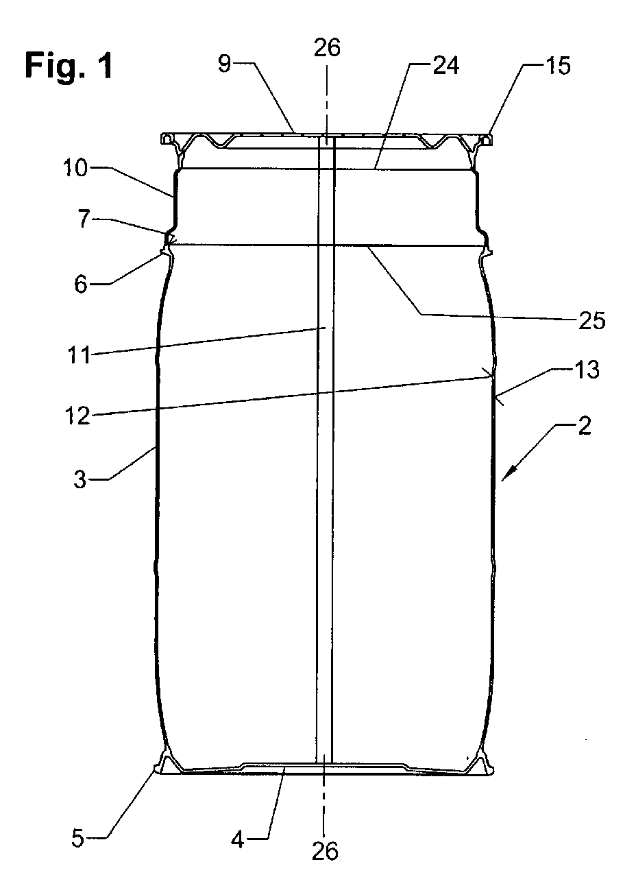
- Fig. 1
- eine Längsschnittdarstellung eines einer Blasformmaschine nach dem Blasformen und dem Abkühlen entnommenen Faßkörpers mit Fußring und geschlossenem Deckel,
- Fig. 2
- eine Längsschnittdarstellung von Faßrumpf und Faßdeckel nach dem Herausschneiden des für das Einführen eines Einschießblasdornes für den Blasvorgang erforderlichen Zwischenrings aus dem Faßkörper nach Fig. 1,
- Fig. 3
- eine Seitenansicht eines montierten Weithalsfasses mit Fußring und geschlossenem Deckel,
- Fig. 4
- eine ausschnittsweise vergrößerte Darstellung des Deckelbereichs des Weithalsfasses nach Fig. 3,
- Fig. 5
- einen vergrößerten Teilquerschnitt der Faßwand des Weithalsfasses nach Fig. 3, das einem Dreischichtenaufbau aufweist,
- Fig. 6
- einen der Fig. 5 entsprechenden Wandausschnitt eines Weithalsfasses mit einem Sechsschichtenaufbau, die
- Fign. 7a und 7b
- ausschnittsweise vergrößerte schematische Darstellungen einer geschlossenen und einer geöffneten Blasform mit einem blasgeformten Faßkörper,
- Fig. 8
- eine Längsschnittdarstellung eines entformten Faßkörpers mit Fußring und Spunddeckel sowie einem Zwischenring zum Einführen eines Einschießblasdornes,
- Fig. 9
- eine Längsschnittdarstellung eines entformten Faßkörpers mit Fußring und Spunddeckel sowie einem schmalen Zwischenring, wobei der Faßkörper mittels eines in das Spundloch des Be- und Entlüftungsspundes eingeführten Blasdornes blasgeformt wurde,
- Fig. 10
- eine perspektivische Darstellung eines montierten Weithalsfasses mit einer weiteren Ausführungsform eines geschlossenen Deckels und
- Fig. 11
- eine ausschnittsweise vergrößerte Darstellung des Deckelbereiches des Weithalsfasses nach Fig. 10.
- Fig. 1
- a longitudinal sectional view of a blow molding machine after blow molding and cooling removed barrel body with foot ring and lid closed,
- Fig. 2
- a longitudinal sectional view of Faßrumpf and Faßdeckel after cutting out the necessary for the insertion of Einschießblasdornes for the blowing intermediate ring from the barrel body of FIG. 1,
- Fig. 3
- a side view of a mounted wide-mouth barrel with foot ring and closed lid,
- Fig. 4
- a detail enlarged view of the lid portion of the wide-necked barrel of FIG. 3,
- Fig. 5
- 3 is an enlarged partial cross section of the barrel wall of the wide-necked barrel according to FIG. 3, which has a three-layer construction;
- Fig. 6
- one of Fig. 5 corresponding wall section of a wide-necked barrel with a six-layer structure, the
- FIGS. 7a and 7b
- partially enlarged schematic representations of a closed and an open blow mold with a blow-molded barrel body,
- Fig. 8
- a longitudinal sectional view of a demolded barrel body with foot ring and bung cover and an intermediate ring for inserting a Einschießblasdornes,
- Fig. 9
- a longitudinal sectional view of a demolded barrel body with foot ring and bung cover and a narrow intermediate ring, wherein the barrel body was blow-molded by means of a blow mandrel inserted into the bunghole of the ventilation and bung,
- Fig. 10
- a perspective view of a mounted wide-mouth barrel with a further embodiment of a closed lid and
- Fig. 11
- a detail enlarged view of the lid portion of the wide-necked barrel of FIG. 10th
Bei dem Extrusionsblasformen zur Herstellung von weithalsfässern aus einem thermoplastischem Kunststoff wird in der ersten Verfahrensstufe durch den Extrusionskopf einer Blasformmaschine ein mehrschichtiger, insbesondere ein dreischichtiger Kunststoffschlauch aus einem nichtleitenden Grundwerkstoff extrudiert, der aus einer Innenschicht, einer Mittelschicht, einer leitfähigen oder dauerantistischen Außenschicht sowie mindestens einem auf dem Umfang angeordneten Kontaktstreifen aus einem elektrisch leitenden Kunststoffmaterial besteht. Der extrudierte mehrschichtige Kunststoffschlauch wird nach Schließen des oberen Schlauchendes mit einem Schließwerkzeug mittels Blasluft, die durch einen in das untere Ende des Schlauches eingeführten Blasdorn eingeleitet wird, zu einem Vorformling vorgeblasen. In the extrusion blow molding for the production of wide-necked drums made of a thermoplastic material is in the first stage through the extrusion head of a Blow molding a multilayer, especially one three-layer plastic hose made of a non-conductive Base material extruded, consisting of an inner layer, a Middle class, a conductive or permanent Outer layer and at least one arranged on the circumference Contact strip made of an electrically conductive Plastic material exists. The extruded multilayered Plastic hose will close after closing the upper hose end with a closing tool by means of blown air, by a in introduced the lower end of the hose inserted mandrel is preformed to a preform.
Es besteht ferner die Möglichkeit, den extrudierten Schlauch nach Schließen des unteren Schlauchendes mittels über eine Düse im Extrusionskopf zugeführter Blasluft zu einem Vorformling vorzublasen.There is also the possibility of the extruded tube after closing the lower end of the hose via a nozzle In the extrusion head supplied blast air to a preform vorzublasen.
Anschließend wird nach dem Zusammenquetschen des unteren
Endes des Vorformlings mittels einer Schließeinheit und dem
Schließen der beiden Formhälften der geteilten Blasform 1, die
in den Fign. 7a und 7b dargestellt ist, in der zweiten
Verfahrensstufe der Vorformling zu einem in Fig. 1 dargestellten
Faßkörper 2 mit einem Faßrumpf 3, einem Boden 4 mit einem
Fußring 5, einer Bordur 6 am Faßrumpf 3 in Höhe des
Öffnungsrandes 7 des herzustellenden Weithalsfasses 8, einem
geschlossenen Deckel 9, einem Zwischenring 10 zwischen Bordur 6
und Deckel 9 sowie einem in den Deckel 9, den Zwischenring 10,
den Faßrumpf 3 und den Faßboden 4 integrierten elektrisch
leitenden Kontaktstreifen 11 vorgeblasen, der eine elektrische
Verbindung zwischen der Innenfläche 12 und der Oberfläche 13 des
Faßkörpers 2 bildet und dessen Stärke der Wandstärke des
Faßkörpers entspricht. Die Blasluft wird über einen oder mehrere
Blasdorne 14 zugeführt, der bzw. die in einen Abschnitt des
Vorformlings eingeschossen wird bzw. werden, der zu dem
Zwischenring 10 des Faßkörpers 2 blasgeformt wird.Subsequently, after squeezing the lower
End of the preform by means of a closing unit and the
Closing the two mold halves of the split blow mold 1, the
in the Fign. 7a and 7b is shown in the second
Process stage of the preform to one shown in Fig. 1
Beim Koextrudieren des mehrschichtigen Kunststoffschlauches in die Blasform wird der aus einem Extrusionskopf kontinuierlich oder diskontinuierlich austretende Materialschlauch an mindestens einer Stelle auf dem Umfang aufgespaltet und in den Spaltraum ein elektrisch leitfähiges Kunststoffmaterial zur Bildung eines Kontaktstreifens eingespritzt, der mit dem Vorformling homogen verschweißt. When coextruding the multilayer plastic tube in the blow mold, the from an extrusion head is continuous or discontinuously exiting material hose on split at least one point on the circumference and in the Gap space an electrically conductive plastic material for Forming a contact strip injected with the Preform homogeneously welded.
Bei der Faßausführung nach den Fign. 1 bis 4 wird der
Faßkörper 2 mit einem geschlossenen Deckel 9 blasgeformt, der
einen nach unten offenen U-förmigen Außenrand 15 mit einem
Dichtungsbett 16 zur Aufnahme einer Deckeldichtung 17 aufweist.
Beim Fertigblasen des Faßkörpers 2 in der Blasform 1 werden der
Deckelrand 15 und dessen Dichtungsbett 16 durch zwei sich
gegenläufig bewegende Formschieber 18, 19 verpreßt (Fig. 7a).
Durch das Verpressen des Deckelrandes wird ein formstabiler
Deckel mit einem einwandfreien, keine Nachbearbeitung
erfordernden Dichtungsbett ohne einen störenden Wulst im Bereich
der Formtrennebene blasgeformt.In the barrel execution according to Figs. 1 to 4 becomes the
Beim Fertigblasen eines Faßkörpers 2 in der Blasform 1 wird
ein umlaufender Versteifungswulst 20 an den Übergangsabschnitt
21 zwischen einer an den Außenrand 15 des Deckels 9
anschließenden Eingreifnut 22 für einen Faßgreifer und einem
unterhalb der Eingreifnut 22 angeformten Ringsteg 23 zur
Versteifung des Faßdeckels angeformt.When finished blowing a
Nach dem Abkühlen des Faßkörpers 2 mit dem geschlossenen
Deckel 9, dessen U-förmiger Außenrand 15 durch die Formschieber
18, 19 von innen und außen gekühlt wird, wird die Blasform 1
geöffnet und der Faßkörper 2 der Blasform entnommen (Fig. 7b).After cooling the
Anschließend wird entsprechend den Fign. 1, 2 und 7b der
Zwischenring 10 entlang den Solltrennlinien 24, 25 durch zwei
senkrecht zur Längsachse 26-26 des Faßkörpers 2 geführte
Schnitte aus diesem herausgeschnitten und die Schnittkanten 27,
28 des Faßrumpfes 3 und des Deckels 9 werden zum Entfernen des
Schnittgrates mit Heißluft beflammt.Subsequently, according to FIGS. 1, 2 and 7b of
Danach durchlaufen Faßrumpf 3 und Deckel 9 eine Kühlstrecke. Then
Nunmehr wird ein Dichtring 17 in das Dichtungsbett 16 des
Deckels 9 eingelegt und anschließend wird bei der Endmontage des
Weithalsfasses 8 der Deckel 9 mittels eines Spannringes 29 an
der Bordur 6 des Faßrumpfes 3 befestigt (Fign. 3 und 4).Now, a sealing
Fig. 5 zeigt einen Dreischichtenaufbau von Rumpf 3, Boden 4
und Deckel 9 des Weithalsfasses 8 mit einer Innenschicht 30,
einer Mittelschicht 31 und einer leitfähigen oder
dauerantistatischen Außenschicht 32, die beispielsweise einen
Leitrußanteil enthalten kann.FIG. 5 shows a three-layer structure of
Für die Herstellung der Mittelschicht 31 wird ein recyceltes
Granulat oder Mahlgut aus reinem Polyethylen und/oder
Polyethylen mit einem Leitrußanteil verwendet, und als
Ausgangsmaterial für die Innen- und die Außenschicht 30, 32
dient ein neuwertiges Polyethylen-Granulat.For the production of the
Fig. 6 zeigt einen Sechsschichtenaufbau eines Weithalsfasses
8 mit einer Innenschicht 30 aus reinem Polyethylen hoher Dichte
(HDPE), einer Sperrschicht 33 aus Polyamid (PA) oder einem
Ethylen-Vinylacetat-Copolimer (EVA) gegen die Permeation von
Sauerstoff und Kohlenwasserstoffen, die in zwei
Haftvermittlerschichten 34, 35 aus einem Polyethylen niedriger
Dichte (LLDPE) eingebettet ist, einer Mittelschicht 31 aus
recyceltem Granulat oder Mahlgut aus reinem Polyethylen hoher
Dichte und/oder Polyethylen hoher Dichte mit einem Leitrußanteil
sowie einer leitfähigen oder dauerantistatischen Außenschicht 32
aus Polyethylen hoher Dichte mit einem Leitrußanteil.Fig. 6 shows a six-layer structure of a
In den Faßrumpf 3, den Boden 4 und den Deckel 9 des
Weithalsfasses 8 ist mindestens ein elektrisch leitender
Kontaktstreifen 11 aus einem Polyethylen hoher Dichte mit einem
Leitrußanteil integriert, der eine elektrische Verbindung
zwischen der Innenfläche 12 und der Oberfläche 13 des
Weithalsfasses 8 bildet und dessen Stärke der Wandstärke 36 des
Fasses entspricht. Der elektrisch leitende Kontaktstreifen 11
verläuft parallel zur Faßlängsachse 26-26 über den zylindrischen
Faßrumpf 3 und radial über den Boden 4 und den geschlossenen
Deckel 9 des Weithalsfasses 8.In the
Das Weithalsfaß 8 ist über den elektrischen Kontaktstreifen
11 und die leitfähige oder dauerantistatische Außenschicht 32
elektrisch geerdet, so daß elektrische Ladungen, die an der
Innenfläche 12 des Fasses 8 und im flüssigen Füllgut oder im
Schüttgut sowie an der Faßoberfläche 13 auftreten, in den Boden
abgeleitet werden.The wide-
Nach dem vorbeschriebenen Verfahren können auch
Weithalsfässer 8 ohne Fußring mit einem gerundeten Übergang
zwischen Faßrumpf 3 und Faßboden 4 hergestellt werden (Fig. 10).After the procedure described above can also
Ferner besteht die Möglichkeit, nach dem vorbeschriebenen
Verfahren Weithalsfässer mit einem Spunddeckel 37 zu fertigen,
der einen Befüll- und Entnahmespund 38 und einen Be- und
Entlüftungsspund 39 aufweist (Fign. 8 und 9). Bei der
Herstellung von Weithalsfässern mit Spunddeckel 37 wird die
Blasluft zum Fertigblasen des geschlossenen Vorformlings über
das Spundloch 40 eines der beiden Spunde 38, 39 mittels eines
Blasdorns zugeführt. Über den bzw. die in den Zwischenring 10
des Faßkörpers eingeschossenen Blasdorn bzw. Blasdorne 14 kann
Spülluft in den fertiggeblasenen Faßkörper zum Abkühlen
desselben in der Blasform 1 eingeleitet werden. Bei der
Einleitung von Spülluft durch einen oder beide Spunde 39, 40 des
Spunddeckels 37 des fertiggeblasenen Faßkörpers 2 sind
Einschießblasdorne im Zwischenring 10 nicht mehr erforderlich,
so daß der Zwischenring schmaler gestaltet werden kann (Fig. 9). It is also possible, after the above
Method of making wide-mouth drums with a bung cap 37
the one filling and Entnahmespespund 38 and a loading and
Venting bung 39 has (Figures 8 and 9). In the
Production of wide-mouth barrels with spout lid 37 is the
Blown air to finish blowing the closed preform over
the
Die Fign. 10 und 11 zeigen ein nach dem vorbeschriebenen
Verfahren hergestelltes Weithalsfaß 8 mit einem geschlossenen
Deckel oder einem Spunddeckel 41, der einen Außenrand 42 und
einen Innenrand 43 mit einem nach unten offenen Ringraum 44 mit
einem Dichtungsbett 16 zur Aufnahme einer Deckeldichtung 17
aufweist, wobei der auf einem Faßrumpf 3 befestigte Deckel 41
mit seinem Außenrand 42 den Faßhals 45 umschließt und mit seinem
Innenrand 43, der über den unterhalb des Faßöffnungsrandes 7
gelegenen Deckelboden 46 vorsteht, in den Faßhals 45 eintaucht
und der Deckel 41 mit einem Spannring 29, der an einer mit
Abstand unterhalb des Öffnungsrandes 7 angeformten Bordur 47 des
Faßrumpfes 3 und an einem Ringflansch 48 des Deckelaußenrandes
42 angreift, auf dem Faßrumpf 3 befestigt wird.The Fign. 10 and 11 show one after the above
Method produced
In dem Eckbereich zwischen der Unterseite 49 des
Deckelbodens 46 und dem Innenrand 43 des Faßdeckels 41 ist ein
umlaufender Versteifungswulst 50 angeformt und an dem unteren
Ende des Innenrandes 43 des Faßdeckels 41 ist ein konischer
Versteifungsring 51 angeordnet.In the corner area between the bottom 49 of
Das vorbeschriebene Verfahren kann zur Herstellung von Weithalsfässern eingesetzt werde, die nicht elektrisch geerdet sind. In diesem Fall ist der in eine Blasform extrudierte ein- oder mehrschichtige Kunststoffschlauch nicht mit einem elektrisch leitfähigen Kunststoffmaterial ausgerüstet.The above-described method can be used for the production of Wide-necked barrels are used that are not electrically grounded are. In this case, the extruded into a blow mold is or multilayer plastic tubing not with one electrically conductive plastic material equipped.
Claims (13)
Priority Applications (1)
| Application Number | Priority Date | Filing Date | Title |
|---|---|---|---|
| PL05004633T PL1574442T3 (en) | 2004-03-11 | 2005-03-03 | A method of producing barrels with a wide neck from thermoplastic plastic |
Applications Claiming Priority (6)
| Application Number | Priority Date | Filing Date | Title |
|---|---|---|---|
| DE102004011915 | 2004-03-11 | ||
| DE102004011915 | 2004-03-11 | ||
| DE102005001649 | 2005-01-13 | ||
| DE102005001649A DE102005001649B4 (en) | 2004-03-11 | 2005-01-13 | Process for the production of wide-mouth drums of thermoplastic material |
| DE102005004548 | 2005-01-31 | ||
| DE102005004548A DE102005004548A1 (en) | 2004-03-11 | 2005-01-31 | Process for the production of wide-mouth drums of thermoplastic material |
Publications (3)
| Publication Number | Publication Date |
|---|---|
| EP1574442A2 true EP1574442A2 (en) | 2005-09-14 |
| EP1574442A3 EP1574442A3 (en) | 2006-09-13 |
| EP1574442B1 EP1574442B1 (en) | 2007-07-11 |
Family
ID=34830759
Family Applications (1)
| Application Number | Title | Priority Date | Filing Date |
|---|---|---|---|
| EP05004633A Expired - Lifetime EP1574442B1 (en) | 2004-03-11 | 2005-03-03 | Method for manufacturing a barrel made of thermoplastic material |
Country Status (14)
| Country | Link |
|---|---|
| US (1) | US7655177B2 (en) |
| EP (1) | EP1574442B1 (en) |
| JP (1) | JP3920291B2 (en) |
| CN (1) | CN100352737C (en) |
| AR (1) | AR053524A1 (en) |
| AT (1) | ATE366652T1 (en) |
| AU (1) | AU2005201077B2 (en) |
| BR (1) | BRPI0501680A (en) |
| DE (2) | DE102005004548A1 (en) |
| DK (1) | DK1574442T3 (en) |
| ES (1) | ES2287824T3 (en) |
| MX (1) | MXPA05002677A (en) |
| NO (1) | NO20051229L (en) |
| PL (1) | PL1574442T3 (en) |
Cited By (2)
| Publication number | Priority date | Publication date | Assignee | Title |
|---|---|---|---|---|
| EP1818162A3 (en) * | 2006-02-14 | 2008-01-16 | Gino Chiari | Process for producing open plastic containers by extrusion and blow moulding |
| WO2007038071A3 (en) * | 2005-09-23 | 2008-07-03 | Graham Packaging Co | Blow molded container, dispenser, and closure |
Families Citing this family (10)
| Publication number | Priority date | Publication date | Assignee | Title |
|---|---|---|---|---|
| BRPI0712033B1 (en) * | 2006-05-18 | 2018-01-23 | Mauser-Werke Gmbh | MULTI-LAYER PLASTIC CONTAINER AND METHOD FOR PRODUCING A MULTI-LAYER PLASTIC CONTAINER |
| DE202008002185U1 (en) | 2008-02-16 | 2008-04-17 | Schütz GmbH & Co. KGaA | Wide neck drum made of thermoplastic material |
| FI124163B (en) * | 2008-06-30 | 2014-04-15 | Uponor Infra Oy | Container |
| JP5321953B2 (en) * | 2008-07-28 | 2013-10-23 | 株式会社リコー | Optical scanning apparatus and image forming apparatus |
| BE1021612B1 (en) * | 2013-01-15 | 2015-12-18 | CARDIFF GROUP,naamloze vennootschap | HOLDER FOR A LIQUID PRODUCT AND A METHOD FOR MANUFACTURING SUCH A HOLDER. |
| CN106115101B (en) * | 2016-08-09 | 2018-05-29 | 江苏奇一科技有限公司 | A kind of barrel-shaped container of large scale heavy caliber using fabricated structure |
| CN110973028B (en) * | 2019-11-06 | 2024-08-30 | 青岛福润德机械有限公司 | PET combined floating ball and cladding floating ball |
| DE102022122136A1 (en) * | 2022-09-01 | 2024-03-07 | Greif International Holding B.V. | Process for producing a barrier layer laminate, barrier layer laminate and container made from the barrier layer laminate |
| CN115742257B (en) * | 2022-09-30 | 2026-04-03 | 苏州市繁盛塑料制品有限公司 | A plastic bucket processing production line and online control system |
| US12605880B2 (en) * | 2023-07-12 | 2026-04-21 | Ring Container Technologies, Llc | Packaging container manufacturing system and method |
Family Cites Families (19)
| Publication number | Priority date | Publication date | Assignee | Title |
|---|---|---|---|---|
| US2515093A (en) * | 1949-03-23 | 1950-07-11 | Elmer E Mills | Machine for making hollow articles |
| GB898377A (en) * | 1960-06-28 | 1962-06-06 | E R Holloway Ltd | Improvements relating to hollow plastic containers |
| US3198375A (en) * | 1962-05-01 | 1965-08-03 | Union Carbide Corp | Blow molded container |
| US3632717A (en) * | 1969-08-29 | 1972-01-04 | Harry C Schroeder | Method of making containers and lids therefor |
| US4091059A (en) * | 1976-09-23 | 1978-05-23 | Leonard Benoit Ryder | Method for blow molding and cooling plastic articles |
| BE898765A (en) * | 1983-02-17 | 1984-05-16 | Schuetz Udo | WIDE NECK CONTAINER, IN PLASTIC MATERIAL, WITH REMOVABLE LID |
| US4667384A (en) * | 1984-12-13 | 1987-05-26 | Continental Plastic Beverage Bottles, Inc. | Method of manufacturing a plastic container having an enlarged free end portion for receiving a metal end unit by double seaming |
| US4968242A (en) * | 1987-10-09 | 1990-11-06 | Ball Corporation | Apparatus for tandem molding of plastic containers |
| DE3913087A1 (en) * | 1989-04-21 | 1990-10-25 | Mauser Werke Gmbh | DEVICE FOR BLOW MOLDING A HOLLOW BODY |
| US5213753A (en) * | 1989-04-21 | 1993-05-25 | Mauser-Werke Gmbh | Method for compression molding flanges on a blow molded body to be severed into a vessel and lid |
| DE4130717A1 (en) * | 1991-09-14 | 1993-03-25 | Mauser Werke Gmbh | BLOW MOLDING MACHINE |
| DE9414955U1 (en) * | 1994-09-15 | 1994-12-15 | Mauser-Werke GmbH, 50321 Brühl | Lid barrel |
| US5964367A (en) * | 1992-10-28 | 1999-10-12 | Mauser-Werke Gmbh | Lidded barrel |
| DE4242370C1 (en) * | 1992-12-16 | 1994-05-11 | Schuetz Werke Gmbh Co Kg | Spigot plastics vessel - has cover held by welded ring strap which can be removed for vessel to used for another purpose or restored into new spigot vessel |
| KR100392531B1 (en) | 1994-09-15 | 2003-11-28 | 마우저-베르케 게엠베하 운트 코. 카게 | Barrel with lid |
| DE19811414C2 (en) * | 1998-03-17 | 2002-04-18 | Schuetz Werke Gmbh Co Kg | Process for the production of sheet piling and plastic lids and process for reconditioning of sheet piling |
| JP2003034346A (en) * | 2001-07-26 | 2003-02-04 | Sankei Sangyo Kk | Drum can cover, method of manufacturing the same, and cutting device used in the method |
| DE10242956B4 (en) * | 2002-09-17 | 2004-07-15 | Protechna S.A. | Transport and storage container for liquids and method for manufacturing the plastic inner container of the transport and storage container |
| DE10242955B4 (en) * | 2002-09-17 | 2005-03-10 | Schuetz Gmbh & Co Kgaa | Kunststoffaß and method for producing the barrel |
-
2005
- 2005-01-31 DE DE102005004548A patent/DE102005004548A1/en not_active Withdrawn
- 2005-03-03 DE DE502005000991T patent/DE502005000991D1/en not_active Expired - Fee Related
- 2005-03-03 DK DK05004633T patent/DK1574442T3/en active
- 2005-03-03 PL PL05004633T patent/PL1574442T3/en unknown
- 2005-03-03 EP EP05004633A patent/EP1574442B1/en not_active Expired - Lifetime
- 2005-03-03 AT AT05004633T patent/ATE366652T1/en not_active IP Right Cessation
- 2005-03-03 ES ES05004633T patent/ES2287824T3/en not_active Expired - Lifetime
- 2005-03-10 NO NO20051229A patent/NO20051229L/en not_active Application Discontinuation
- 2005-03-10 AU AU2005201077A patent/AU2005201077B2/en not_active Ceased
- 2005-03-10 JP JP2005066451A patent/JP3920291B2/en not_active Expired - Fee Related
- 2005-03-10 US US11/077,180 patent/US7655177B2/en not_active Expired - Fee Related
- 2005-03-10 CN CNB2005100550869A patent/CN100352737C/en not_active Expired - Fee Related
- 2005-03-10 MX MXPA05002677A patent/MXPA05002677A/en active IP Right Grant
- 2005-03-11 BR BR0501680-0A patent/BRPI0501680A/en not_active IP Right Cessation
- 2005-03-11 AR ARP050100965A patent/AR053524A1/en not_active Application Discontinuation
Cited By (2)
| Publication number | Priority date | Publication date | Assignee | Title |
|---|---|---|---|---|
| WO2007038071A3 (en) * | 2005-09-23 | 2008-07-03 | Graham Packaging Co | Blow molded container, dispenser, and closure |
| EP1818162A3 (en) * | 2006-02-14 | 2008-01-16 | Gino Chiari | Process for producing open plastic containers by extrusion and blow moulding |
Also Published As
| Publication number | Publication date |
|---|---|
| AU2005201077B2 (en) | 2007-03-22 |
| ES2287824T3 (en) | 2007-12-16 |
| MXPA05002677A (en) | 2005-10-06 |
| DK1574442T3 (en) | 2007-11-12 |
| NO20051229D0 (en) | 2005-03-10 |
| NO20051229L (en) | 2005-09-12 |
| DE102005004548A1 (en) | 2005-12-22 |
| EP1574442B1 (en) | 2007-07-11 |
| AU2005201077A1 (en) | 2005-09-29 |
| ATE366652T1 (en) | 2007-08-15 |
| BRPI0501680A (en) | 2005-11-08 |
| AR053524A1 (en) | 2007-05-09 |
| JP3920291B2 (en) | 2007-05-30 |
| EP1574442A3 (en) | 2006-09-13 |
| JP2005255254A (en) | 2005-09-22 |
| CN1666931A (en) | 2005-09-14 |
| PL1574442T3 (en) | 2007-12-31 |
| CN100352737C (en) | 2007-12-05 |
| US7655177B2 (en) | 2010-02-02 |
| DE502005000991D1 (en) | 2007-08-23 |
| US20050200053A1 (en) | 2005-09-15 |
Similar Documents
| Publication | Publication Date | Title |
|---|---|---|
| EP0182094B1 (en) | Method for making a container with a sealable opening, and container obtained thereby | |
| DE4242370C1 (en) | Spigot plastics vessel - has cover held by welded ring strap which can be removed for vessel to used for another purpose or restored into new spigot vessel | |
| DE69429096T2 (en) | MULTILAYERED PREFORMING FOR BLOW MOLDING AND METHOD FOR THE PRODUCTION THEREOF | |
| DE10054876C2 (en) | Double-walled fuel tank made of plastic | |
| DE69201437T2 (en) | MULTILAYER BOTTLE WITH A DETACHABLE INNER LAYER. | |
| EP1574442B1 (en) | Method for manufacturing a barrel made of thermoplastic material | |
| EP2069210B1 (en) | Packaging container and method of producing the same | |
| DE4034226C1 (en) | Wide necked plastics container - has border section below opening to accommodate tensioning ring for lid | |
| DE102008030318A1 (en) | Process for producing a plastic container | |
| DE60112408T2 (en) | METHOD FOR PRODUCING A PLASTIC FUEL TANK | |
| WO2013104385A1 (en) | Plastic container for a deodorant roller | |
| EP3487790B1 (en) | Waste water container, method for the production thereof | |
| DE60107514T2 (en) | Process for producing a multilayer hollow body and blow molding tool with pinch edges | |
| EP0189750A2 (en) | Method of making hollow bodies with multi-layered walls | |
| DE102019135439A1 (en) | Containers with in-mold labels and / or with labels, processes and devices for the production thereof, as well as containers | |
| DE9007482U1 (en) | Plastic hollow body with plastic lid | |
| EP1401071A2 (en) | Thermoplastic drum and its method of manufacturing | |
| WO2008071299A1 (en) | Fuel tank made of thermoplastic synthetic material with functional built-in structures for ventilation and deaeration, for the withdrawing of fuel or the like | |
| DE69415243T2 (en) | RESIN BOTTLE | |
| DE10018310A1 (en) | Plastic fuel tank with built-in components is made by blow molding, separated into halves and re-joined to form one-piece tank | |
| DE4322514C2 (en) | Process for producing a container with a flexible inner bag | |
| DE4205332A1 (en) | CONNECTING A METAL CONNECTING ELEMENT WITH A BLOW-MOLDED PLASTIC CONTAINER | |
| EP4411198A2 (en) | High pressure vessel | |
| DE102005001649A1 (en) | Blow-molding multilayer, thermoplastic, wide-necked tub container with removable cover and ring clamp closure, includes earthing conductive strip between inner and outer surfaces | |
| EP0943420B1 (en) | Method for manufacturing plastic bunghole barrels and lid covered barrels and method for reconditioning of bunghole barrels |
Legal Events
| Date | Code | Title | Description |
|---|---|---|---|
| PUAI | Public reference made under article 153(3) epc to a published international application that has entered the european phase |
Free format text: ORIGINAL CODE: 0009012 |
|
| AK | Designated contracting states |
Kind code of ref document: A2 Designated state(s): AT BE BG CH CY CZ DE DK EE ES FI FR GB GR HU IE IS IT LI LT LU MC NL PL PT RO SE SI SK TR |
|
| AX | Request for extension of the european patent |
Extension state: AL BA HR LV MK YU |
|
| PUAL | Search report despatched |
Free format text: ORIGINAL CODE: 0009013 |
|
| AK | Designated contracting states |
Kind code of ref document: A3 Designated state(s): AT BE BG CH CY CZ DE DK EE ES FI FR GB GR HU IE IS IT LI LT LU MC NL PL PT RO SE SI SK TR |
|
| AX | Request for extension of the european patent |
Extension state: AL BA HR LV MK YU |
|
| RIC1 | Information provided on ipc code assigned before grant |
Ipc: B29C 69/00 20060101AFI20060810BHEP Ipc: B65D 8/04 20060101ALI20060810BHEP Ipc: B65D 45/32 20060101ALI20060810BHEP |
|
| 17P | Request for examination filed |
Effective date: 20061127 |
|
| GRAP | Despatch of communication of intention to grant a patent |
Free format text: ORIGINAL CODE: EPIDOSNIGR1 |
|
| AKX | Designation fees paid |
Designated state(s): AT BE BG CH CY CZ DE DK EE ES FI FR GB GR HU IE IS IT LI LT LU MC NL PL PT RO SE SI SK TR |
|
| GRAS | Grant fee paid |
Free format text: ORIGINAL CODE: EPIDOSNIGR3 |
|
| GRAA | (expected) grant |
Free format text: ORIGINAL CODE: 0009210 |
|
| AK | Designated contracting states |
Kind code of ref document: B1 Designated state(s): AT BE BG CH CY CZ DE DK EE ES FI FR GB GR HU IE IS IT LI LT LU MC NL PL PT RO SE SI SK TR |
|
| REG | Reference to a national code |
Ref country code: GB Ref legal event code: FG4D Free format text: NOT ENGLISH |
|
| REG | Reference to a national code |
Ref country code: CH Ref legal event code: EP |
|
| GBT | Gb: translation of ep patent filed (gb section 77(6)(a)/1977) |
Effective date: 20070711 |
|
| REF | Corresponds to: |
Ref document number: 502005000991 Country of ref document: DE Date of ref document: 20070823 Kind code of ref document: P |
|
| REG | Reference to a national code |
Ref country code: IE Ref legal event code: FG4D Free format text: LANGUAGE OF EP DOCUMENT: GERMAN |
|
| REG | Reference to a national code |
Ref country code: SE Ref legal event code: TRGR |
|
| ET | Fr: translation filed | ||
| REG | Reference to a national code |
Ref country code: DK Ref legal event code: T3 |
|
| REG | Reference to a national code |
Ref country code: ES Ref legal event code: FG2A Ref document number: 2287824 Country of ref document: ES Kind code of ref document: T3 |
|
| REG | Reference to a national code |
Ref country code: PL Ref legal event code: T3 |
|
| PG25 | Lapsed in a contracting state [announced via postgrant information from national office to epo] |
Ref country code: LT Free format text: LAPSE BECAUSE OF FAILURE TO SUBMIT A TRANSLATION OF THE DESCRIPTION OR TO PAY THE FEE WITHIN THE PRESCRIBED TIME-LIMIT Effective date: 20070711 Ref country code: NL Free format text: LAPSE BECAUSE OF FAILURE TO SUBMIT A TRANSLATION OF THE DESCRIPTION OR TO PAY THE FEE WITHIN THE PRESCRIBED TIME-LIMIT Effective date: 20070711 Ref country code: PT Free format text: LAPSE BECAUSE OF FAILURE TO SUBMIT A TRANSLATION OF THE DESCRIPTION OR TO PAY THE FEE WITHIN THE PRESCRIBED TIME-LIMIT Effective date: 20071211 Ref country code: IS Free format text: LAPSE BECAUSE OF FAILURE TO SUBMIT A TRANSLATION OF THE DESCRIPTION OR TO PAY THE FEE WITHIN THE PRESCRIBED TIME-LIMIT Effective date: 20071111 Ref country code: BG Free format text: LAPSE BECAUSE OF FAILURE TO SUBMIT A TRANSLATION OF THE DESCRIPTION OR TO PAY THE FEE WITHIN THE PRESCRIBED TIME-LIMIT Effective date: 20071011 |
|
| NLV1 | Nl: lapsed or annulled due to failure to fulfill the requirements of art. 29p and 29m of the patents act | ||
| REG | Reference to a national code |
Ref country code: IE Ref legal event code: FD4D |
|
| PG25 | Lapsed in a contracting state [announced via postgrant information from national office to epo] |
Ref country code: GR Free format text: LAPSE BECAUSE OF FAILURE TO SUBMIT A TRANSLATION OF THE DESCRIPTION OR TO PAY THE FEE WITHIN THE PRESCRIBED TIME-LIMIT Effective date: 20071012 |
|
| PLBE | No opposition filed within time limit |
Free format text: ORIGINAL CODE: 0009261 |
|
| STAA | Information on the status of an ep patent application or granted ep patent |
Free format text: STATUS: NO OPPOSITION FILED WITHIN TIME LIMIT |
|
| PG25 | Lapsed in a contracting state [announced via postgrant information from national office to epo] |
Ref country code: SK Free format text: LAPSE BECAUSE OF FAILURE TO SUBMIT A TRANSLATION OF THE DESCRIPTION OR TO PAY THE FEE WITHIN THE PRESCRIBED TIME-LIMIT Effective date: 20070711 Ref country code: CZ Free format text: LAPSE BECAUSE OF FAILURE TO SUBMIT A TRANSLATION OF THE DESCRIPTION OR TO PAY THE FEE WITHIN THE PRESCRIBED TIME-LIMIT Effective date: 20070711 Ref country code: IE Free format text: LAPSE BECAUSE OF FAILURE TO SUBMIT A TRANSLATION OF THE DESCRIPTION OR TO PAY THE FEE WITHIN THE PRESCRIBED TIME-LIMIT Effective date: 20070711 |
|
| 26N | No opposition filed |
Effective date: 20080414 |
|
| PG25 | Lapsed in a contracting state [announced via postgrant information from national office to epo] |
Ref country code: RO Free format text: LAPSE BECAUSE OF FAILURE TO SUBMIT A TRANSLATION OF THE DESCRIPTION OR TO PAY THE FEE WITHIN THE PRESCRIBED TIME-LIMIT Effective date: 20070711 |
|
| BERE | Be: lapsed |
Owner name: SCHUTZ G.M.B.H. & CO. KGAA Effective date: 20080331 |
|
| PG25 | Lapsed in a contracting state [announced via postgrant information from national office to epo] |
Ref country code: MC Free format text: LAPSE BECAUSE OF NON-PAYMENT OF DUE FEES Effective date: 20080331 |
|
| PG25 | Lapsed in a contracting state [announced via postgrant information from national office to epo] |
Ref country code: EE Free format text: LAPSE BECAUSE OF FAILURE TO SUBMIT A TRANSLATION OF THE DESCRIPTION OR TO PAY THE FEE WITHIN THE PRESCRIBED TIME-LIMIT Effective date: 20070711 |
|
| PG25 | Lapsed in a contracting state [announced via postgrant information from national office to epo] |
Ref country code: BE Free format text: LAPSE BECAUSE OF NON-PAYMENT OF DUE FEES Effective date: 20080331 |
|
| PGFP | Annual fee paid to national office [announced via postgrant information from national office to epo] |
Ref country code: DK Payment date: 20090324 Year of fee payment: 5 Ref country code: ES Payment date: 20090211 Year of fee payment: 5 |
|
| PGFP | Annual fee paid to national office [announced via postgrant information from national office to epo] |
Ref country code: FI Payment date: 20090211 Year of fee payment: 5 Ref country code: PL Payment date: 20090116 Year of fee payment: 5 |
|
| PG25 | Lapsed in a contracting state [announced via postgrant information from national office to epo] |
Ref country code: SI Free format text: LAPSE BECAUSE OF FAILURE TO SUBMIT A TRANSLATION OF THE DESCRIPTION OR TO PAY THE FEE WITHIN THE PRESCRIBED TIME-LIMIT Effective date: 20070711 |
|
| PGFP | Annual fee paid to national office [announced via postgrant information from national office to epo] |
Ref country code: GB Payment date: 20090225 Year of fee payment: 5 |
|
| PG25 | Lapsed in a contracting state [announced via postgrant information from national office to epo] |
Ref country code: CY Free format text: LAPSE BECAUSE OF FAILURE TO SUBMIT A TRANSLATION OF THE DESCRIPTION OR TO PAY THE FEE WITHIN THE PRESCRIBED TIME-LIMIT Effective date: 20070711 |
|
| PG25 | Lapsed in a contracting state [announced via postgrant information from national office to epo] |
Ref country code: AT Free format text: LAPSE BECAUSE OF NON-PAYMENT OF DUE FEES Effective date: 20080303 |
|
| PGFP | Annual fee paid to national office [announced via postgrant information from national office to epo] |
Ref country code: DE Payment date: 20090525 Year of fee payment: 5 Ref country code: IT Payment date: 20090326 Year of fee payment: 5 Ref country code: SE Payment date: 20090325 Year of fee payment: 5 |
|
| PGFP | Annual fee paid to national office [announced via postgrant information from national office to epo] |
Ref country code: FR Payment date: 20090116 Year of fee payment: 5 |
|
| REG | Reference to a national code |
Ref country code: CH Ref legal event code: PL |
|
| PG25 | Lapsed in a contracting state [announced via postgrant information from national office to epo] |
Ref country code: LI Free format text: LAPSE BECAUSE OF NON-PAYMENT OF DUE FEES Effective date: 20090331 Ref country code: CH Free format text: LAPSE BECAUSE OF NON-PAYMENT OF DUE FEES Effective date: 20090331 |
|
| PG25 | Lapsed in a contracting state [announced via postgrant information from national office to epo] |
Ref country code: HU Free format text: LAPSE BECAUSE OF FAILURE TO SUBMIT A TRANSLATION OF THE DESCRIPTION OR TO PAY THE FEE WITHIN THE PRESCRIBED TIME-LIMIT Effective date: 20080112 Ref country code: LU Free format text: LAPSE BECAUSE OF NON-PAYMENT OF DUE FEES Effective date: 20080303 |
|
| PG25 | Lapsed in a contracting state [announced via postgrant information from national office to epo] |
Ref country code: TR Free format text: LAPSE BECAUSE OF FAILURE TO SUBMIT A TRANSLATION OF THE DESCRIPTION OR TO PAY THE FEE WITHIN THE PRESCRIBED TIME-LIMIT Effective date: 20070711 |
|
| EUG | Se: european patent has lapsed | ||
| REG | Reference to a national code |
Ref country code: DK Ref legal event code: EBP |
|
| GBPC | Gb: european patent ceased through non-payment of renewal fee |
Effective date: 20100303 |
|
| PG25 | Lapsed in a contracting state [announced via postgrant information from national office to epo] |
Ref country code: FI Free format text: LAPSE BECAUSE OF NON-PAYMENT OF DUE FEES Effective date: 20100303 |
|
| REG | Reference to a national code |
Ref country code: FR Ref legal event code: ST Effective date: 20101130 |
|
| PG25 | Lapsed in a contracting state [announced via postgrant information from national office to epo] |
Ref country code: FR Free format text: LAPSE BECAUSE OF NON-PAYMENT OF DUE FEES Effective date: 20100331 |
|
| PG25 | Lapsed in a contracting state [announced via postgrant information from national office to epo] |
Ref country code: DE Free format text: LAPSE BECAUSE OF NON-PAYMENT OF DUE FEES Effective date: 20101001 |
|
| PG25 | Lapsed in a contracting state [announced via postgrant information from national office to epo] |
Ref country code: GB Free format text: LAPSE BECAUSE OF NON-PAYMENT OF DUE FEES Effective date: 20100303 Ref country code: IT Free format text: LAPSE BECAUSE OF NON-PAYMENT OF DUE FEES Effective date: 20100303 |
|
| REG | Reference to a national code |
Ref country code: ES Ref legal event code: FD2A Effective date: 20110415 |
|
| PG25 | Lapsed in a contracting state [announced via postgrant information from national office to epo] |
Ref country code: DK Free format text: LAPSE BECAUSE OF NON-PAYMENT OF DUE FEES Effective date: 20100331 |
|
| PG25 | Lapsed in a contracting state [announced via postgrant information from national office to epo] |
Ref country code: ES Free format text: LAPSE BECAUSE OF NON-PAYMENT OF DUE FEES Effective date: 20110404 |
|
| PG25 | Lapsed in a contracting state [announced via postgrant information from national office to epo] |
Ref country code: ES Free format text: LAPSE BECAUSE OF NON-PAYMENT OF DUE FEES Effective date: 20100304 |
|
| REG | Reference to a national code |
Ref country code: PL Ref legal event code: LAPE |
|
| PG25 | Lapsed in a contracting state [announced via postgrant information from national office to epo] |
Ref country code: PL Free format text: LAPSE BECAUSE OF NON-PAYMENT OF DUE FEES Effective date: 20100303 |
|
| PG25 | Lapsed in a contracting state [announced via postgrant information from national office to epo] |
Ref country code: SE Free format text: LAPSE BECAUSE OF NON-PAYMENT OF DUE FEES Effective date: 20100304 |