EP1574423B1 - Structure avant pour un véhicule automobile - Google Patents
Structure avant pour un véhicule automobile Download PDFInfo
- Publication number
- EP1574423B1 EP1574423B1 EP05004096A EP05004096A EP1574423B1 EP 1574423 B1 EP1574423 B1 EP 1574423B1 EP 05004096 A EP05004096 A EP 05004096A EP 05004096 A EP05004096 A EP 05004096A EP 1574423 B1 EP1574423 B1 EP 1574423B1
- Authority
- EP
- European Patent Office
- Prior art keywords
- front structure
- body part
- deformation
- filling piece
- wing element
- Prior art date
- Legal status (The legal status is an assumption and is not a legal conclusion. Google has not performed a legal analysis and makes no representation as to the accuracy of the status listed.)
- Expired - Lifetime
Links
- 239000002184 metal Substances 0.000 claims abstract description 6
- 239000004033 plastic Substances 0.000 claims abstract description 6
- 229920003023 plastic Polymers 0.000 claims abstract description 6
- 229920001971 elastomer Polymers 0.000 claims description 3
- 239000000463 material Substances 0.000 claims description 2
- 230000001413 cellular effect Effects 0.000 claims 1
- 239000000945 filler Substances 0.000 abstract description 55
- 238000002485 combustion reaction Methods 0.000 description 3
- 238000010276 construction Methods 0.000 description 3
- 239000000853 adhesive Substances 0.000 description 2
- 230000001070 adhesive effect Effects 0.000 description 2
- 239000007789 gas Substances 0.000 description 2
- 238000003466 welding Methods 0.000 description 2
- 239000011324 bead Substances 0.000 description 1
- 230000005540 biological transmission Effects 0.000 description 1
- 230000001747 exhibiting effect Effects 0.000 description 1
- 229920001821 foam rubber Polymers 0.000 description 1
- 238000009413 insulation Methods 0.000 description 1
- 238000004519 manufacturing process Methods 0.000 description 1
- 238000005406 washing Methods 0.000 description 1
Images


Classifications
-
- B—PERFORMING OPERATIONS; TRANSPORTING
- B60—VEHICLES IN GENERAL
- B60R—VEHICLES, VEHICLE FITTINGS, OR VEHICLE PARTS, NOT OTHERWISE PROVIDED FOR
- B60R21/00—Arrangements or fittings on vehicles for protecting or preventing injuries to occupants or pedestrians in case of accidents or other traffic risks
- B60R21/34—Protecting non-occupants of a vehicle, e.g. pedestrians
-
- B—PERFORMING OPERATIONS; TRANSPORTING
- B62—LAND VEHICLES FOR TRAVELLING OTHERWISE THAN ON RAILS
- B62D—MOTOR VEHICLES; TRAILERS
- B62D25/00—Superstructure or monocoque structure sub-units; Parts or details thereof not otherwise provided for
- B62D25/08—Front or rear portions
- B62D25/16—Mud-guards or wings; Wheel cover panels
- B62D25/163—Mounting devices
-
- B—PERFORMING OPERATIONS; TRANSPORTING
- B60—VEHICLES IN GENERAL
- B60R—VEHICLES, VEHICLE FITTINGS, OR VEHICLE PARTS, NOT OTHERWISE PROVIDED FOR
- B60R21/00—Arrangements or fittings on vehicles for protecting or preventing injuries to occupants or pedestrians in case of accidents or other traffic risks
- B60R21/34—Protecting non-occupants of a vehicle, e.g. pedestrians
- B60R2021/343—Protecting non-occupants of a vehicle, e.g. pedestrians using deformable body panel, bodywork or components
Definitions
- the invention relates to a front construction for a motor vehicle with front fenders seen in the intended direction of travel, with a body part arranged at a distance below the fender and with a deformation device arranged between the body part and the fenders, wherein the deformation device has a flexible filler piece made of plastic and wherein the filler closes a gap between the body part and the fender.
- Such a front is in the DE 102 33 474 A1 described.
- the filler thus extends between the body part and the overlying, the hood and already almost horizontally extending end portion of the fender.
- the area between the side part of the fender and the filler is free.
- the state of the art is also the DE 29 34 060 A1 to call.
- the deformation device of this front construction has a semicircularly curved in cross-section sheet metal between the inner edge of the fender and the underlying body part. If the head of a pedestrian strikes the fender vertically in the event of an accident, the deformation device absorbs the impact energy, so that the head impact should be smooth.
- the deformation device also has a semicircular, the fender vertically supporting plate and a arranged between the body part and a side portion of the fender support part.
- a disadvantage of the known front end is their low rigidity in the operation of the motor vehicle, which results from the requirement for the vertical compliance of the fender. By leaning against the fender can in the worst case, the fender abut a arranged between the fenders hood. Furthermore, it is disadvantageous in the known front structures that engine noise between the fender and the body part can penetrate to the outside.
- a fender arrangement for a motor vehicle has become known in which a sheet connected to the fender has a plurality of individual tabs as deformation members.
- the plate having the deformation members is connected via an adhesive bead with the fender and supports it from the side.
- a disadvantage of the fender arrangement is that an inaccurate adhesive application can lead to a deformation of the fender. Continue to penetrate in this fender arrangement between the flaps engine noise to the outside.
- the invention is based on the problem of designing a front structure of the type mentioned above so that it is designed sufficiently yielding in a pedestrian impact, but has sufficient stability during operation. For example, an abutment of the fender on a hood arranged between the fenders should be avoided by leaning on or washing the motor vehicle.
- the filler supports the side portion of the fender laterally.
- the filler takes on laterally introduced into the fender forces.
- the filler is at least partially to be arranged between the side region of the fender and the body part.
- the rigidity of the deformation device at the individual points of the fender can be adjusted by a corresponding configuration of the filler.
- the filler can support the fender surface and thus absorb forces occurring during operation of the motor vehicle.
- An additional panel to prevent the escape of engine noise between the fender and the body part is not required thanks to the invention, since the filler can be designed soundproof with appropriate choice of material and the deformation of the members Covered gap between the body part and fender covered.
- the deformation device exclusively on the filler.
- the deformation device comprises deformation members made of sheet metal and when the filler piece is arranged between the deformation members.
- the deformation members made of sheet metal can be arranged at intended locations in addition to the filler piece, to which only an exclusive support by the filler piece is insufficient.
- the filler extends over the entire length of the fender.
- the assembly of the front of the invention requires a particularly low cost when the filler is made in one piece.
- the filler can according to an advantageous embodiment of the invention very strongly dampens transmission of sound when the filler piece has a layer of sponge rubber on its side adjacent to the fender side.
- the filler is glued to the body part and / or the fender.
- An escape of engine compartment gases between the fender and the body part can be easily avoided according to another advantageous embodiment of the invention, when the filler closes the space between the fender and the body part gas-tight.
- the determination of the stability of the filler in a head impact on the fender designed according to another advantageous embodiment of the invention is particularly simple if the filler has deformation bars.
- the deformation webs may be formed, for example honeycomb or circular segment or as vertical buckling rods.
- the deformation bars can be provided according to another advantageous embodiment of the invention with very large dimensions and lead into the side area of the fender, when a deformation webs exhibiting portion of the filler between Verschraubungsstellen with the fender and / or the body part is arranged.
- the filler has according to another advantageous embodiment of the invention in the horizontal direction, a high stability and in the vertical direction to an almost arbitrarily adjustable stability, when the deformation bars vertically inclined from the fender to the body part and are guided horizontally up to the side area of the fender.
- the filler can be provided according to another advantageous embodiment of the invention, at least in some areas with a high elasticity when the filler has a wavy structure, with corrugations of the filler are arranged parallel to the edge adjacent to the fender edge.
- the assembly and disassembly of the fender make constructive particularly simple when the filler is bolted to the body part and / or the fender.
- the filler has holding means provided for holding components to be laid in an engine compartment.
- the holding means are formed as brackets. In these brackets, for example, harnesses and Bowden cables can be locked.
- the filler has a concealed by a panel chamber.
- the Bowden cables or wiring harnesses can be placed in the filler.
- the mounting of the filler requires according to another advantageous embodiment of the invention, a particularly low cost when the diaphragm is connected via a film hinge with a lateral boundary of the chamber.
- the stiffness of the deformation device can be adjusted easily according to another advantageous embodiment of the invention, when the deformation members have a U-shaped bent portion with its base attached to the fender and assign with legs on the body part.
- a plastic deformation of the deformation device can be according to another advantageous embodiment of the invention easily avoided if connected to the base of the opposite ends of the legs of the U-shaped portion of the deformation members parallel to the body part guided sections and if at the parallel guided sections connect the body part assigning legs.
- the guided parallel to the fender sections allow a slight elastic compliance of the deformation members.
- forces occurring in a head impact can be dampened, uninfluenced by the lateral support of the fender, if the deformation members support the fender exclusively vertically.
- the fender laterally supporting filler does not affect the vertical compliance of the fender.
- the deformation members can be mounted on the fender in a particularly cost-effective manner, for example by spot welding, when the deformation members are fastened to a water channel arranged at the hood-facing boundary of the fenders.
- a water channel is covered by the hood and is therefore not visible in the mounted state of the motor vehicle.
- the front construction according to the invention is structurally particularly simple if the deformation members are designed as individual components fastened to the mudguard and the body part. Furthermore, the production of the deformation members as individual components allows a particularly easy determination of the stability of the deformation device.
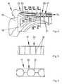
- FIG. 1 shows a right portion of a front structure 1 of a motor vehicle in cross-section and a subsequent to the front building 1 windscreen 2.
- the front building 1 has a pivotally mounted on a hinge 3 hood 4, which covers in its drawn position a schematically illustrated internal combustion engine 5 of the motor vehicle.
- the front part 1 is bounded by a fender 6.
- the fender 6 is attached to a likewise schematically illustrated body part 7 via a deformation device 8.
- the fender 6 At its edge adjacent to the hood 4, the fender 6 has a water channel 9. A lateral boundary of the hood 4 protrudes into the water channel 9.
- the deformation device 8 has a deformation member 10 made of sheet metal and a filler piece 11 made of plastic.
- the filler piece 11 supports the side region of the fender 6 on the body part 7.
- the deformation member 10 is attached to the underside of the water channel 9 and supports vertically acting on the fender 6 forces on the body part 7 from.
- the filler 11 is glued in a space between the mudguard 6 and the body part 7 and gives the mudguard 6 the necessary lateral rigidity. At the same time it seals the space of the internal combustion engine 5 against escaping gases and sound.
- FIG. 2 shows the front building FIG. 1 In a sectional view along the line II - II. It can be seen that a plurality of individual deformation members 10 are secured between the fender 6 and the hood 4. The deformation members 10 are spaced from each other. To simplify the drawing, the filler 11 is made FIG. 1 not shown.
- the deformation members 10 each have a U-shaped section 12. The base of the U-shaped portion 12 is fixed to the underside of the water channel 9 of the fender 6, for example by spot welding. At the fender 6 remote from the ends of the legs 13 of the U-shaped portion 12 are guided parallel to the body part 7 guided sections 14. At the guided parallel to the body part sections 14 close to the body part 7 tapered leg 15 whose free ends are connected to the body part 7.
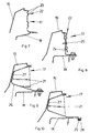
- FIG. 3 shows in a perspective sectional view of a portion of the fender 6 from the FIGS. 1 and 2 with the deformation members attached thereto 10.
- the filler 11 is made FIG. 1 not shown. It can be seen that the deformation members 10 are arranged exclusively in the region of the water channel 9 of the fender 6 and thus attenuate forces introduced vertically into the fender 6. Such forces can occur in a head impact of a pedestrian.
- FIG. 4 shows in perspective another embodiment of the front 16, in which a deformation device 34 has a filler 17 made of plastic and closes a gap between a body part 18 and a fender 19 seen from the engine compartment side.
- the filling piece 17 has a section 20 with deformation webs 21 and a section 22 with corrugations 23.
- the deformation webs 21 are arranged diamond-shaped to each other and vertically inclined and extend horizontally to near the inside of the fender 19th
- FIG. 5 shows an alternative embodiment of the filler 17 from FIG. 4 with the deformation webs 21 having portion 20.
- the deformation webs 21 are arranged vertically here and thus formed as buckling bars. In the case of vertical loading, the deformation webs 21 buckle and therefore allow yielding of the in FIG. 4 shown fender 19 in a head impact of a pedestrian.
- FIG. 6 shows a further embodiment of the deformation webs 21 having portion 20 of the filler 17 from FIG. 4 , The deformation webs 21 are arranged here in a circle segment.
- the deformation webs 21 designed as buckling rods or arranged in the shape of a circle segment can, as an alternative or in addition to those in FIGS FIG. 4 be shown, diamond-shaped deformation webs 21 may be provided.
- FIG. 7 shows enlarged a sectional view through the filler 17 FIG. 4 with adjacent areas of the fender 19 and the body part 18 along the line VII - VII. It can be seen here that the corrugations 23 of the wave-shaped portion 22 of the filler 17 are arranged parallel to the fender 19 facing the boundary. These corrugations 23 allow folding of the filler 17 in a head impact of a pedestrian on the fender 19th
- FIG. 8 shows enlarged a sectional view through the front 16 of FIG. 4 along the line VIII - VIII in the region of attachment of the fender 19 on the body part 18.
- the fender 19 is made in one piece with a guided to the body part 18 deformation member 24.
- the deformation member 24 is screwed to the body part 18.
- the filler 17 is attached via a clip 25 to the deformation member 24.
- FIG. 9 shows enlarged a sectional view through the filler 17 FIG. 4 along the line IX - IX In the region of its attachment to the body part 18. It can be seen that the filler 17 has an arcuate wall 26 and the deformation webs 21 are disposed within the arcuate wall 26. The arcuate wall 26 is screwed to the body part 18 and is glued to its the fender 19 laterally supporting area with a layer of sponge rubber 27.
- FIG. 10 shows enlarged in a sectional view through the front 16 FIG. 4 along the line X - X, that a clamp-shaped holding means 28 is made in one piece with the filler 17.
- the holding means 28 holds a laid in the front 16 harness 29 or Bowden cable.
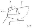
- FIG. 11 shows a cross section through a filler 30, which extends from the FIG. 4 only differs in that a chamber 31 for receiving any, not shown components of a panel 32 is closed.
- the diaphragm 32 is hinged via a film hinge 33 to the filler 30 and can be locked on this.
Landscapes
- Engineering & Computer Science (AREA)
- Mechanical Engineering (AREA)
- Chemical & Material Sciences (AREA)
- Combustion & Propulsion (AREA)
- Transportation (AREA)
- Body Structure For Vehicles (AREA)
- Vehicle Body Suspensions (AREA)
- Fluid-Damping Devices (AREA)
- Glass Compositions (AREA)
Claims (20)
- Structure avant (1, 16) pour un véhicule automobile comprenant des ailes (6, 19) avant vues dans le sens de marche prévu, avec une partie de carrosserie (7, 18) disposée à distance au-dessous des ailes (6, 19) et un dispositif de déformation (8, 34) disposé entre la partie de carrosserie (7, 18) et les ailes (6, 19), le dispositif de déformation (8, 34) présentant une pièce de remplissage (11, 17, 30) souple et fabriquée en matière plastique et la pièce de remplissage (11, 17, 30) fermant un intervalle entre la partie de carrosserie (7, 18) et l'aile (6, 19), caractérisée en ce que la pièce de remplissage (11, 17, 30) soutient latéralement la zone latérale de l'aile (7, 19).
- Structure avant (1, 16) selon la revendication 1, caractérisée en ce que le dispositif de déformation (8, 34) présente des organes de déformation (10, 24) fabriqués en tôle et en ce que la pièce de remplissage (11, 17, 30) est disposée entre les organes de déformation (10, 24).
- Structure avant (1, 16) selon la revendication 1 ou 2, caractérisée en ce que la pièce de remplissage (11, 17, 30) s'étend, vue dans le sens de marche, sur toute la longueur de l'aile (6,19).
- Structure avant (1, 16) selon au moins l'une des revendications précédentes, caractérisée en ce que la pièce de remplissage (11, 17, 30) est fabriquée d'une seule pièce.
- Structure avant (16) selon au moins l'une des revendications précédentes, caractérisée en ce que la pièce de remplissage (17) présente une couche (27) de caoutchouc cellulaire sur sa face adjacente à l'aile (19).
- Structure avant (1, 16) selon au moins l'une des revendications précédentes, caractérisée en ce que la pièce de remplissage (11, 17, 30) est collée sur la partie de carrosserie (7, 18) et/ou l'aile (6, 19).
- Structure avant (1, 16) selon au moins l'une des revendications précédentes, caractérisée en ce que la pièce de remplissage (11, 17, 30) ferme de façon étanche au gaz l'espace entre l'aile (6, 19) et la partie de carrosserie (7, 18).
- Structure avant (16) selon au moins l'une des revendications précédentes, caractérisée en ce que la pièce de remplissage (17, 30) présente des nervures de déformation (21).
- Structure avant (16) selon la revendication 8, caractérisée en ce qu'un tronçon (20) présentant les nervures de déformation (21), de la pièce de remplissage (17, 30) est disposé entre des points de vissage avec l'aile (19) et/ou la partie de carrosserie (18).
- Structure avant (16) selon la revendication 8 ou 9, caractérisée en ce que les nervures de déformation (21) sont guidées, inclinées verticalement, de l'aile (19) à la partie de carrosserie (18) et horizontalement jusqu'à la zone latérale de l'aile (19).
- Structure avant (16) selon au moins l'une des revendications précédentes, caractérisée en ce que la pièce de remplissage (17) a une structure de forme ondulée, des ondulations (23) de la pièce de remplissage (17) étant disposées parallèlement à l'arête contiguë à l'aile (19).
- Structure avant (16) selon au moins l'une des revendications précédentes, caractérisée en ce que la pièce de remplissage (17) est vissée avec la partie de carrosserie (18) et/ou l'aile (19).
- Structure avant (16) selon au moins l'une des revendications précédentes, caractérisée en ce que la pièce de remplissage (17) a des moyens de retenue prévus pour la fixation de composants à poser dans un compartiment moteur (28).
- Structure avant (16) selon au moins l'une des revendications précédentes, caractérisée en ce que la pièce de remplissage (30) présente une chambre (31) recouverte par un cache (32).
- Structure avant (16) selon au moins l'une des revendications précédentes, caractérisée en ce que le cache (32) est relié au moyen d'une charnière à film (33) à une délimitation latérale de la chambre (31).
- Structure avant (16) selon au moins l'une des revendications précédentes, caractérisée en ce que les organes de déformation (10) présentent une partie (12) pliée en U, sont fixés par leur base à l'aile (6) et sont dirigés par des branches (13) vers la partie de carrosserie (7).
- Structure avant (16) selon la revendication 16, caractérisée en ce que des parties (14) guidées parallèlement à la partie de carrosserie (7) se raccordent sur les extrémités, opposées à la base, des branches (13) de la partie (12) en U des organes de déformation (10) et en ce que des branches (15) dirigées vers la partie de carrosserie (7) se raccordent sur les parties (14) guidées parallèlement.
- Structure avant (16) selon au moins l'une des revendications 2 à 17, caractérisée en ce que les organes de déformation (10) soutiennent l'aile (6) exclusivement verticalement.
- Structure avant (16) selon au moins l'une des revendications 2 à 18, caractérisée en ce que les organes de déformation (10) sont réalisés sous forme de composants individuels fixés sur l'aile (6) et la partie de carrosserie (7).
- Structure avant (16) selon au moins l'une des revendications 2 à 19, caractérisée en ce que les organes de déformation (10) sont fixés sur un canal d'évacuation d'eau (9) disposé sur la délimitation, disposée vers le capot (4), des ailes (6).
Applications Claiming Priority (2)
| Application Number | Priority Date | Filing Date | Title |
|---|---|---|---|
| DE102004011333 | 2004-03-09 | ||
| DE102004011333A DE102004011333A1 (de) | 2004-03-09 | 2004-03-09 | Vorderbau für ein Kraftfahrzeug |
Publications (2)
| Publication Number | Publication Date |
|---|---|
| EP1574423A1 EP1574423A1 (fr) | 2005-09-14 |
| EP1574423B1 true EP1574423B1 (fr) | 2008-03-26 |
Family
ID=34813623
Family Applications (1)
| Application Number | Title | Priority Date | Filing Date |
|---|---|---|---|
| EP05004096A Expired - Lifetime EP1574423B1 (fr) | 2004-03-09 | 2005-02-25 | Structure avant pour un véhicule automobile |
Country Status (3)
| Country | Link |
|---|---|
| EP (1) | EP1574423B1 (fr) |
| AT (1) | ATE390342T1 (fr) |
| DE (2) | DE102004011333A1 (fr) |
Families Citing this family (4)
| Publication number | Priority date | Publication date | Assignee | Title |
|---|---|---|---|---|
| DE102005031843C5 (de) * | 2005-07-06 | 2009-05-20 | Peguform Gmbh | Vorderwagenstruktur eines Kraftfahrzeuges |
| FR2899554B1 (fr) * | 2006-04-11 | 2009-03-27 | Peugeot Citroen Automobiles Sa | Bloc avant d'un vehicule automobile et piece de support d'une aile laterale avant d'un tel vehicule |
| FR2911106B1 (fr) * | 2007-01-09 | 2009-11-20 | Renault Sas | Support destine a la fixation d'un element de carrosserie en matiere plastique sur la structure d'un vehicule, element de carrosserie correspondant et utilisation du support. |
| DE102010016213B4 (de) | 2010-03-30 | 2024-09-05 | Dr. Ing. H.C. F. Porsche Aktiengesellschaft | Kraftfahrzeug |
Family Cites Families (15)
| Publication number | Priority date | Publication date | Assignee | Title |
|---|---|---|---|---|
| DE2934060A1 (de) * | 1979-08-23 | 1981-03-26 | Daimler-Benz Aktiengesellschaft, 70567 Stuttgart | Kraftfahrzeug, insbesondere personenkraftwagen, mit nachgiebigen karosseriefrontteilen |
| DE19948732A1 (de) * | 1999-10-09 | 2001-04-12 | Volkswagen Ag | Fußgängerfreundlich ausgelegtes Kraftfahrzeug-Frontend |
| DE19959606A1 (de) * | 1999-12-10 | 2001-06-13 | Volkswagen Ag | Fahrzeugseitenblech mit aufprallweicher Außenkante |
| DE10009364A1 (de) * | 2000-02-29 | 2001-08-30 | Volkswagen Ag | Kotflügelanordnung für ein Kraftfahrzeug |
| DE10009363A1 (de) * | 2000-02-29 | 2001-08-30 | Volkswagen Ag | Kotflügelanordnung für ein Kraftfahrzeug |
| GB2362615B (en) * | 2000-05-23 | 2003-02-19 | Corus Uk Ltd | Collapsible fixings for attaching a vehicle fender, wing or bonnet to a vehicle body |
| KR100371278B1 (ko) * | 2000-11-30 | 2003-02-07 | 현대자동차주식회사 | 보행자 보호기능을 갖는 자동차의 펜더패널 충격 흡수구조 |
| JP3473578B2 (ja) * | 2000-12-20 | 2003-12-08 | トヨタ自動車株式会社 | 自動車のフェンダー構造 |
| DE10102187A1 (de) * | 2001-01-16 | 2002-08-01 | Volkswagen Ag | Aufpralldämpfender Kotflügel für ein Fahrzeug |
| JP4762438B2 (ja) * | 2001-05-18 | 2011-08-31 | 富士重工業株式会社 | 車両の前部車体構造 |
| DE10206768B4 (de) * | 2002-02-19 | 2005-11-17 | Daimlerchrysler Ag | Kotflügelanordnung für ein Kraftfahrzeug |
| US6846026B2 (en) * | 2002-02-28 | 2005-01-25 | Honda Giken Kogyo Kabushiki Kaisha | Vehicle pedestrian safety bumper system |
| DE10233474B4 (de) * | 2002-07-24 | 2014-05-08 | Volkswagen Ag | Kotflügel an Kraftfahrzeugen |
| DE10244455A1 (de) * | 2002-09-24 | 2004-05-13 | Volkswagen Ag | Kotflügelaufbau an Kraftfahrzeugen |
| DE10309958A1 (de) * | 2003-03-07 | 2004-09-23 | Dr.Ing.H.C. F. Porsche Ag | Kraftfahrzeug mit einer Fußgängerschutzeinrichtung sowie Verfahren zum Betreiben einer Fußgängerschutzeinrichtung an einem solchen Kraftfahrzeug |
-
2004
- 2004-03-09 DE DE102004011333A patent/DE102004011333A1/de not_active Withdrawn
-
2005
- 2005-02-25 DE DE502005003410T patent/DE502005003410D1/de not_active Expired - Lifetime
- 2005-02-25 EP EP05004096A patent/EP1574423B1/fr not_active Expired - Lifetime
- 2005-02-25 AT AT05004096T patent/ATE390342T1/de not_active IP Right Cessation
Also Published As
| Publication number | Publication date |
|---|---|
| EP1574423A1 (fr) | 2005-09-14 |
| ATE390342T1 (de) | 2008-04-15 |
| DE502005003410D1 (de) | 2008-05-08 |
| DE102004011333A1 (de) | 2005-09-22 |
Similar Documents
| Publication | Publication Date | Title |
|---|---|---|
| DE10303732B4 (de) | Aufprallabfangbaugruppe für Fahrzeuginnensysteme und Sitzrückseiten | |
| DE69801618T2 (de) | Kraftfahrzeug und dafür vorgesehene Bodenplatte zum Schutz des Motorblocks | |
| DE102009057778B4 (de) | Fahrzeug-Auspuffendanordnung | |
| DE19505935A1 (de) | Struktur zur Absorption von Aufprallenergie durch ein nichtmetallisches Innenraummaterial eines Kraftfahrzeuges | |
| DE102016113169B4 (de) | Kraftfahrzeug mit einer Instrumententafel | |
| DE102008049762A1 (de) | Vorderbau für ein Kraftfahrzeug | |
| DE102016010366B4 (de) | Fahrzeug-vorderstruktur | |
| DE10329906B4 (de) | Fronthaubensystem | |
| DE4309100A1 (de) | Seitenverkleidung für Nutzfahrzeuge | |
| EP1574423B1 (fr) | Structure avant pour un véhicule automobile | |
| DE102004024987B4 (de) | Front eines Kraftfahrzeugs mit verbessertem Fußgängerkollisionsschutz | |
| EP1300323A2 (fr) | Elément de carrosserie de véhicule à section large | |
| DE10347830B4 (de) | Anordnung einer Frontklappe an einem Fahrzeug | |
| DE102009039805A1 (de) | Vorderbau zur Verbindung mit einer Karosserie eines Kraftfahrzeuges | |
| DE102015112258B4 (de) | Frontkotflügelstruktur für ein Fahrzeug | |
| EP1600338A1 (fr) | Véhicule avec un élément déformable absorbeur d'énergie | |
| DE102020117209A1 (de) | Verfahren zum Fertigen einer Karosserie für einen Kraftwagen und Karosserie für einen Kraftwagen | |
| EP1058632B1 (fr) | Plaque de base pour proteger vers le bas la zone moteur de vehicules automobiles | |
| DE102009035775A1 (de) | Kraftfahrzeug mit einem Deformationsbauteil | |
| DE102014110389A1 (de) | Abdeckungsanordnung für einen Motorraum eines Vorderwagens eines Kraftfahrzeugs | |
| DE102010036985A1 (de) | Deformationselement | |
| EP0875425A2 (fr) | Enveloppe pour un module de coussin gonflable cÔté passager | |
| DE102005027178A1 (de) | Vorderbau für ein Kraftfahrzeug | |
| DE10232321A1 (de) | Stoßfängerträger für ein Fahrzeug | |
| DE102004001702B4 (de) | Vorderbau für ein Kraftfahrzeug |
Legal Events
| Date | Code | Title | Description |
|---|---|---|---|
| PUAI | Public reference made under article 153(3) epc to a published international application that has entered the european phase |
Free format text: ORIGINAL CODE: 0009012 |
|
| AK | Designated contracting states |
Kind code of ref document: A1 Designated state(s): AT BE BG CH CY CZ DE DK EE ES FI FR GB GR HU IE IS IT LI LT LU MC NL PL PT RO SE SI SK TR |
|
| AX | Request for extension of the european patent |
Extension state: AL BA HR LV MK YU |
|
| 17P | Request for examination filed |
Effective date: 20051110 |
|
| AKX | Designation fees paid |
Designated state(s): AT BE BG CH CY CZ DE DK EE ES FI FR GB GR HU IE IS IT LI LT LU MC NL PL PT RO SE SI SK TR |
|
| 17Q | First examination report despatched |
Effective date: 20070208 |
|
| GRAP | Despatch of communication of intention to grant a patent |
Free format text: ORIGINAL CODE: EPIDOSNIGR1 |
|
| GRAS | Grant fee paid |
Free format text: ORIGINAL CODE: EPIDOSNIGR3 |
|
| GRAA | (expected) grant |
Free format text: ORIGINAL CODE: 0009210 |
|
| AK | Designated contracting states |
Kind code of ref document: B1 Designated state(s): AT BE BG CH CY CZ DE DK EE ES FI FR GB GR HU IE IS IT LI LT LU MC NL PL PT RO SE SI SK TR |
|
| REG | Reference to a national code |
Ref country code: GB Ref legal event code: FG4D Free format text: NOT ENGLISH |
|
| REG | Reference to a national code |
Ref country code: CH Ref legal event code: EP Ref country code: IE Ref legal event code: FG4D Free format text: LANGUAGE OF EP DOCUMENT: GERMAN |
|
| REF | Corresponds to: |
Ref document number: 502005003410 Country of ref document: DE Date of ref document: 20080508 Kind code of ref document: P |
|
| PG25 | Lapsed in a contracting state [announced via postgrant information from national office to epo] |
Ref country code: FI Free format text: LAPSE BECAUSE OF FAILURE TO SUBMIT A TRANSLATION OF THE DESCRIPTION OR TO PAY THE FEE WITHIN THE PRESCRIBED TIME-LIMIT Effective date: 20080326 |
|
| NLV1 | Nl: lapsed or annulled due to failure to fulfill the requirements of art. 29p and 29m of the patents act | ||
| PG25 | Lapsed in a contracting state [announced via postgrant information from national office to epo] |
Ref country code: SI Free format text: LAPSE BECAUSE OF FAILURE TO SUBMIT A TRANSLATION OF THE DESCRIPTION OR TO PAY THE FEE WITHIN THE PRESCRIBED TIME-LIMIT Effective date: 20080326 Ref country code: PL Free format text: LAPSE BECAUSE OF FAILURE TO SUBMIT A TRANSLATION OF THE DESCRIPTION OR TO PAY THE FEE WITHIN THE PRESCRIBED TIME-LIMIT Effective date: 20080326 |
|
| REG | Reference to a national code |
Ref country code: IE Ref legal event code: FD4D |
|
| PG25 | Lapsed in a contracting state [announced via postgrant information from national office to epo] |
Ref country code: SE Free format text: LAPSE BECAUSE OF FAILURE TO SUBMIT A TRANSLATION OF THE DESCRIPTION OR TO PAY THE FEE WITHIN THE PRESCRIBED TIME-LIMIT Effective date: 20080626 Ref country code: PT Free format text: LAPSE BECAUSE OF FAILURE TO SUBMIT A TRANSLATION OF THE DESCRIPTION OR TO PAY THE FEE WITHIN THE PRESCRIBED TIME-LIMIT Effective date: 20080901 Ref country code: CZ Free format text: LAPSE BECAUSE OF FAILURE TO SUBMIT A TRANSLATION OF THE DESCRIPTION OR TO PAY THE FEE WITHIN THE PRESCRIBED TIME-LIMIT Effective date: 20080326 Ref country code: ES Free format text: LAPSE BECAUSE OF FAILURE TO SUBMIT A TRANSLATION OF THE DESCRIPTION OR TO PAY THE FEE WITHIN THE PRESCRIBED TIME-LIMIT Effective date: 20080707 Ref country code: SK Free format text: LAPSE BECAUSE OF FAILURE TO SUBMIT A TRANSLATION OF THE DESCRIPTION OR TO PAY THE FEE WITHIN THE PRESCRIBED TIME-LIMIT Effective date: 20080326 |
|
| PG25 | Lapsed in a contracting state [announced via postgrant information from national office to epo] |
Ref country code: NL Free format text: LAPSE BECAUSE OF FAILURE TO SUBMIT A TRANSLATION OF THE DESCRIPTION OR TO PAY THE FEE WITHIN THE PRESCRIBED TIME-LIMIT Effective date: 20080326 Ref country code: RO Free format text: LAPSE BECAUSE OF FAILURE TO SUBMIT A TRANSLATION OF THE DESCRIPTION OR TO PAY THE FEE WITHIN THE PRESCRIBED TIME-LIMIT Effective date: 20080326 |
|
| ET | Fr: translation filed | ||
| PG25 | Lapsed in a contracting state [announced via postgrant information from national office to epo] |
Ref country code: IS Free format text: LAPSE BECAUSE OF FAILURE TO SUBMIT A TRANSLATION OF THE DESCRIPTION OR TO PAY THE FEE WITHIN THE PRESCRIBED TIME-LIMIT Effective date: 20080726 |
|
| PG25 | Lapsed in a contracting state [announced via postgrant information from national office to epo] |
Ref country code: LT Free format text: LAPSE BECAUSE OF FAILURE TO SUBMIT A TRANSLATION OF THE DESCRIPTION OR TO PAY THE FEE WITHIN THE PRESCRIBED TIME-LIMIT Effective date: 20080326 Ref country code: IE Free format text: LAPSE BECAUSE OF FAILURE TO SUBMIT A TRANSLATION OF THE DESCRIPTION OR TO PAY THE FEE WITHIN THE PRESCRIBED TIME-LIMIT Effective date: 20080326 Ref country code: DK Free format text: LAPSE BECAUSE OF FAILURE TO SUBMIT A TRANSLATION OF THE DESCRIPTION OR TO PAY THE FEE WITHIN THE PRESCRIBED TIME-LIMIT Effective date: 20080326 |
|
| PLBE | No opposition filed within time limit |
Free format text: ORIGINAL CODE: 0009261 |
|
| STAA | Information on the status of an ep patent application or granted ep patent |
Free format text: STATUS: NO OPPOSITION FILED WITHIN TIME LIMIT |
|
| 26N | No opposition filed |
Effective date: 20081230 |
|
| REG | Reference to a national code |
Ref country code: GB Ref legal event code: 732E Free format text: REGISTERED BETWEEN 20090305 AND 20090311 |
|
| PG25 | Lapsed in a contracting state [announced via postgrant information from national office to epo] |
Ref country code: BG Free format text: LAPSE BECAUSE OF FAILURE TO SUBMIT A TRANSLATION OF THE DESCRIPTION OR TO PAY THE FEE WITHIN THE PRESCRIBED TIME-LIMIT Effective date: 20080626 Ref country code: EE Free format text: LAPSE BECAUSE OF FAILURE TO SUBMIT A TRANSLATION OF THE DESCRIPTION OR TO PAY THE FEE WITHIN THE PRESCRIBED TIME-LIMIT Effective date: 20080326 |
|
| BERE | Be: lapsed |
Owner name: GM GLOBAL TECHNOLOGY OPERATIONS, INC. Effective date: 20090228 |
|
| PG25 | Lapsed in a contracting state [announced via postgrant information from national office to epo] |
Ref country code: IT Free format text: LAPSE BECAUSE OF FAILURE TO SUBMIT A TRANSLATION OF THE DESCRIPTION OR TO PAY THE FEE WITHIN THE PRESCRIBED TIME-LIMIT Effective date: 20080326 |
|
| PG25 | Lapsed in a contracting state [announced via postgrant information from national office to epo] |
Ref country code: MC Free format text: LAPSE BECAUSE OF NON-PAYMENT OF DUE FEES Effective date: 20090228 Ref country code: CY Free format text: LAPSE BECAUSE OF FAILURE TO SUBMIT A TRANSLATION OF THE DESCRIPTION OR TO PAY THE FEE WITHIN THE PRESCRIBED TIME-LIMIT Effective date: 20080326 |
|
| REG | Reference to a national code |
Ref country code: CH Ref legal event code: PL |
|
| PG25 | Lapsed in a contracting state [announced via postgrant information from national office to epo] |
Ref country code: LI Free format text: LAPSE BECAUSE OF NON-PAYMENT OF DUE FEES Effective date: 20090228 Ref country code: CH Free format text: LAPSE BECAUSE OF NON-PAYMENT OF DUE FEES Effective date: 20090228 |
|
| REG | Reference to a national code |
Ref country code: GB Ref legal event code: 732E Free format text: REGISTERED BETWEEN 20091029 AND 20091104 |
|
| REG | Reference to a national code |
Ref country code: GB Ref legal event code: 732E Free format text: REGISTERED BETWEEN 20091105 AND 20091111 |
|
| PG25 | Lapsed in a contracting state [announced via postgrant information from national office to epo] |
Ref country code: BE Free format text: LAPSE BECAUSE OF NON-PAYMENT OF DUE FEES Effective date: 20090228 |
|
| PG25 | Lapsed in a contracting state [announced via postgrant information from national office to epo] |
Ref country code: AT Free format text: LAPSE BECAUSE OF NON-PAYMENT OF DUE FEES Effective date: 20090225 |
|
| PG25 | Lapsed in a contracting state [announced via postgrant information from national office to epo] |
Ref country code: GR Free format text: LAPSE BECAUSE OF FAILURE TO SUBMIT A TRANSLATION OF THE DESCRIPTION OR TO PAY THE FEE WITHIN THE PRESCRIBED TIME-LIMIT Effective date: 20080627 |
|
| PG25 | Lapsed in a contracting state [announced via postgrant information from national office to epo] |
Ref country code: LU Free format text: LAPSE BECAUSE OF NON-PAYMENT OF DUE FEES Effective date: 20090225 |
|
| REG | Reference to a national code |
Ref country code: DE Ref legal event code: R081 Ref document number: 502005003410 Country of ref document: DE Owner name: GM GLOBAL TECHNOLOGY OPERATIONS LLC (N. D. GES, US Free format text: FORMER OWNER: GM GLOBAL TECHNOLOGY OPERATIONS, INC., DETROIT, MICH., US Effective date: 20110323 Ref country code: DE Ref legal event code: R081 Ref document number: 502005003410 Country of ref document: DE Owner name: GM GLOBAL TECHNOLOGY OPERATIONS LLC (N. D. GES, US Free format text: FORMER OWNER: GM GLOBAL TECHNOLOGY OPERATIONS, INC., DETROIT, US Effective date: 20110323 |
|
| PG25 | Lapsed in a contracting state [announced via postgrant information from national office to epo] |
Ref country code: HU Free format text: LAPSE BECAUSE OF FAILURE TO SUBMIT A TRANSLATION OF THE DESCRIPTION OR TO PAY THE FEE WITHIN THE PRESCRIBED TIME-LIMIT Effective date: 20080927 |
|
| PG25 | Lapsed in a contracting state [announced via postgrant information from national office to epo] |
Ref country code: TR Free format text: LAPSE BECAUSE OF FAILURE TO SUBMIT A TRANSLATION OF THE DESCRIPTION OR TO PAY THE FEE WITHIN THE PRESCRIBED TIME-LIMIT Effective date: 20080326 |
|
| PGFP | Annual fee paid to national office [announced via postgrant information from national office to epo] |
Ref country code: FR Payment date: 20140211 Year of fee payment: 10 |
|
| PGFP | Annual fee paid to national office [announced via postgrant information from national office to epo] |
Ref country code: GB Payment date: 20140219 Year of fee payment: 10 |
|
| PGFP | Annual fee paid to national office [announced via postgrant information from national office to epo] |
Ref country code: DE Payment date: 20140417 Year of fee payment: 10 |
|
| REG | Reference to a national code |
Ref country code: DE Ref legal event code: R119 Ref document number: 502005003410 Country of ref document: DE |
|
| GBPC | Gb: european patent ceased through non-payment of renewal fee |
Effective date: 20150225 |
|
| REG | Reference to a national code |
Ref country code: FR Ref legal event code: ST Effective date: 20151030 |
|
| PG25 | Lapsed in a contracting state [announced via postgrant information from national office to epo] |
Ref country code: GB Free format text: LAPSE BECAUSE OF NON-PAYMENT OF DUE FEES Effective date: 20150225 Ref country code: DE Free format text: LAPSE BECAUSE OF NON-PAYMENT OF DUE FEES Effective date: 20150901 |
|
| PG25 | Lapsed in a contracting state [announced via postgrant information from national office to epo] |
Ref country code: FR Free format text: LAPSE BECAUSE OF NON-PAYMENT OF DUE FEES Effective date: 20150302 |