EP1574417A1 - Electric power steering apparatus for an automotive vehicle, steering assembly having such an apparatus and automotive vehicle equipped with such an assembly - Google Patents
Electric power steering apparatus for an automotive vehicle, steering assembly having such an apparatus and automotive vehicle equipped with such an assembly Download PDFInfo
- Publication number
- EP1574417A1 EP1574417A1 EP05290430A EP05290430A EP1574417A1 EP 1574417 A1 EP1574417 A1 EP 1574417A1 EP 05290430 A EP05290430 A EP 05290430A EP 05290430 A EP05290430 A EP 05290430A EP 1574417 A1 EP1574417 A1 EP 1574417A1
- Authority
- EP
- European Patent Office
- Prior art keywords
- steering
- value
- input
- frequency
- torque
- Prior art date
- Legal status (The legal status is an assumption and is not a legal conclusion. Google has not performed a legal analysis and makes no representation as to the accuracy of the status listed.)
- Granted
Links
- 230000003247 decreasing effect Effects 0.000 claims 1
- 235000021183 entrée Nutrition 0.000 description 7
- 230000005540 biological transmission Effects 0.000 description 5
- 238000003199 nucleic acid amplification method Methods 0.000 description 5
- 230000003321 amplification Effects 0.000 description 4
- 241001080024 Telles Species 0.000 description 2
- 238000010586 diagram Methods 0.000 description 2
- 230000000694 effects Effects 0.000 description 2
- 230000015556 catabolic process Effects 0.000 description 1
- 238000006731 degradation reaction Methods 0.000 description 1
- 230000001419 dependent effect Effects 0.000 description 1
- 238000006073 displacement reaction Methods 0.000 description 1
- 238000001914 filtration Methods 0.000 description 1
- 230000000704 physical effect Effects 0.000 description 1
- 238000002360 preparation method Methods 0.000 description 1
- 230000001105 regulatory effect Effects 0.000 description 1
Images

Classifications
-
- B—PERFORMING OPERATIONS; TRANSPORTING
- B62—LAND VEHICLES FOR TRAVELLING OTHERWISE THAN ON RAILS
- B62D—MOTOR VEHICLES; TRAILERS
- B62D5/00—Power-assisted or power-driven steering
- B62D5/04—Power-assisted or power-driven steering electrical, e.g. using an electric servo-motor connected to, or forming part of, the steering gear
- B62D5/0457—Power-assisted or power-driven steering electrical, e.g. using an electric servo-motor connected to, or forming part of, the steering gear characterised by control features of the drive means as such
- B62D5/046—Controlling the motor
- B62D5/0472—Controlling the motor for damping vibrations
Definitions
- the present invention relates to a device electric steering assistance of a motor vehicle.
- “Feedback” means the frequency solicitations from the road, transmitted to the driver via the wheels and the steering column, which allow the driver to feel a loss of adhesion or degradation of the pavement, and thus to adapt his driving style.
- These solicitations which it is desirable to transmit to the driver with a sufficient amplitude level, have frequencies mainly estimated between 0 and 10 Hz.
- the object of the invention is to remedy the drawback above, that is to say to propose a device assistance as described above, which allows, in low cost, feedback from the column of direction while eliminating or attenuating drastically the steering lifts.
- the device according to the invention comprises in addition means for attenuating, respectively amplifying, selectively in frequency ranges predetermined, the vibratory phenomena on the couple-steering wheel, said means operating by treatment of the signal transmitted to the first input of the computing device.
- the invention is further directed to a steering assembly of a motor vehicle, comprising a steering shaft, a electric assist device as described previously connected to the steering shaft so as to provide steering assistance to the steering wheel by exerting the steering shaft a couple of assistance, a mechanism Orientation connected to the steering shaft and the device assistance, and through which a resulting steering effort at steering wheels.
- the invention finally relates to a motor vehicle having a steering assembly as described previously.
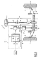
- a set of steering 1 of motor vehicle assisted electrically which comprises a steering wheel 2 integral with a first section 3 of a steering shaft 4, via a link 6.
- the steering shaft 4 transmits the torque applied on the steering wheel 2 by the driver of the vehicle to a transmission pinion 7, which meshes with a rack 8 arranged transversely to the axis of the vehicle between two steered wheels 9.
- Transmission pinion 7 could be replaced by any other body of transmission, such as a worm.
- Each steering wheel 9 is capable of pivoting about an axis Z-Z vertical pivoting under the effect of a displacement linear rack 8, said steering wheel 9 being actuated by an orientation mechanism comprising the rack and a connecting rod 10 connected to one end 11 of the rack 8.
- the steering assembly 1 also includes a assistance device 12 for exercising on the rack 8 an effort in the same sense as the effort exerted by the transmission pinion 7, so as to facilitate actuation of the steering wheel 2 by the driver of the vehicle, function of at least two operating parameters P1, P2 management, or more generally operating and / or condition of the vehicle.
- the assistance device 12 comprises an electric motor 15 whose output torque C s is controlled by an electronic control device 16 which delivers to the engine an assistance torque setpoint C.
- the output torque C s of the electric motor 15 is transmitted to a gearbox 19 via the output shaft 18 of the motor 15, and to an assist gear 20 meshing with the rack 8.
- the output shaft 18 of the electric motor 15 is mechanically connected to the steering shaft 4, by through the gearbox 19, the assist pinion 20, of the rack 8 and the transmission pinion 7.
- the mechanical connection of the output shaft 18 and the shaft of direction 4 could be different, especially more direct by not involving the rack 8.
- the output shaft 18 of the electric motor provides steering assistance of the steering wheel 2 by exerting on the steering shaft 4, via the mechanical elements mentioned above, an assist torque directly dependent on the output torque C s , and therefore the assist torque setpoint C.
- the first parameter P 1 is significant steering torque, that is to say the torque applied to the steering wheel 2 by the driver and / or suffered by the latter.
- the steering wheel torque is for example estimated by means of a torque sensor 21, mounted on the second section 5 of the steering shaft 4, in a region close to the pinion 7.
- This parameter is indicative of steering wheel holding conditions. , but also vibratory phenomena originating in the ground connection, and transmitted to the driver via the wheels, rods, the rack and the steering column.
- the second parameter P 2 is for example significant of the speed value of the vehicle. This is determined by conventional means for measuring the speed of advance, usually present on the vehicles, which will be designated by a speed sensor 22.
- the electronic control device 16 comprises basically a calculator 30 with two inputs and a output, and a signal processing circuit 31.
- the circuit 31 is connected to the output of the flywheel torque sensor 21, so as to receive as input a signal representative of the parameter P 1 of torque-flywheel, and its output is connected to the first input of the computer 30.
- the circuit 31 is represented by its transfer function H (f), where f is the frequency of the input signal representative of P 1 . This transfer function will be specified later.
- the computer 30 receives on its first input a signal representative of the parameter P 1 of the steering wheel torque, transformed in accordance with the transfer function H (f) of the circuit 31.
- the computer 30 is, on the other hand, inputly connected to the speed sensor 22, so that the second input of the computer 30 is powered by the signal representative of the vehicle speed parameter P 2 .
- the computer 30 is programmed to execute pre-recorded control laws, for example in the form cartographies, and to output a signal representative of the set torque value C, depending on the two input values.
- the output of the computer 30 is connected to the motor 15 in order to him deliver this control signal, representative of the value setpoint torque thus calculated.
- the calculator 30 and the laws of order associated with it may be provided for operate with a number of higher input parameters two, especially three input values.
- the calculation of the set torque can then take account for another operating and / or state parameter of the vehicle, such as a significant speed parameter rotation of the steering wheel.
- the objectives of the invention were translated by a target operating domain in which to locate the characteristic curve of the transfer function T (f).
- the transfer function thus defined modifies the gain and phase of transfer Link forces (input) to the couple-steering wheel (exit).
- these areas have been delineated for the gain and for the phase of the transfer function, respectively.
- the first frequency range has been limited to the interval [1 Hz, 10 Hz], and the second been limited to the interval [10 Hz, 20 Hz], these intervals being considered the most important in the context of the invention.
- the transfer function H (f) associated with the circuit 31 could advantageously be of the following form: where n is an integer ⁇ 3, and where the coefficients a i and b i are chosen for each type of vehicle, and for each set of values defining the desired operating domains, namely S, G 1 , G 2 , P, ⁇ 1 , and ⁇ 2 .
- the invention can be adapted to a large number of existing power steering systems.
Landscapes
- Engineering & Computer Science (AREA)
- Chemical & Material Sciences (AREA)
- Combustion & Propulsion (AREA)
- Transportation (AREA)
- Mechanical Engineering (AREA)
- Steering Control In Accordance With Driving Conditions (AREA)
- Power Steering Mechanism (AREA)
Abstract
Description
La présente invention se rapporte à un dispositif d'assistance électrique de direction de véhicule automobile.The present invention relates to a device electric steering assistance of a motor vehicle.
Elle concerne plus précisément un dispositif comprenant :
- un moteur électrique dont l'arbre de sortie est destiné à être relié à l'arbre de direction du véhicule, de façon à fournir une assistance au braquage du volant en exerçant sur l'arbre de direction un couple d'assistance, un effort de braquage résultant étant transmis à des roues directrices par l'intermédiaire d'un mécanisme d'orientation,
- un premier capteur mesurant un premier paramètre de fonctionnement du véhicule, significatif du couple-volant appliqué sur l'arbre de direction,
- un deuxième capteur mesurant un deuxième paramètre de fonctionnement et/ou d'état du véhicule, et
- un organe de calcul ayant au moins une première et une deuxième entrées, reliées respectivement au premier et au deuxième capteurs, et ayant une sortie reliée au moteur électrique et délivrant à ce dernier un signal de consigne de couple d'assistance représentatif d'une valeur calculée en appliquant aux valeurs d'entrée des lois de commande pré-enresgistréés.
- an electric motor whose output shaft is intended to be connected to the steering shaft of the vehicle, so as to provide steering assistance of the steering wheel by exerting on the steering shaft an assisting torque, an effort of resultant deflection being transmitted to steering wheels via an orientation mechanism,
- a first sensor measuring a first operating parameter of the vehicle, significant of the steering wheel torque applied to the steering shaft,
- a second sensor measuring a second operating parameter and / or a state of the vehicle, and
- a computing device having at least a first and a second input, respectively connected to the first and second sensors, and having an output connected to the electric motor and delivering to the latter an assist torque setpoint signal representative of a value calculated by applying to the input values pre-recorded control laws.
On connaít dans l'état de la technique de tels dispositifs d'assistance, comprenant une boucle de régulation dont la variable de contrôle est constituée par le couple-volant. Les lois de commande pré-enregistrées dans l'organe de calcul sont prévues pour calculer la valeur de consigne de couple en fonction des valeurs des paramètres d'entrée, dont la valeur de couple-volant, filtrée ou non.It is known in the state of the art such assistive devices, including a loop of regulation whose control variable is constituted by the flying couple. The control laws pre-registered in the calculator are intended to calculate the value of torque setpoint according to the values of the parameters input, whose torque-flywheel value, filtered or not.
On a constaté que dans les dispositifs d'assistance connus, quel que soit le soin apporté à l'élaboration des lois de commande, les « retours d'information » de la chaussée et les « remontées de direction » n'étaient pas maítrisés.It has been found that in assistive devices known, regardless of the care taken in the preparation of control laws, the "feedback" from the roadway and the "steering lifts" were not controlled.
Par « retours d'information », on entend les sollicitations fréquentielles provenant de la route, transmises au conducteur par l'intermédiaire des roues et de la colonne de direction, qui permettent au conducteur de ressentir une perte d'adhérence ou une dégradation de la chaussée, et ainsi d'adapter son mode de conduite. Ces sollicitations, qu'il est souhaitable de transmettre au conducteur avec un niveau d'amplitude suffisant, ont des fréquences principalement estimées entre 0 et 10 Hz."Feedback" means the frequency solicitations from the road, transmitted to the driver via the wheels and the steering column, which allow the driver to feel a loss of adhesion or degradation of the pavement, and thus to adapt his driving style. These solicitations, which it is desirable to transmit to the driver with a sufficient amplitude level, have frequencies mainly estimated between 0 and 10 Hz.
Par « remontées de direction », on entend les sollicitations séquentielles constituant des perturbations inutiles pour le conducteur. Ces sollicitations, qui ont des fréquences principalement estimées entre 10 et 20 Hz, doivent être filtrées par l'ensemble de direction pour un agrément de conduit amélioré."Raises of direction" means the sequential solicitations constituting disturbances unnecessary for the driver. These solicitations, which have frequencies mainly estimated between 10 and 20 Hz, have to be filtered by the direction set for a Improved conduit approval.
Certaines études ont montré que les sollicitations fréquentielles cheminant par la colonne de direction, depuis les roues directrices jusqu'au conducteur, ne constituent pas des signaux d'amplitude significative lorsque leur fréquence est supérieure à 20 Hz, de sorte qu'elles ne sont pas perçues par le conducteur, et ne nécessitent pas de traitement particulier.Some studies have shown that solicitations frequentiaries traveling by the steering column, since the steering wheels up to the driver do not constitute signals of significant amplitude when their frequency is greater than 20 Hz, so they are not not perceived by the driver, and do not require particular treatment.
L'invention a pour but de remédier à l'inconvénient ci-dessus, c'est-à-dire de proposer un dispositif d'assistance tel qu'exposé précédemment, qui permette, à faible coût, un retour d'information par la colonne de direction, tout en éliminant ou en atténuant de façon drastique les remontées de direction.The object of the invention is to remedy the drawback above, that is to say to propose a device assistance as described above, which allows, in low cost, feedback from the column of direction while eliminating or attenuating drastically the steering lifts.
Cet objectif est atteint par le dispositif d'assistance conforme à l'invention, du fait qu'il comprend en outre des moyens pour atténuer, respectivement amplifier, de façon sélective, dans des plages de fréquence prédéterminées, les phénomènes vibratoires sur le couple-volant, lesdits moyens fonctionnant par traitement du signal transmis à la première entrée de l'organe de calcul.This goal is achieved by the device according to the invention, because it comprises in addition means for attenuating, respectively amplifying, selectively in frequency ranges predetermined, the vibratory phenomena on the couple-steering wheel, said means operating by treatment of the signal transmitted to the first input of the computing device.
Suivant d'autres caractéristiques du dispositif conforme à l'invention :
- lesdits moyens sont adaptés pour atténuer les phénomènes vibratoires sur le couple-volant dans des fréquences supérieures à une valeur de seuil prédéterminée ;
- ladite valeur de seuil est comprise entre 8 et 14 Hz, de préférence égale à 10 Hz ;
- lesdits moyens comprennent un circuit de
traitement de signal dont l'entrée est reliée au premier
capteur et la sortie est reliée à la première entrée de
l'organe de calcul, ledit circuit appliquant au signal
d'entrée représentatif de la valeur de couple-volant
mesurée, une fonction de transfert de la forme
où f est la fréquence, n est un entier supérieur ou égal à 3,

et dans laquelle les coefficients ai, bi sont choisis de telle façon que la fonction de transfert, ayant pour entrée l'effort résultant appliqué au mécanisme d'orientation et pour sortie le couple-volant, présente une courbe de Bode représentative suivant laquelle :- dans une plage de fréquence comprise entre 0 et ladite valeur de seuil, le gain varie avec la fréquence entre une valeur basse et une valeur haute de gain constantes,
- pour des fréquences supérieures à ladite valeur de seuil, le gain varie avec la fréquence, en restant inférieur à une valeur maximale variant elle-même linéairement avec la fréquence de façon décroissante, selon une pente prédéterminée, non nulle, à partir de ladite valeur haute ; et
- les coefficients ai, bi sont choisis de telle façon
que la fonction de transfert, ayant pour entrée l'effort
résultant appliqué au mécanisme d'orientation et pour sortie
le couple-volant, présente une courbe de Bode représentative
de phase suivant laquelle :
- dans la plage de fréquence comprise entre 0 et ladite valeur de seuil, la phase varie avec la fréquence entre une valeur basse de phase strictement inférieure à 0 et une valeur haute de phase, inférieure ou égale 0, de préférence nulle,
- pour des fréquences supérieures à ladite valeur de seuil, la phase reste inférieure à ladite valeur haute de phase.
- said means is adapted to attenuate the vibratory phenomena on the steering wheel torque in frequencies higher than a predetermined threshold value;
- said threshold value is between 8 and 14 Hz, preferably equal to 10 Hz;
- said means comprise a signal processing circuit whose input is connected to the first sensor and the output is connected to the first input of the computing device, said circuit applying to the input signal representative of the steering wheel torque value measured, a transfer function of the form where f is the frequency, n is an integer greater than or equal to 3,
and wherein the coefficients a i , b i are chosen such that the transfer function, having for input the resultant force applied to the steering mechanism and for output the steering wheel torque, presents a representative Bode curve according to which :- in a frequency range between 0 and said threshold value, the gain varies with the frequency between a constant low value and a constant high value,
- for frequencies higher than said threshold value, the gain varies with the frequency, remaining below a maximum value itself varying linearly with the frequency decreasingly, according to a predetermined, non-zero slope, from said high value ; and
- the coefficients a i , b i are chosen in such a way that the transfer function, having as input the resultant force applied to the steering mechanism and for output the steering wheel pair, presents a representative phase Bode curve according to which:
- in the frequency range between 0 and said threshold value, the phase varies with the frequency between a low phase value strictly less than 0 and a high value of phase, less than or equal to 0, preferably zero,
- for frequencies higher than said threshold value, the phase remains lower than said high phase value.
L'invention vise en outre un ensemble de direction de véhicule automobile, comprenant un arbre de direction, un dispositif d'assistance électrique tel que décrit précédemment, relié à l'arbre de direction de façon à fournir une assistance au braquage du volant en exerçant sur l'arbre de direction un couple d'assistance, un mécanisme d'orientation relié à l'arbre de direction et au dispositif d'assistance, et par l'intermédiaire duquel est transmis un effort résultant de braquage à des roues directrices.The invention is further directed to a steering assembly of a motor vehicle, comprising a steering shaft, a electric assist device as described previously connected to the steering shaft so as to provide steering assistance to the steering wheel by exerting the steering shaft a couple of assistance, a mechanism Orientation connected to the steering shaft and the device assistance, and through which a resulting steering effort at steering wheels.
L'invention vise enfin un véhicule automobile comportant un ensemble de direction tel que décrit précédemment.The invention finally relates to a motor vehicle having a steering assembly as described previously.
Un mode particulier de réalisation de l'invention va maintenant être décrit plus en détail, en référence aux dessins annexés, sur lesquels :
- la Figure 1 est une vue schématique d'un ensemble de direction de véhicule, comportant un dispositif d'assistance suivant l'invention ;
- la Figure 2 est un diagramme de Bode représentant le gain, de la fonction de transfert couple-volant/effort crémaillère, qui montre le domaine de fonctionnement-cible du dispositif conforme à l'invention, et un exemple de courbe caractéristique-cible située à l'intérieur de ce domaine ; et
- la Figure 3 est un diagramme analogue à celui de la Figure 2, représentant la phase de la même fonction de transfert.
- Figure 1 is a schematic view of a vehicle steering assembly, comprising an assistance device according to the invention;
- FIG. 2 is a Bode diagram representing the gain, of the transfer torque-flywheel / rack force function, which shows the target operating range of the device according to the invention, and an example of a characteristic-target curve located at inside this area; and
- Figure 3 is a diagram similar to that of Figure 2, showing the phase of the same transfer function.
Sur la Figure 1, on a représenté un ensemble de
direction 1 de véhicule automobile assisté électriquement,
qui comporte un volant 2 solidaire d'un premier tronçon 3
d'un arbre de direction 4, par l'intermédiaire d'une liaison
à cardan 6. L'arbre de direction 4 transmet le couple
appliqué sur le volant 2 par le conducteur du véhicule à un
pignon de transmission 7, qui engrène avec une crémaillère 8
disposée transversalement par rapport à l'axe du véhicule
entre deux roues directrices 9. Le pignon de transmission 7
pourrait être remplacé par tout autre organe de
transmission, comme par exemple une vis sans fin. Chaque
roue directrice 9 est susceptible de pivoter autour d'un axe
de pivotement vertical Z-Z sous l'effet d'un déplacement
linéaire de la crémaillère 8, ladite roue directrice 9 étant
actionnée par un mécanisme d'orientation comportant la
crémaillère et une biellette 10 reliée à une extrémité 11 de
la crémaillère 8.In Figure 1, there is shown a set of
steering 1 of motor vehicle assisted electrically,
which comprises a
L'ensemble de direction 1 comprend également un
dispositif d'assistance 12 destiné à exercer sur la
crémaillère 8 un effort de même sens que l'effort exercé par
le pignon de transmission 7, de façon à faciliter
l'actionnement du volant 2 par le conducteur du véhicule, en
fonction d'au moins deux paramètres P1, P2 de fonctionnement
de la direction, ou plus généralement de fonctionnement
et/ou d'état du véhicule. The steering assembly 1 also includes a
Le dispositif d'assistance 12 comprend un moteur
électrique 15 dont le couple de sortie Cs est commandé par
un dispositif électronique de commande 16 qui délivre au
moteur une consigne de couple d'assistance C. Le couple de
sortie Cs du moteur électrique 15 est transmis à un
réducteur 19 par l'intermédiaire de l'arbre de sortie 18 du
moteur 15, et à un pignon d'assistance 20 engrenant avec la
crémaillère 8.The
Ainsi, l'arbre de sortie 18 du moteur électrique 15
est relié mécaniquement à l'arbre de direction 4, par
l'intermédiaire du réducteur 19, du pignon d'assistance 20,
de la crémaillère 8 et du pignon de transmission 7. La
liaison mécanique de l'arbre de sortie 18 et de l'arbre de
direction 4 pourrait être différente, notamment plus directe
en n'impliquant pas la crémaillère 8.Thus, the
L'arbre de sortie 18 du moteur électrique fournit
une assistance au braquage du volant 2 en exerçant sur
l'arbre de direction 4, par l'intermédiaire des éléments
mécaniques cités précédemment, un couple d'assistance
dépendant directement du couple de sortie Cs, et par
conséquent de la consigne de couple d'assistance C.The
Le premier paramètre P1 est significatif du couple-volant,
c'est-à-dire du couple appliqué sur le volant 2 par
le conducteur et/ou subi par ce dernier. Le couple-volant
est par exemple estimé au moyen d'un capteur de couple 21,
monté sur le deuxième tronçon 5 de l'arbre de direction 4,
dans une région proche du pignon 7. Ce paramètre est
significatif de conditions de maintien du volant, mais
également des phénomènes vibratoires prenant naissance au
niveau de la liaison au sol, et transmis au conducteur via
les roues, les biellettes, la crémaillère et la colonne de
direction.The first parameter P 1 is significant steering torque, that is to say the torque applied to the
Le deuxième paramètre P2 est par exemple
significatif de la valeur de vitesse du véhicule. Celle-ci
est déterminée par des moyens classiques de mesure de la
vitesse d'avance, présents usuellement sur les véhicules,
que l'on désignera par un capteur de vitesse d'avance 22.The second parameter P 2 is for example significant of the speed value of the vehicle. This is determined by conventional means for measuring the speed of advance, usually present on the vehicles, which will be designated by a
Le dispositif électronique de commande 16 comprend
essentiellement un calculateur 30 à deux entrées et une
sortie, et un circuit de traitement de signal 31.The
Le circuit 31 est relié à la sortie du capteur de
couple-volant 21, de façon à recevoir en entrée un signal
représentatif du paramètre P1 de couple-volant, et sa sortie
est connectée à la première entrée du calculateur 30.The
Le circuit 31 est représenté par sa fonction de
transfert H (f), où f est la fréquence du signal d'entrée
représentatif de P1. Cette fonction de transfert sera
précisée ultérieurement.The
Ainsi, le calculateur 30 reçoit sur sa première
entrée un signal représentatif du paramètre P1 de couple-volant,
transformé conformément à la fonction de transfert
H(f) du circuit 31.Thus, the
Le calculateur 30 est d'autre part relié en entrée
au capteur de vitesse 22, de sorte que la deuxième entrée du
calculateur 30 est alimentée par le signal représentatif du
paramètre P2 de vitesse du véhicule.The
Le calculateur 30 est programmé pour exécuter des
lois de commande pré-enregistrées, par exemple sous la forme
de cartographies, et pour délivrer en sortie un signal
représentatif de la valeur de couple de consigne
d'assistance C, en fonction des deux valeurs d'entrée. La
sortie du calculateur 30 est reliée au moteur 15 afin de lui
délivrer ce signal de commande, représentatif de la valeur
de couple de consigne ainsi calculé.The
Naturellement, le calculateur 30 et les lois de
commande qui lui sont associées peuvent être prévus pour
fonctionner avec un nombre de paramètres d'entrée supérieurs
à deux, notamment trois valeurs d'entrée. Naturally, the
Le calcul du couple de consigne peut alors prendre en compte un autre paramètre de fonctionnement et/ou d'état du véhicule, tel qu'un paramètre significatif de la vitesse de rotation du volant.The calculation of the set torque can then take account for another operating and / or state parameter of the vehicle, such as a significant speed parameter rotation of the steering wheel.
On va à présent expliciter davantage la fonction de transfert H(f) et, en référence aux Figures 2 et 3, on illustrera les effets physiques du traitement du signal ainsi opéré sur le paramètre de couple-volant P1 à l'entrée du calculateur 30.The transfer function H (f) will now be further explained and, with reference to FIGS. 2 and 3, the physical effects of the signal processing thus operated on the flywheel torque parameter P 1 will be illustrated at the input of the calculator. 30.
Sur les Figures 2 et 3, on a en effet traduit graphiquement les objectifs de l'invention consistant à atténuer, respectivement amplifier, de façon analogue, dans des plages de fréquence prédéterminées, les phénomènes vibratoires sur le couple-volant.In Figures 2 and 3, we have indeed translated graphically the objectives of the invention consisting in attenuate, respectively amplify, in a similar way, in predetermined frequency ranges, the phenomena vibratory on the couple-steering wheel.
Comme indiqué précédemment, ces phénomènes
vibratoires « remontent » de la route vers le conducteur
par les biellettes 10, la crémaillère 8, la colonne de
direction 4 et le volant 2. L'effet vibratoire ressenti par
le conducteur peut être traduit, comme cela a été fait dans
le cadre de l'invention, par la fonction de transfert T(f)
égale au rapport des valeurs algébriques du couple-volant et
de l'effort appliqué par les roues directrices 9 sur la
crémaillère 8, via les biellettes 10. Cette fonction de
transfert est associée à un système mécanique transmettant
des vibrations entre une entrée -les roues- et une sortie -
le volant-.As indicated above, these phenomena
vibratory "back" from the road to the driver
by the
Les objectifs de l'invention ont été traduits par un domaine de fonctionnement-cible dans lequel doit se situer la courbe caractéristique de la fonction de transfert T(f). La fonction de transfert ainsi définie modifie le gain et la phase du transfert Efforts biellettes (entrée) vers le couple-volant (sortie). Sur les Figures 2 et 3, ces domaines ont été délimités pour le gain et pour la phase de la fonction de transfert, respectivement. The objectives of the invention were translated by a target operating domain in which to locate the characteristic curve of the transfer function T (f). The transfer function thus defined modifies the gain and phase of transfer Link forces (input) to the couple-steering wheel (exit). In Figures 2 and 3, these areas have been delineated for the gain and for the phase of the transfer function, respectively.
Pour l'un et l'autre des domaines de fonctionnement, en gain et en phase, on distingue deux plages de fréquence :
- la première comprise entre 0 et une valeur de
seuil S prédéterminée, comprise
entre 8 et 14 Hz, de préférence égale à 10 Hz (comme indiqué sur les Figures) ; - la deuxième correspondant à des fréquences supérieures à cette valeur de seuil S.
- the first between 0 and a predetermined threshold value S, between 8 and 14 Hz, preferably equal to 10 Hz (as shown in the figures);
- the second corresponding to frequencies higher than this threshold value S.
Sur les Figures, la première plage de fréquence a été limitée à l'intervalle [1 Hz, 10 Hz], et la deuxième a été limitée à l'intervalle [10 Hz, 20 Hz], ces intervalles étant estimés comme les plus importants dans le cadre de l'invention.In the figures, the first frequency range has been limited to the interval [1 Hz, 10 Hz], and the second been limited to the interval [10 Hz, 20 Hz], these intervals being considered the most important in the context of the invention.
Le domaine de fonctionnement en gain se situe :
- pour la première plage de fréquence [0,S], qui correspond principalement à une plage d'amplification : entre la ligne droite horizontale à gain constant G1, et la ligne droite horizontale à gain constant G2, où G1 est inférieur à G2, G1 étant la valeur basse de gain et G2 étant la valeur haute de gain ;
- pour la deuxième plage de fonctionnement, correspondant aux valeurs de fréquence supérieures à S et principalement à une plage d'atténuation : au-dessous d'une droite de pente (P) non nulle, négative, passant par le point de coordonnées (S, G2).
- for the first frequency range [0, S], which corresponds mainly to an amplification range: between the constant gain horizontal straight line G 1 , and the constant gain horizontal straight line G 2 , where G 1 is less than G 2 , G 1 being the low value of gain and G 2 being the high value of gain;
- for the second operating range, corresponding to the frequency values above S and mainly to an attenuation range: below a non-zero, negative slope line (P) passing through the coordinate point (S, G 2 ).
Concernant la phase de la fonction de transfert T (f), le domaine de fonctionnement est défini de la façon suivante :
- pour la première plage de fonctionnement [0,S] : le domaine de fonctionnement est compris entre les deux lignes horizontales à phase constante, correspondant respectivement à une valeur basse 1 et à une valeur haute 2, avec 1<2≤0. On prendra de préférence 2=0 et 1=-30° ;
- pour la deuxième plage de fonctionnement, correspondant aux valeurs de fréquence supérieures à S : le domaine de fonctionnement se situe au-dessous de la ligne droite horizontale à phase constante 2.
- for the first operating range [0, S]: the operating range is between the two constant-phase horizontal lines, respectively corresponding to a low value 1 and a high value 2 , with 1 < 2 ≤ 0. We will preferably take 2 = 0 and 1 = -30 °;
- for the second operating range, corresponding to the frequency values above S: the operating range is below the constant phase horizontal straight line 2 .
Pour obtenir les caractéristiques désirées de la
fonction de transfert T (f), c'est-à-dire pour que les
courbes de Bode caractéristiques de cette fonction de
transfert se situent à l'intérieur des domaines de
fonctionnement définis ci-dessus, il s'est avéré que la
fonction de transfert H(f) associée au circuit 31 pouvait
être avantageusement de la forme suivante :

Ces domaines de fonctionnement peuvent être définis pour plusieurs conditions-types. Les domaines de fonctionnement qui ont été représentés sur les Figures ont par exemple été définis pour un véhicule particulier, et pour une intensité d'efforts appliqués sur la crémaillère variant entre -50 daN et +50 daN, en condition de volant bloqué.These areas of operation can be defined for several standard conditions. The fields of functioning that have been represented in the Figures have for example been defined for a particular vehicle, and for an intensity of forces applied to the rack varying between -50 daN and +50 daN, in steering condition blocked.
Il est important de noter que la fonction d'atténuation-amplification des filtrage des vibrations transitant par la colonne de direction est réalisée par des moyens électroniques de traitement de signal agissant sur une variable de régulation, qui est ici le couple-volant. L'apport de ces moyens électroniques de traitement dans les dispositifs d'assistance électrique, et plus généralement dans les ensembles de direction existant actuellement, ne représente aucun surcoût significatif. En particulier, la fonction d'atténuation/amplification des vibrations par les moyens définis dans l'invention n'implique aucun moyen mécanique ou électromécanique additionnel.It is important to note that the function attenuation-amplification of vibration filtering passing through the steering column is carried out by electronic means of signal processing acting on a regulating variable, which is here the flying couple. The contribution of these electronic means of treatment in electric assist devices, and more generally in the existing management sets, do not represents no significant additional cost. In particular, function of attenuation / amplification of vibrations by means defined in the invention does not imply any means of mechanical or electromechanical additional.
En outre, l'invention peut être adaptée à un grand nombre de directions assistées électriques existantes.In addition, the invention can be adapted to a large number of existing power steering systems.
La fonction d'atténuation/amplification des vibrations transitant par la colonne de direction, dans les conditions exposées dans la description qui précède, permet d'atteindre un haut niveau de sécurité ainsi qu'un haut niveau d'agrément de conduite.The function of attenuation / amplification of vibrations passing through the steering column, in the conditions set out in the foregoing description, allows to achieve a high level of security as well as a high level of driving pleasure.
Claims (7)

et dans laquelle les coefficients ai, bi sont choisis de telle façon que la fonction de transfert (T(f)), ayant pour entrée l'effort résultant appliqué au mécanisme d'orientation (10, 11) et pour sortie le couple-volant, présente une courbe de Bode représentative suivant laquelle :
and wherein the coefficients a i , b i are chosen such that the transfer function (T (f)), having as input the resultant force applied to the orientation mechanism (10, 11) and for output the torque -flying, presents a representative Bode curve according to which:
Applications Claiming Priority (2)
| Application Number | Priority Date | Filing Date | Title |
|---|---|---|---|
| FR0402551A FR2867437B1 (en) | 2004-03-11 | 2004-03-11 | ELECTRIC MOTOR VEHICLE STEERING ASSISTANCE DEVICE, STEERING ASSEMBLY PROVIDED WITH SUCH A DEVICE AND MOTOR VEHICLE EQUIPPED WITH SUCH AN ASSEMBLY |
| FR0402551 | 2004-03-11 |
Publications (2)
| Publication Number | Publication Date |
|---|---|
| EP1574417A1 true EP1574417A1 (en) | 2005-09-14 |
| EP1574417B1 EP1574417B1 (en) | 2006-10-11 |
Family
ID=34814572
Family Applications (1)
| Application Number | Title | Priority Date | Filing Date |
|---|---|---|---|
| EP05290430A Expired - Lifetime EP1574417B1 (en) | 2004-03-11 | 2005-02-24 | Electric power steering apparatus for an automotive vehicle, steering assembly having such an apparatus and automotive vehicle equipped with such an assembly |
Country Status (5)
| Country | Link |
|---|---|
| EP (1) | EP1574417B1 (en) |
| AT (1) | ATE342190T1 (en) |
| DE (1) | DE602005000165T2 (en) |
| ES (1) | ES2275259T3 (en) |
| FR (1) | FR2867437B1 (en) |
Cited By (4)
| Publication number | Priority date | Publication date | Assignee | Title |
|---|---|---|---|---|
| FR2909963A1 (en) * | 2006-12-15 | 2008-06-20 | Peugeot Citroen Automobiles Sa | Steering system e.g. electrical power-assisted steering system, assisting method for motor vehicle, involves adapting parameterization of logic controller according to inputs of driver of motor vehicle and various life situation of vehicle |
| EP2028080A1 (en) * | 2007-08-23 | 2009-02-25 | Ford Global Technologies, LLC | Method for operating an electric power steering system, electronic control unit for an electric power steering system and electric power steering system |
| EP2030868A1 (en) * | 2007-08-28 | 2009-03-04 | Ford Global Technologies, LLC | Method for operating an electric power steering system, electronic control unit for an electric power steering system and electric power steering system |
| CN114802425A (en) * | 2022-05-09 | 2022-07-29 | 中国第一汽车股份有限公司 | Motor output torque determination method, device, equipment and storage medium |
Families Citing this family (5)
| Publication number | Priority date | Publication date | Assignee | Title |
|---|---|---|---|---|
| DE102008021856A1 (en) | 2008-05-02 | 2009-11-05 | Volkswagen Ag | Electromechanical servo steering system for controlling desired steering angle of wheels of vehicle, has adjusting unit for adjusting steering angle of wheels, where supplementary signal is provided dependent on effect of road on wheels |
| DE102010021634A1 (en) | 2010-05-26 | 2011-12-01 | Volkswagen Ag | Method for reducing oscillations in electromechanical steering system of motor car, involves detecting oscillation which can be reduced, and changing control parameter of control unit when oscillation is detected |
| DE102010025197B4 (en) | 2010-06-26 | 2021-01-07 | Volkswagen Ag | Method and device for filtering a setpoint signal |
| DE102014105088B4 (en) * | 2014-04-10 | 2024-05-16 | Dr. Ing. H.C. F. Porsche Aktiengesellschaft | Controller for an electromechanical steering system, steering system with such a controller and motor vehicle with such a steering system |
| JPWO2021029329A1 (en) | 2019-08-09 | 2021-02-18 |
Citations (4)
| Publication number | Priority date | Publication date | Assignee | Title |
|---|---|---|---|---|
| US5659473A (en) * | 1994-06-28 | 1997-08-19 | Honda Giken Kogyo Kabushiki Kaisha | Electric power steering system |
| EP1142746A2 (en) * | 2000-04-04 | 2001-10-10 | FERRARI S.p.A. | Vehicle steering assembly |
| US20030106736A1 (en) * | 1999-07-28 | 2003-06-12 | Yoshinori Kogiso | Stable electric power steering system |
| FR2837161A1 (en) * | 2002-03-13 | 2003-09-19 | Soc Mecanique Irigny | METHOD FOR DAMPING THE PARASITIC VIBRATIONS ARISING FROM THE FRONT OF A MOTOR VEHICLE |
-
2004
- 2004-03-11 FR FR0402551A patent/FR2867437B1/en not_active Expired - Fee Related
-
2005
- 2005-02-24 DE DE602005000165T patent/DE602005000165T2/en not_active Expired - Lifetime
- 2005-02-24 EP EP05290430A patent/EP1574417B1/en not_active Expired - Lifetime
- 2005-02-24 AT AT05290430T patent/ATE342190T1/en not_active IP Right Cessation
- 2005-02-24 ES ES05290430T patent/ES2275259T3/en not_active Expired - Lifetime
Patent Citations (4)
| Publication number | Priority date | Publication date | Assignee | Title |
|---|---|---|---|---|
| US5659473A (en) * | 1994-06-28 | 1997-08-19 | Honda Giken Kogyo Kabushiki Kaisha | Electric power steering system |
| US20030106736A1 (en) * | 1999-07-28 | 2003-06-12 | Yoshinori Kogiso | Stable electric power steering system |
| EP1142746A2 (en) * | 2000-04-04 | 2001-10-10 | FERRARI S.p.A. | Vehicle steering assembly |
| FR2837161A1 (en) * | 2002-03-13 | 2003-09-19 | Soc Mecanique Irigny | METHOD FOR DAMPING THE PARASITIC VIBRATIONS ARISING FROM THE FRONT OF A MOTOR VEHICLE |
Cited By (4)
| Publication number | Priority date | Publication date | Assignee | Title |
|---|---|---|---|---|
| FR2909963A1 (en) * | 2006-12-15 | 2008-06-20 | Peugeot Citroen Automobiles Sa | Steering system e.g. electrical power-assisted steering system, assisting method for motor vehicle, involves adapting parameterization of logic controller according to inputs of driver of motor vehicle and various life situation of vehicle |
| EP2028080A1 (en) * | 2007-08-23 | 2009-02-25 | Ford Global Technologies, LLC | Method for operating an electric power steering system, electronic control unit for an electric power steering system and electric power steering system |
| EP2030868A1 (en) * | 2007-08-28 | 2009-03-04 | Ford Global Technologies, LLC | Method for operating an electric power steering system, electronic control unit for an electric power steering system and electric power steering system |
| CN114802425A (en) * | 2022-05-09 | 2022-07-29 | 中国第一汽车股份有限公司 | Motor output torque determination method, device, equipment and storage medium |
Also Published As
| Publication number | Publication date |
|---|---|
| EP1574417B1 (en) | 2006-10-11 |
| FR2867437B1 (en) | 2006-07-07 |
| DE602005000165T2 (en) | 2007-08-23 |
| FR2867437A1 (en) | 2005-09-16 |
| ES2275259T3 (en) | 2007-06-01 |
| DE602005000165D1 (en) | 2006-11-23 |
| ATE342190T1 (en) | 2006-11-15 |
Similar Documents
| Publication | Publication Date | Title |
|---|---|---|
| EP2018308B1 (en) | Electrical power steering system for a motor vehicle | |
| EP0598155B1 (en) | Turn controlling method and device for vehicle with non-steered wheels or tracks | |
| FR2660258A1 (en) | ELECTRIC VEHICLE WITH SPEED ADJUSTABLE WITH SAFETY. | |
| EP1574417B1 (en) | Electric power steering apparatus for an automotive vehicle, steering assembly having such an apparatus and automotive vehicle equipped with such an assembly | |
| FR2949421A1 (en) | TRACK CONTROL DEVICE FOR NARROW ELECTRIC MOTORIZED VEHICLE AND INCLINED TILT | |
| EP2181031B1 (en) | Power steering device for automobile | |
| EP1234747B1 (en) | Electric power steering for a vehicle and control method therefor | |
| WO2005119033A2 (en) | Method for controlling a set torque to be applied to wheels of an automatic transmission for a motor vehicle and corresponding device | |
| EP1446317B1 (en) | Electric power-steering assembly, and control method for same | |
| EP0556082A1 (en) | Hydraulic power steering with servo-controlled return mechanism and auxiliary control drive | |
| EP2145814B1 (en) | Method for toe-in adjustment of the front axle of an automobile | |
| EP1184259B1 (en) | Electric power steering assembly for motor vehicle | |
| EP1172280A1 (en) | Electric power steering assembly for a motor vehicle | |
| FR2821044A1 (en) | Electric power steering system for automotive vehicle, has control unit which compensates for effects on steering torque when braking in turns | |
| FR2821042A1 (en) | Power steering for motor vehicle has control of power steering motor dependent on braking parameters | |
| EP1655205B1 (en) | System and method of steering assistance for steerable wheels of a motor vehicle | |
| FR2821043A1 (en) | Power steering for motor vehicle has control of power steering motor dependent on braking parameters | |
| FR2861043A1 (en) | Motor vehicle, has calculation unit to calculate derivative of difference between measured and theoretical steering wheel angles, where driver accepts counter-lock of front wheel, if value of derivative remains lesser than threshold | |
| EP1029772A1 (en) | Control procedure and device for the assistance torque applied to the steering mechanism of a motor vehicle | |
| EP1926653B1 (en) | Method for controlling an electrical motor of a vehicle power steering device, and related power steering device | |
| EP1437289A1 (en) | Steering column for a motor vehicle, its control process and corresponding motor vehicle | |
| FR2972168A1 (en) | Decoupled steering control system i.e. steer-by-wire type control system, for controlling steering of wheels in e.g. front axle in car, has determination unit determining average maximum steering angle to be applied on wheels | |
| FR2908101A1 (en) | Force restoring device and manual control unit assembly for vehicle e.g. car, has force generator coupled to manual control unit, where assembly is arranged such that locking mechanism, generator and unit are coupled in series | |
| FR2972167A1 (en) | STEER-BY-WIRE TYPE STEERING SYSTEM FOR MOTOR VEHICLE | |
| FR2832376A1 (en) | Electric power steering for motor vehicle, has computers to determine power feed to steering servo motor dependant on operating parameters |
Legal Events
| Date | Code | Title | Description |
|---|---|---|---|
| PUAI | Public reference made under article 153(3) epc to a published international application that has entered the european phase |
Free format text: ORIGINAL CODE: 0009012 |
|
| AK | Designated contracting states |
Kind code of ref document: A1 Designated state(s): AT BE BG CH CY CZ DE DK EE ES FI FR GB GR HU IE IS IT LI LT LU MC NL PL PT RO SE SI SK TR |
|
| AX | Request for extension of the european patent |
Extension state: AL BA HR LV MK YU |
|
| GRAP | Despatch of communication of intention to grant a patent |
Free format text: ORIGINAL CODE: EPIDOSNIGR1 |
|
| 17P | Request for examination filed |
Effective date: 20060227 |
|
| AKX | Designation fees paid |
Designated state(s): AT BE BG CH CY CZ DE DK EE ES FI FR GB GR HU IE IS IT LI LT LU MC NL PL PT RO SE SI SK TR |
|
| GRAS | Grant fee paid |
Free format text: ORIGINAL CODE: EPIDOSNIGR3 |
|
| GRAA | (expected) grant |
Free format text: ORIGINAL CODE: 0009210 |
|
| AK | Designated contracting states |
Kind code of ref document: B1 Designated state(s): AT BE BG CH CY CZ DE DK EE ES FI FR GB GR HU IE IS IT LI LT LU MC NL PL PT RO SE SI SK TR |
|
| PG25 | Lapsed in a contracting state [announced via postgrant information from national office to epo] |
Ref country code: AT Free format text: LAPSE BECAUSE OF FAILURE TO SUBMIT A TRANSLATION OF THE DESCRIPTION OR TO PAY THE FEE WITHIN THE PRESCRIBED TIME-LIMIT Effective date: 20061011 Ref country code: IT Free format text: LAPSE BECAUSE OF FAILURE TO SUBMIT A TRANSLATION OF THE DESCRIPTION OR TO PAY THE FEE WITHIN THE PRESCRIBED TIME-LIMIT;WARNING: LAPSES OF ITALIAN PATENTS WITH EFFECTIVE DATE BEFORE 2007 MAY HAVE OCCURRED AT ANY TIME BEFORE 2007. THE CORRECT EFFECTIVE DATE MAY BE DIFFERENT FROM THE ONE RECORDED. Effective date: 20061011 Ref country code: LT Free format text: LAPSE BECAUSE OF FAILURE TO SUBMIT A TRANSLATION OF THE DESCRIPTION OR TO PAY THE FEE WITHIN THE PRESCRIBED TIME-LIMIT Effective date: 20061011 Ref country code: NL Free format text: LAPSE BECAUSE OF FAILURE TO SUBMIT A TRANSLATION OF THE DESCRIPTION OR TO PAY THE FEE WITHIN THE PRESCRIBED TIME-LIMIT Effective date: 20061011 Ref country code: PL Free format text: LAPSE BECAUSE OF FAILURE TO SUBMIT A TRANSLATION OF THE DESCRIPTION OR TO PAY THE FEE WITHIN THE PRESCRIBED TIME-LIMIT Effective date: 20061011 Ref country code: CZ Free format text: LAPSE BECAUSE OF FAILURE TO SUBMIT A TRANSLATION OF THE DESCRIPTION OR TO PAY THE FEE WITHIN THE PRESCRIBED TIME-LIMIT Effective date: 20061011 Ref country code: SK Free format text: LAPSE BECAUSE OF FAILURE TO SUBMIT A TRANSLATION OF THE DESCRIPTION OR TO PAY THE FEE WITHIN THE PRESCRIBED TIME-LIMIT Effective date: 20061011 Ref country code: RO Free format text: LAPSE BECAUSE OF FAILURE TO SUBMIT A TRANSLATION OF THE DESCRIPTION OR TO PAY THE FEE WITHIN THE PRESCRIBED TIME-LIMIT Effective date: 20061011 Ref country code: IE Free format text: LAPSE BECAUSE OF FAILURE TO SUBMIT A TRANSLATION OF THE DESCRIPTION OR TO PAY THE FEE WITHIN THE PRESCRIBED TIME-LIMIT Effective date: 20061011 Ref country code: FI Free format text: LAPSE BECAUSE OF FAILURE TO SUBMIT A TRANSLATION OF THE DESCRIPTION OR TO PAY THE FEE WITHIN THE PRESCRIBED TIME-LIMIT Effective date: 20061011 Ref country code: SI Free format text: LAPSE BECAUSE OF FAILURE TO SUBMIT A TRANSLATION OF THE DESCRIPTION OR TO PAY THE FEE WITHIN THE PRESCRIBED TIME-LIMIT Effective date: 20061011 |
|
| REG | Reference to a national code |
Ref country code: GB Ref legal event code: FG4D Free format text: NOT ENGLISH |
|
| REG | Reference to a national code |
Ref country code: CH Ref legal event code: EP |
|
| GBT | Gb: translation of ep patent filed (gb section 77(6)(a)/1977) |
Effective date: 20061011 |
|
| REG | Reference to a national code |
Ref country code: IE Ref legal event code: FG4D Free format text: LANGUAGE OF EP DOCUMENT: FRENCH |
|
| REF | Corresponds to: |
Ref document number: 602005000165 Country of ref document: DE Date of ref document: 20061123 Kind code of ref document: P |
|
| PG25 | Lapsed in a contracting state [announced via postgrant information from national office to epo] |
Ref country code: BG Free format text: LAPSE BECAUSE OF FAILURE TO SUBMIT A TRANSLATION OF THE DESCRIPTION OR TO PAY THE FEE WITHIN THE PRESCRIBED TIME-LIMIT Effective date: 20070111 Ref country code: DK Free format text: LAPSE BECAUSE OF FAILURE TO SUBMIT A TRANSLATION OF THE DESCRIPTION OR TO PAY THE FEE WITHIN THE PRESCRIBED TIME-LIMIT Effective date: 20070111 Ref country code: SE Free format text: LAPSE BECAUSE OF FAILURE TO SUBMIT A TRANSLATION OF THE DESCRIPTION OR TO PAY THE FEE WITHIN THE PRESCRIBED TIME-LIMIT Effective date: 20070111 |
|
| PG25 | Lapsed in a contracting state [announced via postgrant information from national office to epo] |
Ref country code: IS Free format text: LAPSE BECAUSE OF FAILURE TO SUBMIT A TRANSLATION OF THE DESCRIPTION OR TO PAY THE FEE WITHIN THE PRESCRIBED TIME-LIMIT Effective date: 20070211 |
|
| PG25 | Lapsed in a contracting state [announced via postgrant information from national office to epo] |
Ref country code: MC Free format text: LAPSE BECAUSE OF NON-PAYMENT OF DUE FEES Effective date: 20070228 |
|
| PG25 | Lapsed in a contracting state [announced via postgrant information from national office to epo] |
Ref country code: PT Free format text: LAPSE BECAUSE OF FAILURE TO SUBMIT A TRANSLATION OF THE DESCRIPTION OR TO PAY THE FEE WITHIN THE PRESCRIBED TIME-LIMIT Effective date: 20070319 |
|
| NLV1 | Nl: lapsed or annulled due to failure to fulfill the requirements of art. 29p and 29m of the patents act | ||
| REG | Reference to a national code |
Ref country code: IE Ref legal event code: FD4D |
|
| REG | Reference to a national code |
Ref country code: ES Ref legal event code: FG2A Ref document number: 2275259 Country of ref document: ES Kind code of ref document: T3 |
|
| PLBE | No opposition filed within time limit |
Free format text: ORIGINAL CODE: 0009261 |
|
| STAA | Information on the status of an ep patent application or granted ep patent |
Free format text: STATUS: NO OPPOSITION FILED WITHIN TIME LIMIT |
|
| 26N | No opposition filed |
Effective date: 20070712 |
|
| BERE | Be: lapsed |
Owner name: PEUGEOT CITROEN AUTOMOBILES S.A. Effective date: 20070228 |
|
| PG25 | Lapsed in a contracting state [announced via postgrant information from national office to epo] |
Ref country code: BE Free format text: LAPSE BECAUSE OF NON-PAYMENT OF DUE FEES Effective date: 20070228 |
|
| REG | Reference to a national code |
Ref country code: GB Ref legal event code: 746 Effective date: 20080329 |
|
| PG25 | Lapsed in a contracting state [announced via postgrant information from national office to epo] |
Ref country code: GR Free format text: LAPSE BECAUSE OF FAILURE TO SUBMIT A TRANSLATION OF THE DESCRIPTION OR TO PAY THE FEE WITHIN THE PRESCRIBED TIME-LIMIT Effective date: 20070112 |
|
| PG25 | Lapsed in a contracting state [announced via postgrant information from national office to epo] |
Ref country code: EE Free format text: LAPSE BECAUSE OF FAILURE TO SUBMIT A TRANSLATION OF THE DESCRIPTION OR TO PAY THE FEE WITHIN THE PRESCRIBED TIME-LIMIT Effective date: 20061011 |
|
| PGRI | Patent reinstated in contracting state [announced from national office to epo] |
Ref country code: IT Effective date: 20090401 |
|
| PG25 | Lapsed in a contracting state [announced via postgrant information from national office to epo] |
Ref country code: LU Free format text: LAPSE BECAUSE OF NON-PAYMENT OF DUE FEES Effective date: 20070224 Ref country code: CY Free format text: LAPSE BECAUSE OF FAILURE TO SUBMIT A TRANSLATION OF THE DESCRIPTION OR TO PAY THE FEE WITHIN THE PRESCRIBED TIME-LIMIT Effective date: 20061011 |
|
| PG25 | Lapsed in a contracting state [announced via postgrant information from national office to epo] |
Ref country code: TR Free format text: LAPSE BECAUSE OF FAILURE TO SUBMIT A TRANSLATION OF THE DESCRIPTION OR TO PAY THE FEE WITHIN THE PRESCRIBED TIME-LIMIT Effective date: 20061011 Ref country code: HU Free format text: LAPSE BECAUSE OF FAILURE TO SUBMIT A TRANSLATION OF THE DESCRIPTION OR TO PAY THE FEE WITHIN THE PRESCRIBED TIME-LIMIT Effective date: 20070412 |
|
| REG | Reference to a national code |
Ref country code: CH Ref legal event code: PL |
|
| PG25 | Lapsed in a contracting state [announced via postgrant information from national office to epo] |
Ref country code: LI Free format text: LAPSE BECAUSE OF NON-PAYMENT OF DUE FEES Effective date: 20090228 Ref country code: CH Free format text: LAPSE BECAUSE OF NON-PAYMENT OF DUE FEES Effective date: 20090228 |
|
| PGFP | Annual fee paid to national office [announced via postgrant information from national office to epo] |
Ref country code: ES Payment date: 20100125 Year of fee payment: 6 |
|
| PGFP | Annual fee paid to national office [announced via postgrant information from national office to epo] |
Ref country code: IT Payment date: 20100217 Year of fee payment: 6 |
|
| PG25 | Lapsed in a contracting state [announced via postgrant information from national office to epo] |
Ref country code: IT Free format text: LAPSE BECAUSE OF NON-PAYMENT OF DUE FEES Effective date: 20110224 |
|
| REG | Reference to a national code |
Ref country code: ES Ref legal event code: FD2A Effective date: 20120411 |
|
| PG25 | Lapsed in a contracting state [announced via postgrant information from national office to epo] |
Ref country code: ES Free format text: LAPSE BECAUSE OF NON-PAYMENT OF DUE FEES Effective date: 20110225 |
|
| PGFP | Annual fee paid to national office [announced via postgrant information from national office to epo] |
Ref country code: GB Payment date: 20140127 Year of fee payment: 10 |
|
| GBPC | Gb: european patent ceased through non-payment of renewal fee |
Effective date: 20150224 |
|
| REG | Reference to a national code |
Ref country code: FR Ref legal event code: PLFP Year of fee payment: 12 |
|
| PG25 | Lapsed in a contracting state [announced via postgrant information from national office to epo] |
Ref country code: GB Free format text: LAPSE BECAUSE OF NON-PAYMENT OF DUE FEES Effective date: 20150224 |
|
| PGFP | Annual fee paid to national office [announced via postgrant information from national office to epo] |
Ref country code: DE Payment date: 20160121 Year of fee payment: 12 |
|
| REG | Reference to a national code |
Ref country code: FR Ref legal event code: PLFP Year of fee payment: 13 |
|
| REG | Reference to a national code |
Ref country code: DE Ref legal event code: R119 Ref document number: 602005000165 Country of ref document: DE |
|
| REG | Reference to a national code |
Ref country code: FR Ref legal event code: PLFP Year of fee payment: 14 |
|
| PG25 | Lapsed in a contracting state [announced via postgrant information from national office to epo] |
Ref country code: DE Free format text: LAPSE BECAUSE OF NON-PAYMENT OF DUE FEES Effective date: 20170901 |
|
| REG | Reference to a national code |
Ref country code: FR Ref legal event code: CA Effective date: 20180312 Ref country code: FR Ref legal event code: CD Owner name: PEUGEOT CITROEN AUTOMOBILES SA, FR Effective date: 20180312 |
|
| PGFP | Annual fee paid to national office [announced via postgrant information from national office to epo] |
Ref country code: FR Payment date: 20220119 Year of fee payment: 18 |
|
| PG25 | Lapsed in a contracting state [announced via postgrant information from national office to epo] |
Ref country code: FR Free format text: LAPSE BECAUSE OF NON-PAYMENT OF DUE FEES Effective date: 20230228 |