EP1574366A1 - Achsaufhängung und Federplatte für eine Achsanbindung - Google Patents
Achsaufhängung und Federplatte für eine Achsanbindung Download PDFInfo
- Publication number
- EP1574366A1 EP1574366A1 EP05003809A EP05003809A EP1574366A1 EP 1574366 A1 EP1574366 A1 EP 1574366A1 EP 05003809 A EP05003809 A EP 05003809A EP 05003809 A EP05003809 A EP 05003809A EP 1574366 A1 EP1574366 A1 EP 1574366A1
- Authority
- EP
- European Patent Office
- Prior art keywords
- axle
- spring
- axle body
- control
- spring plate
- Prior art date
- Legal status (The legal status is an assumption and is not a legal conclusion. Google has not performed a legal analysis and makes no representation as to the accuracy of the status listed.)
- Granted
Links
Images

Classifications
-
- B—PERFORMING OPERATIONS; TRANSPORTING
- B60—VEHICLES IN GENERAL
- B60G—VEHICLE SUSPENSION ARRANGEMENTS
- B60G7/00—Pivoted suspension arms; Accessories thereof
- B60G7/001—Suspension arms, e.g. constructional features
-
- B—PERFORMING OPERATIONS; TRANSPORTING
- B60—VEHICLES IN GENERAL
- B60G—VEHICLE SUSPENSION ARRANGEMENTS
- B60G11/00—Resilient suspensions characterised by arrangement, location or kind of springs
- B60G11/02—Resilient suspensions characterised by arrangement, location or kind of springs having leaf springs only
- B60G11/10—Resilient suspensions characterised by arrangement, location or kind of springs having leaf springs only characterised by means specially adapted for attaching the spring to axle or sprung part of the vehicle
- B60G11/113—Mountings on the axle
-
- B—PERFORMING OPERATIONS; TRANSPORTING
- B60—VEHICLES IN GENERAL
- B60G—VEHICLE SUSPENSION ARRANGEMENTS
- B60G11/00—Resilient suspensions characterised by arrangement, location or kind of springs
- B60G11/32—Resilient suspensions characterised by arrangement, location or kind of springs having springs of different kinds
- B60G11/34—Resilient suspensions characterised by arrangement, location or kind of springs having springs of different kinds including leaf springs
- B60G11/46—Resilient suspensions characterised by arrangement, location or kind of springs having springs of different kinds including leaf springs and also fluid springs
- B60G11/465—Resilient suspensions characterised by arrangement, location or kind of springs having springs of different kinds including leaf springs and also fluid springs with a flexible wall
-
- B—PERFORMING OPERATIONS; TRANSPORTING
- B60—VEHICLES IN GENERAL
- B60G—VEHICLE SUSPENSION ARRANGEMENTS
- B60G9/00—Resilient suspensions of a rigid axle or axle housing for two or more wheels
- B60G9/003—Resilient suspensions of a rigid axle or axle housing for two or more wheels the axle being rigidly connected to a trailing guiding device
-
- B—PERFORMING OPERATIONS; TRANSPORTING
- B60—VEHICLES IN GENERAL
- B60G—VEHICLE SUSPENSION ARRANGEMENTS
- B60G2200/00—Indexing codes relating to suspension types
- B60G2200/30—Rigid axle suspensions
- B60G2200/31—Rigid axle suspensions with two trailing arms rigidly connected to the axle
-
- B—PERFORMING OPERATIONS; TRANSPORTING
- B60—VEHICLES IN GENERAL
- B60G—VEHICLE SUSPENSION ARRANGEMENTS
- B60G2202/00—Indexing codes relating to the type of spring, damper or actuator
- B60G2202/10—Type of spring
- B60G2202/11—Leaf spring
- B60G2202/112—Leaf spring longitudinally arranged
-
- B—PERFORMING OPERATIONS; TRANSPORTING
- B60—VEHICLES IN GENERAL
- B60G—VEHICLE SUSPENSION ARRANGEMENTS
- B60G2202/00—Indexing codes relating to the type of spring, damper or actuator
- B60G2202/10—Type of spring
- B60G2202/15—Fluid spring
- B60G2202/152—Pneumatic spring
-
- B—PERFORMING OPERATIONS; TRANSPORTING
- B60—VEHICLES IN GENERAL
- B60G—VEHICLE SUSPENSION ARRANGEMENTS
- B60G2204/00—Indexing codes related to suspensions per se or to auxiliary parts
- B60G2204/10—Mounting of suspension elements
- B60G2204/14—Mounting of suspension arms
- B60G2204/148—Mounting of suspension arms on the unsprung part of the vehicle, e.g. wheel knuckle or rigid axle
-
- B—PERFORMING OPERATIONS; TRANSPORTING
- B60—VEHICLES IN GENERAL
- B60G—VEHICLE SUSPENSION ARRANGEMENTS
- B60G2204/00—Indexing codes related to suspensions per se or to auxiliary parts
- B60G2204/40—Auxiliary suspension parts; Adjustment of suspensions
- B60G2204/43—Fittings, brackets or knuckles
- B60G2204/4306—Bracket or knuckle for rigid axles, e.g. for clamping
-
- B—PERFORMING OPERATIONS; TRANSPORTING
- B60—VEHICLES IN GENERAL
- B60G—VEHICLE SUSPENSION ARRANGEMENTS
- B60G2206/00—Indexing codes related to the manufacturing of suspensions: constructional features, the materials used, procedures or tools
- B60G2206/01—Constructional features of suspension elements, e.g. arms, dampers, springs
- B60G2206/10—Constructional features of arms
- B60G2206/11—Constructional features of arms the arm being a radius or track or torque or steering rod or stabiliser end link
-
- B—PERFORMING OPERATIONS; TRANSPORTING
- B60—VEHICLES IN GENERAL
- B60G—VEHICLE SUSPENSION ARRANGEMENTS
- B60G2206/00—Indexing codes related to the manufacturing of suspensions: constructional features, the materials used, procedures or tools
- B60G2206/01—Constructional features of suspension elements, e.g. arms, dampers, springs
- B60G2206/40—Constructional features of dampers and/or springs
- B60G2206/42—Springs
- B60G2206/428—Leaf springs
-
- B—PERFORMING OPERATIONS; TRANSPORTING
- B60—VEHICLES IN GENERAL
- B60G—VEHICLE SUSPENSION ARRANGEMENTS
- B60G2300/00—Indexing codes relating to the type of vehicle
- B60G2300/38—Low or lowerable bed vehicles
Definitions
- the present invention relates to an axle suspension for an air suspension vehicle axle with an axle body, the axle body at its two ends crossing handlebar springs and transverse to both the control springs as well as to the axle body extending, this Parts against each pulling pulling elements, on the one hand to the Axle body and on the other hand, facing away from the axle, from the outside opposite the Support the handlebar spring.
- the invention relates to an item of such axle suspension, namely a Spring plate for the support of tension elements, which the axle body of a Connect vehicle axle with a steering body spring crossing the axle body, wherein the Spring plate on the outside of the handlebar spring via front and rear support surfaces supported, which are located in front of or behind the axle body and each transverse to Extending pulling direction of the tension elements.
- the invention relates to another item of such axle suspension, namely a handlebar spring for supporting the axle body of an air-sprung Vehicle axle, with a front handlebar eye and arranged behind it Longitudinal section for the axis connection.
- axle suspensions, spring plates and control springs are known e.g. from DE 101 10 495 A1 known.
- This is a variety of variants for connecting the axle body the handlebar spring over straight or U-shaped tie rods disclosed.
- the maximum deflection of the air spring by the distance between the handlebar spring or at the top of the handlebar spring, in the area of the axle suspension arranged tie rods and the vehicle frame limited. With large deflection pivots the handlebar spring so far around its fixed pivot point in the console until it with the farthest from the pivot point of the axle suspension against the Vehicle frame abuts.
- the distance between the handlebar spring and vehicle frame has remained the same Vehicle height Influence on the loading volume of the vehicle, as by reducing this Distance can achieve a lowering of the cargo area, which on the other hand, the Loading height increases.
- the invention is therefore based on the object, one in the vertical direction and at to create a strong deflection as compact as possible axle suspension. Furthermore, should a spring plate and a handlebar spring are created, which build such a compact Enable axle suspension.
- the rear support surface is arranged lower than the front support surface.
- an axle suspension in which the tension elements are particularly advantageous Tie rods are located opposite the handlebar spring via specially designed spring plates support, which rest against the surface of the control spring and essentially extend transversely to the handlebar spring beyond its edge. That's the way it will be possible to change the axle body securely to its longitudinal cross section Tie handlebar spring, without drilling or the like, which the spring behavior of Impact the handlebar spring, enforce the handlebar spring.
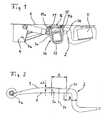
- Fig. 1 is an axle suspension in the case of maximum deflection of the air spring 5 or in the unpressurized state shown in a side view.
- the as a square tube Trained axle 1 is used for connection to the control arm 2 in the axle connection 14 held.
- the function of the vehicle trailing arm taking over the control arm spring 2 is provided at its front end with a handlebar eye 4a. This forms the fulcrum for the pivotal mounting of the handlebar spring 2 on the fixed console 4.
- the back end the control arm spring 2 is rigidly connected to the air spring 5, on the other hand opposite the vehicle frame 6 is supported.
- FIG. 2 the rolled spring steel of a spring steel spring 2 of the invention Axle suspension in a comparison with FIG. 1 slightly enlarged representation shown.
- the actual control arm spring 2 are also extending transversely to the control arm spring 2 Symmetrieebenen a front tension member 3a and a rear tension member 3b of Achsanitati 14 shown schematically, and further the center plane 1a of Axle body.
- the axle connection 14 extends over the longitudinal section A of the Trailing arm.
- the area B extends in the direction of the plane of symmetry of the axle body 2 at least half the width of the tension elements 3b beyond its plane of symmetry.
- the handlebar spring 2 rotates during compression from its substantially horizontal starting position only as long as the fixed pivot point 4a on the console 4 until it abuts with the rear fastening elements 3b on the vehicle frame.
- the height h 2 of the rear fastening elements 3 b thus determines the achievable pivot angle of the control arm spring 2 and thus ultimately the achievable deflection of the axle body.
- Fig. 3 is an enlarged section of the axle connection 14 shown in FIG. 1.
- the tension elements are tie rods 3a and 3b, which are transverse to the axle body 1 are connected via U-shaped sections to a bracket 12.
- Threaded sections are formed. These threaded sections are through Spring plates 11a, 11b inserted through, and the nuts 15 is a bracing the spring plate 11 against the surface 9 of the control arm spring 2.
- the spring plates 11a, 11b thereby extend transversely to the handlebar springs 2 to beyond the side edges.
- the front spring plate section 11 a is longitudinally in front of the axle body and the rear spring plate section 11b behind the axle body 1.
- At the bottom of the spring plate sections are each with Provided support surfaces 16 a and 16 b, with which they each on the top 9 of the Support the handlebar spring 2.
- Both support surfaces 16a, 16b are designed so that they transversely to the Pulling direction 17 of the tension elements 3a, 3b extend. In this way, the in the Tensile elements 3a, 3b acting tensile force at right angles and thus free of lateral forces on the Transfer top 9 of the handlebar spring.
- the bridge 13 connects the front spring plate portion 11a with the rear spring plate portion 11b, and therefore serves for additional stabilization of the force application points of the tie rods 3a, 3b.
- the web 13 is between the front, higher spring plate portion 11 a and the rear, lower-located spring plate portion 11b inclined sloping designed.
- the entire spring plate 16 including the two spring plate sections 11a, 11b and the Web 13 is made in one piece, preferably as a cast or forged part.
- the reduced overall height of the tension elements 3b by the difference ⁇ h which essentially corresponds to the reduction in the cross-sectional height of the control arm 2, reached.
- the tension elements 3b or 3a in each case substantially parallel to the axle body 1 and with the opposite Tension elements 3a and 3b via the substantially U-shaped bracket 12th integrally connected. For this reason, it is necessary that the Achslappen 10 am the lower end of the axle body 1 protrudes beyond this and forms recordings on which the tension elements 3a and 3b can support pressure-resistant.
- axle connection 14 in which, for example, the tension elements 3a, 3b are not integral brackets 12, but straight bolts, conceivable in which also the low height h 2 of the rear tension element 3b compared to the height h 1 of the front tension element 3a according to the invention serves to reduce the overall height of the entire axle suspension.
Landscapes
- Engineering & Computer Science (AREA)
- Mechanical Engineering (AREA)
- Vehicle Body Suspensions (AREA)
- Springs (AREA)
Abstract
Description
- Fig. 1:
- Prinzipdarstellung einer Achsaufhängung im Falle maximaler Einfederung der Luftfeder oder in deren drucklosem Zustand
- Fig. 2:
- Einzelteilzeichnung der Lenkerfeder einer Achsaufhängung
- Fig. 3:
- Vergrößerter Ausschnitt der Achsanbindung nach Fig. 1
- Fig. 4:
- Vergrößerter Ausschnitt der Achsanbindung bei einer alternativ gestalteten Achsaufhängung
- 1
- Achskörper
- 1a
- Mittellinie
- 2
- Lenkerfeder
- 3a
- Zugelement
- 3b
- Zugelement
- 4
- Konsole
- 4a
- Drehpunkt, Lenkerauge
- 5
- Luftfeder
- 6
- Fahrzeugrahmen
- 7
- Achsplatte
- 8
- Unterseite der Lenkerfeder
- 9
- Oberseite der Lenkerfeder
- 10
- Achslappen
- 11a
- Federplattenabschnitt
- 11b
- Federplattenabschnitt
- 12
- Bügel
- 13
- Steg
- 14
- Achsanbindung
- 15
- Mutter
- 16
- Federplatte
- 16a
- Stützfläche
- 16b
- Stützfläche
- 17
- Zugrichtung
- A
- Längsabschnitt
- B
- Bereich reduzierter Querschnittshöhe der Lenkerfeder
- h1
- Bauhöhe
- h2
- Bauhöhe
- Δh
- Höhendifferenz
Claims (10)
- Achsaufhängung für eine luftgefederte Fahrzeugachse mit einem Achskörper (1), den Achskörper (1) an seinen beiden Enden kreuzenden Lenkerfedern (2) sowie quer sowohl zu den Lenkerfedern (2) wie auch zu dem Achskörper (1) verlaufenden, diese Teile gegeneinander ziehenden Zugelementen (3a, 3b), die sich einerseits gegenüber dem Achskörper (1) und andererseits, dem Achskörper (1) abgewandt, von außen gegenüber der Lenkerfeder (2) abstützen,
dadurch gekennzeichnet, daß sich die Querschnittshöhe der Lenkerfeder (2) auf dem Längsabschnitt (A) der Achsanbindung (14) nach hinten hin reduziert, und daß die hinter dem Achskörper (1) angeordneten Zugelemente (3b) eine reduzierte Bauhöhe (h2) aufweisen. - Achsaufhängung nach Anspruch 1, dadurch gekennzeichnet, daß der Achskörper (1) unter der Lenkerfeder (2) angeordnet ist.
- Achsaufhängung nach einem der Ansprüche 1 oder 2, dadurch gekennzeichnet, daß Zugelemente (3a, 3b) Zugstangen sind, die sich gegenüber der Lenkerfeder (2) über mindestens eine Federplatte (11; 16) abstützen, die an der Oberfläche (9) der Lenkerfeder (2) anliegt und sich quer zur Lenkerfeder (2) bis über deren Rand hinaus erstreckt.
- Achsaufhängung nach Anspruch 3, dadurch gekennzeichnet, daß die Federplatten (11) jeweils über einen Steg (13), der im wesentlichen in Längsrichtung der Lenkerfeder (2) verläuft, miteinander verbunden sind.
- Achsaufhängung nach Anspruch 1, dadurch gekennzeichnet, daß jeweils zwei Zugstangen (3a, 3b) über Bügel (12) einstückig miteinander verbunden sind, die sich druckfest am Achskörper (1) abstützen.
- Federplatte für die Abstützung von Zugelementen, welche den Achskörper einer Fahrzeugachse mit einer den Achskörper kreuzenden Lenkerfeder verbinden, wobei sich die Federplatte (16) an der Außenseite der Lenkerfeder über vordere und hintere Stützflächen (16a, 16b) abstützt, die sich vor bzw. hinter dem Achskörper befinden und sich jeweils quer zur Zugrichtung der Zugelemente erstrecken,
dadurch gekennzeichnet, daß die hintere Stützfläche (16b) tiefer als die vordere Stützfläche (16a) angeordnet ist. - Federplatte nach Anspruch 6, dadurch gekennzeichnet, daß diese einen vorderen Federplattenabschnitt (11a), an dessen Unterseite die vordere Stützfläche (16a) ausgebildete ist, und einen hinteren Federplattenabschnitt (11b), an dessen Unterseite die hintere Stützfläche (16b) ausgebildet ist aufweist, und daß vorderer und hinterer Federplattenabschnitt (11a, 11b) in Lenkerfeder-Längsrichtung über einen Steg (13) miteinander verbunden sind.
- Federplatte nach Anspruch 7, dadurch gekennzeichnet, daß der Steg (13) zwischen dem vorderen Federplattenabschnitt (11a) und dem hinteren Federplattenabschnitt (11b) schräg abfallend gestaltet ist.
- Lenkerfeder zur Abstützung des Achskörpers einer luftgefederten Fahrzeugachse, mit einem vorderen Lenkerauge (4a) und einem dahinter angeordneten Längsabschnitt (A) für die Achsanbindung,
dadurch gekennzeichnet, daß sich die Querschnittshöhe der Lenkerfeder auf dem Längsabschnitt (A) der Achsanbindung nach hinten hin reduziert. - Lenkerfeder nach Anspruch 9, dadurch gekennzeichnet, daß die Querschnittsbreite der Lenkerfeder im Längsabschnitt (A) der Achsanbindung gleich bleibend ist.
Priority Applications (1)
| Application Number | Priority Date | Filing Date | Title |
|---|---|---|---|
| PL05003809T PL1574366T3 (pl) | 2004-03-09 | 2005-02-23 | Zawieszenie i sprężyna płytkowa dla zawieszenia osi |
Applications Claiming Priority (2)
| Application Number | Priority Date | Filing Date | Title |
|---|---|---|---|
| DE102004011292 | 2004-03-09 | ||
| DE102004011292A DE102004011292A1 (de) | 2004-03-09 | 2004-03-09 | Achsaufhängung und Federplatte für eine Achsanbindung |
Publications (2)
| Publication Number | Publication Date |
|---|---|
| EP1574366A1 true EP1574366A1 (de) | 2005-09-14 |
| EP1574366B1 EP1574366B1 (de) | 2006-08-30 |
Family
ID=34813619
Family Applications (1)
| Application Number | Title | Priority Date | Filing Date |
|---|---|---|---|
| EP05003809A Expired - Lifetime EP1574366B1 (de) | 2004-03-09 | 2005-02-23 | Achsaufhängung und Federplatte für eine Achsanbindung |
Country Status (5)
| Country | Link |
|---|---|
| EP (1) | EP1574366B1 (de) |
| AT (1) | ATE337925T1 (de) |
| DE (2) | DE102004011292A1 (de) |
| ES (1) | ES2271918T3 (de) |
| PL (1) | PL1574366T3 (de) |
Cited By (8)
| Publication number | Priority date | Publication date | Assignee | Title |
|---|---|---|---|---|
| EP1911613A1 (de) * | 2006-10-13 | 2008-04-16 | Goldschmitt techmobil AG | Achsaufhängung mit zwei Radführungsfedern |
| JP2010052521A (ja) * | 2008-08-27 | 2010-03-11 | Caterpillar Japan Ltd | アクスルケースの取付機構 |
| JP2010052520A (ja) * | 2008-08-27 | 2010-03-11 | Caterpillar Japan Ltd | アクスルケースの取付機構 |
| WO2010066232A1 (de) * | 2008-12-09 | 2010-06-17 | Bpw Bergische Achsen Kg | Achsaufhängung für eine fahrzeugachse |
| DE102009030633A1 (de) * | 2009-06-25 | 2010-12-30 | Bpw Bergische Achsen Kg | Achseinbindung für gefederte Fahrzeugachsen sowie Platte zum Einbinden einer Fahrzeugachse |
| CN103241083A (zh) * | 2013-04-28 | 2013-08-14 | 安徽华菱汽车有限公司 | 一种推力杆支座与一种悬架 |
| CN107351605A (zh) * | 2017-06-06 | 2017-11-17 | 郑州精益达汽车零部件有限公司 | 一种新型桥壳垫板总成 |
| US11767067B2 (en) | 2020-12-01 | 2023-09-26 | Volvo Truck Corporation | Joint for mounting an elongate element to a structural element in a vehicle |
Citations (7)
| Publication number | Priority date | Publication date | Assignee | Title |
|---|---|---|---|---|
| DE3148015A1 (de) * | 1981-12-04 | 1983-06-16 | Daimler-Benz Ag, 7000 Stuttgart | "luftgefederte starrachse fuer nutzfahrzeuge, insbesondere fuer lastkraftwagen" |
| DE4224965C1 (en) * | 1992-07-29 | 1993-08-05 | Bergische Achsenfabrik Fr. Kotz & Soehne, 5276 Wiehl, De | Square section air spring axle for trailer - uses spring clamps to hold axle in right angle formed in spring carrier arm. |
| EP1088687A1 (de) * | 1999-09-29 | 2001-04-04 | Weweler Nederland B.V. | Verbindung zwischen einer Radachse eines Fahrzeugs und einem die Radachse tragenden Tragarm |
| DE19946802A1 (de) * | 1999-09-29 | 2001-04-19 | Schmitz Cargobull Ag | Luftgefedertes Achssystem |
| DE10110495A1 (de) | 2001-03-05 | 2002-09-19 | Bpw Bergische Achsen Kg | Achseinbindung für gefederte Fahrzeugachsen |
| EP1273464A1 (de) * | 2001-07-02 | 2003-01-08 | Weweler Nederland B.V. | Verbindung zwischen einer starren Radachse eines Fahrzeugs und einem die Radachse tragenden Tragarm |
| EP1334848A1 (de) * | 2002-01-17 | 2003-08-13 | Schmitz Cargobull AG | Fahrzeugachsenelement mit Tragarm und damit verbundenem Achsrohr |
Family Cites Families (2)
| Publication number | Priority date | Publication date | Assignee | Title |
|---|---|---|---|---|
| DE3435251A1 (de) * | 1984-09-26 | 1986-04-03 | Böhler AG, 4000 Düsseldorf | Blattfeder |
| DE3527899A1 (de) * | 1985-08-03 | 1987-02-12 | Boehler Ag | Federung fuer fahrzeuge |
-
2004
- 2004-03-09 DE DE102004011292A patent/DE102004011292A1/de not_active Withdrawn
-
2005
- 2005-02-23 DE DE502005000075T patent/DE502005000075D1/de not_active Expired - Lifetime
- 2005-02-23 ES ES05003809T patent/ES2271918T3/es not_active Expired - Lifetime
- 2005-02-23 PL PL05003809T patent/PL1574366T3/pl unknown
- 2005-02-23 AT AT05003809T patent/ATE337925T1/de not_active IP Right Cessation
- 2005-02-23 EP EP05003809A patent/EP1574366B1/de not_active Expired - Lifetime
Patent Citations (7)
| Publication number | Priority date | Publication date | Assignee | Title |
|---|---|---|---|---|
| DE3148015A1 (de) * | 1981-12-04 | 1983-06-16 | Daimler-Benz Ag, 7000 Stuttgart | "luftgefederte starrachse fuer nutzfahrzeuge, insbesondere fuer lastkraftwagen" |
| DE4224965C1 (en) * | 1992-07-29 | 1993-08-05 | Bergische Achsenfabrik Fr. Kotz & Soehne, 5276 Wiehl, De | Square section air spring axle for trailer - uses spring clamps to hold axle in right angle formed in spring carrier arm. |
| EP1088687A1 (de) * | 1999-09-29 | 2001-04-04 | Weweler Nederland B.V. | Verbindung zwischen einer Radachse eines Fahrzeugs und einem die Radachse tragenden Tragarm |
| DE19946802A1 (de) * | 1999-09-29 | 2001-04-19 | Schmitz Cargobull Ag | Luftgefedertes Achssystem |
| DE10110495A1 (de) | 2001-03-05 | 2002-09-19 | Bpw Bergische Achsen Kg | Achseinbindung für gefederte Fahrzeugachsen |
| EP1273464A1 (de) * | 2001-07-02 | 2003-01-08 | Weweler Nederland B.V. | Verbindung zwischen einer starren Radachse eines Fahrzeugs und einem die Radachse tragenden Tragarm |
| EP1334848A1 (de) * | 2002-01-17 | 2003-08-13 | Schmitz Cargobull AG | Fahrzeugachsenelement mit Tragarm und damit verbundenem Achsrohr |
Cited By (10)
| Publication number | Priority date | Publication date | Assignee | Title |
|---|---|---|---|---|
| EP1911613A1 (de) * | 2006-10-13 | 2008-04-16 | Goldschmitt techmobil AG | Achsaufhängung mit zwei Radführungsfedern |
| JP2010052521A (ja) * | 2008-08-27 | 2010-03-11 | Caterpillar Japan Ltd | アクスルケースの取付機構 |
| JP2010052520A (ja) * | 2008-08-27 | 2010-03-11 | Caterpillar Japan Ltd | アクスルケースの取付機構 |
| WO2010066232A1 (de) * | 2008-12-09 | 2010-06-17 | Bpw Bergische Achsen Kg | Achsaufhängung für eine fahrzeugachse |
| EP2607115A1 (de) * | 2008-12-09 | 2013-06-26 | BPW Bergische Achsen KG | Achsaufhängung für eine Fahrzeugachse |
| CN102245411B (zh) * | 2008-12-09 | 2013-12-25 | Bpw矿用轴公司 | 用于车轴的轴悬挂装置 |
| DE102009030633A1 (de) * | 2009-06-25 | 2010-12-30 | Bpw Bergische Achsen Kg | Achseinbindung für gefederte Fahrzeugachsen sowie Platte zum Einbinden einer Fahrzeugachse |
| CN103241083A (zh) * | 2013-04-28 | 2013-08-14 | 安徽华菱汽车有限公司 | 一种推力杆支座与一种悬架 |
| CN107351605A (zh) * | 2017-06-06 | 2017-11-17 | 郑州精益达汽车零部件有限公司 | 一种新型桥壳垫板总成 |
| US11767067B2 (en) | 2020-12-01 | 2023-09-26 | Volvo Truck Corporation | Joint for mounting an elongate element to a structural element in a vehicle |
Also Published As
| Publication number | Publication date |
|---|---|
| EP1574366B1 (de) | 2006-08-30 |
| PL1574366T3 (pl) | 2007-01-31 |
| ES2271918T3 (es) | 2007-04-16 |
| ATE337925T1 (de) | 2006-09-15 |
| DE102004011292A1 (de) | 2005-09-22 |
| DE502005000075D1 (de) | 2006-10-12 |
Similar Documents
| Publication | Publication Date | Title |
|---|---|---|
| DE60118903T2 (de) | Blattfedereinrichtung mit ganzem blatt-blatt-federbauelement und halbem blatt-blatt-federbauelement | |
| DE60125410T2 (de) | Fahrzeugaufhängungssystem | |
| EP2355988B2 (de) | Achsaufhängung für eine fahrzeugachse | |
| EP0940272B1 (de) | Fahrgestell eines Frontlenker-Lastkraftwagen | |
| EP2540533B1 (de) | Radaufhängung für ein Fahrzeug | |
| DE4007634C2 (de) | ||
| EP1905683A1 (de) | Hinterradschwinge für ein Motorrad | |
| EP3871909A1 (de) | Lenkbare einzelradaufhängung mit zusätzlichem träger | |
| EP1574366B1 (de) | Achsaufhängung und Federplatte für eine Achsanbindung | |
| DE69225225T2 (de) | Fahrzeugaufhängung | |
| EP2780182B1 (de) | Starrachse mit luftfederung | |
| DE102008031775A1 (de) | Mehrpunktlenkeranordnung für einen Fahrzeugrahmen eines Nutzfahrzeuges sowie Trägerkonsole und Querträger für eine Mehrpunktlenkeranordnung | |
| EP0899133B1 (de) | Einzelradaufhängung einer Hinterachse | |
| DE102009030633A1 (de) | Achseinbindung für gefederte Fahrzeugachsen sowie Platte zum Einbinden einer Fahrzeugachse | |
| EP1057716B1 (de) | Achskonstruktion für Nutzfahrzeuge, Nutzfahrzeuganhänger und -auflieger | |
| DE10018315A1 (de) | Achsaufhängung für eine luftgefederte Fahrzeugachse | |
| DE102020105380A1 (de) | Lenkbare Einzelradaufhängung mit Federeinrichtung | |
| EP1777085B1 (de) | Achsaufhängung für eine längslenkergeführte Fahrzeugachse | |
| EP2163401B1 (de) | Achskörper für eine Fahrzeugachse, insbesondere für eine Starrachse eines Kraft- und/oder Nutzfahrzeuges | |
| DE102021116433B4 (de) | Anbauchassis und Straßenfahrzeug | |
| EP2647512B1 (de) | Achslenker | |
| DE69613478T2 (de) | Achsenkonstruktion für ein fahrzeug | |
| EP3098093A1 (de) | Zuggabel für ein anhängerfahrzeug | |
| EP3148824A1 (de) | Achsanordnung | |
| DE69001184T2 (de) | Stabilisatoreinrichtung, mit dieser ausgeruestetes kraftfahrzeug und teilesatz zum einbau derselben in ein solches fahrzeug. |
Legal Events
| Date | Code | Title | Description |
|---|---|---|---|
| PUAI | Public reference made under article 153(3) epc to a published international application that has entered the european phase |
Free format text: ORIGINAL CODE: 0009012 |
|
| AK | Designated contracting states |
Kind code of ref document: A1 Designated state(s): AT BE BG CH CY CZ DE DK EE ES FI FR GB GR HU IE IS IT LI LT LU MC NL PL PT RO SE SI SK TR |
|
| AX | Request for extension of the european patent |
Extension state: AL BA HR LV MK YU |
|
| 17P | Request for examination filed |
Effective date: 20060121 |
|
| GRAP | Despatch of communication of intention to grant a patent |
Free format text: ORIGINAL CODE: EPIDOSNIGR1 |
|
| AKX | Designation fees paid |
Designated state(s): AT BE BG CH CY CZ DE DK EE ES FI FR GB GR HU IE IS IT LI LT LU MC NL PL PT RO SE SI SK TR |
|
| GRAS | Grant fee paid |
Free format text: ORIGINAL CODE: EPIDOSNIGR3 |
|
| GRAA | (expected) grant |
Free format text: ORIGINAL CODE: 0009210 |
|
| AK | Designated contracting states |
Kind code of ref document: B1 Designated state(s): AT BE BG CH CY CZ DE DK EE ES FI FR GB GR HU IE IS IT LI LT LU MC NL PL PT RO SE SI SK TR |
|
| PG25 | Lapsed in a contracting state [announced via postgrant information from national office to epo] |
Ref country code: RO Free format text: LAPSE BECAUSE OF FAILURE TO SUBMIT A TRANSLATION OF THE DESCRIPTION OR TO PAY THE FEE WITHIN THE PRESCRIBED TIME-LIMIT Effective date: 20060830 Ref country code: IT Free format text: LAPSE BECAUSE OF FAILURE TO SUBMIT A TRANSLATION OF THE DESCRIPTION OR TO PAY THE FEE WITHIN THE PRESCRIBED TIME-LIMIT;WARNING: LAPSES OF ITALIAN PATENTS WITH EFFECTIVE DATE BEFORE 2007 MAY HAVE OCCURRED AT ANY TIME BEFORE 2007. THE CORRECT EFFECTIVE DATE MAY BE DIFFERENT FROM THE ONE RECORDED. Effective date: 20060830 Ref country code: IE Free format text: LAPSE BECAUSE OF FAILURE TO SUBMIT A TRANSLATION OF THE DESCRIPTION OR TO PAY THE FEE WITHIN THE PRESCRIBED TIME-LIMIT Effective date: 20060830 Ref country code: FI Free format text: LAPSE BECAUSE OF FAILURE TO SUBMIT A TRANSLATION OF THE DESCRIPTION OR TO PAY THE FEE WITHIN THE PRESCRIBED TIME-LIMIT Effective date: 20060830 Ref country code: LT Free format text: LAPSE BECAUSE OF FAILURE TO SUBMIT A TRANSLATION OF THE DESCRIPTION OR TO PAY THE FEE WITHIN THE PRESCRIBED TIME-LIMIT Effective date: 20060830 Ref country code: SK Free format text: LAPSE BECAUSE OF FAILURE TO SUBMIT A TRANSLATION OF THE DESCRIPTION OR TO PAY THE FEE WITHIN THE PRESCRIBED TIME-LIMIT Effective date: 20060830 Ref country code: SI Free format text: LAPSE BECAUSE OF FAILURE TO SUBMIT A TRANSLATION OF THE DESCRIPTION OR TO PAY THE FEE WITHIN THE PRESCRIBED TIME-LIMIT Effective date: 20060830 Ref country code: IS Free format text: LAPSE BECAUSE OF FAILURE TO SUBMIT A TRANSLATION OF THE DESCRIPTION OR TO PAY THE FEE WITHIN THE PRESCRIBED TIME-LIMIT Effective date: 20060830 |
|
| REG | Reference to a national code |
Ref country code: GB Ref legal event code: FG4D Free format text: NOT ENGLISH |
|
| REG | Reference to a national code |
Ref country code: CH Ref legal event code: EP |
|
| REG | Reference to a national code |
Ref country code: IE Ref legal event code: FG4D Free format text: LANGUAGE OF EP DOCUMENT: GERMAN |
|
| REF | Corresponds to: |
Ref document number: 502005000075 Country of ref document: DE Date of ref document: 20061012 Kind code of ref document: P |
|
| REG | Reference to a national code |
Ref country code: GR Ref legal event code: EP Ref document number: 20060403595 Country of ref document: GR |
|
| GBT | Gb: translation of ep patent filed (gb section 77(6)(a)/1977) |
Effective date: 20061106 |
|
| PG25 | Lapsed in a contracting state [announced via postgrant information from national office to epo] |
Ref country code: DK Free format text: LAPSE BECAUSE OF FAILURE TO SUBMIT A TRANSLATION OF THE DESCRIPTION OR TO PAY THE FEE WITHIN THE PRESCRIBED TIME-LIMIT Effective date: 20061130 Ref country code: BG Free format text: LAPSE BECAUSE OF FAILURE TO SUBMIT A TRANSLATION OF THE DESCRIPTION OR TO PAY THE FEE WITHIN THE PRESCRIBED TIME-LIMIT Effective date: 20061130 Ref country code: SE Free format text: LAPSE BECAUSE OF FAILURE TO SUBMIT A TRANSLATION OF THE DESCRIPTION OR TO PAY THE FEE WITHIN THE PRESCRIBED TIME-LIMIT Effective date: 20061130 |
|
| REG | Reference to a national code |
Ref country code: HU Ref legal event code: AG4A Ref document number: E000937 Country of ref document: HU |
|
| REG | Reference to a national code |
Ref country code: PL Ref legal event code: T3 |
|
| PG25 | Lapsed in a contracting state [announced via postgrant information from national office to epo] |
Ref country code: PT Free format text: LAPSE BECAUSE OF FAILURE TO SUBMIT A TRANSLATION OF THE DESCRIPTION OR TO PAY THE FEE WITHIN THE PRESCRIBED TIME-LIMIT Effective date: 20070206 |
|
| PG25 | Lapsed in a contracting state [announced via postgrant information from national office to epo] |
Ref country code: MC Free format text: LAPSE BECAUSE OF NON-PAYMENT OF DUE FEES Effective date: 20070228 |
|
| ET | Fr: translation filed | ||
| REG | Reference to a national code |
Ref country code: ES Ref legal event code: FG2A Ref document number: 2271918 Country of ref document: ES Kind code of ref document: T3 |
|
| REG | Reference to a national code |
Ref country code: IE Ref legal event code: FD4D |
|
| PLBE | No opposition filed within time limit |
Free format text: ORIGINAL CODE: 0009261 |
|
| STAA | Information on the status of an ep patent application or granted ep patent |
Free format text: STATUS: NO OPPOSITION FILED WITHIN TIME LIMIT |
|
| 26N | No opposition filed |
Effective date: 20070531 |
|
| BERE | Be: lapsed |
Owner name: BPW BERGISCHE ACHSEN K.G. Effective date: 20070228 |
|
| PG25 | Lapsed in a contracting state [announced via postgrant information from national office to epo] |
Ref country code: BE Free format text: LAPSE BECAUSE OF NON-PAYMENT OF DUE FEES Effective date: 20070228 |
|
| PG25 | Lapsed in a contracting state [announced via postgrant information from national office to epo] |
Ref country code: AT Free format text: LAPSE BECAUSE OF NON-PAYMENT OF DUE FEES Effective date: 20070223 |
|
| PG25 | Lapsed in a contracting state [announced via postgrant information from national office to epo] |
Ref country code: EE Free format text: LAPSE BECAUSE OF FAILURE TO SUBMIT A TRANSLATION OF THE DESCRIPTION OR TO PAY THE FEE WITHIN THE PRESCRIBED TIME-LIMIT Effective date: 20060830 |
|
| PGRI | Patent reinstated in contracting state [announced from national office to epo] |
Ref country code: IT Effective date: 20090401 |
|
| PG25 | Lapsed in a contracting state [announced via postgrant information from national office to epo] |
Ref country code: LU Free format text: LAPSE BECAUSE OF NON-PAYMENT OF DUE FEES Effective date: 20070223 Ref country code: CY Free format text: LAPSE BECAUSE OF FAILURE TO SUBMIT A TRANSLATION OF THE DESCRIPTION OR TO PAY THE FEE WITHIN THE PRESCRIBED TIME-LIMIT Effective date: 20060830 |
|
| REG | Reference to a national code |
Ref country code: CH Ref legal event code: PL |
|
| PG25 | Lapsed in a contracting state [announced via postgrant information from national office to epo] |
Ref country code: CH Free format text: LAPSE BECAUSE OF NON-PAYMENT OF DUE FEES Effective date: 20090228 Ref country code: LI Free format text: LAPSE BECAUSE OF NON-PAYMENT OF DUE FEES Effective date: 20090228 |
|
| REG | Reference to a national code |
Ref country code: DE Ref legal event code: R082 Ref document number: 502005000075 Country of ref document: DE Representative=s name: BUNGARTZ CHRISTOPHERSEN PARTNERSCHAFT MBB PATE, DE |
|
| REG | Reference to a national code |
Ref country code: FR Ref legal event code: PLFP Year of fee payment: 12 |
|
| REG | Reference to a national code |
Ref country code: FR Ref legal event code: PLFP Year of fee payment: 13 |
|
| REG | Reference to a national code |
Ref country code: FR Ref legal event code: PLFP Year of fee payment: 14 |
|
| REG | Reference to a national code |
Ref country code: DE Ref legal event code: R082 Ref document number: 502005000075 Country of ref document: DE Representative=s name: DREISS PATENTANWAELTE PARTG MBB, DE Ref country code: DE Ref legal event code: R082 Ref document number: 502005000075 Country of ref document: DE Representative=s name: JANKE SCHOLL PATENTANWAELTE PARTG MBB, DE |
|
| REG | Reference to a national code |
Ref country code: DE Ref legal event code: R082 Ref document number: 502005000075 Country of ref document: DE Representative=s name: DREISS PATENTANWAELTE PARTG MBB, DE |
|
| P01 | Opt-out of the competence of the unified patent court (upc) registered |
Effective date: 20230504 |
|
| PGFP | Annual fee paid to national office [announced via postgrant information from national office to epo] |
Ref country code: GR Payment date: 20240219 Year of fee payment: 20 |
|
| PGFP | Annual fee paid to national office [announced via postgrant information from national office to epo] |
Ref country code: ES Payment date: 20240319 Year of fee payment: 20 Ref country code: NL Payment date: 20240220 Year of fee payment: 20 |
|
| PGFP | Annual fee paid to national office [announced via postgrant information from national office to epo] |
Ref country code: HU Payment date: 20240215 Year of fee payment: 20 Ref country code: CZ Payment date: 20240209 Year of fee payment: 20 Ref country code: GB Payment date: 20240213 Year of fee payment: 20 |
|
| PGFP | Annual fee paid to national office [announced via postgrant information from national office to epo] |
Ref country code: TR Payment date: 20240209 Year of fee payment: 20 Ref country code: PL Payment date: 20240125 Year of fee payment: 20 Ref country code: IT Payment date: 20240229 Year of fee payment: 20 Ref country code: FR Payment date: 20240222 Year of fee payment: 20 |
|
| PGFP | Annual fee paid to national office [announced via postgrant information from national office to epo] |
Ref country code: DE Payment date: 20240415 Year of fee payment: 20 |
|
| REG | Reference to a national code |
Ref country code: DE Ref legal event code: R071 Ref document number: 502005000075 Country of ref document: DE |
|
| REG | Reference to a national code |
Ref country code: NL Ref legal event code: MK Effective date: 20250222 |
|
| REG | Reference to a national code |
Ref country code: ES Ref legal event code: FD2A Effective date: 20250228 |
|
| REG | Reference to a national code |
Ref country code: GB Ref legal event code: PE20 Expiry date: 20250222 |
|
| PG25 | Lapsed in a contracting state [announced via postgrant information from national office to epo] |
Ref country code: ES Free format text: LAPSE BECAUSE OF EXPIRATION OF PROTECTION Effective date: 20250224 |
|
| PG25 | Lapsed in a contracting state [announced via postgrant information from national office to epo] |
Ref country code: CZ Free format text: LAPSE BECAUSE OF EXPIRATION OF PROTECTION Effective date: 20250223 |
|
| PG25 | Lapsed in a contracting state [announced via postgrant information from national office to epo] |
Ref country code: GB Free format text: LAPSE BECAUSE OF EXPIRATION OF PROTECTION Effective date: 20250222 |