EP1574283B1 - Linear actuator with special configuration of abutments for limiting the stroke of the slide - Google Patents
Linear actuator with special configuration of abutments for limiting the stroke of the slide Download PDFInfo
- Publication number
- EP1574283B1 EP1574283B1 EP04400012A EP04400012A EP1574283B1 EP 1574283 B1 EP1574283 B1 EP 1574283B1 EP 04400012 A EP04400012 A EP 04400012A EP 04400012 A EP04400012 A EP 04400012A EP 1574283 B1 EP1574283 B1 EP 1574283B1
- Authority
- EP
- European Patent Office
- Prior art keywords
- stop
- housing
- slide
- drive
- linear drive
- Prior art date
- Legal status (The legal status is an assumption and is not a legal conclusion. Google has not performed a legal analysis and makes no representation as to the accuracy of the status listed.)
- Expired - Lifetime
Links
- 230000033001 locomotion Effects 0.000 claims abstract description 11
- 230000008878 coupling Effects 0.000 claims description 16
- 238000010168 coupling process Methods 0.000 claims description 16
- 238000005859 coupling reaction Methods 0.000 claims description 16
- 238000007789 sealing Methods 0.000 claims description 3
- 230000013011 mating Effects 0.000 claims 9
- 239000012530 fluid Substances 0.000 description 6
- 238000004873 anchoring Methods 0.000 description 4
- 238000003780 insertion Methods 0.000 description 4
- 230000037431 insertion Effects 0.000 description 4
- 239000000356 contaminant Substances 0.000 description 3
- 238000009434 installation Methods 0.000 description 3
- 230000035939 shock Effects 0.000 description 3
- 239000006096 absorbing agent Substances 0.000 description 2
- 230000001419 dependent effect Effects 0.000 description 2
- 208000027418 Wounds and injury Diseases 0.000 description 1
- 230000006378 damage Effects 0.000 description 1
- 238000013016 damping Methods 0.000 description 1
- 238000001514 detection method Methods 0.000 description 1
- 238000011161 development Methods 0.000 description 1
- 230000018109 developmental process Effects 0.000 description 1
- 238000007598 dipping method Methods 0.000 description 1
- 238000006073 displacement reaction Methods 0.000 description 1
- 230000000694 effects Effects 0.000 description 1
- 208000014674 injury Diseases 0.000 description 1
- 230000014759 maintenance of location Effects 0.000 description 1
- 239000000463 material Substances 0.000 description 1
- 239000002184 metal Substances 0.000 description 1
- 230000000717 retained effect Effects 0.000 description 1
- 238000009420 retrofitting Methods 0.000 description 1
- 238000005096 rolling process Methods 0.000 description 1
- 230000007704 transition Effects 0.000 description 1
- 238000011179 visual inspection Methods 0.000 description 1
Images


Classifications
-
- B—PERFORMING OPERATIONS; TRANSPORTING
- B23—MACHINE TOOLS; METAL-WORKING NOT OTHERWISE PROVIDED FOR
- B23Q—DETAILS, COMPONENTS, OR ACCESSORIES FOR MACHINE TOOLS, e.g. ARRANGEMENTS FOR COPYING OR CONTROLLING; MACHINE TOOLS IN GENERAL CHARACTERISED BY THE CONSTRUCTION OF PARTICULAR DETAILS OR COMPONENTS; COMBINATIONS OR ASSOCIATIONS OF METAL-WORKING MACHINES, NOT DIRECTED TO A PARTICULAR RESULT
- B23Q1/00—Members which are comprised in the general build-up of a form of machine, particularly relatively large fixed members
- B23Q1/25—Movable or adjustable work or tool supports
- B23Q1/44—Movable or adjustable work or tool supports using particular mechanisms
- B23Q1/56—Movable or adjustable work or tool supports using particular mechanisms with sliding pairs only, the sliding pairs being the first two elements of the mechanism
- B23Q1/58—Movable or adjustable work or tool supports using particular mechanisms with sliding pairs only, the sliding pairs being the first two elements of the mechanism a single sliding pair
-
- B—PERFORMING OPERATIONS; TRANSPORTING
- B23—MACHINE TOOLS; METAL-WORKING NOT OTHERWISE PROVIDED FOR
- B23Q—DETAILS, COMPONENTS, OR ACCESSORIES FOR MACHINE TOOLS, e.g. ARRANGEMENTS FOR COPYING OR CONTROLLING; MACHINE TOOLS IN GENERAL CHARACTERISED BY THE CONSTRUCTION OF PARTICULAR DETAILS OR COMPONENTS; COMBINATIONS OR ASSOCIATIONS OF METAL-WORKING MACHINES, NOT DIRECTED TO A PARTICULAR RESULT
- B23Q16/00—Equipment for precise positioning of tool or work into particular locations not otherwise provided for
- B23Q16/001—Stops, cams, or holders therefor
-
- Y—GENERAL TAGGING OF NEW TECHNOLOGICAL DEVELOPMENTS; GENERAL TAGGING OF CROSS-SECTIONAL TECHNOLOGIES SPANNING OVER SEVERAL SECTIONS OF THE IPC; TECHNICAL SUBJECTS COVERED BY FORMER USPC CROSS-REFERENCE ART COLLECTIONS [XRACs] AND DIGESTS
- Y10—TECHNICAL SUBJECTS COVERED BY FORMER USPC
- Y10T—TECHNICAL SUBJECTS COVERED BY FORMER US CLASSIFICATION
- Y10T74/00—Machine element or mechanism
- Y10T74/18—Mechanical movements
- Y10T74/18568—Reciprocating or oscillating to or from alternating rotary
- Y10T74/18576—Reciprocating or oscillating to or from alternating rotary including screw and nut
- Y10T74/18648—Carriage surrounding, guided by, and primarily supported by member other than screw [e.g., linear guide, etc.]
Definitions
- the invention relates to a linear drive, with a drive housing, in which there are driven to a linear movement drive means which are drivingly coupled to an externally on the drive housing linearly guided slide, and with effective between the drive housing and the carriage Hubbegrenzungsschn arranged one on the carriage first stop and have a projecting into the movement path of the first stop, overlapped by the carriage housing-fixed first counter-stop, according to the preamble of claim 1 (see, for example, DE-10013195-A).
- a known from EP 0868965 B1 linear drive includes a drive housing cross-slide on the underside of a first stop is arranged, which cooperates with a lying in its trajectory housing fixed counter-stop to define the achievable in a stroke direction Schlittenendlage.
- the working range of this stroke limiting means is a gap-like intermediate space defined between the drive housing and the slide, which is open to the side.
- the Hubbegrenzungssch in a channel-like housing recess of the drive housing, so that the working area of this Hubbegrenzungssch can be foreclosed optimally when needed outwardly, which reduces the risk of injury and susceptibility to dirt.
- the installation of the first counter-stop in a wall opening of one of the channel-like housing recess defining side walls ensures good accessibility for the first counter-stop, for example, for the purpose of retrofitting or servicing.
- the drive housing is contoured to form the channel-like housing recess U-shaped.
- the two legs then represent the opposite side walls of the housing recess.
- the first stop is preferably located on a support wall arranged on an end-side end region of the carriage and projecting into the channel-like housing recess.
- This support wall may be formed plate-like and corresponds in its outer contour preferably substantially the inner contour of the channel-like housing recess.
- the first stop is expediently arranged in an axially adjustable manner on the supporting wall, wherein in particular a stepless adjustability is given.
- the first counter-stop can be positioned in the wall opening closest to the desired carriage end position. The fine adjustment can then be made via the adjustable first stop.
- the setting of the first stop is facilitated if the channel-like housing recess end face limiting end wall has a first stop in the stroke direction opposite window-like aperture.
- This aperture also allows for dipping the sections of the first stop axially projecting above the carriage as the carriage travels to the second carriage end position. As a result, the overall length of the drive housing can be kept relatively short.
- the first counter-stop is expediently insertable into the associated wall opening in such a form-fitting manner that it can bear against the housing in the stroke direction of the carriage.
- the forces acting on the impact of the carriage are predominantly absorbed by the housing, and it ensures a precise retention of the position of the first counter-stroke.
- the linear drive can be designed in rodless design.
- a coupling rod for transmitting the driving force between the drive means and the carriage is provided.
- a clamping unit used in the drive housing can cooperate, which allows a temporary axially immovable setting of the coupling rod with respect to the drive housing to position the carriage as needed.
- the outer contour of the first counter-stop can be adapted to the inner contour of the associated wall opening, that a viewing window, which allows an insight into the channel-like housing recess from the outside, remains.
- the Hubbegrenzungsmittel allow expediently in both stroke directions a specification of Schlittenendposition.
- a further pair of cooperating second stops and counter-stops may be present, wherein the first pair in one stroke direction and the other pair in the other stroke direction of the carriage is effective.
- the second stop is expediently located on an end-side end region of the carriage within the channel-like housing recess, while the second counter-stop is arranged in the axial extension on an end wall of the drive housing which delimits the housing recess on the end side.
- Each stop or counter-stop may be designed as a pure fixed stop or include shock-absorbing means to reduce the impact.
- linear drive shown in the drawing is designed for actuation with fluid power, but could also be electrically activated.
- the linear drive has a drive housing 2 having a longitudinal shape, with a longitudinal axis 3, a transverse axis 4 perpendicular thereto, and a vertical axis 5 which is in turn perpendicular to the two aforementioned axes.
- the three axes mentioned thus span a Cartesian system.
- the drive housing 2 is preferably profiled in a substantially U-shaped cross-section (see in particular FIGS. 6 and 7), the two housing sections corresponding to the U-legs defining two first and second side walls 6, 7 extending parallel to one another in the direction of the longitudinal axis 3.
- the U-connecting web corresponding housing portion forms a bottom wall 8, which together with the two side walls 6, 7 define a channel-like housing recess 12, which is open at the bottom wall 8 opposite longitudinal side.
- the channel-like housing recess 12 is bounded by a front end wall 14 attached to the end face of the drive housing 2. At the opposite front end 15, the housing recess 12, however, is open.
- the first side wall 6 has in the direction of the transverse axis 4 has a greater thickness than the relatively narrow second side wall 7. This is due to an inner, longitudinal and circumferentially closed cavity ago, which is referred to as drive space 16, since in its interior to a linear movement in the direction of the longitudinal axis 3 drivable drive means 17 are located.
- the drive means 17 are in the embodiment of a displaceably arranged in the drive chamber 16 piston dividing the drive chamber 16 with sealing in a front and a rear working chamber 18, 19.
- each working chamber 18, 19 opens a separate fluid channel 22a, 22b, through which a fluidic pressure medium can be fed or discharged to control the piston 17 so controlled that it moves in a desired manner.
- the fluid supply takes place via fluid hoses (not shown), which can be connected to connection openings 23 communicating with the fluid channels 22a, 22b, which are expediently located on the outer surface of the end-side end wall 14.
- a coupling rod 24 designed as a piston rod is fastened on the one hand to the piston 17 and projects on the other hand out of the drive housing 2 in the region of the front end face 15. It passes through a sealing inserted from the front end 15 ago in the drive chamber 16 stuffing end cap 25 which axially fixed by means of a drive housing 2 passing through transverse pin 26 is.
- the rear tight end of the drive space 16 causes the end-side end wall 14, which covers the mouth of the drive chamber 16.
- connection yoke 27 which is part of an outside of the drive housing 2 linearly adjustable in the direction of the longitudinal axis 3 guided carriage 28.
- the drive means 17 are drivingly coupled to the carriage 28, and the carriage 18 performs with appropriate actuation of the drive means 17 is a rectified linear stroke movement 32 from.
- the drive space 16 within the drive housing 2 assumes a position eccentric relative to the transverse axis 4.
- the center of the drive space 16 is thus offset in the direction of the transverse axis 4 with respect to the cross-sectional center of the drive housing 2 to the edge of the housing.
- the carriage 28, however, is associated with the channel-like housing recess 12, wherein it has a plate-like carriage main part 33 adjoining the connecting yoke 27 in the direction of the longitudinal axis 3, to whose connecting yoke 27 opposite rear side still a preferably plate-like support wall 34 is attached.
- the carriage main part 33 is aligned so that its extension plane 35 is perpendicular to the vertical axis 5.
- the length of the carriage 28 substantially corresponds to that of the drive housing 2, wherein the carriage 28, in particular with its main carriage part 33, extends in the region of the open longitudinal side of the channel-like housing recess 12 along the latter.
- the carriage 28 practically forms a cover for the open longitudinal side of the housing recess 12, wherein the covered length is variable and dependent on the current position of the carriage 28.
- the carriage 28 projects further beyond the front end face 15 of the drive housing 2, so that only the length of the housing recess 12 assigned to the front face 15 is covered by the slide 28, while the housing recess 12 otherwise is open (Fig. 2 and 4).
- the carriage 28 is sunk in the direction of the vertical axis 5 in the channel-like housing recess 12 that it is flanked on its two longitudinal sides by the two side walls 6, 7. This is clearly visible in FIG. As a result, it follows that the carriage 28 is not or only slightly protruding in the direction of the vertical axis 5 on the drive housing 2, which allows a relatively low height.
- a guide device 36 which has two parallel and spaced-apart guide units 37a, 37b, which are placed in the direction of the transverse axis 4 between the carriage 28 and the drive housing 2. More specifically, the carriage 28 is flanked on its opposite longitudinal sides on the outside by the two guide units 37a, 37b, wherein each guide unit 37a, 37b is in turn flanked by an end portion of the sidewalls 6, 7 passing over the carriage 28. 6 and 7, the two guide units 37a, 37b extend together in a direction perpendicular to the vertical axis 5 guide plane 38, said guide plane 38 coincides in the embodiment with the extension plane 35 of the carriage body 33.
- Each guide unit 37a, 37b has an inner side of the associated inner side facing the respective other side wall
- the housing-side guideways 42 extend expediently over the entire length of the drive housing 2.
- Each housing-side guideway 42 is located in the direction of the transverse axis 4, a carriage-side guideway 43, which extends along the main carriage part 33rd covers.
- a bearing element arrangement 44 which is composed in particular of a group of rolling bearing elements combined in a cage. If the carriage 28 carries out a lifting movement 32, the bearing element arrangement 44 runs on the guideways 42, 43 cooperating with it, so that a precise linear guide for the carriage 28 is established.
- the guideways 42, 43 are preferably formed on strip-shaped guide elements which are fixedly mounted on the drive housing 2 and the carriage 28.
- the guide units 37a, 37b are preferably installed so that the resulting guide plane 38 is arranged offset in the direction of the vertical axis 5 to the drive space 16.
- the size of the offset is in particular chosen so that the main carriage part 33 is higher in the direction of the vertical axis 5 than the upper vertex area 46 of the drive space 16.
- housing-side guide track 42 of the first guide unit 37a is located substantially in the zone above the upper vertex area 46 of the drive space 16.
- the carriage 28 is thus arranged so that it overlaps the drive space 16 a little way in the transverse direction of the drive housing 2, but on the other hand, together with the two side walls 6, 7 and the bottom wall 8 defines a cavity which is very good in the manner to be described is usable for Hubbegrenzungst.
- the carriage 28 projects beyond the drive space 16 only slightly, so that alongside the associated edge portion 47 of the carriage 28 an uncovered edge portion 48 of the first side wall 6 of the drive housing 2 remains, which is for integrating one or more anchoring grooves extending in the direction of the longitudinal axis 3 52 is usable.
- These anchoring grooves 52 in particular allow the anchoring of sensors with which a non-contact position detection of arranged in the drive chamber 16 drive means 17 can accomplish. In this way, the stroke positions of interest of the carriage 28 can ultimately be detected.
- edge portion 48 of the second side wall 7, which is uncovered by the carriage 28 has a rounded contour, several and in particular two anchoring grooves can be easily realized alongside each other without mutual obstruction.
- the linear drive is equipped with stroke limiting means 53, which allow a variable stroke limitation of the carriage 28 in both stroke directions.
- stroke limiting means 53 act indirectly or directly between the drive housing 2 and the carriage 28.
- the first stop 54 is arranged on the front end wall 14 facing the rear end face of the carriage 28, wherein it is expediently arranged on the protruding into the height portion 56 portion of the support wall 34.
- the first stop 54 has a first abutment surface 57 oriented in the extension direction, ie towards the connection yoke 27, which faces a first counter abutment surface 58 arranged on the first abutment stop 55, wherein the first abutment stop 55 is located in a region of the channel-like housing recess 12, which the carriage body 33 is overlapped.
- the first counter-stop 55 is thus shielded by the carriage 28 to the environment.
- the first stop 54 is formed as a stop screw 62, which passes through the support wall 34, wherein a first stop surface 57 having stopper head is below the carriage 28, while a threaded adjustment shaft projecting rearwardly in the direction of the end-side end wall 14 of the support wall 34.
- a screw tool enabling operation section 63 At the free end of the setting stem of the stop screw 62 is an attack of a screw tool enabling operation section 63, with the possibility exists by turning the stop screw 62, the axial position of the first stop surface 57 with respect to the carriage 28 axially, in particular stepless, variably adjust.
- Appropriate lock means 64 allow the setting made to be saved.
- the second side wall 7, which is further away from the drive space 16 in the direction of the transverse axis 4, is provided with a plurality of wall openings 65, each connecting the channel-like housing recess 12 to the surroundings of the drive housing 2, the first counterpart stop 55 from the outside is inserted into one of the wall openings 65, that it projects laterally into the housing recess 12 and there into the path of movement of the first stop 54.
- the wall openings 65 are arranged in the stroke direction of the carriage 28 at a distance from each other. Thus, by optionally equipping one of these wall apertures 65, the possible extension stroke and thus the predetermined extended carriage end position can be roughly specified in a multistage manner.
- a total of three wall openings 65 are provided, wherein the first counter-stop 55 is installed in the central wall opening 65.
- it could also be used, for example, as indicated in FIG. 4, in one of the two other wall openings 65, in order to ensure that the carriage is extended more or less far out of the drive housing 2 in the extended carriage end position.
- the number of wall openings 65 and also their distance between them will generally be based on the length of the drive housing 2 and the maximum possible carriage stroke. If the maximum possible carriage stroke, for example, very low, even a single wall opening 65 may be sufficient for the installation of a first counter-stop 55, so that there further adjustment is accomplished only by adjusting the first stop 54.
- the outer contour of the first counter-stop 55 is adapted to the inner contour of the respective wall opening 65, that the insertion is a plug-in operation, in the context of which a positive connection between the first counter-stop 55 and the drive housing 2 adjusts, which is a support of the first counter-stop 55 in the stroke direction of the carriage 28, at least in the extension direction causes.
- the first counter-stop 55 has a holding section 67 and a stop section 68 which is smaller in cross-section, the latter bearing the first counter-stop face 58 and projecting in the direction of insertion 66 relative to the holding section 67.
- the wall opening 65 is stepped in the insertion direction 66 and widens toward the outer surface 72 toward a fastening portion 73 which is partially bounded by an outwardly facing, defined by the bottom wall 8 mounting surface 74.
- the holding part 67 bears against the fastening surface 74, while the stop part 68 protrudes past the fastening surface 74 into the housing recess 12.
- the first counter-stop 55 can be securely fixed.
- a fastening screw 75 is shown in this context, which passes through the holding part 67 while supporting it and can be screwed into a threaded bore 76 of the drive housing 2 open to the fastening surface 74.
- the wall opening 65 currently not required for stop purposes can in each case be detachably closed by a cover 77 which is fastened, for example, in the same way as the first counter-stop 55, or for example also by a latching connection. Closing with a lid prevents the ingress of contaminants. While the first counter-stop 55 is made of metal in particular, the covers used may well be made of plastic material. -
- the shape is particularly chosen so that adjusts a flush termination with the outer surface 72 of the drive housing 2 in the installed state of the first counter-stop 55 as well as the lid 77 outside.
- the outer contour of the first counter-stop 55 is formed in the exemplary embodiment so that it does not fully correspond to the inner contour of the associated wall opening 65, so that a continuous clearance remains, which defines a viewing window 78 between the two contours the inside of the first counter-stop 55 over from the outside an insight into the stopper 68 placed in the housing recess 12 is possible.
- the counter-stop 55 is equipped with a rubber-elastic buffer element 82 projecting toward the first stop 54.
- the first stop 54 could not be designed as a pure fixed stop as in the embodiment, but combined with shock absorber means.
- the stroke limiting means 53 additionally contain a second stop carried by the drive housing 2 83, which is preferably arranged on the end-side end wall 14 and has a in the direction of the longitudinal axis 3 of the carriage 28 facing the second stop surface 85.
- the latter is opposite to a direction of retraction of the carriage second counter-abutment surface 86, which is provided at a arranged at the rear end portion of the carriage 28 second counter-stop 84.
- the latter is formed in the embodiment directly from the end face of the support wall 34, while the second stop 83 is comparable to the first stop 54 designed as a stop screw 87 which is screwed through the end-side end wall 14 and can be adjusted axially relative to this.
- the adjustment and fixing takes place in the same manner as in the first stop 54 forming stop screw 62nd
- the second stop 83 is assigned a buffer element 88 for impact reduction in the embodiment.
- Shock absorbing means may be provided for all stop means, if required, either separately or in combination with the relevant stop, in order in particular to be able to effect a fluidic end position damping, for example by using hydraulic shock absorbers.
- the second stop 83 is readily accessible for changing the retracted Schlittenendposition from the back of the drive housing 2 ago, since its the attack of an adjustment tool enabling operating portion 91 on the carriage 28 opposite outside of the end-side end wall 14 is located.
- the end wall 14, in the stroke direction of the carriage 28 with the first stop 54 in alignment provided with a window-like opening 92. Through this opening 92 therethrough, regardless of the stroke position of the carriage 28, an actuation of the first stop 54 for adjustment purposes.
- the first stop 54 supporting end portion of the carriage 28 - in this case formed by the support wall 34 - acts as a Ausschiebekopf 93, which may be in Einfahrhub the carriage in the housing recess 12 existing contaminants or foreign bodies through the window-like Opening 92 therethrough to the environment.
- the inner contour of the window-like opening 92 is suitably designed so that it at least with the inner surfaces of the housing recess 12 defining side and bottom walls 6, 7, 8 in the region of the bottom wall 8, at least in alignment, but preferably even at least minimally jumps back transversely to the longitudinal axis 3.
- the recessed area is indicated in Fig. 11 by the reference numeral 94.
- a contact between the Ausschiebekopf 93 and the drive housing 2 is not required to ensure the Ausschubfunktion, also can be dispensed with an elastic seal in the rule.
- the support wall 34 has one of the inner contour of the housing recess 12 substantially corresponding outer contour, a very small gap size can be maintained, so that the discharge function is ensured even without touching.
- the Ausschiebekopf 93 protrudes at least approximately to that of the open Longitudinal side of the housing recess 12 opposite bottom wall 8 of the channel-like housing recess 12th
- the linear drive is still equipped with a clamping unit 95, with which the coupling rod 24 can be fixed axially immovable Lich of the drive housing 2 for a desired period of time.
- the clamping unit 95 is of a cartridge-like design and is inserted from the side into a recess 96 of the drive housing 2 in the region axially projecting from the end cover 25 to the connection yoke 27, wherein it is penetrated by the coupling rod 24.
- the clamping unit 95 is designed in particular for fluidic actuation. It expediently contains two clamping jaws 97 pivotable about a pivot axis 98 extending at right angles to the longitudinal axis of the coupling rod 24, both of which are penetrated by the coupling rod 24 and which are normally spread apart by a spring device 99 supporting them between them in such a way that they clamp on the outer circumference of the coupling rod 24 act.
- a pressure medium can be fed via a fluid connection 100, which displaces an actuating piston 101 against the clamping jaws 97 so that they are pivoted counter to the spring force into a release position in which the coupling rod 24 is released for the axial movement.
Abstract
Description
Die Erfindung betrifft einen Linearantrieb, mit einem Antriebsgehäuse, in dem sich zu einer Linearbewegung antreibbare Antriebsmittel befinden, die mit einem außen am Antriebsgehäuse linear verstellbar geführten Schlitten antriebsmäßig gekoppelt sind, und mit zwischen dem Antriebsgehäuse und dem Schlitten wirksamen Hubbegrenzungsmitteln, die einen am Schlitten angeordneten ersten Anschlag und einen in die Bewegungsbahn des ersten Anschlages ragenden, vom Schlitten übergriffenen gehäusefesten ersten Gegenanschlag aufweisen, gemäss dem Oberbegriff des Anspruch 1 (siehe z.B., DE-10013195-A).The invention relates to a linear drive, with a drive housing, in which there are driven to a linear movement drive means which are drivingly coupled to an externally on the drive housing linearly guided slide, and with effective between the drive housing and the carriage Hubbegrenzungsmitteln arranged one on the carriage first stop and have a projecting into the movement path of the first stop, overlapped by the carriage housing-fixed first counter-stop, according to the preamble of claim 1 (see, for example, DE-10013195-A).
Ein aus der EP 0868965 B1 bekannter Linearantrieb enthält einen das Antriebsgehäuse übergreifenden Schlitten, an dessen Unterseite ein erster Anschlag angeordnet ist, der mit einem in seiner Bewegungsbahn liegenden gehäusefesten Gegenanschlag kooperiert, um die bei einer Hubrichtung erreichbare Schlittenendlage zu definieren. Der Arbeitsbereich dieser Hubbegrenzungsmittel ist ein zwischen Antriebsgehäuse und Schlitten definierter, zur Seite hin offener spaltartige Zwischenraum.A known from EP 0868965 B1 linear drive includes a drive housing cross-slide on the underside of a first stop is arranged, which cooperates with a lying in its trajectory housing fixed counter-stop to define the achievable in a stroke direction Schlittenendlage. The working range of this stroke limiting means is a gap-like intermediate space defined between the drive housing and the slide, which is open to the side.
Bei einem aus der DE 19531523 C2 bekannten Linearantrieb liegen die Hubbegrenzungsmittel vollkommen frei. Die mit dem Schlitten kooperierenden gehäusefesten Gegenanschläge sind mittels Befestigungsklammern am Außenumfang des Antriebsgehäuses fixiert. Indem verschiedene, alternativ nutzbare Befestigungsstellen für die Gegenanschläge vorhanden sind, lässt sich der Schlittenhub in weiten Bereichen justieren.In a linear drive known from DE 19531523 C2, the stroke limiting means are completely free. The cooperating with the carriage housing fixed counter-stops are fixed by means of mounting brackets on the outer circumference of the drive housing. By different, alternative usable attachment points for the counterstops are available, the carriage stroke can be adjusted in a wide range.
Es ist die Aufgabe der vorliegenden Erfindung, einen Linearantrieb zu schaffen, der bei kompakten Abmessungen eine zuverlässige Hubvorgabe des Schlittens ermöglicht.It is the object of the present invention to provide a linear drive that allows for compact dimensions reliable Hubvorgabe the carriage.
Zur Lösung dieser Aufgabe ist ein Linearantrieb gemäss Anspruch 1 vorgesehen.To solve this problem, a linear drive according to claim 1 is provided.
Somit befinden sich wenigstens der erste Anschlag und der mit diesem kooperierende erste Gegenanschlag der Hubbegrenzungsmittel in einer kanalartigen Gehäuseausnehmung des Antriebsgehäuses, sodass sich der Arbeitsbereich dieser Hubbegrenzungsmittel bei Bedarf optimal nach außen hin abschotten lässt, was die Verletzungsgefahr und die Verschmutzungsanfälligkeit verringert. Die Installation des ersten Gegenanschlages in einer Wanddurchbrechung einer der die kanalartige Gehäuseausnehmung begrenzenden Seitenwände gewährleistet eine gute Zugänglichkeit für den ersten Gegenanschlag, beispielsweise zum Zwecke einer Umrüstung oder im Servicefall. Bei entsprechender Ausgestaltung des Schlittens besteht überdies die Möglichkeit, den ersten Anschlag und den Gegenanschlag so zu installieren, dass beim gegenseitigen Aufprall eine symmetrische Krafteinleitung stattfindet, die die zur Linearführung des Schlittens vorhandene Führungseinrichtung entlastet.Thus, at least the first stop and cooperating with this first counter-stop the Hubbegrenzungsmittel in a channel-like housing recess of the drive housing, so that the working area of this Hubbegrenzungsmittel can be foreclosed optimally when needed outwardly, which reduces the risk of injury and susceptibility to dirt. The installation of the first counter-stop in a wall opening of one of the channel-like housing recess defining side walls ensures good accessibility for the first counter-stop, for example, for the purpose of retrofitting or servicing. With a corresponding design of the carriage, moreover, there is the possibility of installing the first stop and the counter-stop so that a mutual force occurs during the mutual impact, which relieves the guide means present for the linear guidance of the slide.
Vorteilhafte Weiterbildungen der Erfindung gehen aus den Unteransprüchen hervor.Advantageous developments of the invention will become apparent from the dependent claims.
Zweckmäßigerweise ist das Antriebsgehäuse zur Bildung der kanalartigen Gehäuseausnehmung U-förmig konturiert. Die beiden Schenkel repräsentieren dann die sich gegenüberliegenden Seitenwände der Gehäuseausnehmung.Conveniently, the drive housing is contoured to form the channel-like housing recess U-shaped. The two legs then represent the opposite side walls of the housing recess.
Der erste Anschlag sitzt vorzugsweise an einer an einem stirnseitigen Endbereich des Schlittens angeordneten, in die kanalartige Gehäuseausnehmung hineinragenden Tragwand. Diese Tragwand kann plattenartig ausgebildet sein und entspricht in ihrer Außenkontur vorzugsweise im Wesentlichen der Innenkontur der kanalartigen Gehäuseausnehmung.The first stop is preferably located on a support wall arranged on an end-side end region of the carriage and projecting into the channel-like housing recess. This support wall may be formed plate-like and corresponds in its outer contour preferably substantially the inner contour of the channel-like housing recess.
Um eine Feineinstellung der zugehörigen Schlittenendposition vornehmen zu können, ist der erste Anschlag zweckmäßigerweise in axial justierbarer Weise an der Tragwand angeordnet, wobei insbesondere eine stufenlose Einstellbarkeit gegeben ist.In order to make a fine adjustment of the associated carriage end position, the first stop is expediently arranged in an axially adjustable manner on the supporting wall, wherein in particular a stepless adjustability is given.
Diese Feineinstellbarkeit erweist sich insbesondere auch dann als großer Vorteil, wenn in der Seitenwand des Antriebsgehäuses mehrere, in Hubrichtung des Schlittens zueinander beabstandete Wanddurchbrechungen vorgesehen sind, die wahlweise mit dem ersten Gegenanschlag bestückt werden können. Zur Grobeinstellung des Hubes kann der erste Gegenanschlag in der der gewünschten Schlittenendposition am nächsten liegenden Wanddurchbrechung positioniert werden. Die Feineinstellung kann dann über den justierbaren ersten Anschlag vorgenommen werden.This fineness proves to be particularly great advantage when in the side wall of the drive housing several, in the stroke direction of the carriage spaced apart wall openings are provided which can be optionally equipped with the first counter-stop. For coarse adjustment of the stroke, the first counter-stop can be positioned in the wall opening closest to the desired carriage end position. The fine adjustment can then be made via the adjustable first stop.
Die Einstellung des ersten Anschlages wird erleichtert, wenn eine die kanalartige Gehäuseausnehmung stirnseitig begrenzende Abschlusswand über eine dem ersten Anschlag in der Hubrichtung gegenüberliegende fensterartige Durchbrechung verfügt. Diese Durchbrechung ermöglicht auch ein Eintauchen der über den Schlitten axial vorstehenden Abschnitte des ersten Anschlages, wenn der Schlitten in die zweite Schlittenendposition fährt. Dadurch kann die Baulänge des Antriebsgehäuses verhältnismäßig kurz gehalten werden.The setting of the first stop is facilitated if the channel-like housing recess end face limiting end wall has a first stop in the stroke direction opposite window-like aperture. This aperture also allows for dipping the sections of the first stop axially projecting above the carriage as the carriage travels to the second carriage end position. As a result, the overall length of the drive housing can be kept relatively short.
Der erste Gegenanschlag ist zweckmäßigerweise derart formschlüssig in die zugeordnete Wanddurchbrechung einsetzbar, dass er sich in der Hubrichtung des Schlittens gegenüber dem Gehäuse abstützen kann. Dadurch werden die beim Aufprall des Schlittens einwirkenden Kräfte überwiegend vom Gehäuse aufgenommen, und es ist eine präzise Beibehaltung der Position des ersten Gegenanschlages gewährleistet.The first counter-stop is expediently insertable into the associated wall opening in such a form-fitting manner that it can bear against the housing in the stroke direction of the carriage. As a result, the forces acting on the impact of the carriage are predominantly absorbed by the housing, and it ensures a precise retention of the position of the first counter-stroke.
Der Linearantrieb kann in stangenloser Bauart ausgeführt sein. Vorzugsweise ist allerdings eine Koppelstange zur Übertragung der Antriebskraft zwischen den Antriebsmitteln und dem Schlitten vorgesehen. Mit dieser Koppelstange kann eine in das Antriebsgehäuse eingesetzte Klemmeinheit kooperieren, die ein zeitweiliges axial unbewegliches Festsetzen der Koppelstange bezüglich des Antriebsgehäuses ermöglicht, um den Schlitten nach Bedarf zu positionieren.The linear drive can be designed in rodless design. Preferably, however, a coupling rod for transmitting the driving force between the drive means and the carriage is provided. With this coupling rod, a clamping unit used in the drive housing can cooperate, which allows a temporary axially immovable setting of the coupling rod with respect to the drive housing to position the carriage as needed.
Besonders kompakte Abmessungen, verbunden mit einer sehr-stabilen Abstützung des Schlittens, ergeben sich, wenn der Schlitten so in die kanalartige Gehäuseausnehmung versenkt ist, dass er an seinen beiden Längsseiten von den Seitenwänden der Gehäuseausnehmung flankiert wird. Zwischen den beiden Längsseiten und den Seitenwänden ist vorzugsweise eine Führungseinrichtung zur Linearführung angeordnet.Particularly compact dimensions, combined with a very stable support of the carriage, arise when the carriage is sunk in the channel-like housing recess, that it is flanked on its two longitudinal sides by the side walls of the housing recess. Between the two longitudinal sides and the side walls, a guide device for linear guidance is preferably arranged.
Um eine Sichtkontrolle der Hubbegrenzungsfunktion zu ermöglichen, kann die Außenkontur des ersten Gegenanschlages so an die Innenkontur der zugeordneten Wanddurchbrechung angepasst sein, dass ein von außen her einen Einblick in die kanalartige Gehäuseausnehmung ermöglichendes Sichtfenster verbleibt.In order to enable a visual inspection of the stroke limiting function, the outer contour of the first counter-stop can be adapted to the inner contour of the associated wall opening, that a viewing window, which allows an insight into the channel-like housing recess from the outside, remains.
Die Hubbegrenzungsmittel ermöglichen zweckmäßigerweise bei beiden Hubrichtungen eine Vorgabe der Schlittenendposition. Hierzu kann zusätzlich zu dem Paar zusammenwirkender erster Anschläge und Gegenanschläge ein weiteres Paar zusammenwirkender zweiter Anschläge und Gegenanschläge vorhanden sein, wobei das erste Paar in der einen Hubrichtung und das andere Paar in der anderen Hubrichtung des Schlittens wirksam ist. Der zweite Anschlag sitzt zweckmäßigerweise an einem stirnseitigen Endbereich des Schlittens innerhalb der kanalartigen Gehäuseausnehmung, während der zweite Gegenanschlag in axialer Verlängerung dazu an einer die Gehäuseausnehmung stirnseitig begrenzenden Abschlusswand des Antriebsgehäuses angeordnet ist.The Hubbegrenzungsmittel allow expediently in both stroke directions a specification of Schlittenendposition. For this purpose, in addition to the pair of cooperating first stops and counter-stops, a further pair of cooperating second stops and counter-stops may be present, wherein the first pair in one stroke direction and the other pair in the other stroke direction of the carriage is effective. The second stop is expediently located on an end-side end region of the carriage within the channel-like housing recess, while the second counter-stop is arranged in the axial extension on an end wall of the drive housing which delimits the housing recess on the end side.
Jeder Anschlag bzw. Gegenanschlag kann als reiner Festanschlag ausgebildet sein oder auch Stoßdämpfmittel zur Verringerung des Aufpralls beinhalten.Each stop or counter-stop may be designed as a pure fixed stop or include shock-absorbing means to reduce the impact.
Nachfolgend wird die Erfindung anhand der beiliegenden Zeichnung näher erläutert. In dieser zeigen:
- Fig. 1
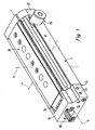
- eine bevorzugte erste Bauform des Linearantriebes in einer perspektivischen Rückansicht bei eingefahrener Schlittenendposition,
- Fig. 2
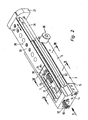
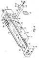
- den Linearantrieb aus Fig. 1 in einer entsprechenden Darstellung bei ausgefahrener Schlittenendposition,
- Fig. 3
- den in Fig. 1 gezeigten Zustand des Linearantriebes in einer perspektivischen Vorderansicht,
- Fig. 4
- den in Fig. 2 gezeigten Zustand des Linearantriebes in einer perspektivischen Vorderansicht, wobei der Einsatz eines auswechselbaren ersten Gegenanschlages angedeutet ist,
- Fig. 5
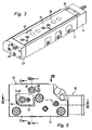
- eine Rückansicht des Linearantriebes mit Blickrichtung gemäß Pfeil V aus Fig. 2,
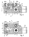
- Fig. 6
- einen Querschnitt durch den Linearantrieb gemäß Schnittlinie VI-VI aus Fig. 2,
- Fig. 7
- einen Querschnitt durch den Linearantrieb gemäß Schnittlinie VII-VII aus Fig. 2,
- Fig. 8
- den Linearantrieb bei eingefahrener Schlittenendposition gemäß Schnittlinie VIII-VIII aus Fig. 5,
- Fig. 9
- einen Längsschnitt des Linearantriebes gemäß Schnittlinie VIII-VIII aus Fig. 5, wobei der Schlitten die ausgefahrene Schlittenendposition gemäß Fig. 2 und 4 einnimmt,
- Fig. 10
- einen Längsschnitt bei dem in Fig. 8 gezeigten Betriebszustand und gemäß Schnittlinie X-X aus Fig. 5,
- Fig. 11
- einen Längsschnitt bei dem in Fig. 9 gezeigten Betriebszustand und wiederum gemäß Schnittlinie X-X,
- Fig. 12
- einen weiteren Längsschnitt durch den Linearantrieb bei die eingefahrene Schlittenposition einnehmendem Schlitten gemäß Schnittlinie XII-XII aus Fig. 5,
- Fig. 13
- einen entsprechend der Fig. 12 gelegten Schnitt durch den Linearantrieb bei die ausgefahrene Schlittenposition einnehmendem Schlitten und
- Fig. 14
- eine teilweise aufgebrochene Draufsicht des Linearantriebes mit Blickrichtung gemäß Pfeil XIV aus Fig. 5 in der ausgefahrenen Schlittenendposition.
- Fig. 1
- a preferred first design of the linear drive in a rear perspective view when retracted Schlittenendposition,
- Fig. 2
- 1 in a corresponding representation with extended Schlittenendposition,
- Fig. 3
- the state of the linear drive shown in Fig. 1 in a perspective front view,
- Fig. 4
- 2 shows the state of the linear drive shown in FIG. 2 in a perspective front view, the use of an exchangeable first counterstop being indicated,
- Fig. 5
- a rear view of the linear drive with a viewing direction according to arrow V of FIG. 2,
- Fig. 6
- a cross section through the linear drive according to section line VI-VI of Fig. 2,
- Fig. 7
- a cross section through the linear drive according to section line VII-VII of Fig. 2,
- Fig. 8
- the linear drive with retracted carriage end position according to section line VIII-VIII of Fig. 5,
- Fig. 9
- a longitudinal section of the linear drive according to section line VIII-VIII of FIG. 5, wherein the Carriage occupies the extended Schlittenendposition of FIG. 2 and 4,
- Fig. 10
- 8 shows a longitudinal section in the operating state shown in FIG. 8 and according to section line XX from FIG. 5, FIG.
- Fig. 11
- a longitudinal section in the operating state shown in Fig. 9 and again according to section line XX,
- Fig. 12
- a further longitudinal section through the linear drive in the retracted carriage position engaging carriage according to section line XII-XII of Fig. 5,
- Fig. 13
- a laid in accordance with FIG. 12 section through the linear drive in the extended slide position engaging carriage and
- Fig. 14
- a partially broken plan view of the linear drive with a view according to arrow XIV of Fig. 5 in the extended Schlittenendposition.
Der in der Zeichnung abgebildete Linearantrieb ist zur Betätigung mit Fluidkraft ausgelegt, könnte allerdings auch elektrisch aktivierbar sein.The linear drive shown in the drawing is designed for actuation with fluid power, but could also be electrically activated.
Der Linearantrieb besitzt ein Längsgestalt aufweisendes Antriebsgehäuse 2, mit einer Längsachse 3, einer dazu rechtwinkeligen Querachse 4 und einer zu den beiden vorgenannten Achsen wiederum rechtwinkeligen Hochachse 5. Die genannten drei Achsen spannen also ein kartesisches System auf.The linear drive has a
Das Antriebsgehäuse 2 ist im Querschnitt bevorzugt im Wesentlichen U-förmig profiliert (siehe insbesondere Fig. 6 und 7), wobei die beiden den U-Schenkeln entsprechenden Gehäuseabschnitte zwei parallel zueinander in Richtung der Längsachse 3 verlaufende erste und zweite Seitenwände 6, 7 definieren. Der dem U-Verbindungssteg entsprechende Gehäuseabschnitt bildet eine Bodenwand 8, die gemeinsam mit den beiden Seitenwänden 6, 7 eine kanalartige Gehäuseausnehmung 12 begrenzen, die an der der Bodenwand 8 entgegengesetzten Längsseite offen ist.The
An der rückwärtigen Stirnseite 13 ist die kanalartige Gehäuseausnehmung 12 durch eine an die Stirnfläche des Antriebsgehäuses 2 angesetzte stirnseitige Abschlusswand 14 begrenzt. An der entgegengesetzten vorderen Stirnseite 15 ist die Gehäuseausnehmung 12 hingegen offen.At the
Die erste Seitenwand 6 hat in Richtung der Querachse 4 eine größere Dicke als die verhältnismäßig schmale zweite Seitenwand 7. Dies rührt von einem in ihrem Innern ausgebildeten, längsverlaufenden und ringsum geschlossenen Hohlraum her, der als Antriebsraum 16 bezeichnet sei, da sich in seinem Innern zu einer Linearbewegung in Richtung der Längsachse 3 antreibbare Antriebsmittel 17 befinden.The
Die Antriebsmittel 17 bestehen beim Ausführungsbeispiel aus einem im Antriebsraum 16 verschiebbar angeordneten Kolben, der den Antriebsraum 16 unter Abdichtung in eine vordere und eine rückwärtige Arbeitskammer 18, 19 unterteilt. In jede Arbeitskammer 18, 19 mündet ein gesonderter Fluidkanal 22a, 22b, durch den hindurch ein fluidisches Druckmedium eingespeist oder abgeführt werden kann, um den Kolben 17 so gesteuert zu beaufschlagen, dass er sich in einer gewünschten Weise verlagert. Die Fluidversorgung geschieht über nicht näher dargestellte Fluidschläuche, die an mit den Fluidkanälen 22a, 22b kommunizierenden Anschlussöffnungen 23 anschließbar sind, welche sich zweckmäßigerweise an der Außenfläche der stirnseitigen Abschlusswand 14 befinden.The drive means 17 are in the embodiment of a displaceably arranged in the
Eine als Kolbenstange ausgebildete Koppelstange 24 ist einerseits an dem Kolben 17 befestigt und ragt andererseits im Bereich der vorderen Stirnseite 15 aus dem Antriebsgehäuse 2 heraus. Dabei durchsetzt sie unter Abdichtung einen von der vorderen Stirnseite 15 her in den Antriebsraum 16 eingesetzten stopfenartigen Abschlussdeckel 25, der mittels eines das Antriebsgehäuse 2 durchsetzenden Querstiftes 26 axial fixiert ist. Den rückwärtigen dichten Abschluss des Antriebsraumes 16 bewirkt die stirnseitige Abschlusswand 14, die die Mündung des Antriebsraumes 16 überdeckt.A
Der aus dem Antriebsgehäuse 2 herausragende Endabschnitt der Koppelstange 24 greift in zug- und druckfester Weise an einem Verbindungsjoch 27 an, das Bestandteil eines außen am Antriebsgehäuse 2 linear in Richtung der Längsachse 3 verstellbar geführten Schlittens 28 ist. Somit sind die Antriebsmittel 17 mit dem Schlitten 28 antriebsmäßig gekoppelt, und der Schlitten 18 führt bei entsprechender Betätigung der Antriebsmittel 17 eine gleichgerichtete lineare Hubbewegung 32 aus.The protruding from the
Wie insbesondere aus Fig. 6 und 7 ersichtlich ist, nimmt der Antriebsraum 16 innerhalb des Antriebsgehäuses 2 eine bezogen auf die Querachse 4 außermittige Position ein. Das Zentrum des Antriebsraumes 16 ist also in Richtung der Querachse 4 gegenüber dem Querschnittszentrum des Antriebsgehäuses 2 zum Gehäuserand hin versetzt.As can be seen in particular from FIGS. 6 and 7, the
Der Schlitten 28 hingegen ist der kanalartigen Gehäuseausnehmung 12 zugeordnet, wobei er ein sich in Richtung der Längsachse 3 an das Verbindungsjoch 27 anschließendes plattenartiges Schlittenhauptteil 33 aufweist, an dessen dem Verbindungsjoch 27 entgegengesetzter Rückseite noch eine bevorzugt plattenartige Tragwand 34 angesetzt ist.The
Das Schlittenhauptteil 33 ist so ausgerichtet, dass seine Erstreckungsebene 35 rechtwinkelig zur Hochachse 5 verläuft.The carriage
Die Länge des Schlittens 28 entspricht im Wesentlichen derjenigen des Antriebsgehäuses 2, wobei sich der Schlitten 28 vor allem mit seinem Schlittenhauptteil 33 im Bereich der offenen Längsseite der kanalartigen Gehäuseausnehmung 12 entlang dieser erstreckt. Somit bildet er praktisch eine Abdeckung für die offene Längsseite der Gehäuseausnehmung 12, wobei die abgedeckte Länge variabel und von der momentanen Position des Schlittens 28 abhängig ist. Ist die Koppelstange 24 weitestmöglich in den Antriebsraum 16 eingefahren, ergibt sich die aus Fig. 1 und 3 ersichtliche eingefahrene Schlittenposition, in der der Schlitten 28 die kanalartige Gehäuseausnehmung 12 über praktisch ihre gesamte Länge hinweg abdeckt. Ist die Koppelstange 24 hingegen weiter aus dem Antriebsgehäuse 2 ausgefahren, ragt auch der Schlitten 28 weiter über die vordere Stirnseite 15 des Antriebsgehäuses 2 hinaus, sodass nurmehr der der vorderen Stirnseite 15 zugeordnete Längenabschnitt der Gehäuseausnehmung 12 vom Schlitten 28 abgedeckt wird, während die Gehäuseausnehmung 12 im Übrigen offen liegt (Fig. 2 und 4).The length of the
Der Schlitten 28 ist in Richtung der Hochachse 5 so versenkt in der kanalartigen Gehäuseausnehmung 12 angeordnet, dass er an seinen beiden Längsseiten von den beiden Seitenwänden 6, 7 flankiert wird. Dies ist aus Fig. 7 gut ersichtlich. Als Resultat ergibt sich, dass der Schlitten 28 nicht oder nur geringfügig in Richtung der Hochachse 5 über das Antriebsgehäuse 2 vorsteht, was eine verhältnismäßig niedrige Bauhöhe zulässt.The
Zur Führung und Abstützung des Schlittens 28 bezüglich des Antriebsgehäuses 2 ist eine Führungseinrichtung 36 vorgesehen, die über zwei parallel und mit Abstand zueinander angeordnete Führungseinheiten 37a, 37b verfügt, die in Richtung der Querachse 4 zwischen dem Schlitten 28 und dem Antriebsgehäuse 2 platziert sind. Genauer gesagt wird der Schlitten 28 an seinen einander entgegengesetzten Längsseiten außen von den beiden Führungseinheiten 37a, 37b flankiert, wobei jede Führungseinheit 37a, 37b wiederum von einem Endabschnitt der am Schlitten 28 vorbeigreifenden Seitenwände 6, 7 flankiert ist. Gemäß Fig. 6 und 7 erstrecken sich die beiden Führungseinheiten 37a, 37b gemeinsam in einer zur Hochachse 5 rechtwinkeligen Führungsebene 38, wobei diese Führungsebene 38 beim Ausführungsbeispiel mit der Erstreckungsebene 35 des Schlittenhauptteils 33 zusammenfällt.To guide and support the
Jede Führungseinheit 37a, 37b besitzt eine an der der jeweils anderen Seitenwand zugewandten Innenseite der zugeordneten ersten bzw. zweiten Seitenwand 6, 7 angeordnete gehäuseseitige Führungsbahn 42. Diese gehäuseseitigen Führungsbahnen 42 erstrecken sich zweckmäßigerweise über die gesamte Länge des Antriebsgehäuses 2. Jeder gehäuseseitigen Führungsbahn 42 liegt in Richtung der Querachse 4 eine schlittenseitige Führungsbahn 43 gegenüber, die sich entlang des Schlittenhauptteils 33 erstreckt. Zwischen jedem Paar einander zugeordneter gehäuseseitiger und schlittenseitiger Führungsbahnen 42, 43 befindet sich eine Lagerelementanordnung 44, die sich insbesondere aus einer Gruppe von in einem Käfig zusammengefassten Wälzlagerelementen zusammensetzt. Führt der Schlitten 28 eine Hubbewegung 32 aus, läuft die Lagerelementanordnung 44 an den mit ihr kooperierenden Führungsbahnen 42, 43 ab, sodass sich eine präzise Linearführung für den Schlitten 28 einstellt.Each
Die Führungsbahnen 42, 43 sind bevorzugt an leistenförmigen Führungselementen ausgebildet, die an dem Antriebsgehäuse 2 bzw. dem Schlitten 28 fest angebracht sind.The
Über die Führungseinrichtung 36 werden am Schlitten 28 angreifende Kräfte in das Antriebsgehäuse 2 eingeleitet. Diese Kräfte können von einer beliebigen Masse herrühren, die an dem Schlitten 28 zum Zwecke einer Verlagerung befestigt wird. Bei dieser Masse kann es sich beispielsweise um eine Komponente einer Maschine oder um einen weiteren Linearantrieb handeln. An dem Schlitten 28 angeordnete Befestigungsmittel 45, beispielsweise in Gestalt von Gewindebohrungen, ermöglichen die lösbare Befestigung der jeweiligen Last. Diese Befestigungsmittel 45 sind zweckmäßigerweise sowohl an dem Schlittenhauptteil 33 als auch an dem Verbindungsjoch 27 vorgesehen.Via the guide device 36 forces acting on the
Die Führungseinheiten 37a, 37b sind vorzugsweise so installiert, dass die sich ergebende Führungsebene 38 in Richtung der Hochachse 5 versetzt zum Antriebsraum 16 angeordnet ist. Die Größe des Versatzes ist insbesondere so gewählt, dass das Schlittenhauptteil 33 in Richtung der Hochachse 5 höher liegt als der obere Scheitelbereich 46 des Antriebsraumes 16. Auf diese Weise ergibt sich die beim Ausführungsbeispiel realisierte vorteilhafte Möglichkeit, die gehäusefeste Führungsbahn 42 der der ersten Seitenwand 6 zugeordneten ersten Führungseinheit 37a in Richtung der Hochachse 5 über dem Antriebsraum 16 zu platzieren, sodass der Antriebsraum 16 in Richtung der Querachse 4 wenigstens ein Stück weit von dem die schlittenseitige Führungsbahn 43 der ersten Führungseinheit 37a tragenden längsseitigen Randabschnitt 47 des Schlittens 28 übergriffen wird.The
Es kann insbesondere vorgesehen sein, dass sich die gehäuseseitige Führungsbahn 42 der ersten Führungseinheit 37a im Wesentlichen in der Zone über dem oberen Scheitelbereich 46 des Antriebsraumes 16 befindet.It can be provided, in particular, that the housing-
Der Schlitten 28 ist also so angeordnet, dass er den Antriebsraum 16 ein Stück weit in Querrichtung des Antriebsgehäuses 2 überlappt, andererseits aber gemeinsam mit den beiden Seitenwänden 6, 7 und der Bodenwand 8 einen Hohlraum begrenzt, der in der noch zu beschreibenden Weise sehr gut für Hubbegrenzungsmaßnahmen nutzbar ist.The
Da die beiden Führungseinheiten 37a, 37b in Richtung der Querachse 4 einen großen Abstand zueinander aufweisen, ergibt sich eine gute Abstützung des Schlittens 28 gegen an ihm angreifende Kippmomente. -Since the two
Zweckmäßigerweise überragt der Schlitten 28 den Antriebsraum 16 nur ein Stück weit, sodass längsseits neben dem zugeordneten Randabschnitt 47 des Schlittens 28 ein unabgedeckter Randabschnitt 48 der ersten Seitenwand 6 des Antriebsgehäuses 2 verbleibt, der zur Integration einer oder mehrerer, in Richtung der Längsachse 3 verlaufender Verankerungsnuten 52 nutzbar ist. Diese Verankerungsnuten 52 ermöglichen insbesondere die Verankerung von Sensoren, mit denen sich eine berührungslose Positionserfassung der im Antriebsraum 16 angeordneten Antriebsmittel 17 bewerkstelligen lässt. Auf diese Weise können letztlich die interessierenden Hubpositionen des Schlittens 28 detektiert werden.Conveniently, the
Indem der vom Schlitten 28 unabgedeckte Randabschnitt 48 der zweiten Seitenwand 7 eine abgerundete Kontur besitzt, können problemlos mehrere und insbesondere zwei Verankerungsnuten ohne gegenseitige Behinderung längsseits nebeneinanderliegend realisiert werden.By having the
Der Linearantrieb ist mit Hubbegrenzungsmitteln 53 ausgestattet, die eine variable Hubbegrenzung des Schlittens 28 bei beiden Hubrichtungen ermöglichen. Somit besteht die Möglichkeit, unabhängig von dem durch die Antriebsmittel 17 realisierbaren Hub die im ausgefahrenen Zustand gewünschte ausgefahrene Schlittenendposition und die im eingefahrenen Zustand gewünschte eingefahrene Schlittenendposition vorzugeben. Die Hubbegrenzungsmittel 53 wirken mittelbar oder unmittelbar zwischen dem Antriebsgehäuse 2 und dem Schlitten 28.The linear drive is equipped with
Zur Vorgabe der ausgefahrenen Schlittenendposition sind ein am Schlitten 28 angeordneter erster Anschlag 54 und ein in dessen Bewegungsbahn ragender, gehäusefester erster Gegenanschlag 55 vorgesehen. Beide Anschläge befinden sich innerhalb der kanalartigen Gehäuseausnehmung 12 in dem Höhenabschnitt 56, der bei eingefahrenem Schlitten 28 in Höhenrichtung zwischen dem Schlitten 28 und der Bodenwand 8 definiert ist.To specify the extended Schlittenendposition a arranged on the
Der erste Anschlag 54 ist an der der stirnseitigen Abschlusswand 14 zugewandten rückwärtigen Stirnseite des Schlittens 28 angeordnet, wobei er zweckmäßigerweise an dem in den Höhenabschnitt 56 ragenden Abschnitt der Tragwand 34 angeordnet ist. Der erste Anschlag 54 hat eine in Ausfahrrichtung, also zum Verbindungsjoch 27 hin, orientierte erste Anschlagfläche 57, der eine am ersten Gegenanschlag 55 angeordnete erste Gegenanschlagfläche 58 zugewandt ist, wobei sich der erste Gegenanschlag 55 in einem Bereich der kanalartigen Gehäuseausnehmung 12 befindet, der von dem Schlittenhauptteil 33 übergriffen wird. Der erste Gegenanschlag 55 wird somit durch den Schlitten 28 zur Umgebung hin abgeschirmt.The
Beim Ausführungsbeispiel ist der erste Anschlag 54 als Anschlagschraube 62 ausgebildet, die die Tragwand 34 durchsetzt, wobei ein die erste Anschlagfläche 57 aufweisender Anschlagkopf unter dem Schlitten 28 liegt, während ein mit einem Gewinde versehener Einstellschaft rückseitig in Richtung zur stirnseitigen Abschlusswand 14 von der Tragwand 34 absteht. Am freien Ende des Einstellschaftes der Anschlagschraube 62 befindet sich eine den Angriff eines Schraubwerkzeuges ermöglichende Betätigungspartie 63, wobei die Möglichkeit besteht, durch Verdrehen der Anschlagschraube 62 die Axialposition der ersten Anschlagfläche 57 mit Bezug zum Schlitten 28 axial, insbesondere stufenlos, variabel zu justieren. Geeignete Kontermittel 64 erlauben ein Sichern der getroffenen Einstellung.In the embodiment, the
Zur Installation des ersten Gegenanschlages 55 ist die in Richtung der Querachse 4 weiter vom Antriebsraum 16 entfernte zweite Seitenwand 7 mit mehreren Wanddurchbrechungen 65 versehen, die jeweils die kanalartige Gehäuseausnehmung 12 mit der Umgebung des Antriebsgehäuses 2 verbinden, wobei der erste Gegenanschlag 55 von außen her so in eine der Wanddurchbrechungen 65 eingesetzt ist, dass er seitlich in die Gehäuseausnehmung 12 und dort in die Bewegungsbahn des ersten Anschlages 54 hineinragt.For installation of the
Die Wanddurchbrechungen 65 sind in der Hubrichtung des Schlittens 28 mit Abstand zueinander angeordnet. Somit kann durch wahlweise Bestückung einer dieser Wanddurchbrechungen 65 der mögliche Ausfahrhub und mithin die vorgegebene ausgefahrene Schlittenendposition mehrstufig grob vorgegeben werden. Beim Ausführungsbeispiel sind insgesamt drei Wanddurchbrechungen 65 vorgesehen, wobei der erste Gegenanschlag 55 in der mittleren Wanddurchbrechung 65 installiert ist. Er könnte aber auch beispielsweise, wie dies in Fig. 4 angedeutet ist, in eine der beiden anderen Wanddurchbrechungen 65 eingesetzt werden, um zu erreichen, dass der Schlitten in der ausgefahrenen Schlittenendposition mehr oder weniger weit aus dem Antriebsgehäuse 2 ausgefahren ist.The
Man hat also die Möglichkeit, durch selektive Bestückung der Wanddurchbrechungen 65 mit einem ersten Gegenanschlag 55 eine Grobeinstellung des Ausfahrhubes vorzunehmen, um dann unter Justierung des ersten Anschlages 54 eine abschließende Feineinstellung vorzunehmen.So you have the opportunity by selective placement of the
Die Anzahl der Wanddurchbrechungen 65 und auch deren Abstand untereinander wird sich in der Regel an der Baulänge des Antriebsgehäuses 2 und am maximal möglichen Schlittenhub orientieren. Ist der maximal mögliche Schlittenhub beispielsweise sehr gering, kann auch bereits eine einzige Wanddurchbrechung 65 zur Installation eines ersten Gegenanschlages 55 ausreichen, sodass dort dann die weitere Einstellung ausschließlich über das Justieren des ersten Anschlages 54 bewerkstelligt wird.The number of
In der Einsetzrichtung 66 betrachtet ist die Außenkontur des ersten Gegenanschlages 55 so an die Innenkontur der betreffenden Wanddurchbrechung 65 angepasst, dass das Einsetzen ein Steckvorgang ist, im Rahmen dessen sich eine formschlüssige Verbindung zwischen dem ersten Gegenanschlag 55 und dem Antriebsgehäuse 2 einstellt, die eine Abstützung des ersten Gegenanschlages 55 in der Hubrichtung des Schlittens 28, zumindest in dessen Ausfahrrichtung, bewirkt.Viewed in the
Zweckmäßigerweise verfügt der erste Gegenanschlag 55 über eine Haltepartie 67 und eine diesbezüglich im Querschnitt kleinere Anschlagpartie 68, wobei letztere die erste Gegenanschlagfläche 58 trägt und gegenüber der Haltepartie 67 in der Einsetzrichtung 66 vorsteht. Die Wanddurchbrechung 65 ist in der Einsetzrichtung 66 abgestuft und erweitert sich zur Außenfläche 72 hin zu einem Befestigungsabschnitt 73, der partiell durch eine nach außen weisende, von der Bodenwand 8 definierte Befestigungsfläche 74 begrenzt ist. Im eingesetzten Zustand liegt die Haltepartie 67 an der Befestigungsfläche 74 an, während die Anschlagpartie 68 an der Befestigungsfläche 74 vorbei in die Gehäuseausnehmung 12 ragt. Durch eine lösbare Schraubverbindung zwischen der Haltepartie 67 und dem die Befestigungsfläche 74 aufweisenden Gehäuseabschnitt lässt sich der erste Gegenanschlag 55 sicher fixieren. Exemplarisch ist in diesem Zusammenhang eine Befestigungsschraube 75 gezeigt, die die Haltepartie 67 unter Abstützung daran durchsetzt und in eine zur Befestigungsfläche 74 offene Gewindebohrung 76 des Antriebsgehäuses 2 einschraubbar ist.Expediently, the
Die momentan nicht für Anschlagzwecke benötigte Wanddurchbrechung 65 kann jeweils lösbar durch einen Deckel 77 verschlossen werden, der beispielsweise in der gleichen Weise wie der erste Gegenanschlag 55 befestigt wird, oder aber beispielsweise auch durch eine Rastverbindung. Durch das Verschließen mit einem Deckel wird einem Eindringen von Verunreinigungen vorgebeugt. Während der erste Gegenanschlag 55 insbesondere aus Metall besteht, können die verwendeten Deckel durchaus aus Kunststoffmaterial gefertigt sein. -The
Die Formgebung ist insbesondere so gewählt, dass sich im installierten Zustand des ersten Gegenanschlages 55 wie auch der Deckel 77 außen ein bündiger Abschluss mit der Außenfläche 72 des Antriebsgehäuses 2 einstellt.The shape is particularly chosen so that adjusts a flush termination with the
Um bei Bedarf die Hubbegrenzungsfunktion überprüfen zu können, ist beim Ausführungsbeispiel die Außenkontur des ersten Gegenanschlages 55 so ausgebildet, dass sie nicht vollumfänglich der Innenkontur der zugeordneten Wanddurchbrechung 65 entspricht, sodass zwischen den beiden Konturen ein durchgehender Freiraum verbleibt, der ein Sichtfenster 78 definiert, durch das hindurch am ersten Gegenanschlag 55 vorbei von außen her ein Einblick auf die in der Gehäuseausnehmung 12 platzierte Anschlagpartie 68 möglich ist.In order to be able to check the stroke limiting function when required, the outer contour of the
Um den gegenseitigen Aufprall zu minimieren, ist der Gegenanschlag 55 mit einem zum ersten Anschlag 54 ragenden gummielastischen Pufferelement 82 bestückt. Zusätzlich oder alternativ könnte insbesondere der erste Anschlag 54 nicht als reiner Festanschlag wie beim Ausführungsbeispiel ausgebildet sein, sondern kombiniert mit Stoßdämpfermitteln.In order to minimize the mutual impact, the counter-stop 55 is equipped with a rubber-
Um auch die eingefahrene Schlittenendposition variabel vorgeben zu können, enthalten die Hubbegrenzungsmittel 53 zusätzlich noch einen vom Antriebsgehäuse 2 getragenen zweiten Anschlag 83, der vorzugsweise an der stirnseitigen Abschlusswand 14 angeordnet ist und eine in Richtung der Längsachse 3 dem Schlitten 28 zugewandte zweite Anschlagfläche 85 besitzt. Letzterer liegt eine in Einfahrrichtung des Schlittens orientierte zweite Gegenanschlagfläche 86 gegenüber, die an einem am rückwärtigen Endbereich des Schlittens 28 angeordneten zweiten Gegenanschlag 84 vorgesehen ist. Letzterer ist beim Ausführungsbeispiel unmittelbar von der Stirnfläche der Tragwand 34 gebildet, während der zweite Anschlag 83 vergleichbar dem ersten Anschlag 54 als Anschlagschraube 87 ausgeführt ist, die durch die stirnseitige Abschlusswand 14 hindurchgeschraubt ist und sich relativ zu dieser axial justieren lässt. Die Justierung und Fixierung erfolgt in gleicher Weise wie bei der den ersten Anschlag 54 bildenden Anschlagschraube 62.In order to specify the retracted slide end position variably, the
Auch dem zweiten Anschlag 83 ist beim Ausführungsbeispiel ein Pufferelement 88 zur Aufprallreduzierung zugeordnet.Also, the
Für alle Anschlagmittel gilt, dass bei Bedarf Stoßdämpfmittel vorgesehen sein können, entweder gesondert oder in Kombination mit dem betreffenden Anschlag, um insbesondere eine fluidische Endlagendämpfung, beispielsweise unter Verwendung hydraulischer Stoßdämpfer, vornehmen zu können.Shock absorbing means may be provided for all stop means, if required, either separately or in combination with the relevant stop, in order in particular to be able to effect a fluidic end position damping, for example by using hydraulic shock absorbers.
Der zweite Anschlag 83 ist zur Veränderung der eingefahrenen Schlittenendposition ohne weiteres von der Rückseite des Antriebsgehäuses 2 her zugänglich, da seine den Angriff eines Einstellwerkzeuges ermöglichende Betätigungspartie 91 auf der dem Schlitten 28 entgegengesetzten Außenseite der stirnseitigen Abschlusswand 14 liegt.The
Um eine vergleichbare Justierung auch des ersten Anschlages 54 vornehmen zu können, ist die Abschlusswand 14, in Hubrichtung des Schlittens 28 mit dem ersten Anschlag 54 fluchtend, mit einer fensterartigen Durchbrechung 92 versehen. Durch diese Durchbrechung 92 hindurch kann unabhängig von der Hubposition des Schlittens 28 eine Betätigung des ersten Anschlages 54 zu Justierzwecken erfolgen.In order to make a comparable adjustment of the
Es ergibt sich ferner der Vorteil, dass der erste Anschlag 62 mit seinem rückseitig über den Schlitten 28 vorstehenden Längenabschnitt in die fensterartige Durchbrechung 92 eintauchen oder gar durch diese Durchbrechung 92 hindurchragen kann, wenn der rückwärtige Endbereich des Schlittens 28 in der eingefahrenen Schlittenendposition in unmittelbarer Nähe zu der stirnseitigen Abschlusswand 14 zu liegen kommt. Dies ermöglicht eine beträchtliche Einsparung an Baulänge für das Antriebsgehäuse 2.It also results in the advantage that the
Beim Ausführungsbeispiel kommt der weitere Vorteil hinzu, dass der den ersten Anschlag 54 tragende Endbereich des Schlittens 28 - vorliegend gebildet von der Tragwand 34 - als Ausschiebekopf 93 fungiert, der beim Einfahrhub des Schlittens eventuell in der Gehäuseausnehmung 12 vorhandene Verunreinigungen bzw. Fremdkörper durch die fensterartige Durchbrechung 92 hindurch zur Umgebung hin ausstößt.In the embodiment, the further advantage that the
Damit die Verunreinigungen nicht etwa durch einen störenden Absatz im Übergangsbereich zu der Abschlusswand 14 zurückgehalten werden, ist die Innenkontur der fensterartigen Durchbrechung 92 zweckmäßigerweise so ausgebildet, dass sie mit den Innenflächen der die Gehäuseausnehmung 12 definierenden Seiten- und Bodenwände 6, 7, 8, zumindest im Bereich der Bodenwand 8, wenigstens fluchtet, vorzugsweise aber sogar wenigstens minimal quer zur Längsachse 3 zurückspringt. Der zurückspringende Bereich ist in Fig. 11 durch die Bezugsziffer 94 kenntlich gemacht.So that the contaminants are not retained by a disruptive heel in the transition region to the
Eine Berührung zwischen dem Ausschiebekopf 93 und dem Antriebsgehäuse 2 ist zur Gewährleistung der Ausschubfunktion nicht erforderlich, auch kann auf eine elastische Dichtung in der Regel verzichtet werden. Indem die Tragwand 34 eine der Innenkontur der Gehäuseausnehmung 12 im Wesentlichen entsprechende Außenkontur aufweist, kann ein sehr geringes Spaltmaß eingehalten werden, sodass auch ohne Berührung die Ausstoßfunktion gewährleistet ist. Wie die Zeichnung zeigt, ragt der Ausschiebekopf 93 zumindest annähernd bis zu der der offenen Längsseite der Gehäuseausnehmung 12 gegenüberliegenden Bodenwand 8 der kanalartigen Gehäuseausnehmung 12.A contact between the
Zweckmäßigerweise ist der Linearantrieb noch mit einer Klemmeinheit 95 ausgestattet, mit der sich die Koppelstange 24 während einer gewünschten Zeitspanne axial unbeweglich bezüge lich des Antriebsgehäuses 2 festsetzen lässt.Conveniently, the linear drive is still equipped with a
Die Klemmeinheit 95 ist patronenartig ausgebildet und in dem dem Abschlussdeckel 25 zum Verbindungsjoch 27 axial vorgelagerten Bereich von der Seite her in eine Ausnehmung 96 des Antriebsgehäuses 2 eingesetzt, wobei sie von der Koppelstange 24 durchsetzt wird. -The clamping
Die Klemmeinheit 95 ist insbesondere für fluidische Betätigung ausgelegt. Sie enthält zweckmäßigerweise zwei um eine rechtwinkelig zur Längsachse der Koppelstange 24 verlaufende Schwenkachse 98 verschwenkbare Klemmbacken 97, die beide von der Koppelstange 24 durchsetzt werden und die durch eine sich zwischen ihnen abstützende Federeinrichtung 99 normalerweise so auseinandergespreizt werden, dass sie klemmend auf den Außenumfang der Koppelstange 24 einwirken. Um die Blockierung aufzuheben, kann über einen Fluidanschluss 100 ein Druckmedium eingespeist werden, das einen Betätigungskolben 101 gegen die Klemmbacken 97 verschiebt, sodass diese entgegen der Federkraft in eine Lösestellung verschwenkt werden, in der die Koppelstange 24 für die Axialbewegung freigegeben ist.The clamping
Indem die Klemmeinheit 95 exakt in die zugeordnete Gehäuseausnehmung 12 eingepasst ist, kann eine in Hubrichtung des Schlittens 28 spielfreie Befestigung gewährleistet werden, was ein spielfreies Festsetzen der Kolbenstange und somit auch des mit dieser verbundenen Schlittens 28 gewährleistet.By the clamping
Claims (16)
- Linear drive with a drive housing (2) wherein drive means (17) capable of being driven to perform a linear movement and coupled for drive to a slide (28) guided for linear movement on the outside of the housing (2)are located, and with stroke limiting means (53) acting between the drive housing (2) and the slide (28) and comprising a first stop (54) located on the slide (28) and a first mating stop (55) located on the housing, which projects into the path of the first stop (54) and is overlapped by the slide (28), wherein the slide (28) is so arranged that, depending on position, it covers a shorter or longer section of the open side of a channel-like housing recess (12) of the drive housing (2) bounded by two opposite side walls (6, 7), and wherein the first stop (54) is located within the housing recess (12), characterised in that at least one of the side walls (7) has a wall aperture (65) into which the first mating stop (55) acting together with the first stop (54) can be installed from the outside to project laterally into the housing recess (12).
- Linear drive according to claim 1, characterised in that the drive housing (2) has a U-shaped contour to form the channel-like housing recess (12).
- Linear drive according to claim 1 or 2, characterised in that the slide (28) has a supporting wall (34) projecting into the channel-like housing recess (12) and supporting the first stop (54) in an end area.
- Linear drive according to claim 3, characterised in that the external contour of the supporting wall (34) essentially matches the internal contour of the channel-like housing recess (12).
- Linear drive according to claim 3 or 4, characterised in that the first stop (54) is mounted on the supporting wall (34) for axial, in particular continuous, adjustment.
- Linear drive according to any of claims 3 to 5, characterised in that the channel-like housing recess (12), in extension of the slide (28), is bounded by an end wall (14) located opposite the supporting wall (34), which has a window-like aperture (92) aligned with the first stop (54) in the direction of the stroke of the slide (28).
- Linear drive according to any of claims 1 to 6, characterised in that a plurality of wall apertures (65) optionally fitted with the first mating stop (55) is provided in one and the same side wall (7) at a distance from one another in the direction of the stroke of the slide (28).
- Linear drive according to claim 7, characterised by at least one cover (77) for releasably sealing the wall aperture(s) (65) not fitted with a first mating stop (55).
- Linear drive according to any of claims 1 to 8, characterised in that the first mating stop (55) can be positively installed into the wall aperture (65), so that it is supported against the drive housing (2) in the direction of the stroke of the slide (28).
- Linear drive according to any of claims 1 to 9, characterised in that the drive means (17) are connected to a coupling rod (24) projecting from the end face of the drive housing (2) and acting on the slide (28).
- Linear drive according to claim 10, characterised by a clamping unit (95) for the axially fixed location of the coupling rod (24) relative to the drive housing (2), which is installed into the drive housing (2) and through which the coupling rod (24) passes.
- Linear drive according to any of claims 1 to 11, characterised in that that the slide (28) is recessed into the channel-like housing recess (12), so that its two sides are flanked by the side walls (6, 7) of the housing recess (12).
- Linear drive according to any of claims 1 to 12, characterised in that the first mating stop (55) installed into a wall aperture (65) is externally flush with the outer surface (72) of the drive housing (2).
- Linear drive according to any of claims 1 to 13, characterised in that the external contour of the first mating stop (55) is so matched to the internal contour of the associated wall aperture (65) that a window (78) allowing a lateral view into the channel-like housing recess (12) is defined between the two contours.
- Linear drive according to any of claims 1 to 14, characterised in that a pair of co-operating second stops and mating stops (83, 84) is provided which, compared to the pair of first stops and mating stops (54, 55), becomes effective in the opposite direction of the stroke of the slide (28).
- Linear drive according to claim 15, characterised in that the second stop (84) is located in an end area of the slide (28) within the channel-like housing recess (12) and the second stop (83) is located in axial extension thereof at an end wall (14) of the drive housing (2) bounding the end of the housing recess (12).
Priority Applications (5)
| Application Number | Priority Date | Filing Date | Title |
|---|---|---|---|
| AT04400012T ATE327074T1 (en) | 2004-03-01 | 2004-03-01 | LINEAR DRIVE WITH SPECIAL DESIGN OF STOPS TO LIMIT THE STROKE OF THE SLIDE |
| DE502004000625T DE502004000625D1 (en) | 2004-03-01 | 2004-03-01 | Linear drive with special design of stops for stroke limitation of the carriage |
| EP04400012A EP1574283B1 (en) | 2004-03-01 | 2004-03-01 | Linear actuator with special configuration of abutments for limiting the stroke of the slide |
| US11/056,465 US7207262B2 (en) | 2004-03-01 | 2005-02-11 | Linear drive |
| CN200510051748.5A CN1663736B (en) | 2004-03-01 | 2005-03-01 | Linear actuator |
Applications Claiming Priority (1)
| Application Number | Priority Date | Filing Date | Title |
|---|---|---|---|
| EP04400012A EP1574283B1 (en) | 2004-03-01 | 2004-03-01 | Linear actuator with special configuration of abutments for limiting the stroke of the slide |
Publications (2)
| Publication Number | Publication Date |
|---|---|
| EP1574283A1 EP1574283A1 (en) | 2005-09-14 |
| EP1574283B1 true EP1574283B1 (en) | 2006-05-24 |
Family
ID=34814445
Family Applications (1)
| Application Number | Title | Priority Date | Filing Date |
|---|---|---|---|
| EP04400012A Expired - Lifetime EP1574283B1 (en) | 2004-03-01 | 2004-03-01 | Linear actuator with special configuration of abutments for limiting the stroke of the slide |
Country Status (5)
| Country | Link |
|---|---|
| US (1) | US7207262B2 (en) |
| EP (1) | EP1574283B1 (en) |
| CN (1) | CN1663736B (en) |
| AT (1) | ATE327074T1 (en) |
| DE (1) | DE502004000625D1 (en) |
Cited By (2)
| Publication number | Priority date | Publication date | Assignee | Title |
|---|---|---|---|---|
| DE102020210289B3 (en) | 2020-08-13 | 2021-11-18 | Festo Se & Co. Kg | Fluid operated linear drive |
| DE102020210344B3 (en) | 2020-08-14 | 2021-11-18 | Festo Se & Co. Kg | Fluid operated linear drive |
Families Citing this family (6)
| Publication number | Priority date | Publication date | Assignee | Title |
|---|---|---|---|---|
| JP4587105B2 (en) * | 2005-05-18 | 2010-11-24 | Smc株式会社 | Linear actuator and processing method thereof |
| WO2008093113A2 (en) * | 2007-02-02 | 2008-08-07 | G24 Innovations Limited | A method of manufacturing an electrode array for photovoltaic electrochemical cell arrays |
| TWI383276B (en) * | 2007-12-04 | 2013-01-21 | Smc Kk | Electric actuator |
| US9303742B2 (en) * | 2011-11-28 | 2016-04-05 | Pacific Bearing Company | Inverted spline rail system |
| USD748704S1 (en) * | 2014-05-28 | 2016-02-02 | Jenny Science Ag | Linear motor electic slide |
| JP1528331S (en) * | 2014-09-11 | 2015-07-13 |
Family Cites Families (7)
| Publication number | Priority date | Publication date | Assignee | Title |
|---|---|---|---|---|
| DE9416523U1 (en) * | 1994-10-14 | 1994-12-01 | Festo Kg | linear actuator |
| US5568982A (en) * | 1994-10-14 | 1996-10-29 | Festo Kg | Linear drive |
| GB2316132B (en) * | 1996-08-13 | 1999-02-17 | Smc Kk | Linear actuator |
| DE19649719C2 (en) * | 1996-11-30 | 1999-02-04 | Festo Ag & Co | linear actuator |
| DE29706098U1 (en) * | 1997-04-05 | 1997-05-28 | Festo Kg | Carriage drive device |
| DE10013195B4 (en) * | 2000-03-17 | 2008-05-21 | Festo Ag & Co. | Linear drive unit |
| DE502004000628D1 (en) * | 2004-03-01 | 2006-06-29 | Festo Ag & Co | Linear drive with a slide flanked by two guide units |
-
2004
- 2004-03-01 AT AT04400012T patent/ATE327074T1/en active
- 2004-03-01 DE DE502004000625T patent/DE502004000625D1/en not_active Expired - Lifetime
- 2004-03-01 EP EP04400012A patent/EP1574283B1/en not_active Expired - Lifetime
-
2005
- 2005-02-11 US US11/056,465 patent/US7207262B2/en active Active
- 2005-03-01 CN CN200510051748.5A patent/CN1663736B/en not_active Expired - Fee Related
Cited By (2)
| Publication number | Priority date | Publication date | Assignee | Title |
|---|---|---|---|---|
| DE102020210289B3 (en) | 2020-08-13 | 2021-11-18 | Festo Se & Co. Kg | Fluid operated linear drive |
| DE102020210344B3 (en) | 2020-08-14 | 2021-11-18 | Festo Se & Co. Kg | Fluid operated linear drive |
Also Published As
| Publication number | Publication date |
|---|---|
| ATE327074T1 (en) | 2006-06-15 |
| US20050193844A1 (en) | 2005-09-08 |
| CN1663736B (en) | 2010-05-26 |
| CN1663736A (en) | 2005-09-07 |
| US7207262B2 (en) | 2007-04-24 |
| DE502004000625D1 (en) | 2006-06-29 |
| EP1574283A1 (en) | 2005-09-14 |
Similar Documents
| Publication | Publication Date | Title |
|---|---|---|
| EP1616659B1 (en) | Linear actuator with a slide guided on two side guides | |
| EP3352955B1 (en) | Gripping or clamping device | |
| EP0868965A2 (en) | Carriage drive mechanisme | |
| EP2047116B1 (en) | Fluid-actuated linear unit, in particular linear drive | |
| DE4206319C2 (en) | Needle valve with piston drive | |
| EP0710774A2 (en) | Power cylinder | |
| EP0886036B1 (en) | Compressed air piston motor | |
| DE10013022A1 (en) | Parallel gripper; has casing with guiding recess for two adjustable base jaws, which are moved together or apart by wedge hook gearing that can be adjusted by piston guided in casing | |
| EP1574283B1 (en) | Linear actuator with special configuration of abutments for limiting the stroke of the slide | |
| DE102008013374B4 (en) | Hydropneumatic pressure translation device, working machine and machine tool | |
| EP3205892B1 (en) | Fluid actuated linear unit | |
| EP1245346B1 (en) | Fluid actuated parallel grippper with two actuating units | |
| DE4024716A1 (en) | PRESSURE CYLINDER WITH LENGTH SLIT CYLINDER PIPE | |
| EP1050685B1 (en) | Hydraulic linear slider | |
| DE102006018088B4 (en) | Guide mechanism for cylinder device | |
| WO2006106070A1 (en) | Damping device for linear drives | |
| EP1182359A1 (en) | Rodless linear drive and its housing | |
| DE102004011625B4 (en) | linear actuator | |
| EP1703144B1 (en) | Linear fluid actuator | |
| DE10108257B4 (en) | hydraulic cylinders | |
| DE102020204569A1 (en) | Linear motion unit | |
| DE202009004685U1 (en) | linear actuator | |
| DE10038892C2 (en) | Brake cylinder housing for a disc brake | |
| DE102020210344B3 (en) | Fluid operated linear drive | |
| DE102018110289A1 (en) | HYDRAULIC PISTON / CYLINDER UNIT WITH A PROTECTION DEVICE FOR A PISTON ROD AND WORKING VEHICLE THEREWITH |
Legal Events
| Date | Code | Title | Description |
|---|---|---|---|
| PUAI | Public reference made under article 153(3) epc to a published international application that has entered the european phase |
Free format text: ORIGINAL CODE: 0009012 |
|
| 17P | Request for examination filed |
Effective date: 20040903 |
|
| AK | Designated contracting states |
Kind code of ref document: A1 Designated state(s): AT BE BG CH CY CZ DE DK EE ES FI FR GB GR HU IE IT LI LU MC NL PL PT RO SE SI SK TR |
|
| AX | Request for extension of the european patent |
Extension state: AL LT LV MK |
|
| GRAP | Despatch of communication of intention to grant a patent |
Free format text: ORIGINAL CODE: EPIDOSNIGR1 |
|
| GRAC | Information related to communication of intention to grant a patent modified |
Free format text: ORIGINAL CODE: EPIDOSCIGR1 |
|
| GRAS | Grant fee paid |
Free format text: ORIGINAL CODE: EPIDOSNIGR3 |
|
| GRAA | (expected) grant |
Free format text: ORIGINAL CODE: 0009210 |
|
| AK | Designated contracting states |
Kind code of ref document: B1 Designated state(s): AT BE BG CH CY CZ DE DK EE ES FI FR GB GR HU IE IT LI LU MC NL PL PT RO SE SI SK TR |
|
| PG25 | Lapsed in a contracting state [announced via postgrant information from national office to epo] |
Ref country code: IE Free format text: LAPSE BECAUSE OF FAILURE TO SUBMIT A TRANSLATION OF THE DESCRIPTION OR TO PAY THE FEE WITHIN THE PRESCRIBED TIME-LIMIT Effective date: 20060524 Ref country code: CZ Free format text: LAPSE BECAUSE OF FAILURE TO SUBMIT A TRANSLATION OF THE DESCRIPTION OR TO PAY THE FEE WITHIN THE PRESCRIBED TIME-LIMIT Effective date: 20060524 Ref country code: IT Free format text: LAPSE BECAUSE OF FAILURE TO SUBMIT A TRANSLATION OF THE DESCRIPTION OR TO PAY THE FEE WITHIN THE PRESCRIBED TIME-LIMIT;WARNING: LAPSES OF ITALIAN PATENTS WITH EFFECTIVE DATE BEFORE 2007 MAY HAVE OCCURRED AT ANY TIME BEFORE 2007. THE CORRECT EFFECTIVE DATE MAY BE DIFFERENT FROM THE ONE RECORDED. Effective date: 20060524 Ref country code: SI Free format text: LAPSE BECAUSE OF FAILURE TO SUBMIT A TRANSLATION OF THE DESCRIPTION OR TO PAY THE FEE WITHIN THE PRESCRIBED TIME-LIMIT Effective date: 20060524 Ref country code: NL Free format text: LAPSE BECAUSE OF FAILURE TO SUBMIT A TRANSLATION OF THE DESCRIPTION OR TO PAY THE FEE WITHIN THE PRESCRIBED TIME-LIMIT Effective date: 20060524 Ref country code: PL Free format text: LAPSE BECAUSE OF FAILURE TO SUBMIT A TRANSLATION OF THE DESCRIPTION OR TO PAY THE FEE WITHIN THE PRESCRIBED TIME-LIMIT Effective date: 20060524 Ref country code: RO Free format text: LAPSE BECAUSE OF FAILURE TO SUBMIT A TRANSLATION OF THE DESCRIPTION OR TO PAY THE FEE WITHIN THE PRESCRIBED TIME-LIMIT Effective date: 20060524 Ref country code: SK Free format text: LAPSE BECAUSE OF FAILURE TO SUBMIT A TRANSLATION OF THE DESCRIPTION OR TO PAY THE FEE WITHIN THE PRESCRIBED TIME-LIMIT Effective date: 20060524 |
|
| REG | Reference to a national code |
Ref country code: GB Ref legal event code: FG4D Free format text: NOT ENGLISH |
|
| AKX | Designation fees paid |
Designated state(s): AT BE BG CH CY CZ DE DK EE ES FI FR GB GR HU IE IT LI LU MC NL PL PT RO SE SI SK TR |
|
| REG | Reference to a national code |
Ref country code: CH Ref legal event code: NV Representative=s name: TROESCH SCHEIDEGGER WERNER AG Ref country code: CH Ref legal event code: EP |
|
| GBT | Gb: translation of ep patent filed (gb section 77(6)(a)/1977) |
Effective date: 20060524 |
|
| REG | Reference to a national code |
Ref country code: IE Ref legal event code: FG4D Free format text: LANGUAGE OF EP DOCUMENT: GERMAN |
|
| REF | Corresponds to: |
Ref document number: 502004000625 Country of ref document: DE Date of ref document: 20060629 Kind code of ref document: P |
|
| PG25 | Lapsed in a contracting state [announced via postgrant information from national office to epo] |
Ref country code: DK Free format text: LAPSE BECAUSE OF FAILURE TO SUBMIT A TRANSLATION OF THE DESCRIPTION OR TO PAY THE FEE WITHIN THE PRESCRIBED TIME-LIMIT Effective date: 20060824 |
|
| PG25 | Lapsed in a contracting state [announced via postgrant information from national office to epo] |
Ref country code: ES Free format text: LAPSE BECAUSE OF FAILURE TO SUBMIT A TRANSLATION OF THE DESCRIPTION OR TO PAY THE FEE WITHIN THE PRESCRIBED TIME-LIMIT Effective date: 20060904 |
|
| REG | Reference to a national code |
Ref country code: SE Ref legal event code: TRGR |
|
| PG25 | Lapsed in a contracting state [announced via postgrant information from national office to epo] |
Ref country code: PT Free format text: LAPSE BECAUSE OF FAILURE TO SUBMIT A TRANSLATION OF THE DESCRIPTION OR TO PAY THE FEE WITHIN THE PRESCRIBED TIME-LIMIT Effective date: 20061024 |
|
| NLV1 | Nl: lapsed or annulled due to failure to fulfill the requirements of art. 29p and 29m of the patents act | ||
| REG | Reference to a national code |
Ref country code: IE Ref legal event code: FD4D |
|
| ET | Fr: translation filed | ||
| PLBE | No opposition filed within time limit |
Free format text: ORIGINAL CODE: 0009261 |
|
| STAA | Information on the status of an ep patent application or granted ep patent |
Free format text: STATUS: NO OPPOSITION FILED WITHIN TIME LIMIT |
|
| 26N | No opposition filed |
Effective date: 20070227 |
|
| BERE | Be: lapsed |
Owner name: FESTO A.G. & CO Effective date: 20070331 |
|
| PG25 | Lapsed in a contracting state [announced via postgrant information from national office to epo] |
Ref country code: BE Free format text: LAPSE BECAUSE OF NON-PAYMENT OF DUE FEES Effective date: 20070331 |
|
| PG25 | Lapsed in a contracting state [announced via postgrant information from national office to epo] |
Ref country code: MC Free format text: LAPSE BECAUSE OF NON-PAYMENT OF DUE FEES Effective date: 20070331 |
|
| PG25 | Lapsed in a contracting state [announced via postgrant information from national office to epo] |
Ref country code: GR Free format text: LAPSE BECAUSE OF FAILURE TO SUBMIT A TRANSLATION OF THE DESCRIPTION OR TO PAY THE FEE WITHIN THE PRESCRIBED TIME-LIMIT Effective date: 20060825 |
|
| PG25 | Lapsed in a contracting state [announced via postgrant information from national office to epo] |
Ref country code: BG Free format text: LAPSE BECAUSE OF FAILURE TO SUBMIT A TRANSLATION OF THE DESCRIPTION OR TO PAY THE FEE WITHIN THE PRESCRIBED TIME-LIMIT Effective date: 20060824 |
|
| PG25 | Lapsed in a contracting state [announced via postgrant information from national office to epo] |
Ref country code: EE Free format text: LAPSE BECAUSE OF FAILURE TO SUBMIT A TRANSLATION OF THE DESCRIPTION OR TO PAY THE FEE WITHIN THE PRESCRIBED TIME-LIMIT Effective date: 20060524 |
|
| PGFP | Annual fee paid to national office [announced via postgrant information from national office to epo] |
Ref country code: FI Payment date: 20090211 Year of fee payment: 6 |
|
| PG25 | Lapsed in a contracting state [announced via postgrant information from national office to epo] |
Ref country code: LU Free format text: LAPSE BECAUSE OF NON-PAYMENT OF DUE FEES Effective date: 20070301 Ref country code: CY Free format text: LAPSE BECAUSE OF FAILURE TO SUBMIT A TRANSLATION OF THE DESCRIPTION OR TO PAY THE FEE WITHIN THE PRESCRIBED TIME-LIMIT Effective date: 20060524 |
|
| PG25 | Lapsed in a contracting state [announced via postgrant information from national office to epo] |
Ref country code: TR Free format text: LAPSE BECAUSE OF FAILURE TO SUBMIT A TRANSLATION OF THE DESCRIPTION OR TO PAY THE FEE WITHIN THE PRESCRIBED TIME-LIMIT Effective date: 20060524 Ref country code: HU Free format text: LAPSE BECAUSE OF FAILURE TO SUBMIT A TRANSLATION OF THE DESCRIPTION OR TO PAY THE FEE WITHIN THE PRESCRIBED TIME-LIMIT Effective date: 20061125 |
|
| PG25 | Lapsed in a contracting state [announced via postgrant information from national office to epo] |
Ref country code: FI Free format text: LAPSE BECAUSE OF NON-PAYMENT OF DUE FEES Effective date: 20100301 |
|
| PGFP | Annual fee paid to national office [announced via postgrant information from national office to epo] |
Ref country code: SE Payment date: 20120319 Year of fee payment: 9 |
|
| PGFP | Annual fee paid to national office [announced via postgrant information from national office to epo] |
Ref country code: AT Payment date: 20130218 Year of fee payment: 10 |
|
| REG | Reference to a national code |
Ref country code: SE Ref legal event code: EUG |
|
| PG25 | Lapsed in a contracting state [announced via postgrant information from national office to epo] |
Ref country code: SE Free format text: LAPSE BECAUSE OF NON-PAYMENT OF DUE FEES Effective date: 20130302 |
|
| PGFP | Annual fee paid to national office [announced via postgrant information from national office to epo] |
Ref country code: FR Payment date: 20140319 Year of fee payment: 11 |
|
| REG | Reference to a national code |
Ref country code: AT Ref legal event code: MM01 Ref document number: 327074 Country of ref document: AT Kind code of ref document: T Effective date: 20140301 |
|
| PG25 | Lapsed in a contracting state [announced via postgrant information from national office to epo] |
Ref country code: AT Free format text: LAPSE BECAUSE OF NON-PAYMENT OF DUE FEES Effective date: 20140301 |
|
| PGFP | Annual fee paid to national office [announced via postgrant information from national office to epo] |
Ref country code: CH Payment date: 20150331 Year of fee payment: 12 |
|
| REG | Reference to a national code |
Ref country code: FR Ref legal event code: ST Effective date: 20151130 |
|
| PG25 | Lapsed in a contracting state [announced via postgrant information from national office to epo] |
Ref country code: FR Free format text: LAPSE BECAUSE OF NON-PAYMENT OF DUE FEES Effective date: 20150331 |
|
| PGFP | Annual fee paid to national office [announced via postgrant information from national office to epo] |
Ref country code: GB Payment date: 20160309 Year of fee payment: 13 |
|
| PGFP | Annual fee paid to national office [announced via postgrant information from national office to epo] |
Ref country code: IT Payment date: 20160318 Year of fee payment: 13 |
|
| REG | Reference to a national code |
Ref country code: CH Ref legal event code: PL |
|
| PG25 | Lapsed in a contracting state [announced via postgrant information from national office to epo] |
Ref country code: LI Free format text: LAPSE BECAUSE OF NON-PAYMENT OF DUE FEES Effective date: 20160331 Ref country code: CH Free format text: LAPSE BECAUSE OF NON-PAYMENT OF DUE FEES Effective date: 20160331 |
|
| GBPC | Gb: european patent ceased through non-payment of renewal fee |
Effective date: 20170301 |
|
| PG25 | Lapsed in a contracting state [announced via postgrant information from national office to epo] |
Ref country code: GB Free format text: LAPSE BECAUSE OF NON-PAYMENT OF DUE FEES Effective date: 20170301 Ref country code: IT Free format text: LAPSE BECAUSE OF NON-PAYMENT OF DUE FEES Effective date: 20170301 |
|
| REG | Reference to a national code |
Ref country code: DE Ref legal event code: R082 Ref document number: 502004000625 Country of ref document: DE Representative=s name: PATENTANWAELTE MAGENBAUER & KOLLEGEN PARTNERSC, DE Ref country code: DE Ref legal event code: R081 Ref document number: 502004000625 Country of ref document: DE Owner name: FESTO SE & CO. KG, DE Free format text: FORMER OWNER: FESTO AG & CO. KG, 73734 ESSLINGEN, DE Ref country code: DE Ref legal event code: R081 Ref document number: 502004000625 Country of ref document: DE Owner name: FESTO AG & CO. KG, DE Free format text: FORMER OWNER: FESTO AG & CO. KG, 73734 ESSLINGEN, DE |
|
| PGFP | Annual fee paid to national office [announced via postgrant information from national office to epo] |
Ref country code: DE Payment date: 20210208 Year of fee payment: 18 |
|
| REG | Reference to a national code |
Ref country code: DE Ref legal event code: R119 Ref document number: 502004000625 Country of ref document: DE |
|
| PG25 | Lapsed in a contracting state [announced via postgrant information from national office to epo] |
Ref country code: DE Free format text: LAPSE BECAUSE OF NON-PAYMENT OF DUE FEES Effective date: 20221001 |