Technical Field
The present invention relates to a composite material member composed of a
light metal of a light metal alloy (hereinafter, "main material") used in engine blocks for
automobiles, piston, parts for aircraft, and radiator plates for electronic devices, and to a
secondary material which is different from the main material, and specifically relates to a
technique in which strength and durability in a joined part between constituent materials
of a composite material member are improved and production cost is decreased.
Background Art
Recently, in order to respond to a demand for weight reduction in automobile
parts and aircraft parts, light metals such Al alloys are often used. However, when a
light metal is used, generally, it is necessary to combine the light metal with a secondary
material which can provide the required characteristics, so as to compensate for
problems in characteristics in the light metal, such as strength at elevated temperature,
wear resistance and coefficient of thermal expansion (see Japanese Laid-open Utility
Model No. 5-71474, specification (Page 1)).
In the combining, while there was an advantage in obtaining the characteristics,
there was a disadvantage of having a low joining strength due to combining different
kinds of materials, and there was therefore a problem in that the materials are easily
peeled when external force acted on the materials or the materials were exposed to
environments having large temperature variations. As efforts to solve the problem, a
technique in which an oxide film on the surface of the secondary material which
prevents good joining is removed by micronized catalyst in casting is performed.
Altematively, in producing cylinder heads for engines, oxide films on the surface of the
secondary material are removed under vacuum, the surface is protected by plating with
Ti-based thin film, and the secondary material is integrally cast with Al metal (see
Japanese Laid-Open Patent No. 6-218519, specification (Page 1)).
In methods other than the chemical methods, in producing the cylinder bore
portion of the cylinder block, cylinder liner is press fitted after casting A1 alloy, whereby
the combining is performed in a mechanically adhesive condition.
In the above-mentioned conventional composite material member, strength and
durability in a joined part between constituent materials of the composite material
member are firmly improved. However, all techniques have problems in that the
production process is complicated or the material is expensive, whereby the cost is high.
That is, micronized metals used as catalysts are precious metals such as Au, Ag and Pt.
In a process in which Ti-based thin film is provided, cost is high due to performing in
vapor phase by a PVD method. The combining by mechanical press fitting involves a
finish processing at high accuracy of an internal diameter and an external diameter, and a
press fitting process. Therefore, there was a problem in that production cost of the
composite material member produced by these methods were high.
DISCLOSURE OF THE INVENTION
The present invention seeks to solve problems in the conventional techniques,
and the purpose of the present invention is to provide a composite material member in
which a main material is a light metal, strength and durability in a joined part between
constituent materials of the composite material member are improved, and production
cost is decreased, and to provide a method for producing the composite material
member.
The present invention provides a composite material member containing a main
material composed of a light metal or a light metal alloy which can be molded by casting
and a secondary material composed of a metallic material different from the main
material or an inorganic material, the secondary material being joined to the main
material by integrally casting with the main material, and wherein a porous material is
arranged on a part of a boundary area or entire boundary area between the main material
and the secondary material.
In the composite material member, this light metal can be aluminum or
magnesium, and the light metal alloy can be an alloy including at least one of aluminum
and magnesium. Moreover, the secondary material can be cast iron, iron steel, stainless
steel, Fe-Cr-based alloy, or Ni-based alloy
In the composite material member having the composition, the porous material is
fit in the main material, and is contacted with the secondary material at a boundary area
with the secondary material. Therefore, the porous material is accordingly selected,
whereby the porous material is joined to the secondary material by diffusion, thereby
increasing a joining strength of a boundary face between the main material and the
secondary material, and moderating thermal strain by making the thermal property in a
portion including the porous material of the main material to be an intermediate property
of that of the main material and that of the secondary material. These porous materials,
such as stainless steel fiber are available at a low price,.
Therefore, the porous material is preferably composed of a material which can be
joined to the secondary material by diffusion, is more preferably composed of a metal
fiber or a foamed metal produced by the material. According to this aspect, the porous
material and the secondary material are sintered, thereby joining them by diffusion,
resulting in obtaining further larger joining strength of the boundary face, and reducing
the production cost by a simple process.
The metal fiber is laminated randomly or in an oriented condition, whereby the
metal fiber can be a three-dimensional structure, and the porous material can be a
whisker aggregate. Furthermore, the metal fiber and the whisker preferably have a
wire diameter of from a few micrometers to a few millimeters, and the metal fiber and
the whisker preferably have a grain size of from a few micrometers to a few millimeters.
The metal fiber and the whisker more preferably have a wire diameter of from a few
micrometers to 100 micrometers, and the metal fiber and the whisker more preferably
have a grain size of from a few micrometers to 100 micrometers.
The porous material preferably has a volume rate of from 30 to 60% when a
plate thickness in a direction spaced from the secondary material is not less than 1 mm
and is less than 2 mm, and the porous material preferably has a volume rate of from 20
to 60% when a plate thickness in a direction spaced from the secondary material is not
less than 2 mm. When the plate thickness is less than 1 mm, a layer having the
intermediate thermal property is thin, whereby an action of moderating thermal strain
between the secondary material and the main material is not sufficient.
Moreover, the porous material preferably has a volume rate of less than 30%
when a plate thickness in a direction spaced from the secondary material is not less than
1 mm and is less than 2 mm, the absolute amount is small, whereby the thermal property
in the portion including the porous material of the main material is not intermediate, and
the action of moderating thermal strain between the secondary material and the main
material is not sufficient. Furthermore, joining area by diffusion between the porous
material and the secondary material is small, and the strength of the joining of the
secondary material and the main material is not sufficient.
Furthermore, when the plate thickness is not less than 2 mm, the absolute amount
of the porous material is increased, the lower limit of the volume rate can be allowed to
be up to 20%. Therefore, when the volume rate is not less than 20%, the thermal
property is intermediate, whereby the action of moderating thermal strain between the
secondary material and the main material is sufficient. Furthermore, when the sintering
is performed in a condition of putting the porous material on the secondary material, the
joining area by diffusion between the porous material and the secondary material is
increased by contraction of the porous material on the joining face by its own weight in
the direction of the plate thickness, whereby the strength of the joining of the secondary
material and the main material can be sufficient. As mentioned above, a strength which
is sufficiently sustainable in use of thermal engine such as automobiles can be obtained.
In contrast, when the porous material has an excessive volume rate of more than
60%, it is difficult to impregnate the main material melted in the casting in the inner
portion of the porous material, whereby the main material cannot completely reach the
secondary material, resulting in decreasing contact area between the main material and
the secondary material. Therefore, the area of diffusion joining is not sufficient,
whereby it is difficult to increase the joining strength. Accordingly, it is preferable for
the volume rate to be not more than 60%.
By setting the volume rate to be in the above-mentioned range, the porous
material is set between the main material and the secondary material, whereby an action
of moderating thermal strain between the secondary material and the main material can
be obtained, and the contact area between the porous material and the secondary material
is sufficiently increased, and the main material such as light metal is impregnated into the
porous material, whereby the main material reaches the secondary material, resulting in
obtaining an advantage of adhesion of the main material and the secondary material.
Furthermore, a volume rate of the porous material in the portion spaced from the
secondary material is preferably set to be smaller than that in the portion close by the
secondary material. According to the structure, the main material melted is easily
impregnated into the porous material, and the contact area between the secondary
material and porous material is increased, thereby increasing the area in diffusion
joining.
In the above-mentioned case, the volume rate of the porous material is preferably
from 20 to 70% when the plate thickness is not less than 1 mm. According to the
structure, the contact area between the secondary material and the porous material is
increased, whereby the joining area by diffusion can be preferably increased, and the
main material such as the light metal is impregnated into the porous material, whereby
the main material reaches the secondary material, preferably resulting in adhesion of the
main material and the secondary material.
The present invention also provides a method for producing a composite material
member containing the following steps of preparing a main material composed of a light
metal or a light metal alloy which can be molded by casting, and a secondary material
composed of a metallic material different from the main material or an inorganic
material, and joining the secondary material to the main material by integrally casting the
materials, wherein a porous material is contacted with the secondary material, the porous
material and the secondary material are compressed at a predetermined volume rate and
sintered in the contacted condition, thereby joining them by diffusion and obtaining a
compact, and then the compact is joined to the main material by integrally casting them.
According to the production method, a process of compressing the porous material and
the secondary material, and a process of sintering the two materials can be organized.
The production method is also performed by using a diffusion joining process in
which the porous material preliminarily compressed at a predetermined volume rate and
the secondary material are sintered in a condition of contacting the two materials, in
place of using a diffusion joining process in which the porous material and the secondary
material are compressed at a predetermined volume rate and sintered in a condition of
contacting the two materials. In this case, the sintering process is performed once and
pressurization in sintering is not necessary when the porous material is composed of fiber,
whereby a press die for the pressurization is not necessary and material volume is small,
resulting in obtaining an advantage of high mass-production performance.
BRIEF DESCRIPTION OF THE DRAWINGS
Fig. 1 is a sectional view showing an embodiment of the present invention.
Fig. 2 is a sectional view showing an embodiment of the present invention after
a shear test.
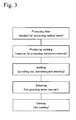
Fig. 3 is a procedural flow chart for producing a composite material member of
the present invention.
Fig. 4 is a sectional view showing a die for producing the test piece for
estimation which is a composite material member of the present invention.
Fig. 5 is a sectional view showing a test piece for estimating impregnation
performance and adhesion performance of the composite material member of the present
invention.
Fig. 6 is a sectional view showing a test piece for estimating boundary strength
of the composite material member of the present invention.
Fig. 7 is a sectional view showing an embodiment for a testing method for
estimating boundary strength of the composite material member of the present invention.
Fig. 8 is a graph showing relationships between the boundary strength and the
volume rate of the porous material.
BEST MODE FOR CARRYING OUT THE INVENTION
Embodiments of the present invention will be explained hereinafter.
1. Production Samples
A procedural flow chart for production samples No. 1 to 24 shown in Table 1 is
shown in Fig. 3. First, by using a method for extracting melted metal disclosed in
Japanese Patent Publication No. 3176833, fibers having a diameter of 40 µm were
produced by using SUS 430, the obtained fibers were unwoven, whereby webbing
having coating weight of 140 g/m
2 were produced. Directions of the fibers were
randomly in a surface lamination direction. The webbings were punched out into a
shape for testing by a pressing machine, and a predetermined number of the punched
webbings were laminated, whereby laminated bodies were obtained. The laminated
bodies were pressed so as to obtain porous materials having volume rates shown in Table
1. The volume rate (%) is a value showing compactness of the porous material which
is shown by the following formula.
Vf = (true volume / apparent volume) × 100
| Sample No. | porous material specifications | evaluation result |
| | material | plate thickness t(mm) | volume rate Vf | impregnation performance | adhesion performance | boundary strength |
| | | | (%) | | | (Mpa) |
| Sample 1 | SUS 430 fiber | 0.5 | 50 | ○ | × | - |
| Sample 2 | SUS 430 fiber | 0.5 | 60 | ○ | × | - |
| Sample 3 | SUS 430 fiber | 0.5 | 70 | ○ | × | - |
| Sample 4 | SUS 430 fiber | 1 | 10 | ○ | × | - |
| Sample 5 | SUS 430 fiber | 1 | 20 | ○ | × | - |
| Sample 6 | SUS 430 fiber | 1 | 30 | ○ | ○ | 60 |
| Sample 7 | SUS 430 fiber | 1 | 40 | ○ | ○ | 75 |
| Sample 8 | SUS 430 fiber | 1 | 50 | ○ | ○ | 95 |
| Sample 9 | SUS 430 fiber | 1 | 60 | ○ | ○ | 140 |
| Sample 10 | SUS 430 fiber | 1 | 70 | × | - | - |
| Sample 11 | SUS 430 fiber | 2 | 10 | ○ | Δ | 20 |
| Sample 12 | SUS 430 fiber | 2 | 20 | ○ | ○ | 52 |
| Sample 13 | SUS 430 fiber | 2 | 30 | ○ | ○ | 66 |
| Sample 14 | SUS 430 fiber | 2 | 40 | ○ | ○ | 77 |
| Sample 15 | SUS 430 fiber | 2 | 50 | ○ | ○ | 100 |
| Sample 16 | SUS 430 fiber | 2 | 60 | Δ | ○ | 144 |
| Sample 17 | SUS 430 fiber | 2 | 70 | × | - | - |
| Sample 18 | SUS 430 fiber | 3 | 10 | ○ | Δ | 42 |
| Sample 19 | SUS 430 fiber | 3 | 20 | ○ | ○ | 64 |
| Sample 20 | SUS 430 fiber | 3 | 30 | ○ | ○ | 68 |
| Sample 21 | SUS 430 fiber | 3 | 40 | ○ | ○ | 84 |
| Sample 22 | SUS 430 fiber | 3 | 50 | Δ | ○ | 98 |
| Sample 23 | SUS 430 fiber | 3 | 60 | Δ | ○ | 146 |
| Sample 24 | SUS 430 fiber | 3 | 70 | × | - | - |
| Sample 25 | SUS 430 fiber | 1 | 0.5 (main material side) | 20 | ○ | ○ | 122 |
| 0.5 (secondary material side) | 60 |
| Sample 26 | SUS 430 fiber | 1 | 0.5 (main material side) | 20 | ○ | ○ | 134 |
| 0.5 (secondary material side) | 70 |
| Sample 27 | SUS 430 fiber | 1 | 0.5 (main material side) | 20 | × | - | - |
| 0.5 (secondary material side) | 80 |
| Sample 28 | Ni foamed metal | 2 | 20 | ○ | ○ | 44 |
| Sample 29 | Ni foamed metal | 2 | 40 | ○ | ○ | 65 |
The porous materials preliminarily compressed at a volume rate shown in Table
1 were set on the SUS 430 used as the secondary material, and these materials were
sintered at 1100 °C for 2 hours (by compression by its own weight) without loading in a
vacuum furnace, whereby compacts were obtained. In this step, the secondary material
and porous material, and the porous material and the porous material were joined by
diffusion. The obtained compacts as mentioned above were preheated at 300 °C, and
were set on an undersurface of the die 2 shown in Fig. 4, and A1 alloy ADC 12 (JIS 2118)
which was a main material was poured from a fill pot 21 of melted metal at 750 °C and
600 MPa, whereby test pieces of composite material member were produced
(die-casting). According to the method, production efficiency is high since it is not
necessary for the porous material to be sintered in a condition of pressing the material.
In the method for producing the samples 1 to 24, the process in which the porous
material is preliminarily compressed can be omitted, and the porous material can be
compressed in sintering of the porous material and the secondary material so as to obtain
predetermined Vf.
The samples Nos. 25 to 27 were obtained by respectively sintering two kind of
porous materials having different Vf in the step of obtaining predetermined Vf by
pressing the porous materials, in producing method for the samples Nos. 1 to 24, and by
sintering again in a condition of laminating the porous materials on the secondary
material in descending order of Vf in the step of producing the compacts.
The samples Nos. 28 and 29 were obtained by using Ni foamed metal having a
coating weight of 140 g/m2 (Cermet, produced by Sumitomo Electric Industries, Ltd.)
and by performing of molding, sintering, and casting shown in the Fig. 3.
2. Examination Contents
Impregnation performance, adhesion performance, and boundary strength were
estimated at three levels. Fig. 5 shows a specifications of the test piece for estimation of
impregnation performance and adhesion performance, and a = 20 mm, b =100 mm, P =
30 mm, and q = 15 mm in Fig. 5.
The impregnation performance means an estimated performance which shows a
degree of impregnating the porous material into the main material and is observed by
scanning Electron Microscopy (SEM).
The adhesion performance means an estimated performance in which the
presence of interstitial spaces in the boundary face between the secondary material and
the main material is estimated, and the adhesion performance was observed by SEM.
The joining strength at the boundary face was estimated by joining strength at the
boundary face between the secondary material and the main material by a shearing test.
Fig. 7 shows an embodiment for a method for a shearing test in which a test
piece of a composite material member having a shape shown in Fig. 6 is held between
parts of a fixed jig 31, and a shearing jig 32 is moved in the pressurization direction 33 at
0.5 mm/min, whereby shearing stress is measured, and the measured value is considered
as the joining strength in the boundary face.
3. Test Result
The test result is shown in Table 1. The meaning of the symbols in the
estimation result column will be explained hereinafter.
The impregnation performance was estimated at three levels.
The adhesion performance was estimated at three levels.
4. Estimation
Fig. 1 is a sectional view showing an example of the composite material member
1 of an embodiment of the present invention. In the construction of the composite
material member shown in Fig. 1, a main material 11 (SUS 430) and a secondary
material 12 (ADC 12) are joined on the joining portion 14, and metal fibers 13 (SUS
430) are arranged in the boundary portion. It was confirmed that the secondary
material 12 and the metal fiber 17 were joined by diffusion in diffusion joining portion
16, and metal fiber 13 and metal fiber 13 were joined by diffusion in diffusion joining
portion 17.
Fig. 2 is a sectional view showing an example of the composite material member
1 of an embodiment of the present invention similar to the example shown in Fig. 1. In
the example shown in the Fig. 2, interstitial space 15 occurs by peeling the boundary
face 14. The condition of the boundary face is defined as the defective adhesion. The
interstitial space 15 occurs by peeling the boundary face due to large strain based on
difference in coefficient of thermal expansion.
The samples Nos. 1 to 24 are a sample group having common point in which Vf
of porous material is uniform in the same sample. Influence for the boundary strength
in the case of changing the plate thickness and the Vf of these samples is shown in Fig. 8.
In Fig. 8, t1 = 1 mm, t2 = 2 mm, and t3 = 3 mm in the plate thickness. As for
comparison of the influence of the plate thickness, when the plate thickness is greater, the
boundary strength is obviously larger in a range of Vf of not more than 40. However, if
the plate thickness is greater, the boundary strength is not obviously larger as well in
range of Vf of not less than 50. As for the influence of the Vf, when the Vf is larger, the
boundary strength is obviously larger. Judging from these tendencies, when the
boundary strength must be increased, Vf is increased. However, increasing the plate
thickness is effective for the boundary strength in range of a small Vf (less than 30), and
the increasing the plate thickness is not effective for the boundary strength in a range of a
large Vf. Therefore, it is confirmed that the closest element for the boundary strength is
Vf in the vicinity of the joining face, and when the plate thickness is not less than 1 mm
and less than 2 mm, Vf is necessarily 30 at a minimum, and when Vf is larger, the
boundary strength is larger, and when the Vf in the vicinity of the joining face is further
smaller (not less than 20), the small Vf can be covered by the plate thickness (not less
than 2 mm). However, in contrast, it is confirmed that when the Vf is set to be not less
than 70, high impregnation performance and adhesion performance cannot be obtained
(samples Nos. 10,17, and 24), and casting cannot be preferably performed. This is
because when the Vf is excessively increased, it is difficult for the main material to
impregnate into the porous material in casting in the producing conditions. Moreover,
the plate thickness is excessively small such as less than 1 mm (samples Nos. 1 to 3), it is
confirmed that even when the Vf is increased, the effect of existence of the porous
material in the boundary area between the main material and the secondary material is
not apparent. Therefore, it is confirmed that, in the porous material of the present
invention, when the plate thickness is not less than 1 mm and less than 2 mm, preferable
boundary strength can be obtained in the case of setting the Vf to be 30 to 60, and when
the plate thickness is not less than 2 mm, desirable boundary strength can be obtained in
the case of setting the Vfto be 20 to 60.
The samples Nos. 25 to 27 are obtained by laminating 2 kinds of the porous
materials having different Vf. In these examples, conflicting performances of high
impregnation performance of the main material in casting in the case of small Vf and
high boundary strength in the case of large Vf are balanced. Even when the whole
plate thickness is 1 mm, preferable boundary strength can be obtained. For example, in
sample No. 25, the average of Vf is 40, and the boundary strength (122 MPa) of the
sample No. 25 is 1.6 times of that (75 MPa) of the sample No. 7 which has
corresponding plate thickness of 1 mm and Vf of 40. However, the Vf exceeds 80,
defective impregnation occurs in the condition of the producing condition.
The samples Nos. 28 and 29 are obtained by using foamed metal as a porous
material. The boundary strengths of the samples Nos. 28 and 29 are lower than those
of the samples Nos. 12 and 14 having plate thickness and Vf equal to those of the
samples Nos. 28 and 29. Because mesh of the foamed metal is coarse and the
secondary materials are different between the samples Nos. 12 and 14 and the samples
Nos. 28 and 29.
5. Changed example
Light metal which is the main material of the present invention means aluminum,
magnesium, alloy made of at least one of these metals and another metal. However, the
light metal is not limited in the range of the above-mentioned metal and alloy.
The secondary material of the present invention can be any material which can
cover the problems of the light metal. For example, when mechanical strength such as
tension, compression, shear, and friction must be covered, it is preferable for the
secondary material to use cast iron, iron steel, stainless steel, Fe-Cr-based alloy, Ni-based
alloy. When the thermal strength must be covered, it is preferably for the secondary
material to use various ceramics. However, the secondary material is not limited in the
range of the above-mentioned material.
As property of the porous material of the present invention, it is preferably to join
the porous material and the porous material, and further porous material and the
secondary material for diffusion. However, the property of the porous material is not
limited in the range of the above-mentioned property. Any porous material having
properties in which the porous material and the secondary material can be joined by
binding or brazing can be used. As the thermal property, coefficient of thermal
expansion of the porous material is preferably equal to that of the secondary material.
Therefore, the porous material is more preferably composed of the same material of the
secondary material.
In the samples Nos. 1 to 5, thermal strain cannot be completely moderated in the
producing condition, whereby the defective adhesion is observed. In another
producing condition in which pressure is held for about 2 minutes after injection of
melted metal, and pressure is also applied in the quenching, the adhesion performance is
improved, and test pieces having preferable joining face can be obtained. Additionally,
in these methods, it is inevitable that production facilities are expensive and the
production process is time consuming.
In the samples Nos. 10, 17, and 24, defective impregnation occurs. However,
test pieces having preferable impregnation performance can be obtained by preheating
the compact to 700°C or increasing pressure for pouring the melted metal at 100 MPa.
Additionally, these preprocessing and casting conditions bring high production cost.