EP1574262B1 - Cleaning apparatus - Google Patents
Cleaning apparatus Download PDFInfo
- Publication number
- EP1574262B1 EP1574262B1 EP05251429A EP05251429A EP1574262B1 EP 1574262 B1 EP1574262 B1 EP 1574262B1 EP 05251429 A EP05251429 A EP 05251429A EP 05251429 A EP05251429 A EP 05251429A EP 1574262 B1 EP1574262 B1 EP 1574262B1
- Authority
- EP
- European Patent Office
- Prior art keywords
- tank
- cleaning
- cleaning apparatus
- lid
- fluid
- Prior art date
- Legal status (The legal status is an assumption and is not a legal conclusion. Google has not performed a legal analysis and makes no representation as to the accuracy of the status listed.)
- Expired - Lifetime
Links
- 238000004140 cleaning Methods 0.000 title claims abstract description 100
- 239000012530 fluid Substances 0.000 claims abstract description 35
- 239000007921 spray Substances 0.000 claims description 29
- 238000000605 extraction Methods 0.000 claims description 6
- 239000003973 paint Substances 0.000 claims description 5
- 238000000034 method Methods 0.000 claims description 3
- 230000008878 coupling Effects 0.000 claims 2
- 238000010168 coupling process Methods 0.000 claims 2
- 238000005859 coupling reaction Methods 0.000 claims 2
- 239000000463 material Substances 0.000 description 5
- 238000005086 pumping Methods 0.000 description 2
- 238000007592 spray painting technique Methods 0.000 description 2
- OKTJSMMVPCPJKN-UHFFFAOYSA-N Carbon Chemical compound [C] OKTJSMMVPCPJKN-UHFFFAOYSA-N 0.000 description 1
- 230000003213 activating effect Effects 0.000 description 1
- 230000009286 beneficial effect Effects 0.000 description 1
- 230000015572 biosynthetic process Effects 0.000 description 1
- 229910052799 carbon Inorganic materials 0.000 description 1
- 239000012459 cleaning agent Substances 0.000 description 1
- 238000011109 contamination Methods 0.000 description 1
- 239000006185 dispersion Substances 0.000 description 1
- 230000009977 dual effect Effects 0.000 description 1
- 230000000694 effects Effects 0.000 description 1
- 238000005755 formation reaction Methods 0.000 description 1
- 239000004519 grease Substances 0.000 description 1
- 239000007788 liquid Substances 0.000 description 1
- 230000007246 mechanism Effects 0.000 description 1
- 239000002184 metal Substances 0.000 description 1
- 230000008569 process Effects 0.000 description 1
- 230000008439 repair process Effects 0.000 description 1
- 238000002791 soaking Methods 0.000 description 1
- 239000002904 solvent Substances 0.000 description 1
- 238000005507 spraying Methods 0.000 description 1
- 239000000126 substance Substances 0.000 description 1
- 239000011800 void material Substances 0.000 description 1
Images


Classifications
-
- B—PERFORMING OPERATIONS; TRANSPORTING
- B08—CLEANING
- B08B—CLEANING IN GENERAL; PREVENTION OF FOULING IN GENERAL
- B08B3/00—Cleaning by methods involving the use or presence of liquid or steam
- B08B3/02—Cleaning by the force of jets or sprays
-
- B—PERFORMING OPERATIONS; TRANSPORTING
- B08—CLEANING
- B08B—CLEANING IN GENERAL; PREVENTION OF FOULING IN GENERAL
- B08B3/00—Cleaning by methods involving the use or presence of liquid or steam
- B08B3/04—Cleaning involving contact with liquid
-
- B—PERFORMING OPERATIONS; TRANSPORTING
- B05—SPRAYING OR ATOMISING IN GENERAL; APPLYING FLUENT MATERIALS TO SURFACES, IN GENERAL
- B05B—SPRAYING APPARATUS; ATOMISING APPARATUS; NOZZLES
- B05B15/00—Details of spraying plant or spraying apparatus not otherwise provided for; Accessories
- B05B15/50—Arrangements for cleaning; Arrangements for preventing deposits, drying-out or blockage; Arrangements for detecting improper discharge caused by the presence of foreign matter
- B05B15/55—Arrangements for cleaning; Arrangements for preventing deposits, drying-out or blockage; Arrangements for detecting improper discharge caused by the presence of foreign matter using cleaning fluids
-
- B—PERFORMING OPERATIONS; TRANSPORTING
- B08—CLEANING
- B08B—CLEANING IN GENERAL; PREVENTION OF FOULING IN GENERAL
- B08B3/00—Cleaning by methods involving the use or presence of liquid or steam
- B08B3/006—Cabinets or cupboards specially adapted for cleaning articles by hand
Definitions
- This invention relates to cleaning tools, and in particular to an apparatus for cleaning spray guns.
- Paint spray guns are widely used in automotive repair shops and other industries where spray painting is carried out. These spray guns must be cleaned regularly if they are to have a reasonable service life. Furthermore, spray guns must be thoroughly cleaned within a limited time frame following use, otherwise the paint tends to solidify, making the spray gun exceedingly difficult to clean.
- spray gun cleaning apparatus There are many examples of spray gun cleaning apparatus.
- the most commonly used apparatus comprise a cabinet which includes a drain, a fluid supply, a fluid dispersion means and fluid collector.
- the fluid supply and fluid collector are consumables, brought to and removed from the machine.
- the spray gun cleaning apparatus must itself be cleaned periodically. This gives rise to a number of problems.
- WO97/3567 describes equipment for cleaning spray guns in which an electric pump is used to convey cleaning liquid to an through spray nozzles.
- a spray gun cleaning apparatus is also known from US 2004/0103933 .
- the apparatus is characterised by the washer apparatus providing clean solution throughout each wash cycle.
- US 5265633 describes an apparatus manufactured of materials capable of withstanding aggressive chemicals and used for cleaning parts of mechanisms requiring the removal of oil, grease, dirt, carbon, baked on grime and the like.
- Nonc of the spray gun cleaning apparatus described in the above-mentioned patent information addresses the problems previously set out
- a cleaning apparatus 1 comprises a cabinet structure 2 upon which a cleaning tank 3 is removably mounted.
- the cabinet structure 2 further includes a thinners store 4 covered by a removable plate 5.
- the removable plate 5 includes a handle 6 and four spaced apart key hole slots 7, which co-operate with pins mounted on the cabinet structure 2 to hold the removable plate in place.
- Mounted on one side of the cabinet structure are compressed air services in the form of a hose connection 9 for connection to a supply of compressed air (not shown) and a compressed air gun 10 connected to a compressed air outlet 11 by means of a flexible hose 12.
- the cleaning apparatus 1 further includes an extractor unit 8, which is described in greater detail with reference to Figures 7a to 7c .
- the lid 13 of tank 3 is open, whereas in Figure 1b the said lid 13 is closed.
- the lid 13 is held in the lifted position illustrated in Figure 1a by means of engagement between sides 14 of said lid 13 and a clip 15.
- the sides 14 are fabricated from a material having at least some resilience.
- the lid 13 is fabricated such that the in the closed position illustrated in Figure 1b the sides 14 press against sides 17 of the tank 3. As the lid is opened, the sides 14 ride over the bracket 15. When the edge 18 of the side 14 has passed over the bracket 15, the said edge 18 is aligned with an opening provided by the bracket. The lid 13 is then pulled slightly as if to close said lid 13, bringing the edge 18 into engagement with the bracket 15.
- the switch bank 80 which includes a hand wash switch 81, a clean rinse switch 82, a timer switch 84 (see Figure 2d ), and cover plate 83 to protect the switches from unintentional switching.
- Figures 2a to 2d illustrate the steps for removing the tank 3 from the cleaning apparatus 1.
- FIG 2c the tank 3 is in the process of being removed from the cabinet structure 2. Removal of the tank 3 is achieved by pulling the lower front part of the tank 3 forwards and upwards so that the tank rotates about a point X where the tank 3 engages with the extractor unit 8. As the tank rotates a corner 21 of the tank slides on a track 24 of the cabinet structure 2.
- the tank 3 is fully removed from the cabinet structure 2.
- the tracks 24 on which the base 26 of the tank 3 slides and rests are formed from angle sections, with the leading edge of each track 24 being provided with a chamfer 25 to facilitate easy alignment of the tank 3 to the cabinet structure 2 when re-fitting the tank 3 to the cabinet structure 2.
- a ledge 23 is provided in the upper rear part of the tank 3. This ledge 23 engages with the underside of the extractor 8 to provide an effective seal between the tank 3 and the extractor 8 when the cleaning apparatus 1 is in the configurations illustrated in Figures 2a and 2b .
- FIG. 3a there is shown a stack of three tanks 3.
- the tanks 3 are shown spaced apart.
- the middle tank 3 in Figure 3a it can be seen that the wall 17 extends beyond the upper surface of lid 13 by a small distance.
- the upper tank 3 sits on the middle tank 3, which in turn sits on the lower tank 3, the base 26 of a tank 3 sitting on the lid 13 of the tank 3 below.
- a tank 3 stacked on top of another tank 3 is constrained from lateral movement by the extension of walls 17 beyond the upper surface of lid 13.
- Each tank 3 that is stacked on top of another tank 3 is constrained from longitudinal movement by pins 22 which engage with the slots 19 previously described with reference to Figure 2b .
- the slots 19 therefore fulfil dual functions. First, they form part of the lid hinge, and second they provide for the safe stacking of the tanks 3.
- the tank 3 is illustrated in greater detail in Figures 4a to 4c .
- the tank 3 comprises a chassis 27 strengthened by substantially U shaped members 28 disposed adjacent walls 17 of the tank 3.
- the width of these U shaped members corresponds substantially to the width of tracks 24, and it is the lower parts of the U shaped members that rest on the said tracks.
- the chassis 27 mounts a base plate 33 in which a drain 32 is located.
- Located in each corner of the tank 3 is a pipe 34 having outlet nozzles 35 (numbered on one pipe only for the sake of clarity).
- Each tube 34 is fluidly connected to a tube mount 36.
- a perforated plate 29 rests on the tube mounts 36 such that a void exists between the perforated plate 29 and the base plate 33.
- the perforated plate 29 is provided with edge formations 30, 31 which essentially consist of folded metal, and serve to strengthen the said plate.
- edge formations 30, 31 which essentially consist of folded metal, and serve to strengthen the said plate.
- a piece of filter material is place beneath the perforated plate 29, and another perforated plate is placed beneath the filter material. Fluid exiting through the nozzles 35 and 37 passes through the first perforated plate 29, through the filter material, and the second perforated plate to gather on base plate 33 to exit through drain 32.
- drums 40, 41 are located in the fluid store 4.
- drum 40 contains unused clean thinners fluid
- drum 41 contains used dirty thinners fluid.
- the used thinners fluid contained in drum 41 is recycled and rc-used for the first part of a cleaning cycle, and the clean thinners fluid from drum 40 is used for the final rinse cycle.
- the old drums 40 and 41 are removed, with the old drum 40 that has been removed becoming the new drum 41, and a new drum 40 is installed.
- the new drum 40 and old drum 40 (new drum 41) are each approximately half full.
- a pipe 42 extends from the drum 40 to a shut-off valve 43, which is in fluid connection with a pipe 44 that is connected to a clean rinse nozzle (see Figure 8 ) the pipes 34.
- a pipe 45 extends from the drum 41 to a shut-off valve 46, which is in fluid connection with a pipe 47 that is connected to the pipes 34.
- Another pipe (not shown) extends from drain 32 to the drum 40.
- the cleaning apparatus 1 includes a hose connection 9 for connection to a supply of compressed air (not shown) to the apparatus. Compressed air is the power source for the apparatus as will be described in greater detail with reference to Figure 9 .
- the apparatus also includes an air gun 10 connected to a compressed air outlet 11 by means of a flexible hose 12.
- the air gun is provided as many spray gun operators like to use compressed air to assist in cleaning their spray guns.
- the air gun 10 includes a hook 48, which hooks onto a corresponding hook 49 protruding from the cabinet structure 2. The air gun is conveniently positioned for use by an individual using the cleaning apparatus 1.
- Figure 7a to 7c illustrate the extractor unit 8 which comprises a housing 50 on top of which is mounted a chamber 51 having an outlet 52.
- the housing 50 lies above the rear part of the cleaning tank 3.
- the housing 50 includes a pair of spaced apart apertures 57 which receive tubular elements extending downwardly from the housing 50. Seals 61 ensure that air extracted from the tank 3 does not leak into the housing 50.
- Extraction of air from the tank 3 is achieved by means of an air jet 60.
- the air jet 60 is connected to the supply of compressed air by means of pipe 54.
- the air jet 60 functions as a venturi, creating a region of high velocity and low pressure air at the top of the chamber 51. This has the effect of drawing air in the tank through the chamber 51 and out of the outlet 52.
- the housing 50 includes an element 58 which mounts a cut-off switch 59.
- the cut-off switch 59 is on when the lid 13 is up, because any contamination can escape to atmosphere, and off when the lid 13 is down.
- the switch 59 is turned on and off by engagement/disengagement of a part of the lid 13 with the switch 59.
- the cleaning fluid circuit comprises a drum 40 containing clean thinners fluid and a drum 41 containing recycled thinners fluid.
- Inlets of two pumps 71 and 73 are connected by pipes 72 and 74 respectively to the drum 41, each pipe 72, 74 having a filter 70 at the drum end.
- Each pump 71, 73 has an outlet connected to a nozzle located in the tank 3.
- the pump 71 is connected by a pipe 75 to connectors 76 which attach to pipes 34 to deliver fluid to nozzles 35 and 37.
- the outlet of pump 73 is connected to a hand wash nozzle 77, which, in use, is located in the tank 3 towards the rear thereof.
- the drum 40 containing clean thinners fluid is connected by a pipe 42 to a clean rinse nozzle 78, which, in use, is located in the tank 3 towards the rear thereof. Clean thinners fluid is drawn from the drum 40 to the nozzle 78 due to a partial vacuum created in a chamber in the clean rinse block by the admission of air through a jet in the same clean rinse block when the tank lid is open and the clean rinse switch 82 is operated.
- Outlet 32 of the tank 3 is fluidly connected to the drum 41 by means of a shut off valve 79.
- the shut off valve 79 is open so that spent cleaning fluid that has passed through the filter elements in the base of the tank 3 return to the thinners fluid drum 41.
- one cleaning operation involves soaking items placed in the tank 3. In order to run this cycle the valve 79 must be closed.
- the pressurised air system includes: a compressed air supply connection 9, the pumps 71 and 73, both of which are powered by compressed air, an on/off valve 85, an air filter 86, an air gun 10, a timer valve 84, a hand wash switch 81, a clean rinse switch 82, an pressure regulator valves 87 and 88.
- the on/off valve 85 is opened and air flows through the filter 86 to supply the air gun 10 and the switch 59.
- the switch 59 is open and compressed air flows to the nozzle 60 and to the hand wash switch 81. If the hand wash switch 81 is opened, air flows via pressure regulator 87 to the pump 73, thereby pumping thinners fluid from the drum 41 to the hand wash outlet nozzle 77.
- the lid open and the switch 59 open compressed air is delivered to the clean rinse switch 82.
- the clean rinse switch 82 is opened, air is allowed to pass to the clean rinse outlet 78 and within this outlet through a jet and into a chamber. A partial vacuum is created in the chamber drawing thinners fluid from the clean thinners drum 40 into the chamber, where it is atomised and forced out of the clean rinse outlet 78.
- shut-off valve 79 To operate in "soak” mode, the operator closes shut-off valve 79. Any of the “automatic”, “manual wash”, and “clean rinse modes” can be used in "soak” mode.
- the cleaning apparatus of the invention is particularly advantageous as it allows the apparatus to be cleaned away from the place where the apparatus is located. This is achieved by having a tank 3 which is detachable from the rest of the machine.
- This provides a number of advantages: First, the apparatus downtime is reduced from around 30 to 45 minutes to 5 to 10 minutes, resulting in less down time for spray gun operators. Second, because the time taken to service the cleaning apparatus is only 5 to 10 minutes compared to around 30 to 45 minutes for known apparatus, a service engineer can service many more machines in a day. Third, the actual operation of cleaning a tank does not require a person having the same skill level as a service engineer. As such the cost of cleaning can be reduced by using labour having a skill level appropriate for the task in hand.
- a simple stacking system is provided. This is beneficial for both safe transportation and storage of the tanks.
- Another embodiment of the invention provides a convenient means for holding the tank lid in its open position.
Landscapes
- Cleaning By Liquid Or Steam (AREA)
- Confectionery (AREA)
- Automatic Analysis And Handling Materials Therefor (AREA)
- Filters For Electric Vacuum Cleaners (AREA)
- Detergent Compositions (AREA)
Abstract
Description
- This invention relates to cleaning tools, and in particular to an apparatus for cleaning spray guns.
- Paint spray guns are widely used in automotive repair shops and other industries where spray painting is carried out. These spray guns must be cleaned regularly if they are to have a reasonable service life. Furthermore, spray guns must be thoroughly cleaned within a limited time frame following use, otherwise the paint tends to solidify, making the spray gun exceedingly difficult to clean.
- There are many examples of spray gun cleaning apparatus. The most commonly used apparatus comprise a cabinet which includes a drain, a fluid supply, a fluid dispersion means and fluid collector. The fluid supply and fluid collector are consumables, brought to and removed from the machine.
- The spray gun cleaning apparatus must itself be cleaned periodically. This gives rise to a number of problems. First, whilst the apparatus is being cleaned, it is not possible to use the same apparatus for cleaning spray guns, and hence spray gun operators may be forced to stand idle whilst waiting to clean their spray guns. Second, spray guns and ancillary equipment must be cleaned within 10 minutes of ceasing spraying. If an operator has to wait longer than this threshold time, the paint in his gun may "go off", making the gun particularly difficult to clean. Third, because the spray gun cleaning apparatus must be dismantled for cleaning, only a properly trained service engineer can carry out the cleaning operation. Fourth, because known spray gun cleaning apparatus require on site cleaning, the number of apparatus that a service engineer can attend to in any one day is limited by the amount of time he must spend cleaning apparatus. Fifth, the cleaning agents used to clean the apparatus must be acceptable for use in a spray shop.
- A number of patents and patent applications relate to spray gun cleaning apparatus.
WO97/3567 - Another known spray gun cleaning apparatus is described in
US 6,647,997 . The apparatus described in this patent is characterised in not requiring hand operation of taps and the like. - Another known spray gun cleaning apparatus is described in
US 4,827,955 . In this patent, a suction system is used to expose the spray gun to a vacuum fox cleaning. This apparatus avoids solvent being sprayed into the atmosphere. - A spray gun cleaning apparatus is also known from
US 2004/0103933 . In this patent the apparatus is characterised by the washer apparatus providing clean solution throughout each wash cycle. - Another spray gun cleaning apparatus is described in
EP 1327485 . In this patent the apparatus is characterised by the presence of a partially submerged rotatable brush. -
US 5265633 describes an apparatus manufactured of materials capable of withstanding aggressive chemicals and used for cleaning parts of mechanisms requiring the removal of oil, grease, dirt, carbon, baked on grime and the like. - Nonc of the spray gun cleaning apparatus described in the above-mentioned patent information addresses the problems previously set out
- It would therefore be desirable to provide an improved cleaning apparatus, which is suitable for the cleaning of spray guns.
- According to one aspect of the invention there is provided a cleaning apparatus as specified in
Claim 1. - According to a second aspect of the invention there is provided a method of cleaning spray painting equipment as specified in Claim 20.
- In the drawings, which illustrate preferred embodiments of the invention, and are by way of example
-
Figure 1a is a schematic representation of a cleaning apparatus according to the invention with the lid open; -
Figure 1b is a schematic representation of the cleaning apparatus illustrated inFigure 1a with the lid closed; -
Figure 2a is a schematic representation of a cleaning apparatus according to the invention in assembled configuration; -
Figure 2b is a schematic representation of the cleaning apparatus illustrated inFigure 2c with the lid removed; -
Figure 2c is a schematic representation of the cleaning apparatus illustrated inFigures 2a and 2b with the cleaning tank partially removed; -
Figure 2d is a schematic representation of the cleaning apparatus illustrated inFigures 2a to 2c with the cleaning tank fully removed; -
Figure 3a is an exploded view of a stack of three cleaning tanks forming part of the cleaning apparatus according to the invention; -
Figure 3b is an exploded view of a part of a connecting arrangement according to the invention; -
Figure 3c illustrates the three cleaning tanks ofFigure 3a in stacked configuration; -
Figure 3d is an exploded view of the connecting arrangement partially illustrated inFigure 3b ; -
Figure 4a is a schematic illustration of the cleaning tank forming part of the cleaning apparatus according to the invention; -
Figure 4b is a schematic representation of the cleaning tank illustrated inFigure 4a and showing additional elements of the tank; -
Figure 4c is an exploded view of a base portion of the tank illustrated inFigures 4a and 4b ; -
Figure 5a is a schematic representation of cleaning apparatus according to the invention; -
Figure 5b is a schematic representation of the cleaning apparatus illustrated inFigure 5a with a cover removed; -
Figure 5c is a cut-away view of the cleaning apparatus illustrated inFigures 5a and 5b ; -
Figure 5d is detail view of a first valve forming part of the cleaning apparatus illustrated inFigure 5c ; -
Figure 5e is a detail view of a second valve forming part of the cleaning apparatus illustrated inFigure 5c ; -
Figure 6a is a schematic representation of cleaning apparatus according to the invention; -
Figure 6b is a detailed view of pressurised air connector; -
Figure 6c is a detailed view of a pressurised air gun; -
Figure 7a is a schematic representation of an extractor unit of the cleaning apparatus according to the invention; -
Figure 7b is an exploded view of the extractor unit illustrated inFigure 7a ; -
Figure 7c is a cross-sectional elevation of the extractor unit illustrated inFigure 7a ; -
Figure 8 is a schematic representation of the cleaning fluid hydraulics of the cleaning apparatus according to the invention; and -
Figure 9 is a schematic representation of the pressurised air hydraulics of the cleaning apparatus according to the invention. - Referring now to
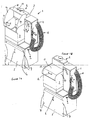
Figures 1a and 1b , acleaning apparatus 1 comprises acabinet structure 2 upon which acleaning tank 3 is removably mounted. Thecabinet structure 2 further includes athinners store 4 covered by aremovable plate 5. Theremovable plate 5 includes a handle 6 and four spaced apartkey hole slots 7, which co-operate with pins mounted on thecabinet structure 2 to hold the removable plate in place. Mounted on one side of the cabinet structure are compressed air services in the form of a hose connection 9 for connection to a supply of compressed air (not shown) and acompressed air gun 10 connected to acompressed air outlet 11 by means of aflexible hose 12. Thecleaning apparatus 1 further includes anextractor unit 8, which is described in greater detail with reference toFigures 7a to 7c . InFigure 1a thelid 13 oftank 3 is open, whereas inFigure 1b the saidlid 13 is closed. - The
lid 13 is held in the lifted position illustrated inFigure 1a by means of engagement betweensides 14 of saidlid 13 and aclip 15. Thesides 14 are fabricated from a material having at least some resilience. Thelid 13 is fabricated such that the in the closed position illustrated inFigure 1b thesides 14 press againstsides 17 of thetank 3. As the lid is opened, thesides 14 ride over thebracket 15. When the edge 18 of theside 14 has passed over thebracket 15, the said edge 18 is aligned with an opening provided by the bracket. Thelid 13 is then pulled slightly as if to close saidlid 13, bringing the edge 18 into engagement with thebracket 15. - Also shown in
Figure 1a is the switch bank 80, which includes ahand wash switch 81, a clean rinseswitch 82, a timer switch 84 (seeFigure 2d ), and cover plate 83 to protect the switches from unintentional switching. -
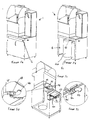
Figures 2a to 2d illustrate the steps for removing thetank 3 from thecleaning apparatus 1. - In
Figure 2a the tank is situated in the cleaning apparatus with thelid 13 closed. - In
Figure 2b thelid 13 is shown removed from thecleaning apparatus 1. In thesides 17 of thetank 3 are provided withslots 19 in which pins 20 of thelid 13 locate. - In
Figure 2c thetank 3 is in the process of being removed from thecabinet structure 2. Removal of thetank 3 is achieved by pulling the lower front part of thetank 3 forwards and upwards so that the tank rotates about a point X where thetank 3 engages with theextractor unit 8. As the tank rotates acorner 21 of the tank slides on atrack 24 of thecabinet structure 2. - In
Figure 2d thetank 3 is fully removed from thecabinet structure 2. Thetracks 24 on which thebase 26 of thetank 3 slides and rests are formed from angle sections, with the leading edge of eachtrack 24 being provided with achamfer 25 to facilitate easy alignment of thetank 3 to thecabinet structure 2 when re-fitting thetank 3 to thecabinet structure 2. Aledge 23 is provided in the upper rear part of thetank 3. Thisledge 23 engages with the underside of theextractor 8 to provide an effective seal between thetank 3 and theextractor 8 when thecleaning apparatus 1 is in the configurations illustrated inFigures 2a and 2b . - Referring now to
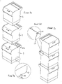
Figures 3a to 3d , there is shown a stack of threetanks 3. InFigure 3a thetanks 3 are shown spaced apart. Looking at themiddle tank 3 inFigure 3a , it can be seen that thewall 17 extends beyond the upper surface oflid 13 by a small distance. In the configuration shown inFigure 3c , theupper tank 3 sits on themiddle tank 3, which in turn sits on thelower tank 3, thebase 26 of atank 3 sitting on thelid 13 of thetank 3 below. Atank 3 stacked on top of anothertank 3 is constrained from lateral movement by the extension ofwalls 17 beyond the upper surface oflid 13. Eachtank 3 that is stacked on top of anothertank 3 is constrained from longitudinal movement bypins 22 which engage with theslots 19 previously described with reference toFigure 2b . Theslots 19 therefore fulfil dual functions. First, they form part of the lid hinge, and second they provide for the safe stacking of thetanks 3. - The
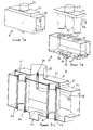
tank 3 is illustrated in greater detail inFigures 4a to 4c . Referring now toFigure 4b , thetank 3 comprises achassis 27 strengthened by substantially U shapedmembers 28 disposedadjacent walls 17 of thetank 3. The width of these U shaped members corresponds substantially to the width oftracks 24, and it is the lower parts of the U shaped members that rest on the said tracks. Thechassis 27 mounts abase plate 33 in which adrain 32 is located. Located in each corner of thetank 3 is apipe 34 having outlet nozzles 35 (numbered on one pipe only for the sake of clarity). Eachtube 34 is fluidly connected to atube mount 36. Aperforated plate 29 rests on the tube mounts 36 such that a void exists between theperforated plate 29 and thebase plate 33. Theperforated plate 29 is provided withedge formations 30, 31 which essentially consist of folded metal, and serve to strengthen the said plate. In use a piece of filter material is place beneath theperforated plate 29, and another perforated plate is placed beneath the filter material. Fluid exiting through thenozzles 35 and 37 passes through the firstperforated plate 29, through the filter material, and the second perforated plate to gather onbase plate 33 to exit throughdrain 32. - Referring now to
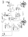
Figures 5a to 5e , drums 40, 41 are located in thefluid store 4. In thisembodiment drum 40 contains unused clean thinners fluid, whereasdrum 41 contains used dirty thinners fluid. In operation, the used thinners fluid contained indrum 41 is recycled and rc-used for the first part of a cleaning cycle, and the clean thinners fluid fromdrum 40 is used for the final rinse cycle. When the cleaning apparatus is serviced, theold drums old drum 40 that has been removed becoming thenew drum 41, and anew drum 40 is installed. Thenew drum 40 and old drum 40 (new drum 41) are each approximately half full. Apipe 42 extends from thedrum 40 to a shut-offvalve 43, which is in fluid connection with apipe 44 that is connected to a clean rinse nozzle (seeFigure 8 ) thepipes 34. Apipe 45 extends from thedrum 41 to a shut-offvalve 46, which is in fluid connection with apipe 47 that is connected to thepipes 34. Another pipe (not shown) extends fromdrain 32 to thedrum 40. - Referring now to
Figures 6a to 6c , thecleaning apparatus 1 includes a hose connection 9 for connection to a supply of compressed air (not shown) to the apparatus. Compressed air is the power source for the apparatus as will be described in greater detail with reference toFigure 9 . The apparatus also includes anair gun 10 connected to acompressed air outlet 11 by means of aflexible hose 12. The air gun is provided as many spray gun operators like to use compressed air to assist in cleaning their spray guns. As is best shown inFigure 6c , theair gun 10 includes ahook 48, which hooks onto acorresponding hook 49 protruding from thecabinet structure 2. The air gun is conveniently positioned for use by an individual using thecleaning apparatus 1. -
Figure 7a to 7c illustrate theextractor unit 8 which comprises ahousing 50 on top of which is mounted achamber 51 having anoutlet 52. In the assembledcleaning apparatus 1, thehousing 50 lies above the rear part of thecleaning tank 3. Thehousing 50 includes a pair of spaced apart apertures 57 which receive tubular elements extending downwardly from thehousing 50.Seals 61 ensure that air extracted from thetank 3 does not leak into thehousing 50. - Extraction of air from the
tank 3 is achieved by means of anair jet 60. Theair jet 60 is connected to the supply of compressed air by means ofpipe 54. Theair jet 60 functions as a venturi, creating a region of high velocity and low pressure air at the top of thechamber 51. This has the effect of drawing air in the tank through thechamber 51 and out of theoutlet 52. - The
housing 50 includes anelement 58 which mounts a cut-off switch 59. The cut-off switch 59 is on when thelid 13 is up, because any contamination can escape to atmosphere, and off when thelid 13 is down. Theswitch 59 is turned on and off by engagement/disengagement of a part of thelid 13 with theswitch 59. - Referring now to
Figure 8 , the cleaning fluid circuit comprises adrum 40 containing clean thinners fluid and adrum 41 containing recycled thinners fluid. Inlets of twopumps pipes drum 41, eachpipe filter 70 at the drum end. Eachpump tank 3. Thepump 71 is connected by apipe 75 toconnectors 76 which attach topipes 34 to deliver fluid tonozzles 35 and 37. The outlet ofpump 73 is connected to ahand wash nozzle 77, which, in use, is located in thetank 3 towards the rear thereof. - The
drum 40 containing clean thinners fluid is connected by apipe 42 to a clean rinsenozzle 78, which, in use, is located in thetank 3 towards the rear thereof. Clean thinners fluid is drawn from thedrum 40 to thenozzle 78 due to a partial vacuum created in a chamber in the clean rinse block by the admission of air through a jet in the same clean rinse block when the tank lid is open and the clean rinseswitch 82 is operated. -
Outlet 32 of thetank 3 is fluidly connected to thedrum 41 by means of a shut offvalve 79. For most cleaning operations the shut offvalve 79 is open so that spent cleaning fluid that has passed through the filter elements in the base of thetank 3 return to thethinners fluid drum 41. However, one cleaning operation involves soaking items placed in thetank 3. In order to run this cycle thevalve 79 must be closed. - Referring now to
Figure 9 , the pressurised air system includes: a compressed air supply connection 9, thepumps air filter 86, anair gun 10, atimer valve 84, ahand wash switch 81, a clean rinseswitch 82, anpressure regulator valves 87 and 88. - In use, with the a compressed air supply attached to the connection 9, the on/off valve 85 is opened and air flows through the
filter 86 to supply theair gun 10 and theswitch 59. When the lid is open, theswitch 59 is open and compressed air flows to thenozzle 60 and to thehand wash switch 81. If thehand wash switch 81 is opened, air flows viapressure regulator 87 to thepump 73, thereby pumping thinners fluid from thedrum 41 to the handwash outlet nozzle 77. Similarly, with the lid open and theswitch 59 open compressed air is delivered to the clean rinseswitch 82. When the clean rinseswitch 82 is opened, air is allowed to pass to the clean rinseoutlet 78 and within this outlet through a jet and into a chamber. A partial vacuum is created in the chamber drawing thinners fluid from the clean thinners drum 40 into the chamber, where it is atomised and forced out of the clean rinseoutlet 78. - With the
switch 59 closed, compressed is prevented from flowing to thenozzle 60 andhandwash switch 81. In this condition the extraction system is switched off, and pump 73 does not operate. Compressed air is delivered to thetimer valve 84, through a pressure regulator 88 and then to pump 71. In use, an operator sets the timer valve to give a particular period of wash, e.g. 45 seconds. The timer valve allows compressed air to pass therethrough for the selected wash period resulting in thepump 71 pumping thinners fluid from thedrum 41 to thenozzles 35, 37 for the selected period. At the end of the selected period thetimer valve 84 prevents further passage of compressed air and the pump ceases operation. - An operator opens the
lid 13, openingswitch 59 thereby activating the extraction system, the manual wash and clean rinse functions. To use the manual wash the operator switches switch 81 to the "on" position. When the manual wash is finished the operator switches switch 81 to the "off" position. - To use the clean rinse function the operator switches switch 82 to the "on" position. When the clean rinse is finished the operator switches switch 82 to the "off" position. The extraction system continues extraction until the
lid 13 is closed. - Where an operator wishes to use the automatic mode, he closes the
lid 13 and sets thetimer 84, which causes thinners fluid to be delivered to the outlet nozzles 35, 37. - To operate in "soak" mode, the operator closes shut-off
valve 79. Any of the "automatic", "manual wash", and "clean rinse modes" can be used in "soak" mode. - The cleaning apparatus of the invention is particularly advantageous as it allows the apparatus to be cleaned away from the place where the apparatus is located. This is achieved by having a
tank 3 which is detachable from the rest of the machine. This provides a number of advantages: First, the apparatus downtime is reduced from around 30 to 45 minutes to 5 to 10 minutes, resulting in less down time for spray gun operators. Second, because the time taken to service the cleaning apparatus is only 5 to 10 minutes compared to around 30 to 45 minutes for known apparatus, a service engineer can service many more machines in a day. Third, the actual operation of cleaning a tank does not require a person having the same skill level as a service engineer. As such the cost of cleaning can be reduced by using labour having a skill level appropriate for the task in hand. - Furthermore, in one embodiment of the invention a simple stacking system is provided. This is beneficial for both safe transportation and storage of the tanks.
- Additionally, another embodiment of the invention provides a convenient means for holding the tank lid in its open position.
Claims (20)
- A parts washer apparatus (1) for cleaning spray paint equipment, characterised in that the apparatus (1) comprising a structure (2) and a cleaning tank (3) removably mounted in the said structure (2), wherein the tank (3) includes at least one fluid outlet connectable to at least one fluid supply, a perforated support (29) arranged to support spray paint equipment in the tank (3) during cleaning, a drain (32) located beneath the perforated support (29) connectable to a fluid reservoir, and at least one outlet comprising at least one nozzle (35), the nozzle (35) being mounted in the tank (3) so as to direct cleaning fluid to objects to be cleaned in the tank (3), the apparatus further including an air extraction system (8).
- Cleaning apparatus as claimed in Claim 1, wherein the tank (3) includes a lid (13) moveable between an open position and a closed position.
- Cleaning apparatus as claimed in Claim 2, wherein mounting means (19, 22) removably mount the lid (13) on the tank (3).
- Cleaning apparatus as claimed in Claim 3, wherein the lid (13) is removably mounted on the tank (3) by mounting means (19, 22), said mounting means providing a hinge between the tank (3) and the lid (13).
- Cleaning apparatus as claimed in Claim 3 or 4, wherein the mounting means comprise at least one elongate slot (19) and at least one pin (20).
- Cleaning apparatus as claimed in Claim 5, wherein the tank (3) comprises two elongate slots (19), one in each side thereof, and the lid (13) is provided with two pins (20), each of the two pins engaging with a respective one of the slots.
- Cleaning apparatus as claimed in any preceding claim, wherein the said structure (2) includes at least one track (24) upon which the tank slides.
- Cleaning apparatus as claimed in any preceding claim, wherein the tank (3) includes an angled portion engagable with the or each track (24).
- Cleaning apparatus according to Claim 8, wherein with the lid (13) in its closed position the extractor system (8) is switched on, and with the lid (13) in its open position the extractor system (8) is switched off.
- A cleaning apparatus according to any preceding claim, wherein one of the removable tanks (3) is stackable on top of another removable tank (3).
- A cleaning tank as claimed in Claim 10, wherein the lower portion of each tank (3) is provided with one part of a securing means (22), and the upper portion of each tank is provided with a second part of a securing means (19), and when one tank (3) is stacked on top of another, the two parts of the securing means (19, 22) engage and respective movement in at least one plane between two stacked tanks (3) is substantially prevented.
- A cleaning tank as claimed in Claim 11, wherein one part of the securing means is a one part of a male/female coupling and the other part is the other part of a male female coupling.
- A cleaning tank as claimed in Claim 12, wherein the male part is a pin (22) and the female part is a slot (19).
- A cleaning apparatus as claimed in any preceding claim, wherein the cleaning fluid is thinners.
- A cleaning apparatus as claimed in any preceding claim, and comprising two removable cleaning fluid stores (41, 42).
- A cleaning apparatus as claimed in Claim 15, wherein fluid used in the apparatus is recycled to one of the stores.
- A cleaning apparatus as claimed in any preceding claim, further comprising at least one pump (71, 73).
- A cleaning apparatus as claimed in Claim 17, wherein the at least one pump (71, 73) is powered by compressed air.
- A cleaning apparatus according to any of Claims 2 to 18, further comprising means to hold the lid in the said open position comprising at least one slot (15) and at least one edge portion (14) of said lid (13), wherein the or each edge portion (14) is resilient, and during movement from the closed position to the open position the edge portion (14) rides over the slot (15), to be aligned therewith.
- A method of cleaning an object comprising the steps of:a. Placing the object in the tank of an apparatus as claimed in any of Claims 1 to 19;b. Selecting a wash cycle;c. Removing the object.
Applications Claiming Priority (2)
| Application Number | Priority Date | Filing Date | Title |
|---|---|---|---|
| GBGB0405337.7A GB0405337D0 (en) | 2004-03-09 | 2004-03-09 | Paint spraygun cleaner |
| GB0405337 | 2004-03-09 |
Publications (2)
| Publication Number | Publication Date |
|---|---|
| EP1574262A1 EP1574262A1 (en) | 2005-09-14 |
| EP1574262B1 true EP1574262B1 (en) | 2008-07-30 |
Family
ID=32117363
Family Applications (1)
| Application Number | Title | Priority Date | Filing Date |
|---|---|---|---|
| EP05251429A Expired - Lifetime EP1574262B1 (en) | 2004-03-09 | 2005-03-09 | Cleaning apparatus |
Country Status (4)
| Country | Link |
|---|---|
| EP (1) | EP1574262B1 (en) |
| AT (1) | ATE402765T1 (en) |
| DE (1) | DE602005008492D1 (en) |
| GB (2) | GB0405337D0 (en) |
Cited By (8)
| Publication number | Priority date | Publication date | Assignee | Title |
|---|---|---|---|---|
| US8925836B2 (en) | 2008-10-29 | 2015-01-06 | Sata Gmbh & Co. Kg | Gravity cup for a paint sprayer |
| USD740393S1 (en) | 2013-09-27 | 2015-10-06 | Sata Gmbh & Co. Kg | Paint spray gun |
| US9327301B2 (en) | 2008-03-12 | 2016-05-03 | Jeffrey D. Fox | Disposable spray gun cartridge |
| USD758537S1 (en) | 2014-07-31 | 2016-06-07 | Sata Gmbh & Co. Kg | Paint spray gun rear portion |
| US9409197B2 (en) | 2013-12-18 | 2016-08-09 | Sata Gmbh & Co. Kg | Air nozzle closure for a spray gun |
| USD768820S1 (en) | 2014-09-03 | 2016-10-11 | Sata Gmbh & Co. Kg | Paint spray gun with pattern |
| USD770593S1 (en) | 2014-07-31 | 2016-11-01 | Sata Gmbh & Co. Kg | Paint spray gun |
| US9533317B2 (en) | 2009-07-08 | 2017-01-03 | Sata Gmbh & Co. Kg | Paint spray gun |
Families Citing this family (21)
| Publication number | Priority date | Publication date | Assignee | Title |
|---|---|---|---|---|
| DE502007000825D1 (en) | 2006-12-05 | 2009-07-16 | Sata Gmbh & Co Kg | Ventilation for the gravity cup of a paint spray gun |
| ITMI20070450A1 (en) * | 2007-03-07 | 2008-09-08 | Rosauto Srl | INTENSIVE COMBINED WASHING DEVICE FOR SPRAY GUNS AND THEIR COMPONENTS |
| US7875127B2 (en) | 2007-06-22 | 2011-01-25 | Safety-Kleen Systems, Inc. | Movable sink parts washer |
| DE102007052067B4 (en) * | 2007-10-30 | 2014-08-21 | Sata Gmbh & Co. Kg | Cleaning device for cleaning spray guns |
| DE102008027910B4 (en) * | 2008-03-11 | 2024-06-06 | B-TEC GmbH Geräte- und Anlagentechnik | Device for cleaning paint and/or glue guns |
| ITPD20080262A1 (en) * | 2008-09-12 | 2010-03-12 | Vemec S R L | EQUIPMENT FOR WASHING AIRBRUSHERS AND / OR FOR WASHING SMALL PIECES |
| DE202010007355U1 (en) | 2010-05-28 | 2011-10-20 | Sata Gmbh & Co. Kg | Nozzle head for a spraying device |
| EP2646166B1 (en) | 2010-12-02 | 2018-11-07 | SATA GmbH & Co. KG | Spray gun and accessories |
| CN103517765B (en) | 2011-06-30 | 2017-09-12 | 萨塔有限两合公司 | Easy-to-clean spray gun, accessories for the spray gun and methods of mounting and dismounting |
| CN105289870B (en) | 2014-07-31 | 2019-09-24 | 萨塔有限两合公司 | Manufacturing method of spray gun, spray gun, spray gun body and cover |
| DE102015006484A1 (en) | 2015-05-22 | 2016-11-24 | Sata Gmbh & Co. Kg | Nozzle arrangement for a spray gun, in particular paint spray gun and spray gun, in particular paint spray gun |
| DE102015016474A1 (en) | 2015-12-21 | 2017-06-22 | Sata Gmbh & Co. Kg | Air cap and nozzle assembly for a spray gun and spray gun |
| CN205966208U (en) | 2016-08-19 | 2017-02-22 | 萨塔有限两合公司 | Hood subassembly and spray gun |
| CN205995666U (en) | 2016-08-19 | 2017-03-08 | 萨塔有限两合公司 | Spray gun and its trigger |
| US10464087B2 (en) * | 2017-10-05 | 2019-11-05 | Chapin Manufacturing, Inc. | Mix on demand sprayer |
| CN108057550A (en) * | 2018-02-07 | 2018-05-22 | 无锡雪浪环境科技股份有限公司 | For the cleaning device of high speed rotary atomizer |
| DE102018118738A1 (en) | 2018-08-01 | 2020-02-06 | Sata Gmbh & Co. Kg | Base body for a spray gun, spray guns, spray gun set, method for producing a base body for a spray gun and method for converting a spray gun |
| DE112018007865A5 (en) | 2018-08-01 | 2021-07-15 | Sata Gmbh & Co. Kg | Nozzle set for a spray gun, spray gun system, method for designing a nozzle module, method for selecting a nozzle module from a nozzle set for a painting task, selection system and computer program product |
| DE102018118737A1 (en) | 2018-08-01 | 2020-02-06 | Sata Gmbh & Co. Kg | Nozzle for a spray gun, nozzle set for a spray gun, spray guns and method for producing a nozzle for a spray gun |
| DE102018122004A1 (en) | 2018-09-10 | 2020-03-12 | Sata Gmbh & Co. Kg | Spray gun, material application system and method for its operation |
| DE102020123769A1 (en) | 2020-09-11 | 2022-03-17 | Sata Gmbh & Co. Kg | Sealing element for sealing a transition between a base body of a spray gun and an add-on part of a spray gun, add-on part, in particular paint nozzle arrangement, for a spray gun and spray gun, in particular paint spray gun |
Family Cites Families (9)
| Publication number | Priority date | Publication date | Assignee | Title |
|---|---|---|---|---|
| US4817649A (en) * | 1988-04-07 | 1989-04-04 | Graymills Corporation | Parts washer device |
| NZ234541A (en) * | 1989-07-19 | 1992-08-26 | Balisbex Pty Ltd | Parts cleaning apparatus; removable sludge chamber while solvent remains in apparatus |
| US5265633A (en) * | 1991-03-21 | 1993-11-30 | Knowlton Glenn C | Parts washer |
| US5213117A (en) * | 1991-07-05 | 1993-05-25 | Soichiro Yamamoto | Parts washer |
| US6571810B1 (en) * | 1994-09-30 | 2003-06-03 | Zymo International, Inc. | Parts washing system |
| AU3823595A (en) * | 1994-09-30 | 1996-05-02 | Chemfree Corporation | Parts washing system |
| US5704381A (en) * | 1996-01-25 | 1998-01-06 | Northrop Grumman Corporation | Enclosed spray gun and accessories cleaning apparatus |
| FR2746679B1 (en) * | 1996-04-01 | 1998-05-15 | Fillon Pichon Sa | INSTALLATION FOR CLEANING VARIOUS OBJECTS |
| US6068707A (en) * | 1997-01-15 | 2000-05-30 | Magliocca; Charles T. | Portable parts washing apparatus with centrifugal filter |
-
2004
- 2004-03-09 GB GBGB0405337.7A patent/GB0405337D0/en not_active Ceased
-
2005
- 2005-03-09 EP EP05251429A patent/EP1574262B1/en not_active Expired - Lifetime
- 2005-03-09 AT AT05251429T patent/ATE402765T1/en not_active IP Right Cessation
- 2005-03-09 GB GB0504785A patent/GB2411824B/en not_active Expired - Fee Related
- 2005-03-09 DE DE602005008492T patent/DE602005008492D1/en not_active Expired - Lifetime
Cited By (9)
| Publication number | Priority date | Publication date | Assignee | Title |
|---|---|---|---|---|
| US9327301B2 (en) | 2008-03-12 | 2016-05-03 | Jeffrey D. Fox | Disposable spray gun cartridge |
| US8925836B2 (en) | 2008-10-29 | 2015-01-06 | Sata Gmbh & Co. Kg | Gravity cup for a paint sprayer |
| US9533317B2 (en) | 2009-07-08 | 2017-01-03 | Sata Gmbh & Co. Kg | Paint spray gun |
| USD740393S1 (en) | 2013-09-27 | 2015-10-06 | Sata Gmbh & Co. Kg | Paint spray gun |
| US9409197B2 (en) | 2013-12-18 | 2016-08-09 | Sata Gmbh & Co. Kg | Air nozzle closure for a spray gun |
| USD758537S1 (en) | 2014-07-31 | 2016-06-07 | Sata Gmbh & Co. Kg | Paint spray gun rear portion |
| USD770593S1 (en) | 2014-07-31 | 2016-11-01 | Sata Gmbh & Co. Kg | Paint spray gun |
| USD798419S1 (en) | 2014-07-31 | 2017-09-26 | Sata Gmbh & Co. Kg | Paint spray gun |
| USD768820S1 (en) | 2014-09-03 | 2016-10-11 | Sata Gmbh & Co. Kg | Paint spray gun with pattern |
Also Published As
| Publication number | Publication date |
|---|---|
| EP1574262A1 (en) | 2005-09-14 |
| DE602005008492D1 (en) | 2008-09-11 |
| GB2411824B (en) | 2007-08-01 |
| GB2411824A (en) | 2005-09-14 |
| GB0504785D0 (en) | 2005-04-13 |
| ATE402765T1 (en) | 2008-08-15 |
| GB0405337D0 (en) | 2004-04-21 |
Similar Documents
| Publication | Publication Date | Title |
|---|---|---|
| EP1574262B1 (en) | Cleaning apparatus | |
| US5232299A (en) | Parts washer | |
| EP1018314B1 (en) | Combination of dirty fluid tank and nozzle for vacuum cleaner | |
| CA2293963C (en) | Valve assembly for carpet extractor | |
| US5890258A (en) | Carpet cleaner with pull-out tray support for service and repair of components | |
| KR102594933B1 (en) | suction washing machine | |
| US6647585B1 (en) | Multi-functional floor-cleaning tool | |
| EP1222956B1 (en) | Mixing pump for carpet extractor | |
| US7784311B2 (en) | Instantaneous mixing device in particular for injection/extraction cleaning machines with a pre-spray function | |
| US6598262B2 (en) | High pressure printing press cleaner | |
| US6341612B1 (en) | Two compartment container for neutralizing used cleaning solutions | |
| DE112011102516T5 (en) | Storage tank arrangement for an extraction cleaning machine | |
| DE102007052067A1 (en) | Cleaning device for cleaning spray guns | |
| WO2012031157A2 (en) | Recovery tank assembly for an extractor cleaning machine | |
| US7681278B2 (en) | Floor cleaning apparatus | |
| US5056948A (en) | Screen cleaning apparatus | |
| US6770150B1 (en) | Process for removing deposits from enclosed chambers | |
| CN213551582U (en) | Automatic mop washing and maintaining station | |
| US6550487B1 (en) | Apparatus for removing deposits from enclosed chambers | |
| US11351474B2 (en) | Cleaning and fluid distillation apparatus | |
| US20040103933A1 (en) | Paint gun washer | |
| TWM479799U (en) | Cleaning device for cleaning spray guns | |
| CN116058729A (en) | Cleaning system, cleaning equipment and base station thereof | |
| JPH11123309A (en) | Filter cleaning equipment | |
| DE202007015166U1 (en) | Cleaning device for cleaning spray guns |
Legal Events
| Date | Code | Title | Description |
|---|---|---|---|
| PUAI | Public reference made under article 153(3) epc to a published international application that has entered the european phase |
Free format text: ORIGINAL CODE: 0009012 |
|
| AK | Designated contracting states |
Kind code of ref document: A1 Designated state(s): AT BE BG CH CY CZ DE DK EE ES FI FR GB GR HU IE IS IT LI LT LU MC NL PL PT RO SE SI SK TR |
|
| AX | Request for extension of the european patent |
Extension state: AL BA HR LV MK YU |
|
| 17P | Request for examination filed |
Effective date: 20060314 |
|
| AKX | Designation fees paid |
Designated state(s): AT BE BG CH CY CZ DE DK EE ES FI FR GB GR HU IE IS IT LI LT LU MC NL PL PT RO SE SI SK TR |
|
| GRAP | Despatch of communication of intention to grant a patent |
Free format text: ORIGINAL CODE: EPIDOSNIGR1 |
|
| GRAS | Grant fee paid |
Free format text: ORIGINAL CODE: EPIDOSNIGR3 |
|
| GRAA | (expected) grant |
Free format text: ORIGINAL CODE: 0009210 |
|
| AK | Designated contracting states |
Kind code of ref document: B1 Designated state(s): AT BE BG CH CY CZ DE DK EE ES FI FR GB GR HU IE IS IT LI LT LU MC NL PL PT RO SE SI SK TR |
|
| REG | Reference to a national code |
Ref country code: GB Ref legal event code: FG4D |
|
| REG | Reference to a national code |
Ref country code: CH Ref legal event code: EP |
|
| REF | Corresponds to: |
Ref document number: 602005008492 Country of ref document: DE Date of ref document: 20080911 Kind code of ref document: P |
|
| REG | Reference to a national code |
Ref country code: IE Ref legal event code: FG4D |
|
| PG25 | Lapsed in a contracting state [announced via postgrant information from national office to epo] |
Ref country code: NL Free format text: LAPSE BECAUSE OF FAILURE TO SUBMIT A TRANSLATION OF THE DESCRIPTION OR TO PAY THE FEE WITHIN THE PRESCRIBED TIME-LIMIT Effective date: 20080730 Ref country code: LT Free format text: LAPSE BECAUSE OF FAILURE TO SUBMIT A TRANSLATION OF THE DESCRIPTION OR TO PAY THE FEE WITHIN THE PRESCRIBED TIME-LIMIT Effective date: 20080730 Ref country code: IS Free format text: LAPSE BECAUSE OF FAILURE TO SUBMIT A TRANSLATION OF THE DESCRIPTION OR TO PAY THE FEE WITHIN THE PRESCRIBED TIME-LIMIT Effective date: 20081130 |
|
| PG25 | Lapsed in a contracting state [announced via postgrant information from national office to epo] |
Ref country code: ES Free format text: LAPSE BECAUSE OF FAILURE TO SUBMIT A TRANSLATION OF THE DESCRIPTION OR TO PAY THE FEE WITHIN THE PRESCRIBED TIME-LIMIT Effective date: 20081110 Ref country code: FI Free format text: LAPSE BECAUSE OF FAILURE TO SUBMIT A TRANSLATION OF THE DESCRIPTION OR TO PAY THE FEE WITHIN THE PRESCRIBED TIME-LIMIT Effective date: 20080730 Ref country code: AT Free format text: LAPSE BECAUSE OF FAILURE TO SUBMIT A TRANSLATION OF THE DESCRIPTION OR TO PAY THE FEE WITHIN THE PRESCRIBED TIME-LIMIT Effective date: 20080730 Ref country code: BG Free format text: LAPSE BECAUSE OF FAILURE TO SUBMIT A TRANSLATION OF THE DESCRIPTION OR TO PAY THE FEE WITHIN THE PRESCRIBED TIME-LIMIT Effective date: 20081030 Ref country code: SI Free format text: LAPSE BECAUSE OF FAILURE TO SUBMIT A TRANSLATION OF THE DESCRIPTION OR TO PAY THE FEE WITHIN THE PRESCRIBED TIME-LIMIT Effective date: 20080730 Ref country code: PT Free format text: LAPSE BECAUSE OF FAILURE TO SUBMIT A TRANSLATION OF THE DESCRIPTION OR TO PAY THE FEE WITHIN THE PRESCRIBED TIME-LIMIT Effective date: 20081230 |
|
| PG25 | Lapsed in a contracting state [announced via postgrant information from national office to epo] |
Ref country code: BE Free format text: LAPSE BECAUSE OF FAILURE TO SUBMIT A TRANSLATION OF THE DESCRIPTION OR TO PAY THE FEE WITHIN THE PRESCRIBED TIME-LIMIT Effective date: 20080730 |
|
| PG25 | Lapsed in a contracting state [announced via postgrant information from national office to epo] |
Ref country code: DK Free format text: LAPSE BECAUSE OF FAILURE TO SUBMIT A TRANSLATION OF THE DESCRIPTION OR TO PAY THE FEE WITHIN THE PRESCRIBED TIME-LIMIT Effective date: 20080730 Ref country code: EE Free format text: LAPSE BECAUSE OF FAILURE TO SUBMIT A TRANSLATION OF THE DESCRIPTION OR TO PAY THE FEE WITHIN THE PRESCRIBED TIME-LIMIT Effective date: 20080730 |
|
| PG25 | Lapsed in a contracting state [announced via postgrant information from national office to epo] |
Ref country code: SK Free format text: LAPSE BECAUSE OF FAILURE TO SUBMIT A TRANSLATION OF THE DESCRIPTION OR TO PAY THE FEE WITHIN THE PRESCRIBED TIME-LIMIT Effective date: 20080730 Ref country code: CZ Free format text: LAPSE BECAUSE OF FAILURE TO SUBMIT A TRANSLATION OF THE DESCRIPTION OR TO PAY THE FEE WITHIN THE PRESCRIBED TIME-LIMIT Effective date: 20080730 Ref country code: RO Free format text: LAPSE BECAUSE OF FAILURE TO SUBMIT A TRANSLATION OF THE DESCRIPTION OR TO PAY THE FEE WITHIN THE PRESCRIBED TIME-LIMIT Effective date: 20080730 |
|
| PLBE | No opposition filed within time limit |
Free format text: ORIGINAL CODE: 0009261 |
|
| STAA | Information on the status of an ep patent application or granted ep patent |
Free format text: STATUS: NO OPPOSITION FILED WITHIN TIME LIMIT |
|
| 26N | No opposition filed |
Effective date: 20090506 |
|
| PG25 | Lapsed in a contracting state [announced via postgrant information from national office to epo] |
Ref country code: IT Free format text: LAPSE BECAUSE OF FAILURE TO SUBMIT A TRANSLATION OF THE DESCRIPTION OR TO PAY THE FEE WITHIN THE PRESCRIBED TIME-LIMIT Effective date: 20080730 |
|
| PGFP | Annual fee paid to national office [announced via postgrant information from national office to epo] |
Ref country code: FR Payment date: 20090331 Year of fee payment: 5 |
|
| PG25 | Lapsed in a contracting state [announced via postgrant information from national office to epo] |
Ref country code: MC Free format text: LAPSE BECAUSE OF NON-PAYMENT OF DUE FEES Effective date: 20090331 |
|
| REG | Reference to a national code |
Ref country code: CH Ref legal event code: PL |
|
| PG25 | Lapsed in a contracting state [announced via postgrant information from national office to epo] |
Ref country code: CH Free format text: LAPSE BECAUSE OF NON-PAYMENT OF DUE FEES Effective date: 20090331 Ref country code: SE Free format text: LAPSE BECAUSE OF FAILURE TO SUBMIT A TRANSLATION OF THE DESCRIPTION OR TO PAY THE FEE WITHIN THE PRESCRIBED TIME-LIMIT Effective date: 20081030 Ref country code: LI Free format text: LAPSE BECAUSE OF NON-PAYMENT OF DUE FEES Effective date: 20090331 Ref country code: IE Free format text: LAPSE BECAUSE OF NON-PAYMENT OF DUE FEES Effective date: 20090309 |
|
| PG25 | Lapsed in a contracting state [announced via postgrant information from national office to epo] |
Ref country code: PL Free format text: LAPSE BECAUSE OF FAILURE TO SUBMIT A TRANSLATION OF THE DESCRIPTION OR TO PAY THE FEE WITHIN THE PRESCRIBED TIME-LIMIT Effective date: 20080730 |
|
| PG25 | Lapsed in a contracting state [announced via postgrant information from national office to epo] |
Ref country code: GR Free format text: LAPSE BECAUSE OF FAILURE TO SUBMIT A TRANSLATION OF THE DESCRIPTION OR TO PAY THE FEE WITHIN THE PRESCRIBED TIME-LIMIT Effective date: 20081031 |
|
| REG | Reference to a national code |
Ref country code: FR Ref legal event code: ST Effective date: 20101130 |
|
| PG25 | Lapsed in a contracting state [announced via postgrant information from national office to epo] |
Ref country code: FR Free format text: LAPSE BECAUSE OF NON-PAYMENT OF DUE FEES Effective date: 20100331 |
|
| PG25 | Lapsed in a contracting state [announced via postgrant information from national office to epo] |
Ref country code: LU Free format text: LAPSE BECAUSE OF NON-PAYMENT OF DUE FEES Effective date: 20090309 |
|
| PG25 | Lapsed in a contracting state [announced via postgrant information from national office to epo] |
Ref country code: HU Free format text: LAPSE BECAUSE OF FAILURE TO SUBMIT A TRANSLATION OF THE DESCRIPTION OR TO PAY THE FEE WITHIN THE PRESCRIBED TIME-LIMIT Effective date: 20090131 |
|
| PGFP | Annual fee paid to national office [announced via postgrant information from national office to epo] |
Ref country code: DE Payment date: 20110331 Year of fee payment: 7 |
|
| PG25 | Lapsed in a contracting state [announced via postgrant information from national office to epo] |
Ref country code: TR Free format text: LAPSE BECAUSE OF FAILURE TO SUBMIT A TRANSLATION OF THE DESCRIPTION OR TO PAY THE FEE WITHIN THE PRESCRIBED TIME-LIMIT Effective date: 20080730 |
|
| PG25 | Lapsed in a contracting state [announced via postgrant information from national office to epo] |
Ref country code: CY Free format text: LAPSE BECAUSE OF FAILURE TO SUBMIT A TRANSLATION OF THE DESCRIPTION OR TO PAY THE FEE WITHIN THE PRESCRIBED TIME-LIMIT Effective date: 20080730 |
|
| REG | Reference to a national code |
Ref country code: DE Ref legal event code: R119 Ref document number: 602005008492 Country of ref document: DE Effective date: 20121002 |
|
| PG25 | Lapsed in a contracting state [announced via postgrant information from national office to epo] |
Ref country code: DE Free format text: LAPSE BECAUSE OF NON-PAYMENT OF DUE FEES Effective date: 20121002 |
|
| PGFP | Annual fee paid to national office [announced via postgrant information from national office to epo] |
Ref country code: GB Payment date: 20200430 Year of fee payment: 16 |
|
| GBPC | Gb: european patent ceased through non-payment of renewal fee |
Effective date: 20210309 |
|
| PG25 | Lapsed in a contracting state [announced via postgrant information from national office to epo] |
Ref country code: GB Free format text: LAPSE BECAUSE OF NON-PAYMENT OF DUE FEES Effective date: 20210309 |