EP1574185B1 - Composant tibial de genou avec un roulement mobile - Google Patents
Composant tibial de genou avec un roulement mobile Download PDFInfo
- Publication number
- EP1574185B1 EP1574185B1 EP05005021A EP05005021A EP1574185B1 EP 1574185 B1 EP1574185 B1 EP 1574185B1 EP 05005021 A EP05005021 A EP 05005021A EP 05005021 A EP05005021 A EP 05005021A EP 1574185 B1 EP1574185 B1 EP 1574185B1
- Authority
- EP
- European Patent Office
- Prior art keywords
- protuberance
- generally
- curvature radius
- tibio
- insert
- Prior art date
- Legal status (The legal status is an assumption and is not a legal conclusion. Google has not performed a legal analysis and makes no representation as to the accuracy of the status listed.)
- Not-in-force
Links
- 210000003127 knee Anatomy 0.000 title claims description 30
- 239000011521 glass Substances 0.000 claims description 2
- 239000007943 implant Substances 0.000 description 54
- 210000002303 tibia Anatomy 0.000 description 13
- 210000000689 upper leg Anatomy 0.000 description 10
- 210000004417 patella Anatomy 0.000 description 7
- 238000004880 explosion Methods 0.000 description 4
- 238000002324 minimally invasive surgery Methods 0.000 description 4
- 238000002271 resection Methods 0.000 description 4
- 238000003780 insertion Methods 0.000 description 3
- 230000037431 insertion Effects 0.000 description 3
- 210000004872 soft tissue Anatomy 0.000 description 3
- 239000004699 Ultra-high molecular weight polyethylene Substances 0.000 description 2
- 238000004873 anchoring Methods 0.000 description 2
- 239000000560 biocompatible material Substances 0.000 description 2
- 238000013150 knee replacement Methods 0.000 description 2
- 230000005499 meniscus Effects 0.000 description 2
- 229910052751 metal Inorganic materials 0.000 description 2
- 239000002184 metal Substances 0.000 description 2
- 210000003254 palate Anatomy 0.000 description 2
- 210000002967 posterior cruciate ligament Anatomy 0.000 description 2
- 210000002784 stomach Anatomy 0.000 description 2
- 229920000785 ultra high molecular weight polyethylene Polymers 0.000 description 2
- 229910000684 Cobalt-chrome Inorganic materials 0.000 description 1
- JJLJMEJHUUYSSY-UHFFFAOYSA-L Copper hydroxide Chemical compound [OH-].[OH-].[Cu+2] JJLJMEJHUUYSSY-UHFFFAOYSA-L 0.000 description 1
- 229910001069 Ti alloy Inorganic materials 0.000 description 1
- 229910045601 alloy Inorganic materials 0.000 description 1
- 239000000956 alloy Substances 0.000 description 1
- 238000011882 arthroplasty Methods 0.000 description 1
- 210000000988 bone and bone Anatomy 0.000 description 1
- 239000004568 cement Substances 0.000 description 1
- 239000010952 cobalt-chrome Substances 0.000 description 1
- 208000014674 injury Diseases 0.000 description 1
- 238000009434 installation Methods 0.000 description 1
- 230000002452 interceptive effect Effects 0.000 description 1
- 210000000629 knee joint Anatomy 0.000 description 1
- 238000000034 method Methods 0.000 description 1
- 238000012986 modification Methods 0.000 description 1
- 230000004048 modification Effects 0.000 description 1
- 210000000426 patellar ligament Anatomy 0.000 description 1
- 239000004033 plastic Substances 0.000 description 1
- 229920003023 plastic Polymers 0.000 description 1
- 230000002980 postoperative effect Effects 0.000 description 1
- 238000011084 recovery Methods 0.000 description 1
- 230000000717 retained effect Effects 0.000 description 1
- 238000000926 separation method Methods 0.000 description 1
- 238000001356 surgical procedure Methods 0.000 description 1
- 210000001519 tissue Anatomy 0.000 description 1
- 230000008733 trauma Effects 0.000 description 1
Images


Classifications
-
- A—HUMAN NECESSITIES
- A61—MEDICAL OR VETERINARY SCIENCE; HYGIENE
- A61F—FILTERS IMPLANTABLE INTO BLOOD VESSELS; PROSTHESES; DEVICES PROVIDING PATENCY TO, OR PREVENTING COLLAPSING OF, TUBULAR STRUCTURES OF THE BODY, e.g. STENTS; ORTHOPAEDIC, NURSING OR CONTRACEPTIVE DEVICES; FOMENTATION; TREATMENT OR PROTECTION OF EYES OR EARS; BANDAGES, DRESSINGS OR ABSORBENT PADS; FIRST-AID KITS
- A61F2/00—Filters implantable into blood vessels; Prostheses, i.e. artificial substitutes or replacements for parts of the body; Appliances for connecting them with the body; Devices providing patency to, or preventing collapsing of, tubular structures of the body, e.g. stents
- A61F2/02—Prostheses implantable into the body
- A61F2/30—Joints
- A61F2/38—Joints for elbows or knees
- A61F2/3868—Joints for elbows or knees with sliding tibial bearing
Definitions
- the present invention relates generally to the field of orthopaedics, and, more particularly, to a mobile bearing knee prosthesis apparatus.
- Total joint arthroplasty is the surgical replacement of a joint with a prosthesis.
- a typical knee prosthesis has three main components: a femoral implant, a tibial implant, and a tibio-femoral insert.
- the femoral implant is designed to replace the distal femoral condyles.
- the femoral implant is typically made from metal.
- the tibial implant typically includes a generally concave, facetted (i.e., piecewise planar) inwardly facing surface defining a cavity for receiving a resected distal femur and typically further includes a generally convex outwardly facing surface with medial and lateral rounded portions for emulating the medial and lateral condyles, respectively, and with a valley or depression between the rounded portions for emulating the patella sulcus/trochlear region of the distal femur.
- the tibial implant is designed to support and align the tibio-femoral insert.
- the tibial implant is also typically made from metal.
- tibial plate for supporting the tibio-femoral insert, and an elongated stem extending distally from the tibial plate for anchoring the tibial implant in the metaphysic and/or intramedullary canal of the proximal tibia.
- the tibio-femoral insert is designed to replace the tibial plateau and the meniscus of the knee.
- the tibio-femoral insert is typically made of a strong, smooth, low-wearing plastic. It is typically somewhat disk-shaped, and typically includes one or more substantially planar surfaces for bearing on the tibial plate and one or more generally concave surfaces for bearing against the femoral implant.
- the tibio-femoral insert also typically provides a clearance space ("patellar cutout") for avoiding the natural patella (if saved) or a prosthetic patella (if the natural patella is resurfaced).
- a surgeon makes an incision spanning the distal femur, the knee, and the proximal tibia; everts (i.e., flips aside) the patella; separates the distal femur and the proximal tibia from surrounding tissues; and then hyperflexes, distally extends, and/or otherwise distracts the proximal tibia from the distal femur to enlarge the operating space.
- the surgeon uses various resection guides and saws to prepare the proximal tibia and the distal femur for receiving the replacement prosthesis.
- a resection guide is a specialized jig or template configured to provide a desired cutting angle for a saw blade or other resection tool.
- the surgeon may apply cement to the distal femur and/or to the proximal tibia to ultimately help hold the femoral implant and/or tibial implant, respectively, in place. Alternatively, cementless fixation may be desired.
- the surgeon secures the tibial implant and the femoral implant to the proximal tibia and the distal femur, respectively, secures the tibio-femoral insert to the tibial implant, returns the patella or resurfaces it with a prosthetic component, and closes the incision.
- the tibio-femoral insert In a "fixed bearing" knee prosthesis, the tibio-femoral insert is rotationally fixed relative to the tibial plate; whereas, in a “mobile bearing” knee prosthesis the tibio-femoral insert can pivot relative to the tibial plate to allow proper alignment with the femoral component, reduce stresses at the bone - prosthesis interface, and promote load sharing with surrounding soft tissues.
- the pivotal axis of the tibio-femoral insert in mobile bearing designs has been centered between medial and lateral portions of the tibial plate; the tibio-femoral insert has had symmetrical medial and lateral portions; and the patellar cutout has been centered between the medial and lateral portions of the tibio-femoral insert.
- the natural human knee has a pivotal axis that is actually medially offset (i.e., extends only into the medial compartment of the proximal tibia as opposed to being centered between the medial and lateral compartments); the anterior-posterior dimension of the lateral compartment of the natural tibial plateau is actually smaller than that of the medial compartment.
- the risk of bearing dislocation or "spinout” may be undesirably high for some mobile bearing designs that do not incorporate stops to limit the rotation of the tibio-femoral insert; and the posterior cruciate ligament ("PCL”), when saved, may be undesirably impinged by posterior surfaces of some mobile bearing designs.
- PCL posterior cruciate ligament
- minimally invasive surgical techniques are becoming increasingly popular.
- Minimally invasive surgeries generally involve, among other things, considerably smaller incisions and tighter working spaces than historical techniques in efforts to reduce patient traumas and accelerate post-operative recoveries.
- As minimally invasive surgery generally reduces the size of the surgical site, it also generally reduces the amount of space available for inserting, aligning, and securing the prosthetics.
- Some mobile bearing designs have a tibio-femoral insert that must be installed from above the tibial plate. The substantial exposures and separations of the distal femur and the proximal tibia required for some such "overhead" tibio-femoral insert installations are becoming increasingly incompatible with the space constraints of minimally invasive surgery.
- EP 0 634 155 A2 discloses a mobile bearing knee prosthesis apparatus according to the preamble of claim 1.
- EP 0 634 156 A2 and US 5,928,286 A each disclose a knee prosthesis apparatus with a tibio-femoral insert having a curved slot to receive a circular protuberance of a tibial plate.
- the present invention provides a mobile bearing knee prosthesis apparatus with the features recited by claim 1.
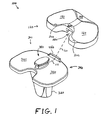
- FIG. 1 shows an exploded perspective view of an exemplary mobile bearing knee prosthesis sub-assembly according to the present invention along an explosion/assembly line;
- FIG. 2 shows a superior plan view of the exemplary tibial implant of the exemplary sub-assembly of FIG. 1 ;
- FIG. 3 shows a medial plan view of the exemplary tibial implant of the exemplary sub-assembly of FIG. 1 ;
- FIG. 4 shows a cross-sectional view of the exemplary tibial implant of the exemplary sub-assembly of FIG. 1 along line 4-4 of FIG. 3 ;
- FIG. 5 shows a cross-sectional view of the exemplary tibial implant of the exemplary sub-assembly of FIG. 1 along line 5-5 of FIG. 2 ;
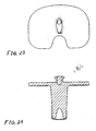
- FIG. 6 shows a superior plan view of the exemplary tibio-femoral insert of the exemplary sub-assembly of FIG. 1 ;
- FIG. 7 shows a lateral plan view of the exemplary tibio-femoral insert of the exemplary sub-assembly of FIG. 1 ;
- FIG. 8 shows an inferior plan view of the exemplary tibio-femoral insert of the exemplary sub-assembly of FIG. 1 ;
- FIG. 9 shows a cross-sectional view of the exemplary tibio-femoral insert of the exemplary sub-assembly of FIG. 1 along line 9-9 of FIG. 6 ;
- FIG. 10 shows a cross-sectional view of the exemplary tibio-femoral insert of the exemplary sub-assembly of FIG. 1 along line 10-10 of FIG. 6 ;
- FIG. 11 shows an assembled perspective view of the exemplary sub-assembly of FIG. 1 ;
- FIG. 12 shows a cross-sectional view of the exemplary sub-assembly of FIG. 1 along line 12-12 of FIG. 11 ;
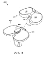
- FIG. 13 shows an exploded perspective view of an exemplary alternative mobile bearing knee prosthesis sub-assembly according to the present invention along an explosion/assembly line;
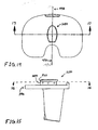
- FIG. 14 shows a superior plan view of the exemplary tibial implant of the exemplary sub-assembly of FIG. 13 ;
- FIG. 15 shows a medial plan view of the exemplary tibial implant of the exemplary sub-assembly of FIG. 13 ;
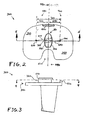
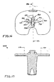
- FIG. 16 shows a cross-sectional view of the exemplary tibial implant of the exemplary sub-assembly of FIG. 13 along line 16-16 of FIG. 15 ;
- FIG. 17 shows a cross-sectional view of the exemplary tibial implant of the exemplary sub-assembly of FIG. 13 along line 17-17 of FIG. 14 ;
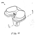
- FIG. 18 shows an assembled perspective view of the exemplary sub-assembly of FIG. 13 ;
- FIG. 19 shows a cross-sectional view of the exemplary sub-assembly of FIG. 13 along line 19-19 of FIG. 18 ;
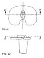
- FIGs. 20-30 show views of another exemplary alternative mobile bearing knee prosthesis sub-assembly according to the present invention.
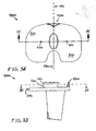
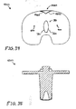
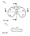
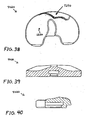
- FIGs. 31-42 show views of another exemplary alternative mobile bearing knee prosthesis sub-assembly according to the present invention.
- the terms “medial,” “medially,” and the like mean pertaining to the middle, in or toward the middle, and/or nearer to the middle of the body when standing upright.
- the terms “lateral,” “laterally,” and the like are used herein as opposed to medial.
- the medial side of the knee is the side closest to the other knee and the closest sides of the knees are medially facing, whereas the lateral side of the knee is the outside of the knee and is laterally facing.
- the term “superior” means closer to the top of the head and/or farther from the bottom of the feet when standing upright.
- the term “inferior” is used herein as opposed to superior.
- the heart is superior to the stomach and the superior surface of the tongue rests against the palate, whereas the stomach is inferior to the heart and the palate faces inferiorly toward the tongue.
- the terms “anterior,” “anteriorly,” and the like mean nearer the front or facing away from the front of the body when standing upright, as opposed to “posterior,” “posteriorly,” and the like, which mean nearer the back or facing away from the back of the body.
- FIG. 1 shows an exploded perspective view of an exemplary mobile bearing knee prosthesis sub-assembly 100 according to the present invention along an explosion/assembly line 110.
- Sub-assembly 100 includes an exemplary tibio-femoral insert 120.
- insert 120 is configured to emulate a natural tibial plateau (not shown) and natural meniscus (not shown) for a left knee replacement.
- insert 120 is made from Ultra High Molecular Weight Polyethylene ("UHMWPE").
- UHMWPE Ultra High Molecular Weight Polyethylene
- insert 120 may be made from any other suitably strong, smooth, low-wearing biocompatible material(s).
- Insert 120 includes a generally anteriorly positioned generally concave superior surface 140 configured to minimize the possibility of impingement of the natural or prosthetic patella (not shown) and the patellar tendon. Insert 120 also includes a generally medially positioned generally concave superior surface 160 and a generally laterally positioned generally concave superior surface 180 which are configured to bear against a generally symmetrical femoral implant (not shown). In the exemplary embodiment, surface 160 and surface 180 have about the same curvature(s). In alternative embodiments, surface 160 and surface 180 may differ in curvature to accommodate a generally asymmetrical femoral implant (not shown).
- Insert 120 also includes a generally posteriorly positioned chamfered superior surface 200 configured to minimize soft tissue impingement of a posterior cruciate ligament (not shown). Further, insert 120 defines a generally centrally positioned arcuate cavity or slot 220 that is partially discernable in FIG. 1 . Slot 220 is discussed further below.
- Sub-assembly 100 further includes an exemplary tibial implant 300.
- implant 300 is configured to anchor into a proximal tibia (not shown) and to support and align insert 120.
- Implant 300 is medially-laterally symmetrical such that it can be used effectively in either a right or left knee.
- implant 300 is made from a cobalt chrome alloy.
- implant 300 may be made from a titanium alloy or any other suitable biocompatible material(s).
- Implant 300 includes a stem 320 configured to anchor into the metaphysic and/or intramedullary canal (not shown) of the proximal tibia (not shown).
- Implant 300 also includes a tibial plate 340 configured to support and align insert 120.
- Plate 340 includes a substantially flat highly polished or otherwise suitably smooth superior surface 360.
- Implant 300 also includes a generally centrally positioned stud-like protuberance 380 extending generally superiorly from plate 340.
- protuberance 380 is configured to cooperate with slot 220 such that insert 120 is moveable relative to plate 340 about a medially-offset axis 400 (see FIG. 2 , FIG. 4, and FIG. 5 ).
- Implant 300 also includes a generally anteriorly positioned bar-like protuberance 420 extending generally superiorly from plate 340.
- protuberance 420 is configured to cooperate with insert 120 to limit the motion of insert 120 relative to plate 340 as discussed further below.
- FIG. 2 shows a superior plan view of implant 300.
- plate 340 includes a medial lobe 460 and a lateral lobe 480 conjoined in a dividing plane 490; surface 360 extends over lobe 460 and lobe 480; lobe 460 and lobe 480 together define a generally posteriorly positioned generally U-shaped space 500; and plane 490 medially-laterally bisects protuberance 380, protuberance 420, and space 500.
- protuberance 380 includes a protuberance sidewall 520 (see FIG. 3 ) extending from plate 340 and a boss 540 (see FIG. 3 ) topping off or capping sidewall 520.
- Boss 540 (see FIG. 3 ) includes a medial convex arcuate portion 560 and an opposing lateral convex arcuate portion 580 conjoined in plane 490. Portion 560 is eccentric to portion 580, and boss 540 (see FIG. 3 ) is greater in span anteriorly-posteriorly than it is medially-laterally such that boss 540 (see FIG. 3 ) is generally ovularly cross-sectionally shaped.
- portion 560 has a curvature radius 600 relative to a laterally-offset axis 620; portion 580 has a curvature radius 640 relative to axis 400; axis 400 is medially disposed from plane 490 by a distance 680; axis 620 is laterally disposed from plane 490 by a distance 700; axis 400 is disposed from axis 620 by a distance 720 that orthogonally passes through plane 490; axis 400 and axis 620 are roughly equidistant from plane 490; radius 600 is roughly equal in magnitude to radius 640; distance 680 is roughly equal in magnitude to distance 700; and portion 560 and portion 580 define a medial-lateral span 740 roughly equaling the scalar sum of radius 600 and radius 640 minus distance 720.
- FIG. 3 shows a medial plan view of implant 300.
- Plate 340, protuberance 420, sidewall 520, and boss 540, among other things, are at least partially discernable in FIG. 3 .
- FIG. 4 shows a cross-sectional view of implant 300 along line 4-4 of FIG. 3 .
- plane 490 medially-laterally bisects sidewall 520; and sidewall 520 includes a medial convex arcuate portion 760 and an opposing lateral convex arcuate portion 780 conjoined in plane 490.
- Portion 760 is eccentric to portion 780, and sidewall 520 is greater in span anteriorly-posteriorly than it is medially-laterally such that sidewall 520 is generally ovularly cross-sectionally shaped.
- portion 760 has a curvature radius 800 relative to axis 620; portion 780 has a curvature radius 840 relative to axis 400; radius 800 is roughly equal in magnitude to radius 840; and portion 760 and portion 780 define a medial-lateral span 920 roughly equaling the scalar sum of radius 800 and radius 840 minus distance 720.
- radius 800 is somewhat smaller than radius 600 (see FIG. 2 ) and radius 840 is likewise smaller than radius 640 (see FIG. 2 ) such that span 740 (see FIG. 2 ) is somewhat greater than span 920 (see also FIG. 5 ).
- Surface 360, protuberance 420, distance 680, and distance 700 are also at least partially discernable in FIG. 4 .
- FIG. 5 shows a cross-sectional view of implant 300 along line 5-5 of FIG. 2 .
- Axis 400, protuberance 420, plane 490, axis 620, distance 680, distance 700, distance 720, distance 740, and distance 920, among other things, are at least partially discernable in FIG. 5 .
- FIG. 6 shows a superior plan view of insert 120.
- insert 120 includes a medial lobe 1000 and a lateral lobe 1020 conjoined in a dividing plane 1040.
- Lobe 1000 and lobe 1020 together define a generally posteriorly positioned generally U-shaped space 1030 bisected by plane 1040.
- Lobe 1000 has anterior-posterior span 1060, while lobe 1020 has anterior-posterior span 1080 that is somewhat smaller than span 1060.
- anterior-posterior asymmetry may be desirable to enhance modeling of a natural knee (not shown) and/or to otherwise enhance loading/wear characteristics of sub-assembly 100, and/or to reduce the possibility of impingement of the surrounding soft tissues of the knee.
- span 1060 and span 1080 may be roughly equal in alternative embodiments.
- Lobe Surface 140, surface 160, surface 180, and surface 200, among other things, are at least partially discernable in FIG. 6 .
- FIG. 7 shows a lateral plan view of insert 120.
- insert 120 includes a substantially flat smooth inferior surface 1100 and surface 200 is chamfered at an angle 1120 relative to surface 1100.
- angle 1120 is at least 30 degrees and not more than 65 degrees.
- lobe 1020 (see FIG. 6 ) of insert 120 also includes a generally posteriorly positioned chamfered inferior surface 1140 configured to facilitate generally anterior-to-posterior insertion of insert 120 to implant 300 in a minimally invasive operating space (not shown) along line 110 (see FIG. 1 ).
- Surface 1140 is chamfered at an angle 1160 relative to surface 1100.
- lobe 1000 see FIG.
- FIG. 6 also includes a generally posteriorly positioned chamfered inferior surface 1180 (see FIG. 8 ) configured to facilitate generally anterior-to-posterior insertion of insert 120 to implant 300 in a minimally invasive operating space (not shown) along line 110 (see FIG. 1 ).
- Surface 1180 is also chamfered at angle 1160 relative to surface 1100.
- FIG. 8 shows an inferior plan view of insert 120.
- slot 220 opens generally posteriorly and generally inferiorly and extends generally longitudinally into insert 120 with a central or mean curvature radius 1200 relative to an axis 1220.
- slot 220 is configured to receive and slidably engage protuberance 380 (see FIG. 1 ) such that insert 120 is moveable relative to plate 340 about axis 400 (see FIG. 2 , FIG. 4, and FIG. 5 ) and slot 220 is further configured to inferiorly-superiorly retain boss 540 (see FIG. 3 ) such that insert 120 is inferiorly-superiorly retained on plate 340.
- slot 220 is arcuately sized to allow about 10-25 degrees of external rotation of insert 120 relative to plate 340 about axis 400.
- the exemplary embodiment axis 1220 is medially disposed from plane 1040 by a distance 1240, and radius 1200 is roughly equal in magnitude to distance 1240.
- Distance 1240 is roughly equal in magnitude to distance 680 (see FIG. 4 and FIG. 5 ).
- slot 220 has a generally medial-side curvature radius 1260 relative to axis 1220 and a generally lateral-side curvature radius 1280 relative to axis 1220.
- Radius 1260 is roughly equal in magnitude to distance 720 minus the magnitude of radius 840.
- Radius 1280 is roughly equal in magnitude to the magnitude of radius 840 (see FIG. 4 and FIG. 8 ).
- Slot 220 also includes a roughly innermost portion or apex portion 1290.
- insert 120 also defines a recess 1300 bounded superiorly by a substantially planar smooth ceiling surface 1320 and bounded generally posteriorly and laterally by a wall 1340 that extends generally inferiorly from surface 1320 to surface 1100.
- wall 1340 is configured to prevent any more than about 10-25 degrees of internal rotation of insert 120 relative to plate 340 (see FIG. 1 ) by abutting against protuberance 420 (see FIG. 1 ) when the internal rotational limit is reached.
- Space 1030, surface 1140 and surface 1180 are also at least partially discernable in FIG. 8 .
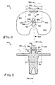
- FIG. 9 shows a cross-sectional view of insert 120 along line 9-9 of FIG. 6 .
- slot 220 includes a tapered portion 1400 opening at surface 1100, extending generally superiorly from surface 1100, and arcing generally posteriorly-anteriorly inward.
- slot 220 includes a neck portion 1420 extending generally superiorly from portion 1400 and arcing generally posteriorly-anteriorly inward.
- Portion 1420 is configured to slidably engage portion 520 of protuberance 380 (see FIG. 3 ).
- Slot 220 also includes a head portion 1440 extending generally superiorly from portion 1420 and arcing generally posteriorly-anteriorly inward.
- Portion 1440 is configured to inferior-superiorly retain boss 540 (see FIG. 3 ) without significantly interfering with the slidable engagement between portion 1420 of slot 220 and portion 520 of protuberance 380.
- Surface 160 and surface 180 are also at least partially discernable in FIG. 9 .
- FIG. 10 shows a cross-sectional view of insert 120 along line 10-10 of FIG. 6 .
- Surface 200, surface 1140, portion 1400, portion 1420, and portion 1440, among other things, are at least partially discernable in FIG. 10 .
- FIG. 11 shows an assembled perspective view of sub-assembly 100.
- Insert 120 including surface 160 and surface 180
- implant 300 including stem 320, plate 340, and surface 360 of plate 340
- FIG. 11 shows an assembled perspective view of sub-assembly 100.
- Insert 120 including surface 160 and surface 180
- implant 300 including stem 320, plate 340, and surface 360 of plate 340
- FIG. 11 shows an assembled perspective view of sub-assembly 100.
- Insert 120 including surface 160 and surface 180
- implant 300 including stem 320, plate 340, and surface 360 of plate 340
- insert 120 1 the superior positioning of insert 120 and the sloping of line 110 are exaggerated for clarity of exposition.
- the user progressively slides slot 220 over protuberance 380 (moving insert 120 generally anteriorly to posteriorly into the joint space) until protuberance 420 clears wall 1340 such that insert 120 snaps into final engagement with tibial plate 340.
- this low-profile, generally anterior to posterior assembly is well suited for minimally invasive surgeries.
- the user attaches a suitable femoral implant to the distal femur and closes the surgical site as known.
- An alternate embodiment of the disclosed invention includes a removable anterior protuberance to facilitate insertion of tibio-femoral insert 120 to implant 300.
- FIG. 12 shows a cross-sectional view of sub-assembly 100 along line 12-12 of FIG. 11 .
- axis 1220 insert 120
- axis 400 implant 300
- surface 360 implant 300; see FIG. 1
- slidably supports surface 1100 insert 120
- the slidable engagement between protuberance 380 (implant 300) and slot 220 (insert 120) provides freedom of motion (more particularly, external rotational freedom) for insert 120 relative to plate 340 about axis 400 (and axis 1220) as generally indicated by directional line 1460.
- the external rotational freedom is limited to about 10-25 degrees when protuberance 380 abuts portion 1290 of slot 220.
- the engagement between protuberance 380 and slot 220 also provides internal rotational freedom for insert 120 relative to plate 340 about axis 400 (and axis 1220) as generally indicated by directional line 1480.
- the internal rotational freedom is not limited by protuberance 380 or slot 220.
- the internal rotational freedom of insert 120 relative to plate 340 is limited to about 10-25 degrees when protuberance 420 abuts wall 1340. Further, it is noted that the elongated arcuate engagement between portion 780 (protuberance 380; see FIG.
- Portion 560, portion 760, and surface 1320 are at least partially discernable in FIG. 12 .
- FIG. 13 shows an exploded perspective view of an exemplary alternative mobile bearing knee prosthesis sub-assembly 1400 according to the present invention along an explosion/assembly line 1410.
- Sub-assembly 1400 includes insert 120 (discussed above) and an alternative tibial implant 1600.
- Implant 1600 is identical to implant 300 (discussed above) with the exception that protuberance 380 is replaced with an alternative generally centrally positioned stud-like protuberance 1680 extending generally superiorly from plate 340.
- FIG. 14 shows a superior plan view of implant 1600. As discernable in FIG. 14 , plane 490 medially-laterally bisects protuberance 1680.
- FIG. 15 shows a medial plan view of implant 1600.
- Protuberance 1680 is identical to protuberance 380 with the exception that protuberance sidewall 520 is replaced with an alternative protuberance sidewall 1820 extending from plate 340 to boss 540.
- FIG. 16 shows a cross-sectional view of implant 1600 along line 16-16 of FIG. 15 .
- plane 490 medially-laterally bisects sidewall 1820; and sidewall 1820 includes a generally anteriorly positioned pair of opposing convex arcuate portions 1880, a generally centrally positioned pair of opposing concave arcuate portions 1900, and a generally posteriorly positioned pair of opposing convex arcuate portions 1920.
- Portions 1880 have opposing curvature radii 1940 relative to axis 400 and axis 620, respectively (for clarity of depiction, only the radius relative to axis 400 is shown). Radii 1940 are equal in magnitude to radius 800 (discussed above).
- Portions 1900 have opposing curvature radii 1960 and 1980 relative to axis 400 and axis 620, respectively. Radii 1960 and 1980 are equal in magnitude to radius 1260 (discussed above). Portions 1920 have opposing curvature radii 2000 relative to axis 400 and axis 620, respectively (for clarity of depiction, only the radius relative to axis 620 is shown). Radii 2000 are equal in magnitude to radius 800 (discussed above). Consequently, it should be appreciated that in the exemplary embodiment protuberance 1680 is generally hour-glass cross-sectionally shaped.
- FIG. 17 shows a cross-sectional view of implant 1600 along line 17-17 of FIG. 14 .
- Axis 400 and axis 620 are at least partially discernable in FIG. 17 .
- FIG. 18 shows an assembled perspective view of sub-assembly 1400; and FIG. 19 shows a cross-sectional view of sub-assembly 1400 along line 19-19 of FIG. 18 .
- Assembly and operation of sub-assembly 1400 should be readily appreciable from the drawings and from reference to the assembly and operation of sub-assembly 100 (discussed above).
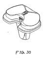
- FIGs. 20-30 show views of another exemplary alternative mobile bearing knee prosthesis sub-assembly 3000 according to the present invention.
- Sub-assembly 3000 is made and used in a like manner to sub-assembly 100 with the notable exceptions that protuberance 420 (see FIG. 1 ) and wall 1340 (see FIG. 8 ) are omitted, and internal/external rotational stop features are provided by a generally centrally positioned peg 3020 or, alternatively, a screw extending generally superiorly from an alternative tibial implant 3040 in cooperation with an arcuate inferiorly and posteriorly open channel 3060 into which peg 3020 protrudes. Assembly and operation of sub-assembly 3000 should be readily appreciable from the drawings and from reference to the assembly and operation of sub-assembly 100 (discussed above).
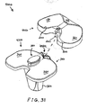
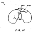
- FIGs. 31-42 show views of another exemplary alternative mobile bearing knee prosthesis sub-assembly 4000 according to the present invention.
- Sub-assembly 4000 is made and used in a like manner to sub-assembly 100 with the notable exceptions that internal/external rotational stop features are provided by cooperation between an alternative bi-arcuate protuberance 4420 (see FIG. 31 ) and an alternative wall 5340 (see FIG. 38 ) that replace protuberance 420 (see FIG. 1 ) and wall 1340 (see FIG. 8 ), respectively.
- protuberance 4420 includes a generally medially positioned arcuate surface 4440 that is concentric to portion 780 of protuberance 340, and includes a generally laterally positioned arcuate surface 4460 that is concentric to portion 760 of protuberance 380 (see FIG. 34 ). Assembly and operation of sub-assembly 4000 should be readily appreciable from the drawings and from reference to the assembly and operation of sub-assembly 100 (discussed above).
Landscapes
- Health & Medical Sciences (AREA)
- Orthopedic Medicine & Surgery (AREA)
- Physical Education & Sports Medicine (AREA)
- Cardiology (AREA)
- Oral & Maxillofacial Surgery (AREA)
- Transplantation (AREA)
- Engineering & Computer Science (AREA)
- Biomedical Technology (AREA)
- Heart & Thoracic Surgery (AREA)
- Vascular Medicine (AREA)
- Life Sciences & Earth Sciences (AREA)
- Animal Behavior & Ethology (AREA)
- General Health & Medical Sciences (AREA)
- Public Health (AREA)
- Veterinary Medicine (AREA)
- Prostheses (AREA)
Claims (15)
- Appareil formant prothèse de genou avec palier mobile, comprenant :une plaque tibiale (340) incluant un lobe médial et un lobe latéral réunis dans un plan de division ;un insert tibial-fémoral (120) ; etune protubérance semblable à un téton (380) s'étendant depuis la plaque tibiale (340) jusque dans l'insert tibial-fémoral, la protubérance semblable à un téton (380) incluant une paroi latérale de protubérance (520) positionnée dans l'insert tibial-fémoral (120), la paroi latérale de protubérance (520) étant recoupée en deux par le plan de division (490) et incluant une paire de portions arquées convexes excentriques (760, 780) opposées,dans lequel la paire de portions arquées convexes excentriques (760, 780) opposées incluent une première portion arquée convexe (780) ayant un rayon de courbure (840) et un centre de courbure qui est placé sur un axe disposé de manière médiane (400), la paire de portions arquées convexes excentriques (780, 760) opposées inclut en outre une seconde portion arquée convexe (760) ayant un rayon de courbure et un centre de courbure qui est placé sur un axe (620) disposé latéralement depuis le plan de division (490), et le rayon de courbure (840) de la première portion arquée convexe (780) a en gros une longueur égale au rayon de courbure (800) de la seconde portion arquée convexe (760) ;dans lequel l'insert tibial-fémoral (120) est déplaçable par rapport à la plaque tibiale (340) autour dudit axe (400) disposé de façon médiane depuis le plan de division ; etdans lequel l'insert tibial-fémoral définit une fente (220) et la paroi latérale de protubérance (520) est positionnée dans la fente (220) ;caractérisé en ce queladite fente (220) possède un rayon de courbure (1280) généralement du côté latéral en gros égal au rayon de courbure (840) de la première portion arquée convexe (780) de la paroi latérale de protubérance (520).
- Appareil selon la revendication 1, dans lequel l'axe disposé de façon médiane (400) est disposé à une première distance (400) depuis le plan de division (490, 1040), et la fente (220) possède un rayon de courbure moyen (1200) en gros égal en longueur à la première distance (700).
- Appareil selon la revendication 2, dans lequel la fente (220) possède un rayon de courbure, généralement du côté médian (1260), en gros égal à une distance (720) entre l'axe (620) disposé latéralement et l'axe (400) disposé de façon médiane, diminué du rayon de courbure (840) de la première portion arquée convexe (780) de la paroi latérale de protubérance (520).
- Appareil selon la revendication 3, dans lequel la paroi latérale de protubérance (520) présente généralement une forme de section transversale ovale.
- Appareil selon la revendication 1, dans lequel la paroi latérale de protubérance (520) inclut encore une paire de portions arquées concaves excentriques (1900) opposées, la paire de portions arquées concaves excentriques (1900) opposées incluent une première portion arquée concave (1900) ayant un rayon de courbure (1960) et un centre de courbure qui est placé sur l'axe disposé de façon médiane (400), la paire de portions arquées concaves excentriques (1900) opposées incluent en outre une seconde portion arquée convexe (1900) ayant un rayon de courbure (1980) et un centre de courbure qui est placé sur l'axe disposé latéralement (620), et le rayon de courbure (1960) de la première portion arquée concave (1900) est en gros égal en longueur au rayon de courbure (1980) de la seconde portion arquée concave (1900).
- Appareil selon la revendication 5, dans lequel l'axe disposé de façon médiane (400) est disposé à une première distance (680) depuis le plan de division (490), et la fente (220) possède un rayon de courbure moyen (1200) en gros égal en longueur à la première distance (680).
- Appareil selon la revendication 6, dans lequel la fente (220) possède un rayon de courbure (1260), généralement du côté médian, en gros égal à une distance (720) entre l'axe disposé latéralement (620) et l'axe disposé de façon médiane (400), diminué du rayon de courbure (840) de la première portion arquée convexe (780) de la paroi latérale de protubérance (520).
- Appareil selon la revendication 7, dans lequel la paroi latérale de protubérance (520) a une forme de section transversale généralement en forme de sablier.
- Appareil selon la revendication 1, comprenant en outre :une protubérance semblable à une barre (420, 4420) s'étendant depuis la plaque tibiale (340) ;dans lequel l'insert tibial-fémoral (120) définit un évidement (1300, 5340) et la protubérance semblable à une barre (420) est positionnée dans l'évidement (1300, 5340).
- Appareil selon la revendication 9, dans lequel la protubérance semblable à une barre (420, 4420) est amovible depuis le plateau tibial (340).
- Appareil selon la revendication 9, dans lequel la protubérance semblable à une barre (420, 4420) est recoupée par le plan de division (490, 1040) et inclut une pluralité de surfaces arquées (4440, 4460).
- Appareil selon la revendication 1, comprenant en outre :une protubérance semblable à une barre (4420) s'étendant depuis la plaque tibiale (340) ;dans lequel la protubérance semblable à une barre (4420) inclut une surface arquée (4440) positionnée de façon généralement médiane et concentrique à la première portion arquée convexe (780) de la paroi latérale de protubérance (520), la protubérance semblable à une barre (4420) inclut en outre une surface arquée (4460) positionnée de façon généralement latérale et concentrique à la seconde portion arquée convexe (760) de la paroi latérale de protubérance (520), l'insert tibial-fémoral (120) définit un évidement (5340), et la protubérance semblable à une barre (4420) est positionnée dans l'évidement (5340).
- Appareil selon la revendication 1, comprenant en outre :des moyens, intégrés avec un élément au moins parmi la plaque tibiale (340) et l'insert tibial-fémoral (120), pour limiter le mouvement de l'insert tibial-fémoral (120) par rapport à la plaque tibiale (340).
- Appareil selon la revendication 1, dans lequel l'insert tibial-fémoral (120) inclut une surface supérieure chanfreinée (200) positionnée généralement postérieurement et définit un espace généralement en forme de U positionné généralement postérieurement, bordé au moins en partie par la surface chanfreinée (200).
- Appareil selon la revendication 14, dans lequel la surface chanfreinée (200) est chanfreinée à un angle entre 30° et 65°, inclus.
Applications Claiming Priority (2)
| Application Number | Priority Date | Filing Date | Title |
|---|---|---|---|
| US55210404P | 2004-03-09 | 2004-03-09 | |
| US552104P | 2004-03-09 |
Publications (3)
| Publication Number | Publication Date |
|---|---|
| EP1574185A2 EP1574185A2 (fr) | 2005-09-14 |
| EP1574185A3 EP1574185A3 (fr) | 2005-11-16 |
| EP1574185B1 true EP1574185B1 (fr) | 2012-05-23 |
Family
ID=34826266
Family Applications (1)
| Application Number | Title | Priority Date | Filing Date |
|---|---|---|---|
| EP05005021A Not-in-force EP1574185B1 (fr) | 2004-03-09 | 2005-03-08 | Composant tibial de genou avec un roulement mobile |
Country Status (2)
| Country | Link |
|---|---|
| US (1) | US8137407B2 (fr) |
| EP (1) | EP1574185B1 (fr) |
Families Citing this family (119)
| Publication number | Priority date | Publication date | Assignee | Title |
|---|---|---|---|---|
| US6558426B1 (en) | 2000-11-28 | 2003-05-06 | Medidea, Llc | Multiple-cam, posterior-stabilized knee prosthesis |
| US8388624B2 (en) | 2003-02-24 | 2013-03-05 | Arthrosurface Incorporated | Trochlear resurfacing system and method |
| US7749250B2 (en) | 2006-02-03 | 2010-07-06 | Biomet Sports Medicine, Llc | Soft tissue repair assembly and associated method |
| US7909851B2 (en) | 2006-02-03 | 2011-03-22 | Biomet Sports Medicine, Llc | Soft tissue repair device and associated methods |
| US8303604B2 (en) | 2004-11-05 | 2012-11-06 | Biomet Sports Medicine, Llc | Soft tissue repair device and method |
| US8118836B2 (en) | 2004-11-05 | 2012-02-21 | Biomet Sports Medicine, Llc | Method and apparatus for coupling soft tissue to a bone |
| US8128658B2 (en) | 2004-11-05 | 2012-03-06 | Biomet Sports Medicine, Llc | Method and apparatus for coupling soft tissue to bone |
| US8298262B2 (en) | 2006-02-03 | 2012-10-30 | Biomet Sports Medicine, Llc | Method for tissue fixation |
| US8361113B2 (en) | 2006-02-03 | 2013-01-29 | Biomet Sports Medicine, Llc | Method and apparatus for coupling soft tissue to a bone |
| US7601165B2 (en) | 2006-09-29 | 2009-10-13 | Biomet Sports Medicine, Llc | Method and apparatus for forming a self-locking adjustable suture loop |
| US8088130B2 (en) | 2006-02-03 | 2012-01-03 | Biomet Sports Medicine, Llc | Method and apparatus for coupling soft tissue to a bone |
| US9017381B2 (en) | 2007-04-10 | 2015-04-28 | Biomet Sports Medicine, Llc | Adjustable knotless loops |
| US8137382B2 (en) | 2004-11-05 | 2012-03-20 | Biomet Sports Medicine, Llc | Method and apparatus for coupling anatomical features |
| US7905904B2 (en) | 2006-02-03 | 2011-03-15 | Biomet Sports Medicine, Llc | Soft tissue repair device and associated methods |
| US7695519B2 (en) * | 2005-07-08 | 2010-04-13 | Howmedica Osteonics Corp. | Modular tibial baseplate |
| US10517587B2 (en) | 2006-02-03 | 2019-12-31 | Biomet Sports Medicine, Llc | Method and apparatus for forming a self-locking adjustable loop |
| US11259792B2 (en) | 2006-02-03 | 2022-03-01 | Biomet Sports Medicine, Llc | Method and apparatus for coupling anatomical features |
| US8597327B2 (en) | 2006-02-03 | 2013-12-03 | Biomet Manufacturing, Llc | Method and apparatus for sternal closure |
| US8562645B2 (en) | 2006-09-29 | 2013-10-22 | Biomet Sports Medicine, Llc | Method and apparatus for forming a self-locking adjustable loop |
| US8652171B2 (en) | 2006-02-03 | 2014-02-18 | Biomet Sports Medicine, Llc | Method and apparatus for soft tissue fixation |
| US9468433B2 (en) | 2006-02-03 | 2016-10-18 | Biomet Sports Medicine, Llc | Method and apparatus for forming a self-locking adjustable loop |
| US8968364B2 (en) | 2006-02-03 | 2015-03-03 | Biomet Sports Medicine, Llc | Method and apparatus for fixation of an ACL graft |
| US11311287B2 (en) | 2006-02-03 | 2022-04-26 | Biomet Sports Medicine, Llc | Method for tissue fixation |
| US8562647B2 (en) | 2006-09-29 | 2013-10-22 | Biomet Sports Medicine, Llc | Method and apparatus for securing soft tissue to bone |
| US9078644B2 (en) | 2006-09-29 | 2015-07-14 | Biomet Sports Medicine, Llc | Fracture fixation device |
| US8801783B2 (en) | 2006-09-29 | 2014-08-12 | Biomet Sports Medicine, Llc | Prosthetic ligament system for knee joint |
| US7771484B2 (en) * | 2006-02-28 | 2010-08-10 | Howmedica Osteonics Corp. | Modular tibial implant |
| WO2007108804A1 (fr) * | 2006-03-21 | 2007-09-27 | Komistek Richard D | Prothèses d'arthroplastie totale à moments induits |
| US8672969B2 (en) | 2006-09-29 | 2014-03-18 | Biomet Sports Medicine, Llc | Fracture fixation device |
| US11259794B2 (en) | 2006-09-29 | 2022-03-01 | Biomet Sports Medicine, Llc | Method for implanting soft tissue |
| US7947082B2 (en) * | 2006-11-09 | 2011-05-24 | Consensus Orthopedics, Inc. | System and method for joint arthroplasty |
| AU2007332787A1 (en) | 2006-12-11 | 2008-06-19 | Arthrosurface Incorporated | Retrograde resection apparatus and method |
| US12502169B2 (en) | 2007-01-16 | 2025-12-23 | Biomet Sports Medicine, Llc | Soft tissue repair device and associated methods |
| US8715359B2 (en) | 2009-10-30 | 2014-05-06 | Depuy (Ireland) | Prosthesis for cemented fixation and method for making the prosthesis |
| US7628818B2 (en) * | 2007-09-28 | 2009-12-08 | Depuy Products, Inc. | Fixed-bearing knee prosthesis having interchangeable components |
| US8470047B2 (en) * | 2007-09-25 | 2013-06-25 | Depuy (Ireland) | Fixed-bearing knee prosthesis |
| US20110035017A1 (en) * | 2007-09-25 | 2011-02-10 | Depuy Products, Inc. | Prosthesis with cut-off pegs and surgical method |
| US8632600B2 (en) | 2007-09-25 | 2014-01-21 | Depuy (Ireland) | Prosthesis with modular extensions |
| US8128703B2 (en) * | 2007-09-28 | 2012-03-06 | Depuy Products, Inc. | Fixed-bearing knee prosthesis having interchangeable components |
| US20090088861A1 (en) * | 2007-09-27 | 2009-04-02 | Finsbury (Development) Limited | Prosthesis |
| US9204967B2 (en) * | 2007-09-28 | 2015-12-08 | Depuy (Ireland) | Fixed-bearing knee prosthesis having interchangeable components |
| US8206451B2 (en) | 2008-06-30 | 2012-06-26 | Depuy Products, Inc. | Posterior stabilized orthopaedic prosthesis |
| US8187335B2 (en) | 2008-06-30 | 2012-05-29 | Depuy Products, Inc. | Posterior stabilized orthopaedic knee prosthesis having controlled condylar curvature |
| US8192498B2 (en) | 2008-06-30 | 2012-06-05 | Depuy Products, Inc. | Posterior cructiate-retaining orthopaedic knee prosthesis having controlled condylar curvature |
| US9168145B2 (en) | 2008-06-30 | 2015-10-27 | Depuy (Ireland) | Posterior stabilized orthopaedic knee prosthesis having controlled condylar curvature |
| US9119723B2 (en) | 2008-06-30 | 2015-09-01 | Depuy (Ireland) | Posterior stabilized orthopaedic prosthesis assembly |
| US8828086B2 (en) | 2008-06-30 | 2014-09-09 | Depuy (Ireland) | Orthopaedic femoral component having controlled condylar curvature |
| US8236061B2 (en) | 2008-06-30 | 2012-08-07 | Depuy Products, Inc. | Orthopaedic knee prosthesis having controlled condylar curvature |
| US12245759B2 (en) | 2008-08-22 | 2025-03-11 | Biomet Sports Medicine, Llc | Method and apparatus for coupling soft tissue to bone |
| US12419632B2 (en) | 2008-08-22 | 2025-09-23 | Biomet Sports Medicine, Llc | Method and apparatus for coupling anatomical features |
| US20110213467A1 (en) * | 2009-01-20 | 2011-09-01 | Zimmer, Inc. | Orthopaedic implant with woven ingrowth material |
| US8100932B2 (en) | 2009-03-31 | 2012-01-24 | Onciomed, Inc. | Method and apparatus for treating obesity and controlling weight gain using self-expanding intragastric devices |
| WO2010121250A1 (fr) | 2009-04-17 | 2010-10-21 | Arthrosurface Incorporated | Système et procédé de re-surfaçage de glénoïde |
| US10945743B2 (en) | 2009-04-17 | 2021-03-16 | Arthrosurface Incorporated | Glenoid repair system and methods of use thereof |
| US8915965B2 (en) | 2009-05-07 | 2014-12-23 | Depuy (Ireland) | Anterior stabilized knee implant |
| US8343227B2 (en) | 2009-05-28 | 2013-01-01 | Biomet Manufacturing Corp. | Knee prosthesis assembly with ligament link |
| US8894715B2 (en) | 2009-05-28 | 2014-11-25 | Biomet Manufacturing, Llc | Knee prosthesis |
| US12096928B2 (en) | 2009-05-29 | 2024-09-24 | Biomet Sports Medicine, Llc | Method and apparatus for coupling soft tissue to a bone |
| US12551209B2 (en) | 2009-06-22 | 2026-02-17 | Biomet Sports Medicine, Llc | Method and apparatus for coupling soft tissue to a bone |
| US9095453B2 (en) * | 2009-08-11 | 2015-08-04 | Michael D. Ries | Position adjustable trial systems for prosthetic implants |
| US8906105B2 (en) | 2009-08-11 | 2014-12-09 | Michael D. Ries | Systems and methods for mobile bearing prosthetic knee |
| US8568485B2 (en) * | 2009-08-11 | 2013-10-29 | Imds Corporation | Articulating trials for prosthetic implants |
| US8382848B2 (en) * | 2009-08-11 | 2013-02-26 | Imds Corporation | Position adjustable trial systems for prosthetic implants |
| US8496666B2 (en) | 2009-08-11 | 2013-07-30 | Imds Corporation | Instrumentation for mobile bearing prosthetics |
| US8998997B2 (en) | 2009-08-11 | 2015-04-07 | Michael D. Ries | Implantable mobile bearing prosthetics |
| US8292954B2 (en) | 2009-09-11 | 2012-10-23 | Articulinx, Inc. | Disc-based orthopedic devices |
| US9011547B2 (en) | 2010-01-21 | 2015-04-21 | Depuy (Ireland) | Knee prosthesis system |
| CA2788462C (fr) | 2010-01-29 | 2020-09-01 | Nathaniel M. Lenz | Prothese de genou a preservation des deux ligaments croises |
| CA2792048A1 (fr) | 2010-03-05 | 2011-09-09 | Arthrosurface Incorporated | Systeme et procede de resurfacage tibial |
| WO2012012726A1 (fr) | 2010-07-23 | 2012-01-26 | Medicinelodge, Inc Dba Imds Co-Innovation | Systèmes et procédés pour genou prosthétique |
| US8764840B2 (en) | 2010-07-24 | 2014-07-01 | Zimmer, Inc. | Tibial prosthesis |
| CN103118636B (zh) * | 2010-07-24 | 2016-08-17 | 捷迈有限公司 | 用于膝部假体的非对称胫骨部件 |
| EP2613739B1 (fr) * | 2010-09-10 | 2017-06-07 | Zimmer, Inc. | Composants tibiaux facilitant le mouvement pour une prothèse du genou |
| FR2967346B1 (fr) * | 2010-11-17 | 2012-12-14 | Rodolphe Limozin | Gamme de protheses de genou tricompartimentaires |
| US8603101B2 (en) | 2010-12-17 | 2013-12-10 | Zimmer, Inc. | Provisional tibial prosthesis system |
| US8728167B2 (en) | 2011-01-10 | 2014-05-20 | Howmedica Osteonics Corp. | Bicruciate retaining tibial baseplate design and method of implantation |
| US12329373B2 (en) | 2011-05-02 | 2025-06-17 | Biomet Sports Medicine, Llc | Method and apparatus for soft tissue fixation |
| US9814584B2 (en) | 2011-09-28 | 2017-11-14 | Depuy Ireland Unlimited Company | Fixed-bearing knee prosthesis having a locking mechanism with a concave-to-convex mating interface |
| US8409293B1 (en) * | 2011-10-26 | 2013-04-02 | Sevika Holding AG | Knee prosthesis |
| US9357991B2 (en) | 2011-11-03 | 2016-06-07 | Biomet Sports Medicine, Llc | Method and apparatus for stitching tendons |
| US9381013B2 (en) | 2011-11-10 | 2016-07-05 | Biomet Sports Medicine, Llc | Method for coupling soft tissue to a bone |
| US9357992B2 (en) | 2011-11-10 | 2016-06-07 | Biomet Sports Medicine, Llc | Method for coupling soft tissue to a bone |
| US8690954B2 (en) * | 2011-11-18 | 2014-04-08 | Zimmer, Inc. | Tibial bearing component for a knee prosthesis with improved articular characteristics |
| WO2013077919A1 (fr) | 2011-11-21 | 2013-05-30 | Zimmer, Inc. | Plaque de base tibiale avec placement asymétrique de structures de fixation |
| US9421106B2 (en) | 2011-12-07 | 2016-08-23 | Howmedica Osteonics Corp. | Reverse shoulder baseplate with alignment guide for glenosphere |
| US20130165982A1 (en) | 2011-12-22 | 2013-06-27 | Arthrosurface Incorporated | System and Method for Bone Fixation |
| USD744103S1 (en) | 2011-12-29 | 2015-11-24 | Mako Surgical Corp. | Tibial baseplate |
| USD745158S1 (en) * | 2011-12-29 | 2015-12-08 | Mako Surgical Corp. | Tibial implant components |
| US8911501B2 (en) | 2011-12-29 | 2014-12-16 | Mako Surgical Corp. | Cruciate-retaining tibial prosthesis |
| ES2869958T3 (es) | 2012-01-30 | 2021-10-26 | Zimmer Inc | Componentes tibiales asimétricos para una prótesis de rodilla |
| US8663334B2 (en) * | 2012-05-31 | 2014-03-04 | Howmedica Osteonics Corp. | Lateral entry insert for cup trial |
| US8734523B2 (en) | 2012-05-31 | 2014-05-27 | Howmedica Osteonics Corp. | Limited motion tibial bearing |
| US8906102B2 (en) | 2012-05-31 | 2014-12-09 | Howmedica Osteonics Corp. | Lateral entry insert for cup trial |
| WO2014008126A1 (fr) | 2012-07-03 | 2014-01-09 | Arthrosurface Incorporated | Système et procédé de resurfaçage et de réparation d'articulation |
| EP2882376B1 (fr) * | 2012-08-09 | 2017-06-14 | Peter Stanley Walker | Fonction de substitution d'arthroplastie totale du genou du ligament croisé antérieur |
| FR2994644B1 (fr) * | 2012-08-24 | 2014-08-29 | Anatomic | Embase tibiale prothetique et insert tibial prothetique destine a etre immobilise sur une telle embase tibiale prothetique |
| US9345578B2 (en) | 2013-02-22 | 2016-05-24 | Stryker Corporation | Bicruciate retaining tibial implant system |
| US9918827B2 (en) | 2013-03-14 | 2018-03-20 | Biomet Sports Medicine, Llc | Scaffold for spring ligament repair |
| EP2967885B1 (fr) | 2013-03-15 | 2016-12-14 | Mako Surgical Corporation | Prothèse de genou |
| US9492200B2 (en) | 2013-04-16 | 2016-11-15 | Arthrosurface Incorporated | Suture system and method |
| US9925052B2 (en) | 2013-08-30 | 2018-03-27 | Zimmer, Inc. | Method for optimizing implant designs |
| USD748786S1 (en) * | 2013-10-16 | 2016-02-02 | Depuy (Ireland) | Tibial trial component |
| US20150250472A1 (en) | 2014-03-07 | 2015-09-10 | Arthrosurface Incorporated | Delivery System for Articular Surface Implant |
| US10624748B2 (en) | 2014-03-07 | 2020-04-21 | Arthrosurface Incorporated | System and method for repairing articular surfaces |
| US11607319B2 (en) | 2014-03-07 | 2023-03-21 | Arthrosurface Incorporated | System and method for repairing articular surfaces |
| KR101707592B1 (ko) | 2015-03-05 | 2017-02-17 | 주식회사 코렌텍 | 인공슬관절용 인서트 유닛 |
| EP3352708B1 (fr) | 2015-09-21 | 2020-07-22 | Zimmer, Inc. | Système de prothèse comprenant un élément porteur tibial |
| US10390972B2 (en) | 2016-01-15 | 2019-08-27 | Howmedica Osteonics Corp. | Humeral trial adaptor |
| US10231840B2 (en) | 2016-07-27 | 2019-03-19 | Howmedica Osteonics Corp. | Low profile tibial baseplate with fixation members |
| ES3025978T3 (en) * | 2017-03-10 | 2025-06-10 | Zimmer Inc | Tibial prosthesis with tibial bearing component securing feature |
| AU2018266322B2 (en) | 2017-05-12 | 2020-03-19 | Zimmer, Inc. | Femoral prostheses with upsizing and downsizing capabilities |
| WO2019028344A1 (fr) * | 2017-08-04 | 2019-02-07 | Arthrosurface Incorporated | Implant de surface articulaire à composants multiples |
| US11426282B2 (en) | 2017-11-16 | 2022-08-30 | Zimmer, Inc. | Implants for adding joint inclination to a knee arthroplasty |
| US10898338B1 (en) * | 2018-01-17 | 2021-01-26 | Matthew Budge | Reverse shoulder prosthesis |
| US12121450B2 (en) | 2018-01-17 | 2024-10-22 | Knollwood Orthopedic Innovations Llc | Reverse shoulder prosthesis |
| US10835380B2 (en) | 2018-04-30 | 2020-11-17 | Zimmer, Inc. | Posterior stabilized prosthesis system |
| US11129720B2 (en) * | 2019-03-05 | 2021-09-28 | Jonathan P. GARINO | Cruciate replacing artificial knee |
| GB2609338B (en) | 2019-03-12 | 2023-06-14 | Arthrosurface Inc | Humeral and glenoid articular surface implant systems and methods |
| KR102786625B1 (ko) * | 2023-01-30 | 2025-03-26 | 주식회사 스카이브 | 인공 무릎 관절 삽입물 |
Family Cites Families (53)
| Publication number | Priority date | Publication date | Assignee | Title |
|---|---|---|---|---|
| US4309778A (en) * | 1979-07-02 | 1982-01-12 | Biomedical Engineering Corp. | New Jersey meniscal bearing knee replacement |
| SE450460B (sv) * | 1984-11-28 | 1987-06-29 | Albrektsson Bjoern | Anordning vid konstgjord menisk for en kneledsprotes |
| US4950298A (en) | 1988-04-08 | 1990-08-21 | Gustilo Ramon B | Modular knee joint prosthesis |
| GB8817908D0 (en) * | 1988-07-27 | 1988-09-01 | Howmedica | Tibial component for replacement knee prosthesis |
| US4936853A (en) * | 1989-01-11 | 1990-06-26 | Kirschner Medical Corporation | Modular knee prosthesis |
| US5171276A (en) * | 1990-01-08 | 1992-12-15 | Caspari Richard B | Knee joint prosthesis |
| US5071438A (en) * | 1990-11-07 | 1991-12-10 | Intermedics Orthopedics, Inc. | Tibial prothesis with pivoting articulating surface |
| GB9314839D0 (en) | 1993-07-16 | 1993-09-01 | Walker Peter S | Prosthesis for knee replacement |
| US5609639A (en) * | 1991-02-04 | 1997-03-11 | Walker; Peter S. | Prosthesis for knee replacement |
| US5282868A (en) * | 1991-06-17 | 1994-02-01 | Andre Bahler | Prosthetic arrangement for a complex joint, especially knee joint |
| US5395401A (en) * | 1991-06-17 | 1995-03-07 | Bahler; Andre | Prosthetic device for a complex joint |
| GB9125311D0 (en) * | 1991-11-28 | 1992-01-29 | Biomet Ltd | Prosthetic components |
| NZ243181A (en) * | 1992-04-23 | 1994-10-26 | Michael John Pappas | Prosthetic joint with guide means to limit articulation of a first element and bearing means to two degrees of freedom |
| US6102954A (en) * | 1992-05-18 | 2000-08-15 | Astra Aktiebolag | Joint prosthesis and apparatus for preparing the bone prior to fitting of the prosthesis |
| SE9201557D0 (sv) | 1992-05-18 | 1992-05-18 | Astra Ab | Joint prosthesis and apparatus for preparing the bone prior to fitting of the prosthesis |
| US5412782A (en) * | 1992-07-02 | 1995-05-02 | 3Com Corporation | Programmed I/O ethernet adapter with early interrupts for accelerating data transfer |
| DE9212879U1 (de) * | 1992-09-24 | 1994-01-27 | Waldemar Link GmbH & Co, 22339 Hamburg | Kniegelenkendoprothese zum Ersatz der Schienbein-Gelenkflächen |
| US5658342A (en) * | 1992-11-16 | 1997-08-19 | Arch Development | Stabilized prosthetic knee |
| US5413604A (en) * | 1992-12-24 | 1995-05-09 | Osteonics Corp. | Prosthetic knee implant for an anterior cruciate ligament deficient total knee replacement |
| US5370699A (en) * | 1993-01-21 | 1994-12-06 | Orthomet, Inc. | Modular knee joint prosthesis |
| GB9314832D0 (en) * | 1993-07-16 | 1993-09-01 | Walker Peter S | Prostheses for knee replacement |
| US5871541A (en) * | 1993-11-23 | 1999-02-16 | Plus Endoprothetik, Ag | System for producing a knee-joint endoprosthesis |
| GB9413607D0 (en) * | 1994-07-06 | 1994-08-24 | Goodfellow John W | Endoprosthetic knee joint device |
| GB9415180D0 (en) * | 1994-07-28 | 1994-09-21 | Walker Peter S | Stabilised mobile bearing knee |
| GB9418492D0 (en) * | 1994-09-14 | 1994-11-02 | Goodfellow John W | Prosthetic knee joint device |
| US5683468A (en) * | 1995-03-13 | 1997-11-04 | Pappas; Michael J. | Mobile bearing total joint replacement |
| GB2290476B (en) | 1995-06-02 | 1999-02-10 | Corin Medical Ltd | Knee prosthesis |
| US5613970A (en) * | 1995-07-06 | 1997-03-25 | Zimmer, Inc. | Orthopaedic instrumentation assembly having an offset bushing |
| US5702463A (en) * | 1996-02-20 | 1997-12-30 | Smith & Nephew Inc. | Tibial prosthesis with polymeric liner and liner insertion/removal instrument |
| US5871543A (en) * | 1996-02-23 | 1999-02-16 | Hofmann; Aaron A. | Tibial prosthesis with mobile bearing member |
| GB9609609D0 (en) * | 1996-05-08 | 1996-07-10 | Midland International Orthopae | Knee prosthesis |
| GB9611059D0 (en) * | 1996-05-28 | 1996-07-31 | Howmedica | Tibial element for a replacement knee prosthesis |
| EP1186277B1 (fr) * | 1996-05-28 | 2005-10-26 | Howmedica International S. De R.L. | Elément tibial pour une prothèse de remplacement du genou |
| US5782920A (en) * | 1996-11-14 | 1998-07-21 | Johnson & Johnson Professional, Inc. | Offset coupling for joint prosthesis |
| GB2323034B (en) * | 1997-03-13 | 2001-07-25 | Zimmer Ltd | Prosthesis for knee replacement |
| US6039764A (en) * | 1997-08-18 | 2000-03-21 | Arch Development Corporation | Prosthetic knee with adjusted center of internal/external rotation |
| FR2768613B1 (fr) * | 1997-09-23 | 1999-12-17 | Tornier Sa | Prothese de genou a plateau rotatoire |
| US6053945A (en) * | 1997-09-25 | 2000-04-25 | Johnson & Johnson Professional, Inc. | Joint prosthesis having controlled rotation |
| US5782925A (en) * | 1997-11-06 | 1998-07-21 | Howmedica Inc. | Knee implant rotational alignment apparatus |
| US6090144A (en) * | 1998-05-12 | 2000-07-18 | Letot; Patrick | Synthetic knee system |
| US6428577B1 (en) * | 1998-05-20 | 2002-08-06 | Smith & Nephew, Inc. | Mobile bearing knee prosthesis |
| US6413279B1 (en) * | 1999-03-01 | 2002-07-02 | Biomet, Inc. | Floating bearing knee joint prosthesis with a fixed tibial post |
| US6319283B1 (en) * | 1999-07-02 | 2001-11-20 | Bristol-Myers Squibb Company | Tibial knee component with a mobile bearing |
| ATE396672T1 (de) * | 1999-08-10 | 2008-06-15 | Zimmer Gmbh | Künstliches kniegelenk |
| US6554866B1 (en) * | 1999-10-29 | 2003-04-29 | Sulzer Orthopedics Ltd. | Mono-condylar knee joint prosthesis |
| EP1097679B1 (fr) | 1999-10-29 | 2004-05-19 | Sulzer Orthopädie AG | Prothèse du genou a un seul compartiment |
| US6296666B1 (en) * | 2000-03-13 | 2001-10-02 | Encore Medical Corporation | Mobile bearing knee with center post |
| GB2360457A (en) | 2000-03-21 | 2001-09-26 | Biomet Merck Ltd | Knee prosthesis with keel |
| JP4409784B2 (ja) * | 2000-05-29 | 2010-02-03 | ツィマー ゲーエムベーハー | 人工膝関節 |
| DE10120162C1 (de) * | 2001-04-18 | 2002-07-18 | Eska Implants Gmbh & Co | Tibiateil einer Kniegelenkendoprothese |
| FR2830435B1 (fr) * | 2001-10-10 | 2004-07-16 | Pierre Brugere | Implant tibial a plateau mobile pour prothese du genou |
| US7033397B2 (en) * | 2003-02-03 | 2006-04-25 | Zimmer Technology, Inc. | Mobile bearing unicondylar tibial knee prosthesis |
| US7094259B2 (en) * | 2003-07-24 | 2006-08-22 | Samih Tarabichi | Physiological total knee implant |
-
2005
- 2005-03-08 EP EP05005021A patent/EP1574185B1/fr not_active Not-in-force
- 2005-03-09 US US11/075,464 patent/US8137407B2/en not_active Expired - Fee Related
Also Published As
| Publication number | Publication date |
|---|---|
| EP1574185A3 (fr) | 2005-11-16 |
| EP1574185A2 (fr) | 2005-09-14 |
| US8137407B2 (en) | 2012-03-20 |
| US20050209702A1 (en) | 2005-09-22 |
Similar Documents
| Publication | Publication Date | Title |
|---|---|---|
| EP1574185B1 (fr) | Composant tibial de genou avec un roulement mobile | |
| US12150860B2 (en) | Cruciate-retaining knee prosthesis | |
| EP2720643B1 (fr) | Implant prothétique | |
| EP2313029B1 (fr) | Système de prothèse du genou | |
| EP2779950B1 (fr) | Élément porteur tibial pour prothèse du genou présentant des caractéristiques articulaires améliorées | |
| EP1955676B1 (fr) | Prothèses de trochlée fémorale | |
| CN105228558B (zh) | 假膝植入体 | |
| US8409293B1 (en) | Knee prosthesis | |
| US20080058945A1 (en) | Prosthetic device and system and method for implanting prosthetic device | |
| US20110040387A1 (en) | Systems and methods for mobile bearing prosthetic knee | |
| CN102159158A (zh) | 模块式膝盖植入物 | |
| US20250000660A1 (en) | Orthopaedic knee prosthesis system and methods for using same | |
| US20090099663A1 (en) | Tibia platform implant | |
| EP2685936B1 (fr) | Plateau tibial pour prothèse du genou et prothèse du genou le comprenant | |
| JP7618583B2 (ja) | 骨保存機能を有する整形外科用インプラントシステム | |
| AU2011210760B2 (en) | Cruciate-retaining knee prosthesis |
Legal Events
| Date | Code | Title | Description |
|---|---|---|---|
| PUAI | Public reference made under article 153(3) epc to a published international application that has entered the european phase |
Free format text: ORIGINAL CODE: 0009012 |
|
| AK | Designated contracting states |
Kind code of ref document: A2 Designated state(s): AT BE BG CH CY CZ DE DK EE ES FI FR GB GR HU IE IS IT LI LT LU MC NL PL PT RO SE SI SK TR |
|
| AX | Request for extension of the european patent |
Extension state: AL BA HR LV MK YU |
|
| PUAL | Search report despatched |
Free format text: ORIGINAL CODE: 0009013 |
|
| RIN1 | Information on inventor provided before grant (corrected) |
Inventor name: TANAMAL, LINGGAWATI Inventor name: TODD, DWIGHT T. Inventor name: HARRIS, JAMES C. Inventor name: BERTIN, KIM C. Inventor name: BYRD, BRIAN D. Inventor name: WALKER, PETER S. |
|
| RIN1 | Information on inventor provided before grant (corrected) |
Inventor name: BERTIN, KIM C. Inventor name: BYRD, BRIAN D. Inventor name: HARRIS, JAMES C. Inventor name: TODD, DWIGHT T. Inventor name: TANAMAL, LINGGAWATI Inventor name: WALKER, PETER S. |
|
| AK | Designated contracting states |
Kind code of ref document: A3 Designated state(s): AT BE BG CH CY CZ DE DK EE ES FI FR GB GR HU IE IS IT LI LT LU MC NL PL PT RO SE SI SK TR |
|
| AX | Request for extension of the european patent |
Extension state: AL BA HR LV MK YU |
|
| RIN1 | Information on inventor provided before grant (corrected) |
Inventor name: BYRD, BRIAN D. Inventor name: TODD, DWIGHT T. Inventor name: BERTIN, KIM C. Inventor name: TANAMAL, LINGGAWATI Inventor name: WALKER, PETER S. Inventor name: HARRIS, JAMES C. |
|
| 17P | Request for examination filed |
Effective date: 20060315 |
|
| AKX | Designation fees paid |
Designated state(s): AT BE BG CH CY CZ DE DK EE ES FI FR GB GR HU IE IS IT LI LT LU MC NL PL PT RO SE SI SK TR |
|
| 17Q | First examination report despatched |
Effective date: 20070814 |
|
| GRAP | Despatch of communication of intention to grant a patent |
Free format text: ORIGINAL CODE: EPIDOSNIGR1 |
|
| GRAS | Grant fee paid |
Free format text: ORIGINAL CODE: EPIDOSNIGR3 |
|
| GRAA | (expected) grant |
Free format text: ORIGINAL CODE: 0009210 |
|
| AK | Designated contracting states |
Kind code of ref document: B1 Designated state(s): AT BE BG CH CY CZ DE DK EE ES FI FR GB GR HU IE IS IT LI LT LU MC NL PL PT RO SE SI SK TR |
|
| REG | Reference to a national code |
Ref country code: GB Ref legal event code: FG4D |
|
| REG | Reference to a national code |
Ref country code: CH Ref legal event code: NV Representative=s name: ZIMMER GMBH Ref country code: CH Ref legal event code: EP |
|
| REG | Reference to a national code |
Ref country code: AT Ref legal event code: REF Ref document number: 558686 Country of ref document: AT Kind code of ref document: T Effective date: 20120615 |
|
| REG | Reference to a national code |
Ref country code: IE Ref legal event code: FG4D |
|
| REG | Reference to a national code |
Ref country code: DE Ref legal event code: R096 Ref document number: 602005034264 Country of ref document: DE Effective date: 20120726 |
|
| REG | Reference to a national code |
Ref country code: NL Ref legal event code: VDEP Effective date: 20120523 |
|
| REG | Reference to a national code |
Ref country code: LT Ref legal event code: MG4D Effective date: 20120523 |
|
| PG25 | Lapsed in a contracting state [announced via postgrant information from national office to epo] |
Ref country code: FI Free format text: LAPSE BECAUSE OF FAILURE TO SUBMIT A TRANSLATION OF THE DESCRIPTION OR TO PAY THE FEE WITHIN THE PRESCRIBED TIME-LIMIT Effective date: 20120523 Ref country code: SE Free format text: LAPSE BECAUSE OF FAILURE TO SUBMIT A TRANSLATION OF THE DESCRIPTION OR TO PAY THE FEE WITHIN THE PRESCRIBED TIME-LIMIT Effective date: 20120523 Ref country code: LT Free format text: LAPSE BECAUSE OF FAILURE TO SUBMIT A TRANSLATION OF THE DESCRIPTION OR TO PAY THE FEE WITHIN THE PRESCRIBED TIME-LIMIT Effective date: 20120523 Ref country code: CY Free format text: LAPSE BECAUSE OF FAILURE TO SUBMIT A TRANSLATION OF THE DESCRIPTION OR TO PAY THE FEE WITHIN THE PRESCRIBED TIME-LIMIT Effective date: 20120523 Ref country code: IS Free format text: LAPSE BECAUSE OF FAILURE TO SUBMIT A TRANSLATION OF THE DESCRIPTION OR TO PAY THE FEE WITHIN THE PRESCRIBED TIME-LIMIT Effective date: 20120923 |
|
| REG | Reference to a national code |
Ref country code: AT Ref legal event code: MK05 Ref document number: 558686 Country of ref document: AT Kind code of ref document: T Effective date: 20120523 |
|
| PG25 | Lapsed in a contracting state [announced via postgrant information from national office to epo] |
Ref country code: SI Free format text: LAPSE BECAUSE OF FAILURE TO SUBMIT A TRANSLATION OF THE DESCRIPTION OR TO PAY THE FEE WITHIN THE PRESCRIBED TIME-LIMIT Effective date: 20120523 Ref country code: PT Free format text: LAPSE BECAUSE OF FAILURE TO SUBMIT A TRANSLATION OF THE DESCRIPTION OR TO PAY THE FEE WITHIN THE PRESCRIBED TIME-LIMIT Effective date: 20120924 |
|
| PG25 | Lapsed in a contracting state [announced via postgrant information from national office to epo] |
Ref country code: BE Free format text: LAPSE BECAUSE OF FAILURE TO SUBMIT A TRANSLATION OF THE DESCRIPTION OR TO PAY THE FEE WITHIN THE PRESCRIBED TIME-LIMIT Effective date: 20120523 |
|
| PG25 | Lapsed in a contracting state [announced via postgrant information from national office to epo] |
Ref country code: RO Free format text: LAPSE BECAUSE OF FAILURE TO SUBMIT A TRANSLATION OF THE DESCRIPTION OR TO PAY THE FEE WITHIN THE PRESCRIBED TIME-LIMIT Effective date: 20120523 Ref country code: CZ Free format text: LAPSE BECAUSE OF FAILURE TO SUBMIT A TRANSLATION OF THE DESCRIPTION OR TO PAY THE FEE WITHIN THE PRESCRIBED TIME-LIMIT Effective date: 20120523 Ref country code: SK Free format text: LAPSE BECAUSE OF FAILURE TO SUBMIT A TRANSLATION OF THE DESCRIPTION OR TO PAY THE FEE WITHIN THE PRESCRIBED TIME-LIMIT Effective date: 20120523 Ref country code: NL Free format text: LAPSE BECAUSE OF FAILURE TO SUBMIT A TRANSLATION OF THE DESCRIPTION OR TO PAY THE FEE WITHIN THE PRESCRIBED TIME-LIMIT Effective date: 20120523 Ref country code: AT Free format text: LAPSE BECAUSE OF FAILURE TO SUBMIT A TRANSLATION OF THE DESCRIPTION OR TO PAY THE FEE WITHIN THE PRESCRIBED TIME-LIMIT Effective date: 20120523 Ref country code: DK Free format text: LAPSE BECAUSE OF FAILURE TO SUBMIT A TRANSLATION OF THE DESCRIPTION OR TO PAY THE FEE WITHIN THE PRESCRIBED TIME-LIMIT Effective date: 20120523 Ref country code: EE Free format text: LAPSE BECAUSE OF FAILURE TO SUBMIT A TRANSLATION OF THE DESCRIPTION OR TO PAY THE FEE WITHIN THE PRESCRIBED TIME-LIMIT Effective date: 20120523 |
|
| PG25 | Lapsed in a contracting state [announced via postgrant information from national office to epo] |
Ref country code: IT Free format text: LAPSE BECAUSE OF FAILURE TO SUBMIT A TRANSLATION OF THE DESCRIPTION OR TO PAY THE FEE WITHIN THE PRESCRIBED TIME-LIMIT Effective date: 20120523 Ref country code: PL Free format text: LAPSE BECAUSE OF FAILURE TO SUBMIT A TRANSLATION OF THE DESCRIPTION OR TO PAY THE FEE WITHIN THE PRESCRIBED TIME-LIMIT Effective date: 20120523 |
|
| PLBE | No opposition filed within time limit |
Free format text: ORIGINAL CODE: 0009261 |
|
| STAA | Information on the status of an ep patent application or granted ep patent |
Free format text: STATUS: NO OPPOSITION FILED WITHIN TIME LIMIT |
|
| PG25 | Lapsed in a contracting state [announced via postgrant information from national office to epo] |
Ref country code: ES Free format text: LAPSE BECAUSE OF FAILURE TO SUBMIT A TRANSLATION OF THE DESCRIPTION OR TO PAY THE FEE WITHIN THE PRESCRIBED TIME-LIMIT Effective date: 20120903 |
|
| 26N | No opposition filed |
Effective date: 20130226 |
|
| REG | Reference to a national code |
Ref country code: DE Ref legal event code: R097 Ref document number: 602005034264 Country of ref document: DE Effective date: 20130226 |
|
| PG25 | Lapsed in a contracting state [announced via postgrant information from national office to epo] |
Ref country code: BG Free format text: LAPSE BECAUSE OF FAILURE TO SUBMIT A TRANSLATION OF THE DESCRIPTION OR TO PAY THE FEE WITHIN THE PRESCRIBED TIME-LIMIT Effective date: 20120823 |
|
| PG25 | Lapsed in a contracting state [announced via postgrant information from national office to epo] |
Ref country code: MC Free format text: LAPSE BECAUSE OF NON-PAYMENT OF DUE FEES Effective date: 20130331 |
|
| REG | Reference to a national code |
Ref country code: IE Ref legal event code: MM4A |
|
| PG25 | Lapsed in a contracting state [announced via postgrant information from national office to epo] |
Ref country code: IE Free format text: LAPSE BECAUSE OF NON-PAYMENT OF DUE FEES Effective date: 20130308 |
|
| REG | Reference to a national code |
Ref country code: CH Ref legal event code: NV Representative=s name: DR. GRAF AND PARTNER AG INTELLECTUAL PROPERTY, CH |
|
| PG25 | Lapsed in a contracting state [announced via postgrant information from national office to epo] |
Ref country code: TR Free format text: LAPSE BECAUSE OF FAILURE TO SUBMIT A TRANSLATION OF THE DESCRIPTION OR TO PAY THE FEE WITHIN THE PRESCRIBED TIME-LIMIT Effective date: 20120523 |
|
| PG25 | Lapsed in a contracting state [announced via postgrant information from national office to epo] |
Ref country code: LU Free format text: LAPSE BECAUSE OF NON-PAYMENT OF DUE FEES Effective date: 20130308 Ref country code: HU Free format text: LAPSE BECAUSE OF FAILURE TO SUBMIT A TRANSLATION OF THE DESCRIPTION OR TO PAY THE FEE WITHIN THE PRESCRIBED TIME-LIMIT; INVALID AB INITIO Effective date: 20050308 |
|
| PG25 | Lapsed in a contracting state [announced via postgrant information from national office to epo] |
Ref country code: GR Free format text: LAPSE BECAUSE OF NON-PAYMENT OF DUE FEES Effective date: 20120523 |
|
| REG | Reference to a national code |
Ref country code: FR Ref legal event code: PLFP Year of fee payment: 12 |
|
| REG | Reference to a national code |
Ref country code: FR Ref legal event code: PLFP Year of fee payment: 13 |
|
| REG | Reference to a national code |
Ref country code: FR Ref legal event code: PLFP Year of fee payment: 14 |
|
| PGFP | Annual fee paid to national office [announced via postgrant information from national office to epo] |
Ref country code: CH Payment date: 20210215 Year of fee payment: 17 Ref country code: FR Payment date: 20210222 Year of fee payment: 17 |
|
| PGFP | Annual fee paid to national office [announced via postgrant information from national office to epo] |
Ref country code: DE Payment date: 20210212 Year of fee payment: 17 Ref country code: GB Payment date: 20210222 Year of fee payment: 17 |
|
| REG | Reference to a national code |
Ref country code: DE Ref legal event code: R119 Ref document number: 602005034264 Country of ref document: DE |
|
| REG | Reference to a national code |
Ref country code: CH Ref legal event code: PL |
|
| GBPC | Gb: european patent ceased through non-payment of renewal fee |
Effective date: 20220308 |
|
| PG25 | Lapsed in a contracting state [announced via postgrant information from national office to epo] |
Ref country code: LI Free format text: LAPSE BECAUSE OF NON-PAYMENT OF DUE FEES Effective date: 20220331 Ref country code: GB Free format text: LAPSE BECAUSE OF NON-PAYMENT OF DUE FEES Effective date: 20220308 Ref country code: FR Free format text: LAPSE BECAUSE OF NON-PAYMENT OF DUE FEES Effective date: 20220331 Ref country code: DE Free format text: LAPSE BECAUSE OF NON-PAYMENT OF DUE FEES Effective date: 20221001 Ref country code: CH Free format text: LAPSE BECAUSE OF NON-PAYMENT OF DUE FEES Effective date: 20220331 |