EP1574151B1 - Device for stabilising the running behaviour of a drawer moving in a furniture casing - Google Patents
Device for stabilising the running behaviour of a drawer moving in a furniture casing Download PDFInfo
- Publication number
- EP1574151B1 EP1574151B1 EP05012879.2A EP05012879A EP1574151B1 EP 1574151 B1 EP1574151 B1 EP 1574151B1 EP 05012879 A EP05012879 A EP 05012879A EP 1574151 B1 EP1574151 B1 EP 1574151B1
- Authority
- EP
- European Patent Office
- Prior art keywords
- drawer
- tooth
- rack
- gear
- drawer according
- Prior art date
- Legal status (The legal status is an assumption and is not a legal conclusion. Google has not performed a legal analysis and makes no representation as to the accuracy of the status listed.)
- Expired - Lifetime
Links
Images


Classifications
-
- A—HUMAN NECESSITIES
- A47—FURNITURE; DOMESTIC ARTICLES OR APPLIANCES; COFFEE MILLS; SPICE MILLS; SUCTION CLEANERS IN GENERAL
- A47B—TABLES; DESKS; OFFICE FURNITURE; CABINETS; DRAWERS; GENERAL DETAILS OF FURNITURE
- A47B88/00—Drawers for tables, cabinets or like furniture; Guides for drawers
- A47B88/40—Sliding drawers; Slides or guides therefor
- A47B88/44—Sequencing or synchronisation of drawer slides or functional units
- A47B88/45—Synchronisation of cooperating drawer slides, i.e. with a coordination of the rail movement of different drawer slides
-
- A—HUMAN NECESSITIES
- A47—FURNITURE; DOMESTIC ARTICLES OR APPLIANCES; COFFEE MILLS; SPICE MILLS; SUCTION CLEANERS IN GENERAL
- A47B—TABLES; DESKS; OFFICE FURNITURE; CABINETS; DRAWERS; GENERAL DETAILS OF FURNITURE
- A47B2210/00—General construction of drawers, guides and guide devices
- A47B2210/0002—Guide construction for drawers
- A47B2210/0064—Guide sequencing or synchronisation
- A47B2210/0078—Drawers with parallel guidance or synchronization by pinion-shaft linkages
Definitions
- the invention relates to a drawer, which is movable relative to a furniture body, with a device for stabilizing the running behavior of the drawer relative to the furniture body, wherein on both sides of the drawer a gear is mounted and the two gears, which are rotatably connected to each other, with combing body-side racks.
- the object of the invention is to improve the drawer of the type mentioned in that the suspension is facilitated. It should be possible to correct the lateral orientation of a slightly obliquely introduced into the furniture body drawer.
- the object of the invention is achieved in that at least one subsequent to the rear end of the row of teeth is provided by the gear relative to the rack movable tooth on each rack.
- the movable tooth allows a "skipping" of teeth on the gear and the rack and thus a correction of the position of a possibly obliquely introduced drawer.
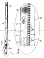
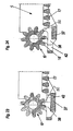
- the Fig. 1 shows diagrammatically and schematically a furniture body with a hinged drawer in the front end position
- the Fig. 2 also schematically shows a furniture body and a drawer in the front end position
- the parts of the stabilization device are shown diagrammatically
- the Fig. 3 shows diagrammatically and exploded the parts of the stabilizer and one side of the drawer
- the Fig. 4 shows diagrammatically and exploded the rear end of a rack and the drawer-side parts of the device on one side of the drawer
- the Fig. 5 shows a vertical section through the device on one side of the drawer, wherein the gear is shown in normal operation
- the Fig. 6 shows a vertical section through one side of a device, wherein the gear is shown during the hanging of the drawer
- the Fig. 1 shows diagrammatically and schematically a furniture body with a hinged drawer in the front end position
- the Fig. 2 also schematically shows a furniture body and a drawer in the front end position
- the parts of the stabilization device are shown
- FIGS. 7 to 9 show diagrammatically one side of the device, showing various stages of engagement of the gear with the rack
- the Fig. 10 shows a section through a furniture body and a schematic plan view of a drawer during insertion of the drawer
- the Fig. 11 shows a section through a furniture body and a schematic plan view of a correctly inserted drawer
- the Fig. 12 shows a section through a furniture body and a schematic plan view of an obliquely inserted drawer
- the Fig. 13 shows a side view of a rack
- the Fig. 13a shows the section A of Fig. 13
- the Fig. 14 shows another side view of a rack
- the Fig. 14a shows the section A of Fig. 14 .
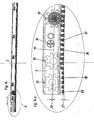
- FIGS. 15 and 16 show diagrammatically the rear end of a rack and the drawer-side parts of the stabilizing device according to the invention on one side of the drawer
- the FIGS. 17 and 18 show two views of the device according to the invention on one side of the drawer partially in section, wherein the gear is shown in normal operation
- the Fig. 19 shows a diagram of the rear end of the rack
- the Fig. 20 shows a side view of the rear end of the rack
- the Fig. 21 shows a side view of the rear end of the rack and the locked direction of rotation of the gear
- the Fig. 22 shows a side view of the rear end of the rack and the movable tooth in the tilted position
- the FIGS. 23 and 24 each show a side view of the rear end of a rack and a movable tooth according to a further embodiment of the invention
- the Fig. 25 schematically shows another embodiment of a movable tooth.
- a drawer 3 is movable by means of a conventional Auszieh Operationssgarnitur 4 between the side walls 1 of a furniture body.
- Auszieh In the Auszieh solutionsgarnitur 4 may be both a single extension with a body-side mounting rail and a loading-side drawer on both sides of the drawer or a full extension, in which a middle rail is mounted between the body-side mounting rail and the loading side pull-out.
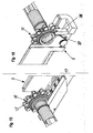
- the gears 10 store by means of their stub axles 27 in bearing bodies 7, which in turn are mounted vertically displaceable in brackets 6.
- the bearing body 7 are guided in the holding bodies 6, for example by means of a dovetail guide 26.
- the brackets 6 are attached to the drawer 3, preferably to the drawer 2.
- the drawer 2 are provided with a rear angled web 28 on which the brackets 6 are pushed.
- the stub axles 27 of the gears 10 protrude through the bearing body 7 and into a sleeve-shaped rod 11, which is provided at least in its two end regions with an internal toothing.
- the two gears 10 are rotatably connected to each other on the two sides of the drawer 3.
- a slider 9 is mounted below the gear 10, which is displaceable perpendicular to the direction of travel of the drawer 3.
- the slider 9 is acted upon by a spring 8 and pressed to the rack 5.
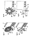
- Each rack 5 is provided at its free edge with a horizontal guide bar 14 which ends at the rear end of the rack 5 at a distance in front of a guide block 29.
- the guide block 29 is bounded at its front end by a slanted guide 15.
- Above the guide rail 14 is a vertical guide wall 30th
- the teeth 17, 18 are each arranged in a groove 31 of the rack 5 and are bounded by lateral guide walls.
- Each rack 5 is provided at its rear end with a correction region 24 in which the height of the teeth 18 is approximately half the height of the teeth 17 in the remaining running region 25 of the rack.
- the height of the teeth 18 is at most 3/4 of the height of the teeth 17 and is preferably in a range between 2/3 and half the height of the teeth 17th
- the racks 5, which are made of a plastic material, are screwed by means of screws 16 to the body side wall 1, wherein the rearmost screw 16, d. H. the rearmost attachment point of the rack 5 on the side wall 1 of the furniture body is located at a distance a in front of the rear end of the rack 5.
- the distance between the rear end of the rack 5 and the rearmost attachment point is greater than the length of the correction region 24. Due to the elasticity of the rack 5, the rear end of the rack 5 can bend under pressure elastically downwards, which in the Fig. 14a designated by the reference numeral 21.
- the drawer 3 is inserted so far into the furniture body until the slide 9 abut the inclined guides 15 of the racks 5. Due to the inclined guides 15, the slide 9 are pressed down and engage below the edge 32 of the blocks 29, where they are pushed by the springs 8 under the racks 5.
- the slider 9 does not slip through the limited by the inclined guide 15 and the end of the guide rail 14 opening upwards, but he snaps below the guide rail 14 and is guided below this.
- This normal operating position is in the Fig. 5 and 9 shown. In this position, the slider 9, a lifting of the gears 10 is prevented by the teeth 17 of the racks 5.
- the gear 10 rotates on the upper end surfaces of the teeth 18, wherein the rear end of the rack 5 is pressed by the dimension 21 down and the axis of the gear 10 is pressed by the dimension 20 upwards.
- the gear 10 can thus be rotated over the teeth 18 until it is again brought into engagement with the teeth 18 in the rear end position (see Fig. 13a ).
- the tooth head width 33 of the teeth 18 is greater than the tooth head width 34 of the teeth 17th
- the reference numeral 19 the engagement axis between the gear 10 and the rack 5 is marked.
- a movable tooth 50 In the embodiments of the FIGS. 15 to 25 is located in the correction area a movable tooth 50.
- This movable tooth 50 is either, as in the Fig. 17 to 22nd shown tiltable or rotatably mounted on an axis 23 or, as in the embodiment of the Fig. 23 to 24 shown, linearly displaceable.
- the Fig. 25 shows a variant of the tiltable mounting, wherein the tooth 50 can escape the gear 10 side.
- the distance between the tooth 50 and the next rigid tooth 17 of the rack 5 is about twice as large as the distance between two adjacent rigid teeth 17th
- the movable tooth 50 can only escape in one direction, ie in the embodiment of the Fig. 17 to 24
- the tooth 50 can be moved only in the direction of the rearmost fixed tooth 17 of the rack 5.
- the lever 35 at the free end of which the tooth 50 is formed, can swing out only in the direction of the arrow.
- the left side gear 10 may rotate until the gear 10 on the right side of the drawer 3 has reached the rearmost position. Now the drawer 3 is straight and can be pulled straight out of the furniture carcass.
- the tiltably mounted on the axis 23 tooth 50 is provided with a laterally vertically projecting arm 36, on which a spring 37 presses.
- the spring 37 pushes the tooth 50 in the vertical position.
- a stopper is provided so that the tooth 50 can only be tilted in the direction of the fixed teeth 17. Thereby, a rotation of the gear 10 in the direction of arrow A of Fig. 22 possible. A rotation of the gear 10 in the direction of arrow B of Fig. 21 is prevented by this stop at a fixed drawer 3. The gear 10 can only then in the direction of the arrow B are rotated when the drawer 3 moves out of the furniture body.
- the movable tooth 50 is formed on a displaceable block 38, which is movable in a recess 42 of the rack 5.
- the pad 38 is linearly displaceable in the direction of the rack 5 and is urged rearward by a spring 37 which is a helical compression spring this time.
- the rear gear 10 can be in place in the direction of arrow A of Fig. 24 rotate.
- the block 38 is moved with the tooth 50 against the pressure of the spring 37 to the front.
- the tooth 50 is formed on an arm 35 which is rotatable about an axis 39.
- the tooth 50 is provided with a vertical inclined surface 40.
Landscapes
- Drawers Of Furniture (AREA)
Description
Die Erfindung bezieht sich auf eine Schublade, welche gegenüber einem Möbelkorpus verfahrbar ist, mit einer Vorrichtung zur Stabilisierung des Laufverhaltens der Schublade gegenüber dem Möbelkorpus, wobei an beiden Seiten der Schublade ein Zahnrad gelagert ist und die beiden Zahnräder, die drehfest miteinander verbunden sind, mit korpusseitigen Zahnstangen kämmen.The invention relates to a drawer, which is movable relative to a furniture body, with a device for stabilizing the running behavior of the drawer relative to the furniture body, wherein on both sides of the drawer a gear is mounted and the two gears, which are rotatably connected to each other, with combing body-side racks.
Insbesondere bei sehr schmalen oder sehr breiten Schubladen ist es vorteilhaft, eine Seitenstabilisierung für eine Schublade vorzusehen, die ein seitliches Verkanten der Schublade verhindert. Aus der
Aufgabe der Erfindung ist es, die Schublade der eingangs erwähnten Art dahingehend zu verbessern, dass das Einhängen derselben erleichtert wird. Dabei soll es möglich sein, die seitliche Ausrichtung einer etwas schräg in den Möbelkorpus eingeführten Schublade zu korrigieren.The object of the invention is to improve the drawer of the type mentioned in that the suspension is facilitated. It should be possible to correct the lateral orientation of a slightly obliquely introduced into the furniture body drawer.
Die erfindungsgemäße Aufgabe wird dadurch gelöst, dass an jeder Zahnstange mindestens ein an das hintere Ende der Zahnreihe anschließender durch das Zahnrad relativ zur Zahnstange bewegbarer Zahn vorgesehen ist. Der bewegbare Zahn erlaubt ein "Überspringen" von Zähnen am Zahnrad und der Zahnstange und damit eine Korrektur der Lage einer allenfalls schräg eingeführten Schublade.The object of the invention is achieved in that at least one subsequent to the rear end of the row of teeth is provided by the gear relative to the rack movable tooth on each rack. The movable tooth allows a "skipping" of teeth on the gear and the rack and thus a correction of the position of a possibly obliquely introduced drawer.
Nachfolgend werden Ausführungsbeispiele der Erfindung anhand der Figuren der beiliegenden Zeichnungen beschrieben. Die
Die
die
die
die
die
die
die
die
die
die
die
die
die
die
die
die
die
die
die
die
die
the
the
the
the
the
the
the
the
the
the
the
the
the
the
the
the
the
the
the
the
Eine Schublade 3 ist mittels einer herkömmlichen Ausziehführungsgarnitur 4 zwischen den Seitenwänden 1 eines Möbelkorpus verfahrbar.A
Bei der Ausziehführungsgarnitur 4 kann es sich sowohl um einen Einfachauszug mit einer korpusseitigen Tragschiene und einer ladenseitigen Schublade an beiden Seiten der Schublade oder um einen Vollauszug handeln, bei dem zwischen der korpusseitigen Tragschiene und der ladenseitigen Ausziehschiene eine Mittelschiene gelagert ist.In the
Unterhalb der korpusseitigen Tragschiene sind an den Seitenwänden 1 Zahnstangen 5 befestigt, die mit Zähnen 17, 18 versehen sind.Below the body-
Mit den Zähnen 17, 18 der Zahnstangen 5 kämmen Zahnräder 10, die an beiden Seiten der Schublade 3 gelagert sind.With the
Die Zahnräder 10 lagern mittels ihrer Steckachsen 27 in Lagerkörpern 7, die wiederum in Halterungen 6 höhenverschiebbar gelagert sind. Die Lagerkörper 7 sind dabei in den Haltekörpern 6 beispielsweise mittels einer Schwalbenschwanzführung 26 geführt.The
Die Halterungen 6 sind an der Schublade 3, vorzugsweise an den Schubladenzargen 2 befestigt. Im Ausführungsbeispiel sind die Schubladenzargen 2 mit einem hinteren abgewinkelten Steg 28 versehen, auf den die Halterungen 6 aufgeschoben sind.The
Die Steckachsen 27 der Zahnräder 10 ragen durch die Lagerkörper 7 hindurch und in eine hülsenförmige Stange 11, die zumindestens in ihren beiden Endbereichen mit einer Innenverzahnung versehen ist. Dadurch sind die beiden Zahnräder 10 an den beiden Seiten der Schublade 3 drehfest miteinander verbunden.The
In jedem Lagerkörper 7 ist unterhalb des Zahnrades 10 ein Schieber 9 gelagert, der senkrecht zur Verfahrrichtung der Schublade 3 verschiebbar ist. Der Schieber 9 wird von einer Feder 8 beaufschlagt und zur Zahnstange 5 gedrückt.In each bearing
Jede Zahnstange 5 ist an ihrem freien Rand mit einer horizontalen Führungsleiste 14 versehen, die beim hinteren Ende der Zahnstange 5 mit Abstand vor einem Führungsklotz 29 endet. Der Führungsklotz 29 wird an seinem vorderen Ende von einer Schrägführung 15 begrenzt. Oberhalb der Führungsleiste 14 befindet sich eine vertikale Führungswand 30.Each
Die Zähne 17, 18 sind jeweils in einer Nut 31 der Zahnstange 5 angeordnet und werden von seitlichen Führungswänden begrenzt.The
Jede Zahnstange 5 ist an ihrem hinteren Ende mit einem Korrekturbereich 24 versehen, in dem die Höhe der Zähne 18 in etwa halb so groß ist als die Höhe der Zähne 17 im restlichen Laufbereich 25 der Zahnstange.Each
Die Höhe der Zähne 18 beträgt maximal 3/4 der Höhe der Zähne 17 und liegt vorzugsweise in einem Bereich zwischen 2/3 und der Hälfte der Höhe der Zähne 17.The height of the
Die Zahnstangen 5, die aus einem Kunststoffmaterial gefertigt sind, sind mittels Schrauben 16 an der Korpusseitenwand 1 angeschraubt, wobei die hinterste Schraube 16, d. h. der hinterste Befestigungspunkt der Zahnstange 5 an der Seitenwand 1 des Möbelkorpus sich im Abstand a vor dem hinteren Ende der Zahnstange 5 befindet.The
Wie insbesondere aus den
Beim Einschieben der Schublade 3 in den Möbelkorpus befinden sich die Zahnräder 10, wie in der
Die Schublade 3 wird so weit in den Möbelkorpus eingeschoben, bis die Schieber 9 an den Schrägführungen 15 der Zahnstangen 5 anstoßen. Bedingt durch die Schrägführungen 15 werden die Schieber 9 nach unten gedrückt und rasten unterhalb der Kante 32 der Klötze 29 ein, wobei sie von den Federn 8 unter die Zahnstangen 5 geschoben werden.The
Wird die Schublade 3 anschließend wieder geöffnet, d.h. aus dem Möbelkorpus herausgezogen, rutscht der Schieber 9 nicht durch die von der Schrägführung 15 und dem Ende der Führungsleiste 14 begrenzte Öffnung nach oben, sondern er rastet unterhalb der Führungsleiste 14 ein und wird unterhalb dieser geführt. Diese normale Betriebsstellung ist in den
Wurde die Schublade 3 gerade in den Möbelkorpus eingeschoben, so sind die Zähne der Zahnräder 10 korrekt wie bei einem üblichen Zahnstangengetriebe mit den Zähnen 17, 18 der Zahnstange im Eingriff. Diese Situation ist in den
Kommt es jedoch zu einem Einspurfehler und somit zu einer Schrägstellung der Schublade 3, wie in der
Aufgrund des Korrekturbereiches 24 ist es möglich, die Stellung der Schublade 3 zu korrigieren. Diese Situation ist in der
Wird in diesem Fall die rechte Seite der Schublade 3 weiter in den Möbelkorpus hineingedrückt, dreht sich das Zahnrad 10 auf den oberen Abschlußflächen der Zähne 18, wobei das hintere Ende der Zahnstange 5 um das Maß 21 nach unten gedrückt und die Achse des Zahnrades 10 um das Maß 20 nach oben gedrückt wird. Das Zahnrad 10 kann somit über die Zähne 18 hinweggedreht werden, bis es in der hinteren Endstellung wiederum in Eingriff mit den Zähnen 18 gebracht wird (siehe
Wird die Schublade wieder geöffnet, rollt das Zahnrad 10 normal mit den Zähnen 18, 17 kämmend am Zahnprofil der Zahnstange 5 ab.When the drawer is opened again, the
Mit dem Bezugszeichen 19 ist die Eingriffsachse zwischen dem Zahnrad 10 und der Zahnstange 5 gekennzeichnet.The
In den Ausführungsbeispielen nach den
Die
Gemeinsam ist allen Ausführungsbeispielen, dass der bewegbare Zahn 50 nur in einer Richtung ausweichen kann, d.h. im Ausführungsbeispiel nach den
Beim Einschieben der Schublade 3 in den Möbelkorpus kämmen die Zahnräder 10 mit den Zähnen 17 der Zahnstangen 5. In der hintersten Stellung der Schublade umfassen je zwei Zähne 10' eines Zahnrades 10 den bewegbaren Zahn 50 der jeweiligen Zahnstange 5.When inserting the
Wurde die Schublade 3 gerade in den Möbelkorpus eingeschoben, so sind die Zähne 10' der Zahnräder 10 korrekt wie bei einem üblichen Zahnstangengetriebe mit den Zähnen 17 der Zahnstange 5 im Eingriff.If the
Kommt es jedoch zu einem Einspurfehler und somit zu einer Schrägstellung der Schublade 3, wie in der
Aufgrund des bewegbaren Zahnes 50 auf der linken Seite ist es nun möglich, die Stellung der Schublade 3 zu korrigieren. Diese Situation ist in den
Wird in diesem Fall die rechte Seite der Schublade 3 weiter in den Möbelkorpus hineingedrückt, dreht sich das Zahnrad 10 auf der linken Seite auf der Stelle. Dabei wird im Ausführungsbeispiel nach den
Das Zahnrad 10 auf der linken Seite kann sich so lange drehen, bis das Zahnrad 10 auf der rechten Seite der Schublade 3 die hinterste Stellung erreicht hat. Nun ist die Schublade 3 gerade ausgerichtet und kann gerade geführt aus dem Möbelkorpus herausgezogen werden.The
Der auf der Achse 23 kippbar gelagerte Zahn 50 ist mit einem seitlich vertikal abstehenden Arm 36 versehen, auf den eine Feder 37 drückt. Die Feder 37 drückt den Zahn 50 in die vertikale Stellung.The tiltably mounted on the
Es ist ein Anschlag vorgesehen, sodass der Zahn 50 nur in der Richtung zu den feststehenden Zähnen 17 gekippt werden kann. Dadurch ist eine Drehung des Zahnrades 10 in der Richtung des Pfeiles A der
Im Ausführungsbeispiel nach den
Wurde die Schublade 3 schräg in den Möbelkorpus eingefahren, so kann sich das hintere Zahnrad 10 auf der Stelle in der Richtung des Pfeiles A der
In der Gegenrichtung ist das Zahnrad 10 gesperrt, d.h. der Klotz 38 mit dem Zahn 50 kann nicht weiter nach links verfahren werden, als es in der
Im Ausführungsbeispiel nach der
Der Zahn 50 ist mit einer vertikalen Schrägfläche 40 versehen.The
Drückt der Zahn 10' des Zahnrades 10, das sich in seiner hintersten Position befindet, bei der Drehung des Zahnrades 10 auf die Schrägfläche 40, so kann der bewegbare Zahn 50 der Zahnstange 5 gegen den Druck der Feder 37 in der Richtung des Pfeiles A der
Es ist ein Anschlag 41 vorgesehen, der ein Ausweichen des Zahnes 50 in der Gegenrichtung unmöglich macht und daher das Zahnrad 10 in dieser Drehrichtung sperrt.There is a
Claims (14)
- A drawer (3) which is mounted displaceably relative to a furniture carcass, with a device for stabilisation of the running behaviour of the drawer (3) relative to the furniture carcass, wherein a gear (10) is mounted at both sides of the drawer (3) and the two gears (10) which are non-rotatably connected together mesh with carcass-side racks (5), characterised in that provided at each rack (5) is at least one tooth (50) which adjoins the rear end of the row of teeth and which is movable by the gear (10) relative to the rack (5).
- The drawer according to claim 1, characterised in that the spacing of the movable tooth (50) from the rearmost fixed tooth (17) of the rack (5) is approximately twice as great as the spacing between two adjacent fixed teeth (17) of the rack (5).
- The drawer according to claim 1 or 2, characterised in that the movable tooth (50) is tiltable about a horizontal axis (23).
- The drawer according to claim 3, characterised in that the movable tooth (50) is mounted on a shaft (23) anchored in the rack (5).
- The drawer according to claim 4, characterised in that the tooth (50) is held clampingly on the shaft (23).
- The according to one of the claims 1 to 5, characterised in that the movable tooth (50) is acted upon by a spring (37) which urges it into the upright position.
- The drawer according to claim 6, characterised in that the movable tooth (50) is connected to an arm (36) which is engaged by the spring (37).
- The drawer according to one of the claims 3 to 7, characterised in that the movable tooth (50) is tiltable only in one direction.
- The drawer according to claim 8, characterised in that the movable tooth (50) is tiltable in the direction towards the fixed teeth (17) of the rack (5).
- The drawer according to claim 1 or 2, characterised in that the movable tooth (50) is linearly displaceable in the longitudinal direction of the rack (5).
- The drawer according to claim 10, characterised in that the displaceable tooth (50) is urged by a spring (37) towards the furniture rear wall.
- The drawer according to claim 10 or 11, characterised in that the linearly displaceable tooth (50) is arranged on a lug (38) fitted into an opening (42) at the rear end of the rack (5).
- The drawer according to one of the claims 10 to 12, characterised in that the linearly displaceable tooth (50) is movable by the gear (10) only in the direction towards the front of the article of furniture,
- The drawer according to claim 1 or 2, characterised in that the movable tooth (50) has a vertical inclined surface (40), by way of which the tooth (50) can be pressed by the gear (10) to the side out of the line of the gear (10).
Applications Claiming Priority (5)
| Application Number | Priority Date | Filing Date | Title |
|---|---|---|---|
| AT47399 | 1999-03-17 | ||
| AT0047399A AT410162B (en) | 1999-03-17 | 1999-03-17 | Drawer motion stabilising device comprises correcting area with small on one or both racks which cooperate with pinions on drawer sides |
| AT152399 | 1999-09-06 | ||
| AT0152399A AT410163B (en) | 1999-09-06 | 1999-09-06 | Drawer motion stabilising device comprises correcting area with small on one or both racks which cooperate with pinions on drawer sides |
| EP00104058A EP1036526B1 (en) | 1999-03-17 | 2000-02-28 | Device for stabilising the running behaviour of a drawer moving in a furniture casing |
Related Parent Applications (2)
| Application Number | Title | Priority Date | Filing Date |
|---|---|---|---|
| EP00104058.3 Division | 2000-02-28 | ||
| EP00104058A Division EP1036526B1 (en) | 1999-03-17 | 2000-02-28 | Device for stabilising the running behaviour of a drawer moving in a furniture casing |
Publications (3)
| Publication Number | Publication Date |
|---|---|
| EP1574151A2 EP1574151A2 (en) | 2005-09-14 |
| EP1574151A3 EP1574151A3 (en) | 2006-08-16 |
| EP1574151B1 true EP1574151B1 (en) | 2013-11-06 |
Family
ID=25592852
Family Applications (2)
| Application Number | Title | Priority Date | Filing Date |
|---|---|---|---|
| EP05012879.2A Expired - Lifetime EP1574151B1 (en) | 1999-03-17 | 2000-02-28 | Device for stabilising the running behaviour of a drawer moving in a furniture casing |
| EP00104058A Expired - Lifetime EP1036526B1 (en) | 1999-03-17 | 2000-02-28 | Device for stabilising the running behaviour of a drawer moving in a furniture casing |
Family Applications After (1)
| Application Number | Title | Priority Date | Filing Date |
|---|---|---|---|
| EP00104058A Expired - Lifetime EP1036526B1 (en) | 1999-03-17 | 2000-02-28 | Device for stabilising the running behaviour of a drawer moving in a furniture casing |
Country Status (4)
| Country | Link |
|---|---|
| EP (2) | EP1574151B1 (en) |
| AT (2) | ATE302558T1 (en) |
| DE (1) | DE50011002D1 (en) |
| ES (2) | ES2244369T3 (en) |
Cited By (1)
| Publication number | Priority date | Publication date | Assignee | Title |
|---|---|---|---|---|
| CN108741784A (en) * | 2018-06-04 | 2018-11-06 | 安徽知之信息科技有限公司 | A kind of robot for sundries storage |
Families Citing this family (27)
| Publication number | Priority date | Publication date | Assignee | Title |
|---|---|---|---|---|
| DE10228470A1 (en) | 2002-06-26 | 2004-01-15 | Grass Gmbh | drawer guide |
| DE202004016393U1 (en) * | 2004-10-21 | 2005-12-29 | Grass Gmbh | Device for stabilizing the running behavior of a movable furniture body in a furniture part |
| AT8111U1 (en) * | 2004-10-22 | 2006-02-15 | Fulterer Gmbh | pull-out |
| DE202006000711U1 (en) * | 2006-01-18 | 2006-04-06 | Anton Schneider Gmbh & Co Kg | Differential extract for drawers or the like. |
| ES2318984B1 (en) * | 2006-08-04 | 2009-11-17 | Miguel Angel Rioja Calvo | DEVICE FOR FURNITURE DRAWERS. |
| KR100790543B1 (en) * | 2006-10-25 | 2008-01-02 | 엘지전자 주식회사 | Basket Assembly Rail Assembly |
| US7594707B2 (en) | 2007-08-15 | 2009-09-29 | Whirlpool Corporation | Snap-in bearing rack and pinion system |
| DE202008012077U1 (en) * | 2008-09-11 | 2010-02-25 | Paul Hettich Gmbh & Co. Kg | Synchronous guide of a push element |
| TW201039777A (en) | 2009-05-05 | 2010-11-16 | Zong-Yao Chen | Drawing stabilization structure of cupboard-drawing bearing member |
| DE202009016105U1 (en) * | 2009-07-06 | 2010-12-02 | Paul Hettich Gmbh & Co. Kg | Synchronous guide a push element and furniture |
| CN102090800B (en) * | 2009-12-15 | 2015-04-08 | 陈崇尧 | Pulling and Stable Structure of Cabinet Pulling Bearing Parts |
| CN101716032B (en) * | 2009-12-17 | 2012-01-18 | 伍志勇 | Balancing mechanism of drawer |
| AT509256B1 (en) * | 2009-12-23 | 2013-06-15 | Blum Gmbh Julius | RAIL SYSTEM FOR DRAWERS |
| AT509257B1 (en) | 2009-12-23 | 2013-09-15 | Blum Gmbh Julius | RAIL SYSTEM FOR DRAWERS |
| TW201225884A (en) * | 2010-12-30 | 2012-07-01 | Chong-Yao Chen | Drawing synchronization device of side-travelling type slide rail and support unit and slide rail unit thereof |
| AT13201U1 (en) * | 2011-01-28 | 2013-08-15 | Blum Gmbh Julius | Furniture part with a torque transmitting shaft |
| AT511511B1 (en) | 2011-05-20 | 2015-05-15 | Blum Gmbh Julius | SYNCHRONIZATION DEVICE FOR A MOVABLE STORED FURNITURE |
| TW201320927A (en) | 2011-11-21 | 2013-06-01 | 陳崇堯 | Pulling synchronization device and its shaft assembly unit |
| AT512382B1 (en) * | 2011-12-27 | 2016-05-15 | Blum Gmbh Julius | SYNCHRONIZATION DEVICE FOR A DRAWER |
| DE202012002127U1 (en) * | 2012-02-29 | 2013-06-06 | Grass Gmbh | Device for stabilizing the running behavior of a movable in a furniture body furniture part |
| KR20130115546A (en) * | 2012-04-12 | 2013-10-22 | 삼성전자주식회사 | Sliding apparatus and refrigerator having the same |
| US20130270987A1 (en) * | 2012-04-17 | 2013-10-17 | Electrolux Home Products, Inc. | Freezer slide rack alignment |
| DE102012111977B4 (en) | 2012-12-07 | 2024-01-11 | Paul Hettich Gmbh & Co. Kg | Thrust element |
| CN103960890B (en) * | 2014-05-14 | 2016-08-31 | 伍志勇 | A kind of auxiliary stabilizing mechanism of drawer sliding rail synchronizer |
| TWI612231B (en) | 2017-03-20 | 2018-01-21 | 川湖科技股份有限公司 | Gear arrangement |
| CN108652284B (en) * | 2017-03-28 | 2023-08-08 | 川湖科技股份有限公司 | gear unit |
| AT520817B1 (en) | 2018-02-01 | 2019-08-15 | Blum Gmbh Julius | Arrangement of pull-out guide, rail synchronization device and driver |
Family Cites Families (14)
| Publication number | Priority date | Publication date | Assignee | Title |
|---|---|---|---|---|
| GB436082A (en) * | 1934-03-28 | 1935-09-30 | William Mackey Stavers | Improvements in rack and pinion mechanism |
| US2214291A (en) | 1937-10-13 | 1940-09-10 | Wyckoff William Le Roy | Cabinet |
| US2410643A (en) * | 1944-10-17 | 1946-11-05 | Fielding Charles Stuart | Rack and pinion mechanism |
| US2620253A (en) * | 1948-05-20 | 1952-12-02 | Robert C Read | Glide control means for drawers |
| US3323853A (en) * | 1965-12-06 | 1967-06-06 | Art Metal Inc | Filing cabinet drawer motion control means |
| DE2609977A1 (en) * | 1976-03-10 | 1977-09-15 | Siemens Ag | INLET ROD FOR DRIVEN CONVEYOR CARRIAGE |
| US4226490A (en) | 1978-08-04 | 1980-10-07 | General Electric Company | Stabilizing arrangement for movably mounted drawer or rack |
| DD217293A1 (en) * | 1983-07-18 | 1985-01-09 | Groeditz Stahl Walzwerk Veb | RACK POWER |
| DE8905197U1 (en) * | 1989-04-25 | 1989-06-08 | Paul Hettich GmbH & Co, 4983 Kirchlengern | Device for ensuring the parallel running of a furniture extension |
| NL9100758A (en) * | 1991-05-02 | 1992-12-01 | Regout Nv Thomas | ANTI-SHAKING SYSTEM FOR A DRAWER. |
| US5409309A (en) | 1993-04-19 | 1995-04-25 | Whirlpool Corporation | Dishrack motion control arrangement for a dishwasher |
| GB9416305D0 (en) * | 1994-08-12 | 1994-10-05 | Alliedsignal Ltd | Driving arrangement |
| TR199501601A2 (en) * | 1994-12-19 | 1996-07-21 | Bosch Siemens Hausgeraete | Cooler. |
| DE19718069C1 (en) * | 1997-04-29 | 1998-05-28 | Schock Metallwerk | Parallel extension guide for insert from body |
-
2000
- 2000-02-28 AT AT00104058T patent/ATE302558T1/en active
- 2000-02-28 ES ES00104058T patent/ES2244369T3/en not_active Expired - Lifetime
- 2000-02-28 DE DE50011002T patent/DE50011002D1/en not_active Expired - Lifetime
- 2000-02-28 EP EP05012879.2A patent/EP1574151B1/en not_active Expired - Lifetime
- 2000-02-28 ES ES05012879.2T patent/ES2445162T3/en not_active Expired - Lifetime
- 2000-02-28 EP EP00104058A patent/EP1036526B1/en not_active Expired - Lifetime
-
2003
- 2003-11-03 AT AT0075703U patent/AT6674U3/en not_active IP Right Cessation
Cited By (1)
| Publication number | Priority date | Publication date | Assignee | Title |
|---|---|---|---|---|
| CN108741784A (en) * | 2018-06-04 | 2018-11-06 | 安徽知之信息科技有限公司 | A kind of robot for sundries storage |
Also Published As
| Publication number | Publication date |
|---|---|
| EP1036526A1 (en) | 2000-09-20 |
| EP1574151A2 (en) | 2005-09-14 |
| EP1574151A3 (en) | 2006-08-16 |
| ES2445162T3 (en) | 2014-02-28 |
| EP1036526B1 (en) | 2005-08-24 |
| AT6674U3 (en) | 2004-12-27 |
| ATE302558T1 (en) | 2005-09-15 |
| ES2244369T3 (en) | 2005-12-16 |
| DE50011002D1 (en) | 2005-09-29 |
| AT6674U2 (en) | 2004-02-25 |
Similar Documents
| Publication | Publication Date | Title |
|---|---|---|
| EP1574151B1 (en) | Device for stabilising the running behaviour of a drawer moving in a furniture casing | |
| EP0700649B1 (en) | Closing device for drawers | |
| AT395095B (en) | LOCKING DEVICE FOR DRAWERS | |
| EP3603449B1 (en) | Pull-out guide for a drawer | |
| EP1978842B1 (en) | Drive mechanism for a furniture part mounted in a movable manner on a piece of furniture | |
| AT512934B1 (en) | drawer | |
| EP1440632A1 (en) | Chair with quick-adjustable force accumulator | |
| EP2012619A2 (en) | Flush-mounted guiding arrangement for furniture parts, especially drawers in the carcass of pieces of furniture | |
| WO2019033136A1 (en) | drawer | |
| DE69203929T2 (en) | System to prevent drawers from jamming. | |
| WO2005044046A1 (en) | Automatic retraction mechanism for drawer pull-out guides | |
| AT413473B (en) | SELF FEED DEVICE | |
| DE69503828T2 (en) | Blocking device for an extension With regard to a piece of furniture, and piece of furniture equipped with it | |
| DE3501442C2 (en) | ||
| AT410162B (en) | Drawer motion stabilising device comprises correcting area with small on one or both racks which cooperate with pinions on drawer sides | |
| EP3745916B1 (en) | Arrangement of sliding rails, railsynchronisationdevice and actuacting pin | |
| EP0875178B1 (en) | Parallel drawer slide | |
| AT410163B (en) | Drawer motion stabilising device comprises correcting area with small on one or both racks which cooperate with pinions on drawer sides | |
| DE2216934C3 (en) | Support plate for adjusting the inclination of two parts of a piece of furniture for sitting or leaning | |
| DE29520845U1 (en) | Device for the longitudinal adjustment of a ski binding part | |
| DE9005705U1 (en) | Drawer | |
| EP1159896B1 (en) | Pivotal fitting for furniture for sitting or lying on | |
| DE9418689U1 (en) | Drawer slide | |
| EP0016878B1 (en) | Device for adjusting a tiltable part of a bedframe | |
| CH643127A5 (en) | Device for adjusting a pivotable bed frame part |
Legal Events
| Date | Code | Title | Description |
|---|---|---|---|
| PUAI | Public reference made under article 153(3) epc to a published international application that has entered the european phase |
Free format text: ORIGINAL CODE: 0009012 |
|
| AC | Divisional application: reference to earlier application |
Ref document number: 1036526 Country of ref document: EP Kind code of ref document: P |
|
| AK | Designated contracting states |
Kind code of ref document: A2 Designated state(s): AT DE ES IT |
|
| PUAL | Search report despatched |
Free format text: ORIGINAL CODE: 0009013 |
|
| AK | Designated contracting states |
Kind code of ref document: A3 Designated state(s): AT DE ES IT |
|
| 17P | Request for examination filed |
Effective date: 20060920 |
|
| AKX | Designation fees paid |
Designated state(s): AT DE ES IT |
|
| 17Q | First examination report despatched |
Effective date: 20120515 |
|
| GRAP | Despatch of communication of intention to grant a patent |
Free format text: ORIGINAL CODE: EPIDOSNIGR1 |
|
| INTG | Intention to grant announced |
Effective date: 20130805 |
|
| GRAS | Grant fee paid |
Free format text: ORIGINAL CODE: EPIDOSNIGR3 |
|
| GRAA | (expected) grant |
Free format text: ORIGINAL CODE: 0009210 |
|
| AC | Divisional application: reference to earlier application |
Ref document number: 1036526 Country of ref document: EP Kind code of ref document: P |
|
| AK | Designated contracting states |
Kind code of ref document: B1 Designated state(s): AT DE ES IT |
|
| REG | Reference to a national code |
Ref country code: AT Ref legal event code: REF Ref document number: 638830 Country of ref document: AT Kind code of ref document: T Effective date: 20131215 |
|
| REG | Reference to a national code |
Ref country code: DE Ref legal event code: R096 Ref document number: 50016337 Country of ref document: DE Effective date: 20140102 |
|
| REG | Reference to a national code |
Ref country code: ES Ref legal event code: FG2A Ref document number: 2445162 Country of ref document: ES Kind code of ref document: T3 Effective date: 20140228 |
|
| REG | Reference to a national code |
Ref country code: DE Ref legal event code: R097 Ref document number: 50016337 Country of ref document: DE |
|
| PLBE | No opposition filed within time limit |
Free format text: ORIGINAL CODE: 0009261 |
|
| STAA | Information on the status of an ep patent application or granted ep patent |
Free format text: STATUS: NO OPPOSITION FILED WITHIN TIME LIMIT |
|
| 26N | No opposition filed |
Effective date: 20140807 |
|
| REG | Reference to a national code |
Ref country code: DE Ref legal event code: R097 Ref document number: 50016337 Country of ref document: DE Effective date: 20140807 |
|
| REG | Reference to a national code |
Ref country code: DE Ref legal event code: R079 Ref document number: 50016337 Country of ref document: DE Free format text: PREVIOUS MAIN CLASS: A47B0088040000 Ipc: A47B0088400000 |
|
| PGFP | Annual fee paid to national office [announced via postgrant information from national office to epo] |
Ref country code: IT Payment date: 20170221 Year of fee payment: 18 |
|
| PGFP | Annual fee paid to national office [announced via postgrant information from national office to epo] |
Ref country code: DE Payment date: 20170428 Year of fee payment: 18 |
|
| PGFP | Annual fee paid to national office [announced via postgrant information from national office to epo] |
Ref country code: ES Payment date: 20170331 Year of fee payment: 18 |
|
| PGFP | Annual fee paid to national office [announced via postgrant information from national office to epo] |
Ref country code: AT Payment date: 20180228 Year of fee payment: 19 |
|
| REG | Reference to a national code |
Ref country code: DE Ref legal event code: R119 Ref document number: 50016337 Country of ref document: DE |
|
| PG25 | Lapsed in a contracting state [announced via postgrant information from national office to epo] |
Ref country code: DE Free format text: LAPSE BECAUSE OF NON-PAYMENT OF DUE FEES Effective date: 20180901 |
|
| PG25 | Lapsed in a contracting state [announced via postgrant information from national office to epo] |
Ref country code: IT Free format text: LAPSE BECAUSE OF NON-PAYMENT OF DUE FEES Effective date: 20180228 |
|
| REG | Reference to a national code |
Ref country code: ES Ref legal event code: FD2A Effective date: 20190801 |
|
| REG | Reference to a national code |
Ref country code: AT Ref legal event code: MM01 Ref document number: 638830 Country of ref document: AT Kind code of ref document: T Effective date: 20190228 |
|
| PG25 | Lapsed in a contracting state [announced via postgrant information from national office to epo] |
Ref country code: ES Free format text: LAPSE BECAUSE OF NON-PAYMENT OF DUE FEES Effective date: 20180228 |
|
| PG25 | Lapsed in a contracting state [announced via postgrant information from national office to epo] |
Ref country code: AT Free format text: LAPSE BECAUSE OF NON-PAYMENT OF DUE FEES Effective date: 20190228 |